
MLSE 129 - Washing machine SCHOLTES - Free user manual and instructions
Find the device manual for free MLSE 129 SCHOLTES in PDF.
| Product type | Washer-dryer (Washing machine with drying) |
| Brand | Scholtès |
| Model | MLSE 129 |
| Dimensions (W x H x D) | 59.5 x 81.5 x 54 cm |
| Washing capacity | 5 kg max |
| Drying capacity | 4 kg max |
| Power supply voltage | 220-230 V / 50 Hz |
| Maximum absorbed power | 1850 W |
| Water pressure | 0.05 - 1 MPa (0.5 - 10 bar) |
| Maximum spin speed | 1200 rpm |
| Number of programs | 16 (including cotton, synthetics, delicates, wool, etc.) |
| Available options | Delay start, Stain removal, Easy ironing, Superwash, Quick, Super rinse, Drying |
| Loading type | Front-loading (porthole) |
| Drum material | Stainless steel |
| Main functions | Wash, dry, spin, rinse, delay start |
| Maintenance and cleaning | Clean detergent drawer, porthole and drum, check inlet hose |
| Safety | Door lock, child safety (mentioned in precautions), stop in case of issue |
| Repairability index | Not specified in the manual |
| Accessories supplied | Transport plugs, inlet hose, hose support, brackets and feet for height adjustment |
Frequently Asked Questions - MLSE 129 SCHOLTES
User questions about MLSE 129 SCHOLTES
0 question about this device. Answer the ones you know or ask your own.
Ask a new question about this device
Download the instructions for your Washing machine in PDF format for free! Find your manual MLSE 129 - SCHOLTES and take your electronic device back in hand. On this page are published all the documents necessary for the use of your device. MLSE 129 by SCHOLTES.
USER MANUAL MLSE 129 SCHOLTES
Instructions for installation and use
Waschtrockner
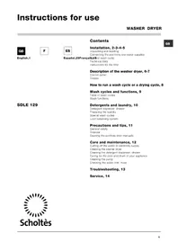
Installation, 2-3-4-5
natural_image
Pure technical diagram of a mechanical or electrical component with no visible text, numbers, or symbols.natural_image
Diagram of a washing machine with a circular component and a scroll wheel, showing rotational motion (no text or symbols)natural_image
Technical diagram of a mechanical component with labeled section A (no text or symbols beyond label)natural_image
Diagram of a mechanical device with a valve and handle, showing rotational motion (no text or symbols)natural_image
Diagram of a pipe connection with a connector, showing fluid flow and support structure (no text or labels)natural_image
Diagram of a rectangular appliance with a scroll wheel and directional arrows indicating motion (no text or symbols)E
Accessoires montage porte (Fig.1-2-3-4-5).
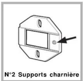
Fig. 1

natural_image
Technical drawing of a mechanical flange component with bolt holes and central bore (no text or symbols)Butoir aimant
natural_image
Technical line drawing of a mechanical component with rounded corners and a central square (no text or symbols)Fig. 3 Fig. 4

natural_image
Pure technical diagram showing a mechanical component with directional arrows, no text or symbols presentFig. 8 Fig. 9
natural_image
Diagram showing a mechanical component with an inset view of a cylindrical part labeled 'GLY' (no text or symbols present)Causes / Solutions possibles:
Unpacking and levelling, 18
Electric and water connections, 18-19
The first wash cycle, 19
Technical details, 19
Instructions for the fitter, 20-21
Washer-dryer description, 22-23
Control panel, 22
Display, 23
Starting and Programmes, 24
Briefly: how to start a programme, 24
Programme table, 24
MLSE 129
Setting the temperature, 25
Setting the spin cycle, 25
Options, 25
Drying, 26
Detergents and laundry, 27
Detergent dispenser, 27
Bleach cycle, 27
Preparing your laundry, 27
Special items, 27
Woolmark Platinum Care, 27
Precautions and advice, 28
General safety, 28
Disposal, 28
Saving energy and respecting the environment, 28
Care and maintenance, 29
Cutting off the water or electricity supply, 29
Cleaning your appliance, 29
Cleaning the detergent dispenser, 29
Caring for your appliance door and drum, 29
Cleaning the pump, 29
Checking the water inlet hose, 29
Troubleshooting, 30
Service, 31
Before calling for Assistance, 31

GB
!Keep this instruction manual in a safe place for future reference. Should the appliance be sold, transferred or moved, make sure the instruction manual accompanies the Washer-dryer to inform the new owner as to its operation and features.
!Read these instructions carefully: they contain vital information on installation, use and safety.
Unpacking and levelling
Unpacking
- Unpack the Washer-dryer.
- Check whether the Washer-dryer has been damaged during transport. If this is the case, do not install it and contact your retailer.

natural_image
Pure technical diagram of a mechanical or electrical component with no visible text, numbers, or symbols.-
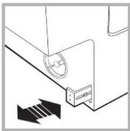
Remove the four protective screws and the rubber washer with the respective spacer, situated on the rear of the appliance (see figure).
-
Seal the gaps using the plastic plugs provided.
- Keep all the parts: you will need them again if the Washer-dryer needs to be moved to another location.
!Packaging materials are not children's toys.
Levelling
- Install the Washer-dryer on a flat sturdy floor, without resting it up against walls, furniture cabinets or other.
natural_image
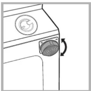
Line drawing of a washing machine with a circular logo and a scroll wheel (no text or symbols)- If the floor is not perfectly level, compensate for any unevenness by tightening or loosening the adjustable front feet (see figure); the angle of inclination, measured according to the worktop, must not exceed 2^ .
Levelling your appliance correctly will provide it with stability and avoid any vibrations, noise and shifting during operation. If it is placed on a fitted or loose carpet, adjust the feet in such a way as to allow enough room for ventilation beneath the Washer-dryer.
Electric and water connections
Connecting the water inlet hose
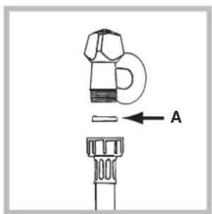
- Insert seal A into the end of the inlet hose and screw the latter onto a cold water tap with a 3/4 gas threaded mouth (see figure). Before making the connection, allow the water to run freely until it is perfectly clear.
natural_image
Diagram of a mechanical valve mechanism with rotation arrow (no text or symbols)-
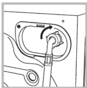
Connect the other end of the water inlet hose to the Washer-dryer, screwing it onto the appliance's cold water inlet, situated on the top right-hand side on the rear of the appliance (see figure).
-
Make sure there are no kinks or bends in the hose.
!The water pressure at the tap must be within the values indicated in the Technical details table (on the next page).
!If the water inlet hose is not long enough, contact a specialist store or an authorised serviceman.
Connecting the drain hose
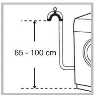
Connect the drain hose, without bending it, to a draining duct or a wall drain situated between 65 and 100 cm from the floor;

natural_image
Diagram of a pipe connection with a magnified inset showing a device (no text or symbols)alternatively, place it over the edge of a basin, sink or tub, fastening the duct supplied to the tap (see figure). The free end of the hose should not be underwater.
! We advise against the use of hose extensions; in case of absolute need, the extension must have the same diameter as the original hose and must not exceed 150 cm in length.
Electric connection
Before plugging the appliance into the mains socket, make sure that:
- the socket is earthed and in compliance with the applicable law;
- the socket is able to sustain the appliance's maximum power load indicated in the Technical details table (on the right);
- the supply voltage is included within the values indicated on the Technical details table (on the right);
- the socket is compatible with the washing machine's plug. If this is not the case, replace the socket or the plug.
! The Washer-dryer should not be installed in an outdoor environment, not even when the area is sheltered, because it may be very dangerous to leave it exposed to rain and thunderstorms.
! When the Washer-dryer is installed, the mains socket must be within easy reach.
! Do not use extensions or multiple sockets.
! The power supply cable must never be bent or dangerously compressed.
! The power supply cable must only be replaced by an authorised serviceman.
Warning! The company denies all liability if and when these norms are not respected.
The first wash cycle
Once the appliance has been installed, and before you use it for the first time, run a wash cycle with detergent and no laundry, setting the 90°C programme without a pre-wash cycle.
| Technical details | |
| Model | MLSE 129 |
| Dimensions | 59.5 cm wide81,5 cm high54 cm deep |
| Capacity | from 1 to 5 kg for the wash programme; from 1 to 4 kg for the drying programme |
| Electric connections | voltage 220/230 Volts 50 Hzmaximum absorbed power 1850 W |
| Water connections | maximum pressure 1 MPa (10 bar)minimum pressure 0.05 MPa (0.5 bar)drum capacity 46 litres |
| Spin speed | up to 1200 rpm |
| Control programmes according to IEC456 directive | Wash: programme 3; temperature 60°C; run with a load of 5 kg.Drying: first drying cycle performed with a 1 kg load, by selecting a drying time of 40 min;Second drying cycle performed with a 4 kg load, selecting the maximum drying level__≡ . |
| This appliance is compliant with the following European Community Directives:- 73/23/CEE of 19/02/73 (Low Voltage) and subsequent amendments- 89/336/CEE of 03/05/89(Electromagnetic Compatibility) and subsequent amendments- 2002/96/CE | |
Instructions for the fitter
Mounting the wooden panel onto the door and inserting the machine into cabinets:
In the case where the machine must be shipped for final installation after the wooden panel has been mounted, we suggest leaving it in its original packaging. The packaging was designed to make it possible to mount the wooden panel onto the machine without removing it completely (see figures below).
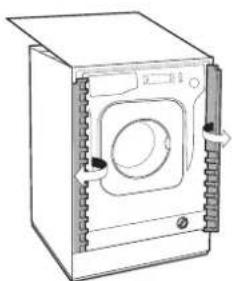
The wooden panel that covers the face of the machine must not be less than 18 mm in thickness and can be hinged on either the right or left. For the sake of practicality when using the machine, we recommend that the panel be hinged on the same side as the door for the machine itself - the left.
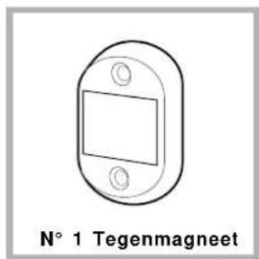
Door Mounting Accessories (Fig. 1-2-3-4-5).
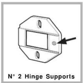
Fig. 1

Fig. 2

natural_image
Technical drawing of a flange component with mounting holes and a central circular recess (no text or symbols)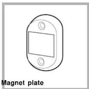
natural_image
Simple line drawing of a rectangular magnet plate with two mounting holes (no text or symbols)Fig. 3 Fig. 4
natural_image
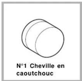
Simple line drawing of a cylindrical object labeled 'N° 1 Rubber plug' (no other text or symbols)Fig. 5
natural_image
Simple line drawing of an oval-shaped device with three circular holes and a rectangular slot, labeled 'N° 1 Spacer' below (no other text or symbols)Fig. 4/B
- No. 6 type A self-threading screws, l=13 mm.
- No. 2 type B metric, countersunk screws, l=25; for fastening the magnet plate to the cabinet.
- No. 4 type C metric screws, l=15 mm; for mounting the hinge supports to the cabinet.
- No. 4 type D metric screws, l = 7 mm; for mounting the hinges on the supports.
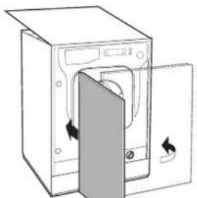
Mounting the Parts onto the Face of the Machine.
- Mount the hinge supports onto the face of the machine, positioning the hole indicated by the arrow in fig. 1 towards the inside of the face and using the type C screws.
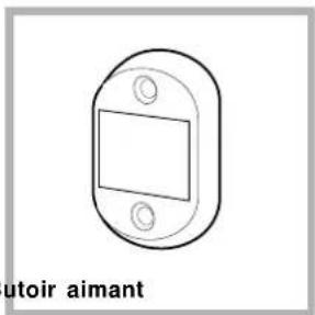
- Mount the magnetic plate on the opposite side, at the top, using the two type B screws.
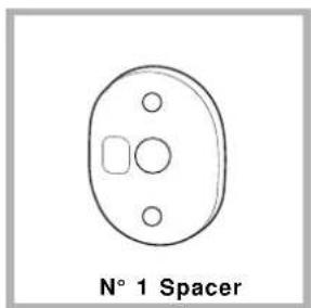
- Place the spacer illustrated in fig. 4/B between the appliance front and the magnet receiver.
Using the Drilling Template.
- To trace the positions of the holes on the left-hand side of the panel, align the drilling template to the top left side of the panel using the lines traced on the extremities as a reference.
- To trace the positions of the holes on the right-hand side of the panel, align the drilling template to the top right side of the panel.
- Use an appropriately sized router to mill the holes for the two hinges, the rubber plug and the magnet.
Mounding the Parts onto the Wooden Panel (Door).
- Insert the hinges into the holes (the movable part of the hinge must be positioned facing away from the panel) and fasten them with the 4 type A screws.
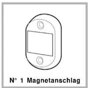
- Insert the magnet into the top hole on the opposite side of the hinges and fasten it with the two type B screws.
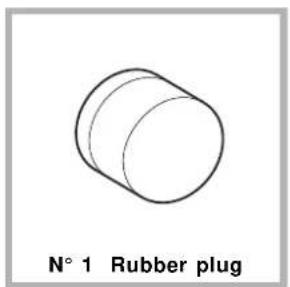
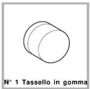
- Insert the rubber plug into the bottom hole.
The panel is now ready to be mounted onto the machine.
Mounting the Panel into the machine.
Insert the nib of the hinge (indicated by the arrow in fig. 2) into the hole for the hinge and push the panel towards the front of the machine. Fasten the two hinges with the type D screws.
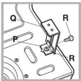
Fastening the plinth guide.
If the machine is installed at the end of a set of modular cabinets, mount either one or both of the guides for the base molding (as shown in fig. 8). Adjust them for depth based on the position of the base molding, and, if necessary, fasten the base to the guides (fig. 9).
This is how to assemble the plinth guide (fig. 8):
Fasten angle P using screw R, insert plinth guide Q into the special slot and once it is in the desired position, lock it in place using angle P and screw R.
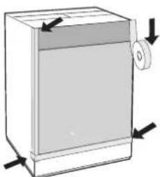
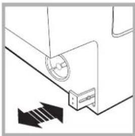
Inserting the machine into the Cabinet.
- Push the machine into the opening, aligning it with the cabinets (fig. 6).
- Regulate the adjustable feet to raise the machine to the appropriate height.
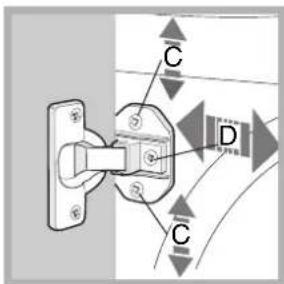
- To adjust the position of the wooden panel in both the vertical and horizontal directions, use the C and D screws, as shown in fig. 7.
Important: close the lower part of the appliance front by ensuring that the plinth rests against the floor.
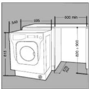
Fig. 6 Fig. 7

The Ground Truth image displays a single, solid horizontal line. According to Rule 2 (UNDERSCORE & LINE RULES), this is a stylistic or background line, not a placeholder underscore. Therefore, the OCR result must ignore it and output nothing or only meaningful text. The provided OCR content is "____", which consists of four underscores. This is an incorrect interpretation of the line as a placeholder, violating the rule that stylistic lines must be ignored. The OCR has hallucinated placeholder underscores where none exist in the GT. Hence, the OCR result is inconsistent with the Ground Truth.
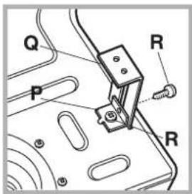
Fig. 8 Fig. 9

natural_image
Diagram of a mechanical or electrical component with directional arrows indicating movement or force (no text or symbols)Accessories provided for the height adjustment.
The following can be found inside the polystyrene lid (fig. 10): 2 crossbars (G), 1 strip (M)

the following can be found inside the appliance drum:
4 additional feet (H),
4 screws (I),
4 screws (R),
4 nuts (L),
2 plinth guides (Q)
Fig. 10
Adjusting the appliance height.
The height of the appliance can be adjusted (from 815 mm to 835 mm), by turning the 4 feet.
Should you require the appliance to be placed higher than the above height, you need to use the following accessories to raise it to up to 870 mm:
the two crossbars (G); the 4 feet (H); the 4 screws (I); the 4 nuts (L) then perform the following operations (fig. 11): remove the 4 original feet, place a crossbar G at the front of the appliance, fastening it in place using screws I (screwing them in where the original feet were) then insert the new feet H. Repeat the same operation at the back of the appliance.
Now adjust feet H to raise or lower the appliance from 835 mm to 870 mm.
Once you have reached the desired height, lock nuts L onto crossbar G.
To adjust the appliance to a height between 870 mm and 900 mm, you need to mount strip M, adjusting feet H to the required height.
Insert the strip as follows:
loosen the three screws N situated at the front of the Top cover of the appliance, insert strip M as shown in fig. 12, then fasten screws N.
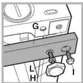
Fig. 11
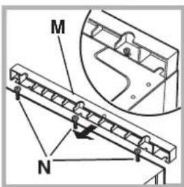
Fig. 12
Washer-dryer description
GB
Control panel
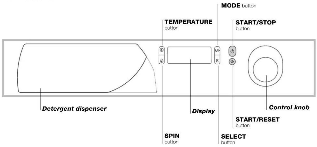
Detergent dispenser to add detergent and fabric softener (see page 27).
TEMPERATURE button to adjust the wash temperature (see page 25).
SPIN button to adjust the spin speed or exclude it altogether (see page 25).
Display to programme the Washer-dryer and follow the wash cycle progress (see opposite page).
MODE button to choose the options for the appliance personalisation (see page 25).
SELECT button to set the options for the appliance personalisation (see page 25).
START/STOP button to turn the Washer-dryer on and off.
START/RESET button to start the programmes or cancel any incorrect settings.
Control knob to select the wash programmes. The retractable control knob: press the centre of the knob for it to pop out. The knob stays still during the cycle.
Display
In addition to being a practical tool to programme your appliance (see page 25), the display provides useful information concerning the wash cycle and status.
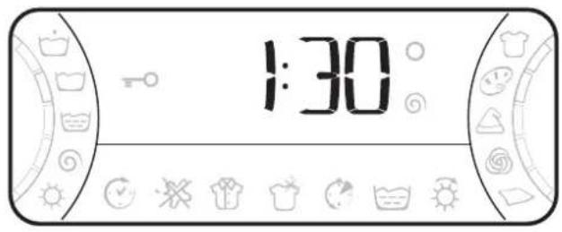
Once you have pressed the START/RESET button to start the programme, the display will indicate the amount of time left until the end of the wash cycle. If a delayed start has been set (using the Delay Timer, see page 25), the delay time will be indicated on the display.
The following information is displayed during the wash cycle:

Cycle phase under way:

Pre-wash

pin cycle

Wash cycle

ying

Rinse

Fabric selected:

Cotton

bol

Colours

*

Synthetics

Personalisation options:
The enabled options are bordered by a frame. To choose the options, see page 25.
Door lock:
If the symbol is on, the Washer-dryer door is locked to prevent it from being opened accidentally. To avoid any damages, wait for the symbol to switch itself off before you open the appliance door.
At the end of the programme, the word END is displayed.
! In the event of an anomaly, an error code will appear, such as: F-01, which should be communicated to the Service Centre (see page 31).
Starting and Programmes
Briefly: starting a programme
- Turn the Washer-dryer on by pressing button ⏻.
- Load your laundry into the Washer-dryer and shut the appliance door.
-
Set the knob to the desired programme. The estimated duration of the selected programme is displayed. The temperature and spin speed are automatically set according to the programme (to change them, see page 25).
-
Add the detergent and any fabric softener (see page 27).
- Start he programme by pressing the START/RESET button.
To cancel it, keep the START/RESET button pressed for at least 2 seconds. -
When the programme has ended, the word END is displayed. Take out your laundry and leave the appliance door ajar to allow the drum to dry thoroughly.
-
Turn the Washer-dryer off by pressing button

Programme table
| Type of fabric and degree of soil | Program-mes | Wash temp. | Detergent | Fabric softener | Bleaching option/bleach | Cycle length (minutes) | Description of wash cycle | |
| Pre-wash | Wash | |||||||
| Cotton | ||||||||
| Extremely soiled whites (sheets, tablecloths, etc.) | 1 | 90°C | • • 137 | Pre-wash, wash cycle, rinse cycles, intermediate and final spin cycles | ||||
| Extremely soiled whites (sheets, tablecloths, etc.) | 2 | 90°C | • | Delicate/Traditional | 120 | Wash cycle, rinse cycles, intermediate and final spin cycles | ||
| Heavily soiled whites and fast colours | 3 | 60°C | • | Delicate/Traditional | 105 | Wash cycle, rinse cycles, intermediate and final spin cycles | ||
| Slightly soiled whites and delicate colours (shirts, jumpers, etc.) | 4 | 40°C | • | Delicate/Traditional | 72 | Wash cycle, rinse cycles, intermediate and final spin cycles | ||
| Drying cycle for cotton fabrics | 5 | |||||||
| Synthetics | ||||||||
| Heavily soiled fast colours (baby linen, etc.) | 6 | 60°C | • Delicate 77 | Wash cycle, rinse cycles, anti-crease or delicate spin cycle | ||||
| Fast colours (all types of slightly soiled garments) | 6 | 40°C | • Delicate 62 | Wash cycle, rinse cycles, anti-crease or delicate spin cycle | ||||
| Heavily soiled fast colours (baby linen, etc.) | 7 | 50°C | • Delicate 73 | Wash cycle, rinse cycles, anti-crease or delicate spin cycle | ||||
| Delicate colours (all types of slightly soiled garments) | 8 | 40°C | • Delicate 58 | Wash cycle, rinse cycles, anti-crease or delicate spin cycle | ||||
| Delicate colours (all types of slightly soiled garments) | 9 | 30°C | • 30 | Wash cycle, rinse cycles and delicate spin cycl | ||||
| Drying cycle for synthetic fabrics | 10 | |||||||
| Delicate | ||||||||
| Wool | 11 | 40°C | • Delicate 50 | Wash cycle, rinse cycles and delicate spin cycle | ||||
| Very delicate fabrics (curtains, silk, viscose, etc.) | 12 | 30°C | • 45 | Wash cycle, rinse cycles, anti-crease or draining cycle | ||||
| Drying cycle for delicate fabrics | 13 | |||||||
| PARTIAL PROGRAMMES | ||||||||
| Delicate rinse cycle | 14 | • • Rinse cycles, anti-crease or draining | ||||||
| Delicate spin cycle | 15 | Draining and delicate spin cycle | ||||||
| Draining | 16 | Draining | ||||||
Notes
For the anti-crease function: see Easy iron, opposite page. The information contained in the table is purely indicative.
Special programme
Daily 30' (programme 9 for Synthetics) is designed to wash lightly soiled garments in a short amount of time: it only lasts 30 minutes and allows you to save on both time and energy. By setting this programme (9 at 30°C), you can wash different fabrics together (except for woollen and silk items), with a maximum load of 3 kg. We recommend the use of liquid detergent.
Personalisations
Setting the temperature
Press button and the maximum temperature allowed for the programme set will be displayed. Press the same button to lower this temperature. OFF indicates a cold wash.
The temperature adjustment is enabled with all wash programmes.
Setting the spin cycle
Press button and the maximum spin speed allowed for the programme set will be displayed. Press the same button to lower the value down to OFF, which indicates that the spin cycle has been excluded altogether (press it again to go back to the maximum value).
The spin cycle exclusion is indicated by symbol . The spin cycle setting is enabled with all the programmes except for 12 and the 16.
Options
The various wash options available with this Washer-dryer will make for the desired results, every time.
To select the various options, the following procedure should be followed at all times:
- Press the MODE button to scroll through the various options available; the enabled symbol will flash.
- To select it, press the SELECT button, until the word ON is displayed (for the Delay Timer the time will be displayed, for the Drying cycle the various drying levels: see table below).
- Confirm your setting by pressing the MODE button again: the symbol for the option will stop flashing on the display. The selected options can be seen on the display, as they are bordered by a frame.
| Option Effect Comments | Enabled with programmes: | ||
| Delay Timer | Delays the start of the wash by up to 24 hours. | Press (SELECT button) repeatedly until the desired delay is displayed. OFF indicates no delay has been set. | All |
| Bleaching | Bleaching cycle designed to remove the toughest stains. | Please remember to pour the bleach into extra compartment 4 (see page 27). This option is incompatible with the EASY IRON option. | 2, 3, 4, 6, 7, 8, 11, 14 |
| Easy iron | This option reduces the amount of creasing on fabrics, making them easier to iron. | If you set this option, programmes 6, 7, 8, 12 and 14 will be suspended, leaving the laundry to soak (Anti-crease) and icon will flash:- to conclude the cycle, press the START/RESET button;- to run the draining cycle alone, set the knob to the relative symbol "16" and press the START/RESET button. This option is incompatible with the BLEACHING option. | All programmes except for 1, 2, 9, 11, 16 |
| Super Wash | Allows for an impeccable wash, visibly whiter than a standard Class A wash. | This option is incompatible with the RAPID option. | 1, 2, 3, 4, 6, 7, 8 |
| Rapid | Cuts the duration of the wash cycle by 30%. | This option is incompatible with the SUPER WASH option. | 1, 2, 3, 4, 6, 7, 8 |
| Extra Rinse | Increases the efficiency of the rinse. | Recommended when the appliance has a full load or with large quantities of detergent. | 1, 2, 3, 4, 6, 7, 8, 14 |
| Press (SELECT button) repeatedly until the desired drying type is displayed.- Iron : slightly damp clothes, easy to iron.- Wardrobe : dry clothes to put away.- Extra dry : very dry clothes, recommended for towelling and bathrobes.- 40 minutes. | All programmes except for 12 and 16 | ||
| Drying | A cooling stage is foreseen at the end of the drying cycle. | ||
Drying
Table of drying times
| Fabric type | Load type Max. | load (kg) Ex | — == ≡tra dry | — =Wardrobe | —Iron |
| Cotton, Linen | Clothing of different sizes | 4 | 130 | 120 | 110 |
| Cotton | Terry towels 4 | 30 | 120 | 110 | |
| Tantal, Cotton | Sheets, Shirts | 2,5 | 90 | 80 | 70 |
| Acrylics | Pyjamas, socks, etc. | 1 | 65 | 60 | 60 |
| Nylon | Slips, tights, stockings, etc. | 1 | 65 | 60 | 60 |
| Wool | Knitwear, Pullovers, etc. | 1 | 80 | 70 | 60 |
The data contained in the table are purely indicative.
If your laundry load to wash and dry is exceptionally in excess of the maximum load foreseen (see table opposite), perform the wash cycle, and when the programme is complete, divide up the garments and put part of them back in the drum. Now follow the instructions provided for a dry only cycle. Repeat this procedure for the remainder of the load.
Dry only
Set the PROGRAMME knob to one of the drying settings (5-10-13) depending on the type of fabric, then select the desired drying type.
Important:
- A spin cycle is carried out during the drying if you have set a cotton programme.
- If you set "spin cycle exclusion", you may not select a drying cycle.
If you wish to run a drying cycle, select the maximum spin speed available and then choose the type of drying required.
- For cotton loads of less than 1 Kg, use the drying programme designed for synthetic fabrics.
Detergent dispenser
Good washing results also depend on the correct dose of detergent: adding too much detergent won't necessarily make for a more efficient wash, and may in fact cause build up on the interior of your appliance and even pollute the environment.
Open up the detergent dispenser and pour in the detergent and fabric softener, as follows.
compartment 1: Detergent for pre-wash (powder)
Before pouring in the detergent, make sure that extra compartment 4 has been removed.
compartment 2: Detergent for the wash cycle (powder or liquid)
Liquid detergent should only be poured in immediately prior to the wash cycle start.
compartment 3: Additives (fabric softeners, etc.)
The fabric softener should not overflow from the grid. extra compartment 4: Bleach
! Do not use hand wash detergent because it may form too much foam.
Bleach cycle
! Traditional bleach should be used on sturdy white fabrics, and delicate bleach for coloured fabrics, synthetics and for wool.

natural_image
Diagram showing a mechanical component with an inset close-up of a cylindrical component labeled 'OUT' (no text or symbols beyond label)Place extra compartment 4, provided, into compartment 1. When pouring in the bleach, be careful not to exceed the "max" level indicated on the central pivot (see figure).
To run the bleach cycle alone, pour the bleach into extra compartment 4, set the “Delicate Rinse” programme “14” and enable the Bleaching option (see page 25).
To bleach during a wash cycle, pour in the detergent and fabric softener, set the desired programme and enable the Bleaching option (see page 25).
The use of extra compartment 4 excludes the possibility of using the pre-wash cycle. In addition, the bleach cycle cannot be run with programmes 12 (Silk) and Daily 30' (see page 24).
Preparing your laundry
- Divide your laundry according to:
- the type of fabric/the symbol on the label.
- the colours: separate coloured garments from whites.
- Empty all pockets and check for loose buttons.
- Do not exceed the weight limits stated below, which refer to the weight when dry: Sturdy fabrics: max 5 kg Synthetic fabrics: max 2.5 kg Delicate fabrics: max 2 kg Wool: max 1 kg
How much does your laundry weigh?
1 sheet 400-500 g
1 pillow case 150-200 g
1 tablecloth 400-500 g
1 bathrobe 900-1,200 g
1 towel 150-250 g
Special items
Curtains: fold curtains and place them in a pillow case or mesh bag. Wash them separately without exceeding half the appliance load. Use programme 12 which excludes the spin cycle automatically.
Quilted coats and windbreakers: if they are padded with goose or duck down, they can be machine-washed. Turn the garments inside out and load a maximum of 2-3 kg, repeating the rinse cycle once or twice and using the delicate spin cycle.
Trainers: remove any mud. They can be washed together with jeans and other tough garments, but not with whites.
Wool: for best results, use a specific detergent, taking care not to exceed a load of 1 kg.
Woolmark Platinum Care

WOOLMARK
PLATINUM
CARE
As gentle as a hand wash.
Scholtes sets a new standard of superior performance that has been endorsed by
The Woolmark Company with the prestigious Woolmark Platinum Care brand. Look for the Woolmark Platinum Care logo on the Washer-dryer to ensure you can safely and effectively wash wool garments labelled as "hand wash" (M.0303): Set programme 11 for all "Hand wash" garments, using the appropriate detergent.

! The Washer-dryer was designed and built in compliance with the applicable international safety regulations. The following information is provided for your safety and should consequently be read carefully.
General safety
- This appliance has been designed for non-professional, household use and its functions must not be changed.
- This Washer-dryer should only be used by adults and in accordance with the instructions provided in this manual.
- Never touch the Washer-dryer when barefoot or with wet or damp hands or feet.
- Do not pull on the power supply cable to unplug the appliance from the electricity socket. Pull the plug out yourself.
- Do not open the detergent dispenser while the appliance is in operation.
- Do not touch the drain water as it could reach very high temperatures.
- Never force the Washer-dryer door: this could damage the safety lock mechanism designed to prevent any accidental openings.
- In the event of a malfunction, do not under any circumstances touch internal parts in order to attempt repairs.
• Always keep children well away from the appliance while in operation. - The appliance door tends to get quite hot during the wash cycle.
- Should it have to be moved, proceed with the help of two or three people and handle it with the utmost care. Never try to do this alone, because the appliance is very heavy.
- Before loading your laundry into the washing machine, make sure the drum is empty.
- During the drying phase, the door tends to get quite hot.
- Do not use the appliance to dry clothes that have been washed with flammable solvents (e.g. trichlorethylene).
- Do not use the appliance to dry foam rubber or similar elastomers.
- Make sure that the water tap is turned on during the drying cycles.
- This washer-dryer can only be used to dry clothes which have been pre-washed in water.
Disposal
- Disposing of the packaging material: observe local regulations, so the packaging can be re-used.
- The European Directive 2002/96/EC on Waste Electrical and Electronic Equipment, requires that old household electrical appliances must not be
disposed of in the normal unsorted municipal waste stream. Old appliances must be collected separately in order to optimise the recovery and recycling of the materials they contain and reduce the impact on human health and the environment. The crossed out "wheeled bin" symbol on the product reminds you of your obligation, that when you dispose of the appliance it must be separately collected.
Consumers should contact their local authority or retailer for information concerning the correct disposal of their old appliance.
Saving energy and respecting the environment
Environmentally-friendly technology
If you only see a little water through your appliance door, this is because thanks to the latest Scholtes technology, your Washer-dryer only needs less than half the amount of water to get the best results: an objective reached to respect the environment.
Saving on detergent, water, energy and time
- To avoid wasting resources, the Washer-dryer should be used with a full load. A full load instead of two half loads allows you to save up to 50% on energy.
- The pre-wash cycle is only necessary on extremely soiled garments. Avoiding it will save on detergent, time, water and between 5 and 15% energy.
- Treating stains with a stain remover or leaving them to soak before washing will cut down the need to wash them at high temperatures. A programme at 60°C instead of 90°C or one at 40°C instead of 60°C will save up to 50% on energy.
- Use the correct quantity of detergent depending on the water hardness, how soiled the garments are and the amount of laundry you have, to avoid wastage and to protect the environment: despite being biodegradable, detergents do contain ingredients that alter the natural balance of the environment. In addition, avoid using fabric softener as much as possible.
- If you use your Washer-dryer from late in the afternoon until the early hours of the morning, you will help reduce the electricity board's peak load. The Delay Timer option (see page 25) helps to organise your wash cycles accordingly.
- If your laundry has to be dried in a tumble dryer, select a high spin speed. Having the least water possible in your laundry will save you time and energy in the drying process.
Cutting off the water or electricity supply
- Turn off the water tap after every wash. This will limit the wear of your appliance's water system and also prevent leaks.
- Unplug your appliance when cleaning it and during all maintenance operations.
Cleaning your appliance
The exterior and rubber parts of your appliance can be cleaned with a soft cloth soaked in lukewarm soapy water. Do not use solvents or abrasives.
Cleaning the detergent dispenser
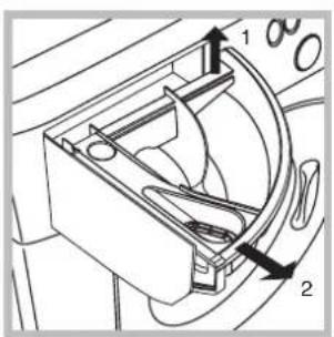
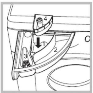
Remove the dispenser by raising it and pulling it out (see figure). Wash it under running water; this operation should be repeated frequently.
Caring for your appliance door and drum
• Always leave the appliance door ajar to prevent unpleasant odours from forming.
Cleaning the pump
The Washer-dryer is fitted with a self-cleaning pump that does not require any maintenance.
Checking the water inlet hose
Check the water inlet hose at least once a year. If you see any cracks, replace it immediately: during the wash cycles, water pressure is very strong and a cracked hose could easily split open.
! Never use hoses that have already been used.
Your Washer-dryer could fail to work. Before calling for Assistance (see page 31), make sure the problem can't easily be solved by consulting the following list.
| Problem | Possible causes/Solution: |
| The Washer-dryer won't start. | · The appliance is not plugged into the socket, or not enough to make contact.· There has been a power failure. |
| The wash cycle won't start. | · The appliance door is not shut properly (the word DOOR is displayed).· The button has not been pressed.· The START/RESET button has not been pressed.· The water tap is not turned on.· A delayed start has been set (using the Delay Timer, see page 25). |
| The Washer-dryer fails to load water (The wording H2O is displayed). | · The water inlet hose is not connected to the tap.· The hose is bent.· The water tap is not turned on.· There is a water shortage.· The water pressure is insufficient.· The START/RESET button has not been pressed. |
| The Washer-dryer continuously loads and unloads water. | · The drain hose is not fitted between 65 and 100 cm from the floor (see page 19).· The free end of the hose is underwater (see page 19).· The wall drainage system doesn't have a breather pipe. If the problem persists even after these checks, turn off the water tap, switch the appliance off and call for Assistance. If the dwelling is on one of the upper floors of a building, there may be drain trap problems causing the Washer-dryer to load and unload water continuously. In order to avoid such an inconvenience, special anti-drain trap valves are available in shops. |
| The Washer-dryer does not drain or spin. | · The programme does not foresee the draining: some programmes require enabling the draining manually (see page 24).· The Easy iron option is enabled: to complete the programme, press the START/RESET button (see page 25).· The drain hose is bent (see page 19).· The drain duct is clogged. |
| The Washer-dryer vibrates too much during the spin cycle. | · The drum was not unblocked correctly during installation (see page 18).· The Washer-dryer is not level (see page 18).· The Washer-dryer is closed in between furniture cabinets and the wall (see page 18). |
| The Washer-dryer leaks. | · The water inlet hose is not screwed on correctly (see page 18).· The detergent dispenser is obstructed (to clean it, see page 29).· The drain hose is not secured properly (see page 19). |
| There is too much foam. | · The detergent is not suitable for machine washing (it should bear the definition "for Washing-machine" or "hand and machine wash", or the like).· You used too much detergent. |
| The washer-dryer does not dry. | · The appliance is not plugged into the socket, or not enough to make contact.· There has been a power failure.· The appliance door is not shut properly.· A delayed start has been set (using the Delay Timer, see page 25). |
Before calling for Assistance:
- Check whether you can solve the problem on your own (see page 30);
- Restart the programme to check whether the problem has been solved;
- If this is not the case, contact an authorised Technical Service Centre on the telephone number provided on the guarantee certificate.
!Always request the assistance of authorised servicemen.
Notify the operator of:
• the type of problem;
• the appliance model (Mod.);
• the serial number (S/N).
This information can be found on the data plate situated on the rear of the Washer-dryer.
GB

Deutsch
INHALTSVERZEICHNIS
Installation, 34-35
natural_image
Pure technical diagram of a mechanical or electrical component with no visible text, numbers, or symbols.natural_image
Diagram of a washing machine door with a circular button and a scroll wheel, showing a rotational arrow (no text or symbols)natural_image
Diagram of a mechanical component with a labeled arrow and section view (no text or symbols present)natural_image
Diagram of a mechanical device with a valve and handle, showing rotational motion (no text or symbols)natural_image
Diagram of a pipe connection with a magnified inset showing a device (no text or symbols present)natural_image
Simple line drawing of a rectangular box with a handle, no text or symbols presentA

natural_image
Line drawing of a single washing machine with open lid and side panel, showing front panel and side buttons (no text or symbols)B
natural_image
Line drawing of a front-loading washing machine with side-mounted buttons and ventilation slots (no text or symbols)C

natural_image
Diagram of a door switch with directional arrows indicating rotation or movement (no text or symbols)D

natural_image
Simple line drawing of a rectangular box with a circular button and directional arrows indicating flow or movement (no text or symbols)E
natural_image
Mechanical bracket assembly diagram labeled N° 2 Scharnier, showing mounting holes and a downward arrow (no text or symbols on the diagram itself)Abb. 2

natural_image
Technical drawing of a flange with a central circular hole and two mounting holes (no text or symbols)Abb. 3 Abb. 4
natural_image
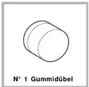
Simple line drawing of a cylindrical object labeled 'N° 1 Gummidübel' (no other text or symbols)Abb. 5


natural_image
Diagram showing a mechanical component with directional arrows indicating movement or force (no text or symbols)Abb. 8 Abb. 9
natural_image
Diagram showing a mechanical component with an inset close-up of a cylindrical part (no text or symbols)natural_image
Pure technical diagram of a mechanical or electrical component with no visible text, numbers, or symbols.natural_image
Diagram of a washing machine with a circular button and a scroll wheel, showing rotational motion (no text or symbols)natural_image
Technical line drawing of a mechanical component with a valve and handle (no text or symbols)natural_image
Diagram of a pipe connection with a magnified inset showing a device (no text or symbols present)natural_image
Simple line drawing of a rectangular box with a handle, no text or symbols presentA

natural_image
Line drawing of a washing machine with a door open, showing a circular vent and side buttons (no text or symbols)B

natural_image
Line drawing of a washing machine with side panels and buttons (no text or symbols)C
natural_image
Diagram of a washing machine with a door and side panel, showing internal components and directional arrows (no text or symbols)D
natural_image
Simple line drawing of a rectangular box with a side panel and directional arrows indicating flow or movement (no text or symbols)E
natural_image
Mechanical component diagram labeled N° 2 Scharnier, showing a bracket with mounting holes and a black arrow indicating direction (no text or symbols on the diagram itself)Afb. 2
natural_image
Technical drawing of a flange component with circular center and four mounting holes (no text or symbols)Afb. 3 Afb. 4
natural_image
Simple line drawing of a Tegenmagneet device with rounded corners and a rectangular slot (no text or symbols)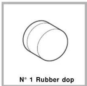
natural_image
Simple line drawing of a cylindrical object labeled 'N° 1 Rubber dop' (no other text or symbols)Afb. 5

natural_image
Simple line drawing of a circular object with three holes and a small square cutout, labeled 'N° 1 Distantiestuk' below (no other text or symbols)Afb. 4/B

Afb. 8 Afb. 9

natural_image
Diagram showing a mechanical component with a circular component and directional arrows indicating motion (no text or symbols)natural_image
Diagram showing a mechanical component with an inset close-up of a cylindrical component labeled 'BUT' (no text or symbols on the main diagram)natural_image
Technical diagram of a mechanical or electrical component with concentric rings and directional arrows, no visible text or symbols.natural_image
Line drawing of a washing machine with a circular button and a scroll wheel, showing a rotational arrow (no text or symbols)natural_image
Technical diagram of a mechanical component with labeled section A (no text or symbols beyond label)natural_image
Line drawing of a mechanical component with a valve and handle (no text or symbols)natural_image
Diagram of a pipe connection with a magnified inset showing a device (no text or symbols present)Fig. 1

Fig. 2

natural_image
Technical drawing of a flange component with concentric circular features and mounting holes (no text or symbols)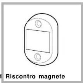
Fig. 3 Fig. 4
natural_image
Simple line drawing of a cylindrical object labeled 'N° 1 Tassello in gomma' (no other text or symbols)Fig. 5
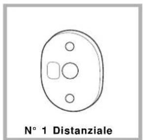
Fig. 4/B
Fig. 6 Fig. 7

natural_image
Diagram of a mechanical or electrical component with directional arrows indicating movement or force (no text or symbols)Fig. 8 Fig. 9
natural_image
Diagram showing a mechanical component with an inset close-up of its cylindrical part (no text or symbols)is a brand of the Merloni Elettrodomestici Group
Indesit Company
Viale Aristide Merloni, 47
60044 Fabriano (AN) Italy
Tel. +39 0732 6611
www.scholtes.com
This document is printed by
Xerox Business Service - Docutech 04/05
Document number: 195044723.02
In conformity with our general conditions of sale, we reserve the right to modify our models without notice and this booklet can in no way be considered as a binding document.


- Installation, 2-3-4-5
- Washer-dryer description, 22-23
- Starting and Programmes, 24
- Detergents and laundry, 27
- Precautions and advice, 28
- Care and maintenance, 29
- Troubleshooting, 30
- Service, 31
- Unpacking and levelling
- Unpacking
- Levelling
- Electric and water connections
- Connecting the water inlet hose
- Connecting the drain hose
- Electric connection
- The first wash cycle
- Instructions for the fitter
- Mounting the wooden panel onto the door and inserting the machine into cabinets:
- Mounting the Parts onto the Face of the Machine.
- Using the Drilling Template.
- Mounding the Parts onto the Wooden Panel (Door).
- Mounting the Panel into the machine.
- Fastening the plinth guide.
- Inserting the machine into the Cabinet.
- Accessories provided for the height adjustment.
- Adjusting the appliance height.
- Washer-dryer description
- Display
- Cycle phase under way:
- Fabric selected:
- Personalisation options:
- Door lock:
- Starting and Programmes
- Briefly: starting a programme
- Notes
- Special programme
- Personalisations
- Setting the temperature
- Setting the spin cycle
- Options
- Drying
- Dry only
- Important:
- Detergent dispenser
- compartment 1: Detergent for pre-wash (powder)
- compartment 2: Detergent for the wash cycle (powder or liquid)
- compartment 3: Additives (fabric softeners, etc.)
- Bleach cycle
- Preparing your laundry
- How much does your laundry weigh?
- Special items
- Woolmark Platinum Care
- As gentle as a hand wash.
- General safety
- Disposal
- Saving energy and respecting the environment
- Environmentally-friendly technology
- Saving on detergent, water, energy and time
- Cutting off the water or electricity supply
- Cleaning your appliance
- Cleaning the detergent dispenser
- Caring for your appliance door and drum
- Cleaning the pump
- Checking the water inlet hose
- Before calling for Assistance:
- Notify the operator of:
- INHALTSVERZEICHNIS
- Installation, 34-35
- Indesit Company
Brand : SCHOLTES
Model : MLSE 129
Category : Washing machine