IT 500 - Boiler A.O. Smith - Free user manual and instructions
Find the device manual for free IT 500 A.O. Smith in PDF.



| Product type | Storage water heater (sanitary hot water tank) |
| Brand | A.O. Smith |
| Model | IT 500 |
| Capacity | 473 litres |
| Empty weight | 180 kg |
| Max. operating pressure tank | 10 bar (1000 kPa) |
| Max. operating pressure heat exchanger | 16 bar (1600 kPa) |
| Max. temperature tank | 95 °C |
| Max. temperature heat exchanger | 110 °C |
| Heat exchanger power (coil) | 100 kW |
| Primary flow (80/60 °C) | 4300 l/h |
| Total height | 2040 mm |
| Diameter | 720 mm |
| Cold water connection | R 2" |
| Hot water connection | R 2" |
| Heat exchanger connection (inlet/outlet) | Rp 1" |
| Number of anodes | 1 |
| Tank material | Vitrified steel |
| Power supply | Indirect via heat exchanger (primary circuit) |
| Main functions | Production and storage of sanitary hot water |
| Maintenance and cleaning | Periodic descaling of the tank, inspection and replacement of anodes |
| Safety | Mandatory safety group, recommended thermal valve, cathodic protection |
| Tank warranty | 3 years (1 year if softened water) |
| Parts warranty | 1 year |
Frequently Asked Questions - IT 500 A.O. Smith
User questions about IT 500 A.O. Smith
0 question about this device. Answer the ones you know or ask your own.
Ask a new question about this device
Download the instructions for your Boiler in PDF format for free! Find your manual IT 500 - A.O. Smith and take your electronic device back in hand. On this page are published all the documents necessary for the use of your device. IT 500 by A.O. Smith.
USER MANUAL IT 500 A.O. Smith
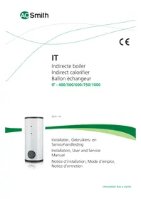
IT - 400/500/600/750/1000
0310 110

natural_image
White cylindrical device with black buttons and two dots on top (no visible text or symbols)Installation, User and Service
Manual
line
| X | Line 1 | Line 2 | Line 3 | |----|--------|--------|--------| | 0 | 0 | 0 | 0 | | 1 | 0.5 | 0.6 | 0.4 | | 2 | 1 | 1.2 | 0.8 | | 3 | 1.5 | 1.8 | 1.2 | | 4 | 2 | 2.5 | 1.6 | | 5 | 2.5 | 3 | 2 | | 6 | 3 | 3.5 | 2.4 | | 7 | 3.5 | 4 | 2.8 | | 8 | 4 | 4.5 | 3.2 | | 9 | 4.5 | 5 | 3.6 | | 10 | 5 | 5.5 | 4 | | 11 | 5.5 | 6 | 4.4 | | 12 | 6 | 6.5 | 4.8 | | 13 | 6.5 | 7 | 5.2 | | 14 | 7 | 7.5 | 5.6 | | 15 | 7.5 | 8 | 6 | | 16 | 8 | 8.5 | 6.4 | | 17 | 8.5 | 9 | 6.8 | | 18 | 9 | 9.5 | 7.2 | | 19 | 9.5 | 10 | 7.6 | | 20 | 10 | 10.5 | 8 | | 21 | 10.5 | 11 | 8.4 | | 22 | 11 | 11.5 | 8.8 | | 23 | 11.5 | 12 | 9.2 | | 24 | 12 | 12.5 | 9.6 | | 25 | 12.5 | 13 | 10 | | 26 | 13 | 13.5 | | | 27 | 13.5 | | | | 28 | | | | | 29 | | | | | 30 | | | | | Note: The actual values for Line 1, Line 2, and Line 3 are not provided in the code snippet. The actual values for Line 1, Line 2, and Line 3 are estimated based on the provided code snippet in the code.Inhoudsopgave / Table of contents / Table des matières
NL
This manual consists out of 3 languages.
1 - NL Handleiding IT 400 t/m 1000 5
2 - UK Manual IT 400 till 1000 19
3 - FR Notice IT 400 à 1000 35
FR
Copyright © 2011 A.O. Smith Water Products Company
A.O. Smith Water Products Company
Postbus 70
5500 AB Veldhoven
Nederland
Telefoon: (gratis) 008008 - AOSMITH
0800 - 267 64 84
Specifications water
IMD-0272
2 Installatie
| Read this manual carefully | WarningRead this manual carefully before starting the water heater. Failure to read the manual and to follow the printed instructions may lead to personal injury and damage to the water heater. |
| Copyright © 2011 A.O. Smith Water Products CompanyAll rights reserved.Nothing from this publication may be copied, reproduced and/or published by means of printing, photocopying or by whatsoever means, without the prior written approval of A.O. Smith Water Products Company.A.O. Smith Water Products Company reserves the right to modify specifications stated in this manual. | |
| Trademarks | Any brand names mentioned in this manual are registered trademarks of their respective owners. |
| Liability | A.O. Smith Water Products Company accepts no liability for claims from third parties arising from unauthorised use, use other than that stated in this manual, and use other than in accordance with the General Conditions registered at the Chamber of Commerce.Refer further to the General Conditions. These are available on request, free of charge.Although considerable care has been taken to ensure a correct and suitably comprehensive description of all relevant components, the manual may nonetheless contain errors and inaccuracies. Should you detect any errors or inaccuracies in the manual, we would be grateful if you would inform us. This helps us to further improve our documentation. |
| More information | If you have any comments or queries concerning specific aspects related to the water heater, then please do not hesitate to contact:A.O. Smith Water Products Company:PO Box 705500 AB VeldhovenThe NetherlandsTelephone: (free) 0870 - AOSMITH0870 - 267 64 84General: +31 40 294 25 00Fax: +31 40 294 25 39E-mail: info@aosmith.nlWebsite: www.aosmith.co.ukIn the event of problems with your gas, electricity or water supply connections, please contact the supplier/installation engineer of your installation. |
IT 400 / 500 / 600 / 750 / 1000
Table of contents
1 Technical specifications 23
1.1 Floor load 23
1.2 Water composition 23
1.3 Working clearance 23
1.4 General specifications 23
1.5 Dimensions 24
2 Installation 25
2.1 Installation diagram 25
2.2 Unvented water connections 26
2.3 Vented water connections 26
3 Maintenance 29
3.1 Preparation for maintenance 29
3.2 Water-side maintenance 29
4 Warranty 31
4.1 General warranty 31
4.2 Tank warranty 31
4.3 Conditions for installation and use 31
4.4 Exclusions 31
4.5 Scope of warranty 32
4.6 Claims 32
4.7 Obligations of A.O. Smith 32
IT 400 / 500 / 600 / 750 / 1000
1 Technical specifications
1.1 Floor load
Allow for the water heater's weight and the maximum floor load; refer to the table (1.4 "General specifications").
1.2 Water composition
The water heater is intended for heating drinking water. The drinking water must comply with the regulations governing drinking water for human consumption. The table gives an overview of the specifications.
Water specifications
| Water composition | |
| Hardness(alkaline earth ions) | >1,00 mmol/l:German hardness >5,6 °dHFranch hardness >10,0 °fHEnglish hardness >7,0 °eH |
| Conductivity | >125 μS/cm |
| Acidity (pH value) | 7,0 < pH value < 9,5 |
Note
If the water specifications deviate from those stated in the table, then the tank protection cannot be guaranteed (4"Warranty").
1.3 Working clearance
For access to the water heater, it is recommended that the following clearances are observed:
• around the anode connection: 100 cm.
• around the water heater: 50 cm.
• top of the water heater: 50 cm
1.4 General specifications
| Unit IT 400 IT 500 IT 600 IT 750 IT 1000 | ||||||
| Contents liters | 385 | 473 | 643 | 725 | 1007 | |
| Empty weight | kg | 139 | 180 | 241 | 254 | 336 |
| Max. operating pressure tank | kPa (bar) | 1000 (10) | 1000 (10) | 1000 (10) | 1000 (10) | 1000 (10) |
| Max. operating pressure heat excahnger | kPa (bar) | 1600 (16) | 1600 (16) | 1600 (16) | 1600 (16) | 1600 (16) |
| Max. water temperature tank | °C | 95 | 95 | 95 | 95 | 95 |
| Max. water temperature heat excahnger | °C | 110 | 110 | 110 | 110 | 110 |
| Anodes | - | 1 | 1 | 1 | 1 | 1 |
| Capacity heat exchanger | kW | 78 | 100 | 104 | 112 | 145 |
| Primary flow 80/60°C | l/h | 3354 | 4300 | 4472 | 4816 | 6235 |
| Pressure loss | mbar | 244 | 489 | 104 | 128 | 259 |
| Heat exchange surface | m^2 | 2,45 | 3,11 | 3,45 | 3,72 | 4,82 |
1.5 Dimensions
| Unit | IT 400 | IT 500 | IT 600 | IT 750 | IT 1000 | ||||||
| A | Total height | mm | 1705 | 2040 | 1835 | 2030 | 2000 | ||||
| D | Diameter mm | 720 | 720 | 910 | 910 | 1060 | |||||
| G | Height heat exchanger | outlet | mm | 255 | 255 | 305 | |||||
| H | Height heat exchanger inlet | mm | 1010 | 1205 | 1145 | 1205 | 1305 | ||||
| M | Height cold water inlet | mm | 70 | 70 | 85 | 85 | 95 | ||||
| N | Height warm water outlet | mm | mm | mm | 1650 | 1990 | 1795 | ||||
| O | Diameter inspection | opening | mm | 115 | 115 | 180 | 180 | ||||
| P | Height inspection | opening | mm | 330 | 330 | 415 | 415 | ||||
| R | Height top temp. sensor | sensor | connection | mm | 500 | 500 | 650 | ||||
| S | Height recirculationconnection | mm | 1095 | 1290 | 1235 | 1295 | 1395 | ||||
| T | Height bottom temp. sensor/T&P | mm | 1360 | 1700 | 1475 | 1670 | 1600 | ||||
| 1 | Cold water inlet | - | R 2 | R 2 | R 212 | R 212 | R 212 | ||||
| 2 | Warm water outlet | - | R 2 | R 2 | R 212 | R 212 | R 212 | ||||
| 3 | Heat exchanger outlet | - | Rp 1 | Rp 1 | Rp 1 | Rp 114 | Rp 114 | ||||
| 4 | Heat exchanger inlet | - | Rp 1 | Rp 1 | Rp 1 | Rp 114 | Rp 114 | ||||
| 7a | Bottom temp. sensor connection | - | Rp 34 | Rp 34 | Rp 34 | Rp 34 | Rp 34 | ||||
| 7b | Recirculation connection | - | Rp 34 | Rp 34 | Rp 34 | Rp 34 | Rp 34 | ||||
| 7c | Top temp. sensor/T&P connection | - | Rp 34 | Rp 34 | Rp 34 | Rp 34 | Rp 34 | ||||
| 8 | Anode connection | - | Rp 114 | Rp 114 | Rp 114 | Rp 114 | Rp 114 | ||||

IMD-0272
2 Installation
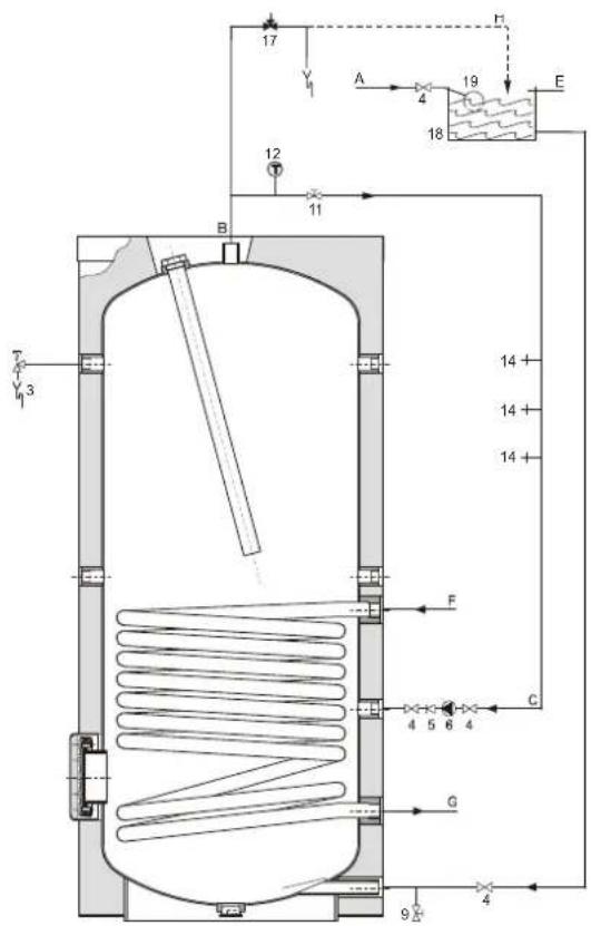
2.1 Installation diagram This figuur shows the installation diagram. This diagram is referred to in the sections describing the actual connection procedure.
VENTED
UNVENTED
IMD-0450 IMD-0449

Legend
- pressure relief valve
(mandatory if mains pressure is too high) - T&P-valve (mandatory)
- stop valve (recommended)
- non-return valve (mandatory)
- circulation pump (optioneel)
-
drain valve
-
service stop valve
water12. temperature gauge (optional)
- draw-off points
- expansion valve (mandatory)
- espansion vessel (mandatory)
- 3-way aeration valve (recommended)
- cold water head tank
- float switch
A. cold water supply
B. hot water supply
C. circulation pipe
E. overflow pipe
F. inlet heat exchanger
G. outlet heat exchanger
H. overflow protection
2.2 Unvented water connections
Warning
The installation should be carried out by a competent person, in compliance with general and locally applicable regulations.
2.2.1 Cold water side
See (A) in the installation diagram (2.1 "Installation diagram").
- Fit an approved stop valve (4) on the cold water side as required by the applicable regulations.
- The maximum working pressure of the water heater is 8 bar. Because the pressure in the water pipe at times can exceed 8 bar, you must fit an approved pressure-reducing valve (1).
- Fit a non-return valve (5) and an expansion vessel (16).
- Fit an expansion valve (15) and connect the overflow side to an open waste water pipe.
2.2.2 Hot Water side
See (B) in the installation diagram (2.1 "Installation diagram").
Note
Insulating long hot water pipes prevents unnecessary energy loss.
- Optional: fit a temperature gauge (12) so you can check the temperature of the tap water.
- Fit the T&P valve (3).
- Fit a stop valve (11) in the hot water outlet pipe for servicing.
2.2.3 Circulation pipe
See (C) in the installation diagram (2.1 "Installation diagram").
If an immediate flow of hot water is required at draw-off points, a circulation pump can be installed. This improves comfort, and reduces water wastage.
- Fit a circulation pump (6) of the correct capacity for the length and resistance of the circulation system.
- Fit a non-return valve (5) after the circulation pump to guarantee the direction of circulation.
- Fit two stop valves for servicing (4).
- Connect the circulation pipe according to the installation diagram (2.1 "Installation diagram").
2.3 Vented water connections
Warning
The installation should be carried out by a competent person, in compliance with general and locally applicable regulations.
2.3.1 Cold water side
See (A) in the installation diagram (2.1 "Installation diagram").
- Fit an approved stop valve (4) on the cold water side between the cold water head tank and the water heater, as required by the applicable regulations.
2.3.2 Hot Water side
See (B) in the installation diagram (2.1 "Installation diagram").
Note
Insulating long hot water pipes prevents unnecessary energy loss.
- Optional: fit a temperature gauge (12) so you can check the temperature of the tap water.
- Fit the T&P valve (3).
- Fit a stop valve (4) in the hot water outlet pipe for servicing.
- If a circulation pipe is required, continue by installing the circulation pipe (2.3.3. "Circulation pipe").
2.3.2 Circulation pipe
See (C) in the installation diagram (2.1 "Installation diagram").
If an immediate flow of hot water is required at draw-off points, a circulation pump can be installed. This improves comfort, and reduces water wastage.
- Fit a circulation pump (6) of the correct capacity for the length and resistance of the circulation system.
- Fit a non-return valve (5) after the circulation pump to guarantee the direction of circulation.
- Fit two stop valves for servicing (4).
- Connect the circulation pipe according to the installation diagram (2.1 "Installation diagram").
IT 400 / 500 / 600 / 750 / 1000
3 Maintenance
Warning
Maintenance may only be carried out by a competent person.
At each service, the water heater undergoes maintenance on water side. The maintenance must be carried out in the following order.
- Preparation for maintenance
- Water-side maintenance
- Finalizing maintenance
Note
Before ordering spaer parts, it is important to write down the installation type, water heater model and the full serial number of the water heater. These details can be found on the rating plate. Only by ordering with this information can you be sure receive the correct spare parts.
3.1 Preparation for maintenance
The preparation for maintenance consists out of testing and checking if all components are still working properly, complete the following steps:
- Test the operation of the overflow valve of the protected cold supply setup. The water should purt out.
- Check the drainage pipes from the discharge points of all valves and remove any scale deposits that may be present.
- Drain the water heater.
3.2 Water-side maintenance
Water-side maintenance consists of descaling and cleaning the tank and checking the anodes.
3.2.1 Descaling and cleaning the tank
Scale and lime build-up prevent effective conduction of the heat to the water. Periodic cleaning and descaling prevents build-up of these deposits. This increases the service life of the water heater, and also improves the heating process.
Take the rate of scale formation into account when deciding on the service interval. Scale formation depends on the local water composition, the water consumption and the water temperature setting. A water temperature setting of maximum 60°C is recommended for the prevention of excessive scale build-up.
To guarantee a good, watertight seal around the cleaning opening, replace the gasket, washers, bolts and, if necessary, the lid with new parts before reassembly. Spare parts are obtainable from the supplier/manufacturer.
To simplify descaling and cleaning of the tank, the water heater is equipped with a cleaning opening.
Work order:
- Undo bolts from the cover.
- Remove cover and the gasket.
- Inspect the tank and remove the losse scale deposits and contamination.
- If the scale cannot be removed by hand, descale the water heater with a desclaing agent. Contact the supplier/manufacturer for advice on what descaling agent to use.
- Close the cleaning opening. To avoid damage to the tank, tignten the bolts, that fasten te lid, with a torque no greater than 50 Nm. Use suitable tools for this.
3.1.2 Checking anodes
Anodes ensure the protection of the tank by sacrificing themselves. Insufficient anode material may lead to poor protection and, hence, leakage of the tank.
- Loosen the anodes one by one.
- Check the diameter of each anode in different places. The diameter must be at least 60% of the original diameter.
- If the diameter is less than the minimum, the anode must be replaced. Please contact the supplier/manufacturer for ordering new anodes.
- Mount the (new) anodes.
4 Warranty
4.1 General warranty
If within one year of the original installation date of a water heater supplied by A.O. Smith, following verification, and at the sole discretion of A.O. Smith, an assembly or part (with exclusion of the tank) proves to be defective or fails to function correctly due to manufacturing and/or material defects, then A.O. Smith shall repair or replace this assembly or part.
4.2 Tank warranty
If within 3 years of the original installation date of a water heater supplied by A.O. Smith, following verification, and at the sole discretion of A.O. Smith, the glass-lined steel tank proves to be leaking due to rust or corrosion occurring on the water side, then A.O. Smith shall offer to replace the defective water heater with an entirely new water heater of equivalent size and quality The warranty period given on the replacement water heater shall be equal to the remaining warranty period of the original water heater that was supplied. Notwithstanding that stated earlier in this article, in the event that unfiltered or softened water is used, or allowed to stand in the water heater, the warranty shall be reduced to one year from the original installation date.
4.3 Conditions for installation and use
The warranty set out in articles 1 and 2 will apply solely under the following conditions:
a. The water heater is installed under strict adherence to A.O. Smith installation instructions for the specific model, and the relevant government and local authority installation and building codes, rules and regulations in force at the time of installation.
b. The water heater remains installed at the original site of installation.
c. The water heater is used exclusively with drinking water, which at all times can freely circulate (a separately installed heat exchanger is mandatory for heating saline water or corrosive water).
d. The tank is safeguarded against harmful scaling and lime build-up by means of periodic maintenance.
e. The water temperatures in the heater do not exceed the maximum setting.
f. The water pressure and/or heat load do not exceed the maximum values stated on the water heater rating plate.
g. The water heater is installed in a non-corrosive atmosphere or environment.
h. The water heater is connected to a protected cold supply arrangement, which is: approved by the relevant authority; with sufficient capacity for this purpose; supplying a pressure no greater than the working pressure stated on the water heater; and where applicable by a likewise approved temperature and pressure relief valve, fitted in accordance with installation instructions of A.O. Smith applying to the specific model of water heater, and further in compliance with the government and local authority installation and building codes, rules and regulations.
i. The water heater is at all times fitted with cathodic protection. If sacrificial anodes are used for this, these must be replaced and renewed when, and as soon as, they are 60% or more consumed. When power anodes are used, it is important to ensure that they continue to work properly.
4.4 Exclusions
The warranty set out in articles 1 and 2 will not apply in the event of:
a. damage to the water heater caused by an external factor;
b. misuse, neglect (including frost damage), modification, incorrect and/or unauthorised use of the water heater and any attempt to repair leaks;
c. contaminants or other substances having been allowed to enter the tank;
d. the conductivity of the water being less than 125 S/cm and/or the hardness (alkaline-earth ions) of the water being less than 1.00 mmol/lit
e. unfiltered, recirculated water flowing through or being stored in water heater;
f. any attempts at repair to a defective water heater other than by an approved service engineer.
| 4.5 Scope of the warranty | The obligations of A.O. Smith pursuant to the specified warranty are limited to free delivery from the warehouse of the replacement assemblies, parts or water heater, respectively. Shipping, labour, installation and any other costs associated with the replacement will not be accepted by A.O. Smith. |
| 4.6 Claims | A claim on grounds of the specified warranty must be submitted to the dealer from whom the water heater was purchased, or to another authorised dealer for A.O. Smith Water Products Company products. Inspection of the water heater as referred to in articles 1 and 2 shall take place in one of the laboratories of A.O. Smith. |
| 4.7 Obligations of A.O. Smith | A.O. Smith grants no other warranty or guarantee over its water heaters nor the (assemblies or parts of) water heaters supplied for replacement, other than the warranty expressly set out in this Certificate. |
| Under the terms of the supplied warranty, A.O. Smith is not liable for damage to persons or property caused by (assemblies or parts, or the glass-lined steel tank of) a (replacement) water heater that it has supplied. |
IT 400 / 500 / 600 / 750 / 1000
IT 400 / 500 / 600 / 750 / 1000
A.O. Smith Water Products Company
Case postale 70
5500 AB Veldhoven
Pays-Bas
Téléphone (gratis) 008008 - AOSMITH
08008 - 267 64 84
Général: +31 40 294 25 00
Fax: +31 40 294 25 39
E-mail: info@aosmith.nl
IMD-0272
2 Installation
2.2 Raccordement hydraulique
Avertissement
4.7 Obligations de A.O. Smith
- Inhoudsopgave / Table of contents / Table des matières
- NL
- FR
- Copyright © 2011 A.O. Smith Water Products Company
- Installatie
- Table of contents
- Technical specifications 23
- Installation 25
- Maintenance 29
- Warranty 31
- Technical specifications
- Floor load
- Water composition
- Note
- Working clearance
- General specifications
- Dimensions
- Installation
- Legend
- Unvented water connections
- Warning
- Cold water side
- Hot Water side
- Circulation pipe
- Vented water connections
- Cold water side
- Hot Water side
- Circulation pipe
- Maintenance
- Preparation for maintenance
- Water-side maintenance
- Descaling and cleaning the tank
- Work order:
- Checking anodes
- Warranty
- General warranty
- Tank warranty
- Conditions for installation and use
- Exclusions
- Raccordement hydraulique
- Avertissement
- Obligations de A.O. Smith
Brand : A.O. Smith
Model : IT 500
Category : Boiler