
T22250 - Car radio Ultimate - Free user manual and instructions
Find the device manual for free T22250 Ultimate in PDF.
| Product Type | Class AB Car Audio Amplifier |
| Model | T2-2250 (T22250) |
| Brand | Ultimate |
| RMS Output Power (4 ohms) | 55 W x 2 |
| RMS Output Power (2 ohms) | 80 W x 2 |
| Max Output Power (4 ohms) | 140 W x 2 |
| Bridged Output Power (4 ohms) | 160 W x 1 |
| THD (Total Harmonic Distortion) | 0.05% |
| Signal-to-Noise Ratio | 91 dB |
| Frequency Response | 10 Hz - 110 kHz |
| Minimum Speaker Impedance | 2 ohms |
| Damping Factor | 220 @ 4 ohms |
| Input Sensitivity (Low Level) | 300 mV - 8 V |
| High Level Input | Variable up to 10 V |
| Power Supply | 12 V (battery) |
| Recommended Fuse | 25 A |
| Built-in Filters | Variable Low-Pass (LPF), High-Pass (HPF), Full (FULL) 40-200 Hz / 40-400 Hz |
| Bass Boost | 0-18 dB at 45 Hz (switchable 12 dB) |
| Protections | Short circuit, overload, thermal (red LED = on, blue = fault) |
| Connectors | Gold-plated RCA, gold-plated binding posts for power and speakers |
| Dimensions (W x D x H) | 23 cm x 30 cm x 5 cm |
| Estimated Weight | 2.5 kg |
Frequently Asked Questions - T22250 Ultimate
User questions about T22250 Ultimate
0 question about this device. Answer the ones you know or ask your own.
Ask a new question about this device
Download the instructions for your Car radio in PDF format for free! Find your manual T22250 - Ultimate and take your electronic device back in hand. On this page are published all the documents necessary for the use of your device. T22250 by Ultimate.
USER MANUAL T22250 Ultimate
| Table of Contents | Pages |
| Table of Contents | 3 |
| English | 4-8 |
| French | 9-13 |
| Spanish | 14-18 |
| German | 19-23 |
| Diagrams | 24-27 |
Ultimate
Introduction
Ultimate Car Audio products have been designed to deliver awesome performance and the coolest look on the street! Learning from our past successes, our new products have been developed with a whole new look and attitude. After all, we want you to have an ultimate car audio system. Ultimate would like to thank you for purchasing it's products.
Caution
This device is a high power, audio amplifier. Proper and careful usage of this product will provide many years of enjoyment. Being exposed to very loud music can result in temporary or permanent hearing loss. Misuse or improper installation will shorten the life of your product, and/or result in damage to the vehicle electrical system. Please ensure you read this manual completely for procedures on how to properly install this unit.
Description
Ultimate's T2 series amplifiers are designed to deliver powerful, undistorted sound. We drive our amps through rigorous load testing to ensure they operate under the most stressful of conditions. After all, we know you will!
Using rugged cast aluminum end caps, our amps allow you to create a sleek and custom looking install. The power and system wires stay hidden out of site, while all the connections and critical amplifier settings stay protected from unauthorized tampering.
MOSFET technology assures your amp satisfies the voltage and current demands of today's systems. And with ultra low distortion, these amps will deliver clean, crisp sound to your speakers and subwoofoers.
Stability is essential when your speaker system drops below normal impedance levels. Our amplifiers will operate safely into 2 ohm loads, without causing distortion to get out of control. Operating at these loads will generate lots of heat. Our engineered heat sink design ensures our amplifiers dissipate that heat effortlessly, while keeping your tunes pumping hard!
Professional tweaking your audio system to get the right sound is an absolute must. Our variable crossover control and bass boost enhancement offers you this flexibility. Choose the level of boost, or find the your speaker's sweet spot. We LOVE a great sounding car audio system too!
Features
Class AB Circuitry
- 2 Ohm Stable Amplifier
MOSFET Power Supply
Multi-Channel Capable
- Illuminated "Ultimate"logo
Overload Protection Indicator
Gold Plated RCA Connections
- Low Level Input - variable up to 8 volts
High Level Input - variable up to 10 volts
Gold Plated Terminal Block for Power Input & Speaker Output
Crossover Selection Switch for LPF / Full / HPF
Variable Low Pass Filter Control from 40 to 200Hz^2
Variable Crossover Control for 40 to 400Hz
Variable Bass Boost Control from 0 to 18dB at 45Hz^2
-
Bass boost - switched 12dB at 45Hz
-
Protection Circuitry against Short, Overload and Thermal
1Not available on T2-1200 and T2-1400
2T2-1200, T2-1400 and T2-2100only
3T2-2450 and T2-5450 only
Protection
This amplifier has been outfitted with protection circuitry against short, overload, and thermal shut-down. In a functional state, the LED glows "red" and indicates "power on". Should the amplifier sense any fault in your speakers or subwoofoers, or reach a point of thermal shutdown, the LED will glow "blue". In this case, the power must be shut down to the system to bring the amplifier back to a functional state.
Ultimate
Installation
Ultimate recommends professional installation of all it's products. Should you choose to install this product yourself, please read this manual carefully and refer to the instructions detailed below. Failure to do so may result in poor product performance, premature or immediate malfunction, and potential damage to your vehicle or it's contents.
-
When selecting a location to mount your amplifier, please ensure proper ventilation is considered. Areas below seats or in trunks are suitable, so long as air flow is not restricted. Refrain from mounting your amplifier upside down, as heat will not dissipate effectively, and can result in thermal shutdown or component failure
-
Using a standard Allen key (3/32), remove the hex bolts located in the fins at the top of the amplifier heat sink. Pulling the end caps away from the amp, you'll find all the connectors and adjustments to complete the installation.
-
Mount your amplifier using 4 screws, preferably onto a piece of wood. If screwing into the body of the vehicle, be sure to check for brake,fuel or electrical lines,as well as stay clear of the gas tank.
-
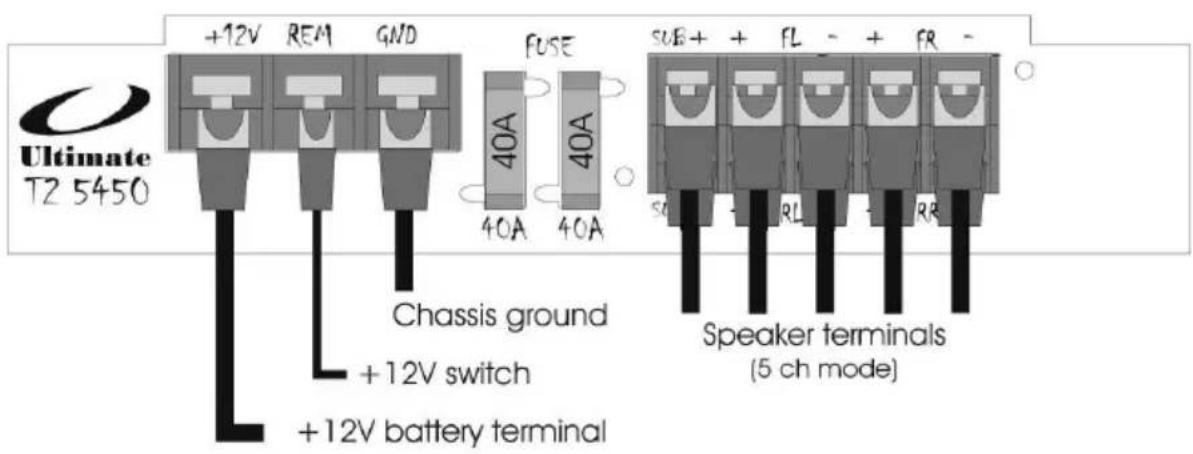
Using a minimum of 8 gauge wire, run a power cable directly to the positive terminal of your battery to the +12V terminal of your amp. A separate fuse must be located within 18 inches of the battery to protect the vehicle from a potential short. Total up the fuse ratings on your amplifiers to determine the fuse size required under the hood.
-
Your amplifier will turn on only when ignition is activated. This can be accomplished by connecting an 18 gauge wire to the 'trigger' output on your head unit. If you are using an OEM radio, this will not be available. You must locate a +12v switched circuit to achieve this.
-
The ground path is equally important to the positive feed of your amplifier. Find or create a bare metal spot on the vehicle's chassis. Using as short a wire as possible, connect to the 'GND' terminal using the same gauge wire as you did for power. The paint on the body must be removed to bare metal.
-
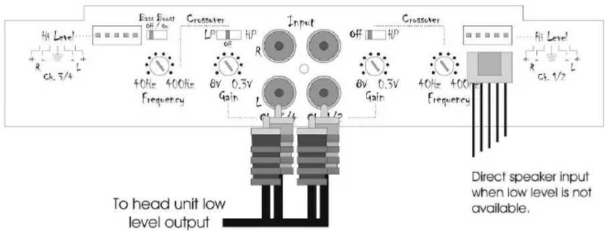
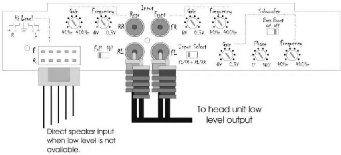
If you're using a low-level output signal from your head unit, ensure to use a high quality RCA cable to prevent unwanted noise. It is preferred to use the side opposite to the power wire to run the RCA. Failure to do so can introduce unwanted noise into the input signal which will be heard through your speakers.
-
If your head unit doesn't have RCA, then the hi-level input of the amp would be used. For this, it is ideal to tap in on the speakers closest to the amplifier location. Using regular 18 gauge speaker wire, take left and right (both positive and negative) signals. Connect directly to the 'hi-level' input on your amplifier. Proper gain settings are required to ensure undistorted sound.
-
You have now completed the basic installation portion of your new amplifier. Please continue to the "Amplifier Settings" section of this manual to properly configure your amp for maximum listening pleasure.
Amplifier Settings
The gain control (input sensitivity) on this amp is not a volume control. It is designed to provide proper matching of various source units to this amplifier, and provides a reference to how much signal will be necessary to reach maximum operating power. Correct settings will ensure safe operation for both your amplifier and speakers.
- Start by turning the gain level to the "8 volt" setting. This is the minimum level, far left.
- Next, turn up your head unit volume up to 75% of max volume. For example, if your digital volume control goes to "50", you would use the "40" level for this exercise.
- Last, slowly begin increasing the gain until distortion becomes audible, then turn the gain back a notch. You have now properly set your input sensitivity.
Crossover Control
Your amplifier has been designed with an onboard 18db/oct crossover, or filter management system. How you configure these settings will be dependent on the speakers you are connecting to the amp. The crossover circuit consists of two main settings: 1. Filter Type; 2. Frequency Adjustment.
The "filter type" is controlled by a "LPF, FULL, HPF" switch. The low-pass filter, LPF, will allow only low frequency information to pass on to the speakers. The opposite would be achieved using the HPF, high pass filter. When no filter is required, the FULL setting would be selected, allowing all frequencies to pass.
For proper operation of some speakers, it is necessary to select the crossover point to which they will play. The "frequency adjustment" setting allows you to accomplish this. In a LPF mode, only frequencies up to the crossover point will play, with a gentle roll-off beyond that point. In HPF mode, any frequency above that point will be heard, with those below being filtered away gradually.
Bass Boost
Sometimes, we want a little more kick to our system's bottom end. Your amplifier has been outfitted with an internal circuit to provide a boost at frequencies surrounding 45hz. A bass boost should be treated similar to a gain control. Proper adjustment of this setting will be required to ensure safe operation of your amplifier and speakers. When boosting the lower frequencies, turning the input sensitivity down would be required. Failure to do so may result in permanent damage.
Low Level Output
Rather than running a 2nd RCA for multiple amplifiers, the low level output will provide a full-range signal. Fading capability will not be possible in this arrangement.
| Specifications | T2-2250 | T2-2100 | T2-2450 |
| Continuous Power: | |||
| ·4 ohms | 55x2 | 100x2 | 55x4 |
| ·2 ohms | 80x2 | 190x2 | 80x4 |
| Maximum Power: | |||
| ·4 ohms | 140x2 | 240x2 | 140x4 |
| ·2 ohms | 320x2 | 360x2 | 200x4 |
| Bridged Power: | |||
| ·4 ohms | 160x1 | 400x1 | 160x2 |
| THD: | 0.05% | 0.05% | 0.04% |
| Signal to Noise Ratio | 91db | 101db | 90db |
| Frequency Response: | 10-110Khz | 10-110Khz | 10-110Khz |
| Speaker Impedance: | 2 ohms | 2 ohms | 2 ohms |
| Damping Factor: | 220@4 ohms | 240@4 ohms | 200@4 ohms |
| Input Sensitivity: | 300mV - 8V | 300mV - 8V | 300mV - 8V |
| Dimensions: | 9" x 11 3/4" x 2" | 9" x 18 1/2" x 2" | 9" x 17 5/8" x 2" |
| 23cm x 30cm x 5cm | 23cm x 47cm x 5cm | 23cm x 45cm x 5cm | |
| Fuse Rating: | 25A | 25A×2 | 20A×2 |
| Specifications | T2-5450 | T2-1200 | T2-1400 |
| Continuous Power: | |||
| ·4 ohms | 55x4 + 170x1 | 200x1 | 400x1 |
| ·2 ohms | 85x4 + 240x1 | 300x1 | 550x1 |
| Maximum Power: | |||
| ·4 ohms | 140x4 + 300x1 | 350x1 | 800x1 |
| ·2 ohms | 320x4 + 410x1 | 470x1 | 1100x1 |
| Bridged Power: | |||
| ·4 ohms | |||
| THD: | 0.05% | 0.12% | 0.04% |
| Signal to Noise Ratio | 96db | 97db | 97db |
| Frequency Response: | 10-110Khz | 10-200Khz | 10-200Khz |
| Speaker Impedance: | 2 ohms | 2 ohms | 2 ohms |
| Damping Factor: | 230@4 ohms | 180@4 ohms | 190@4 ohms |
| Input Sensitivity: | 300mV - 8V | 300mV - 8V | 300mV - 8V |
| Dimensions: | 9" x 205/8" x 2" | 9" x 141/2" x 2" | 9" x 181/2" x 2" |
| 23cm x 52cm x 5cm | 23cm x 37cm x 5cm | 23cm x 47cm x 5cm | |
| Fuse Rating: | 40A×2 | 30A | 30A×2 |
Introduction
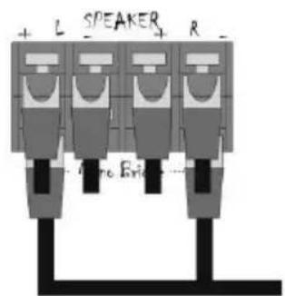
Speaker terminals
(3 ch mode)
Diagram
T2-5450

Speaker terminals
(3 ch mode)
Brand : Ultimate
Model : T22250
Category : Car radio