
BO219VDN - Cooker BOMPANI - Free user manual and instructions
Find the device manual for free BO219VDN BOMPANI in PDF.

| Product type | Built-in gas hob |
| Brand | Bompani |
| Model | BO219VDN |
| Number of burners | 4 |
| Burner types | 1 rapid (3000 W), 1 semi-rapid (1650 W), 1 auxiliary (1000 W), 1 triple crown (3500 W) |
| Ignition | Automatic with safety valve |
| Power supply | 230 V, 50 Hz |
| Gas supply | Natural gas (G20/G25) or butane/propane (G30/G31) |
| Dimensions (W x D x H) | 560 x 480 x 40 mm |
| Weight | Approximately 8 kg |
| Surface material | Enamelled glass |
| Maintenance | Clean with sponge and soapy water, removable burners |
| Safety | Safety valve against flame extinction, automatic gas shut-off |
| Installation | Built-in, class 3, requires hood or ventilation |
| Standards | EC Directives 2009/142, 2004/108, 2006/95, 2004/1935 |
| Spare parts | Nozzles, injectors, taps available from approved centre |
| Repairability | Repairs must be carried out by a qualified technician |
Frequently Asked Questions - BO219VDN BOMPANI
User questions about BO219VDN BOMPANI
0 question about this device. Answer the ones you know or ask your own.
Ask a new question about this device
Download the instructions for your Cooker in PDF format for free! Find your manual BO219VDN - BOMPANI and take your electronic device back in hand. On this page are published all the documents necessary for the use of your device. BO219VDN by BOMPANI.
USER MANUAL BO219VDN BOMPANI
| GB | INDEX | |||||
| General | notice | p | ||||
| Instructions for the user | p. 11 | |||||
| Using | the | burners | ||||
| Cleaning | p. | 11 | ||||
| Technical | characteristic | tables | p | |||
| Instructions | for | the | installer | |||
| Installation | p. | 13 | ||||
| Gas transformations and adjustments | p. 14 | |||||
| Maintenance | p. | |||||
| Description | of | the | cook-tops | |||
| Figures | p. | 34 | ||||
Dear Customer,
We thank you and congratulate you on granting us your preference, by purchasing one of our products.
We are sure that this new appliance, manufactured with quality materials, will meet your requirements in the best possible way.
The use of this new equipment is easy. However, we invite you to read this booklet carefully, before installing and using the appliance.
This booklet gives the right information on the installation, use and maintenance, as well as useful advice.
THE MANUFACTURER
GB GENERAL NOTICE

We invite you to read this instruction booklet carefully, before installing and using the equipment. It is very important that you keep this booklet together with the equipment for any future consultation.
If this equipment should be sold or transferred to another person, make sure that the new user receives the booklet, so that he can learn how to operate the appliance and read the corresponding notice.
This appliance complies with the following Directives:
EEC 2009/142/CE (Gas)
- The installation must be carried out by experienced and qualified personnel, in conformity with the regulations in force.
- This equipment has been designed to be used by adults.
- This appliance is not intended for use by person (including children) with reduced physical, sensory or mental capabilities, or lack of experience and knowledge, unless they have been given supervision or instruction concerning use of the appliance by a person responsible for their safety.
- Children should be supervised to ensure that they do not play with the appliance.
- Before powering the equipment, check that it is properly adjusted for the type of gas at disposal (see the "installation" paragraph).
- Before carrying out the maintenance or cleaning the equipment, cut power supply off and make it cool down.
- Make sure that air circulates around the gas equipment. Insufficient ventilation produces a lack of oxygen.
- In case of an intense or prolonged use of the equipment, it may be necessary to improve aeration, for example by opening a window or increasing the mechanical suction power, if it exists.
- The products of combustion must be discharged outside through a suction hood or an electric fan (see the "installation" paragraph).
- For any possible operation or modification, apply to an authorized Technical Assistance Centre and demand original spare parts.
The manufacturer refuses all responsibility for possible damages to things or people, resulting from a wrong installation or from an improper, incorrect or unreasonable use of this equipment.
This product complies with EU Directive 2002/96/EC.
The crossed-out dustbin symbol reported on the appliance indicates that the appliance must be disposed of separately from other domestic refuse at the end of its useful life. It must therefore be delivered to a waste recycling centre specifically for electric and electronic equipment or returned to the retailer at the moment of purchase of a new equivalent appliance.
The user is responsible for delivering the appliance to the appropriate collection centre at the end of its useful life, Failure to do so may result in a fine, as provided for by laws governing waste disposal.
Differential collection of waste products for eventual recycling, treatment and environmentally friendly disposal helps reduce possible negative effects on the environment and health, and also enables the materials making up the product to be recycled.
For more detailed information on the available refuse collection systems, refer to the local Municipal Solid Waste disposal centre or the shop where the product was purchased.
Producers and importers are responsible for fulfilling their obligations as regards recycling, treatment and environmentally friendly disposal by directly or indirectly participating in the collection system.
GB INSTRUCTIONS FOR THE USER

It is necessary that all the operations regarding the installation, adjustment and adaptation to the type of gas available are carried out by qualified personnel, in conformity with the regulations in force. The specific instructions are described in the booklet section intended for the installer.
USING THE BURNERS
The symbols silk-screen printed on the side of the knob indicate the correspondence between the knob and the burner.
Start-up without valves
Turn the corresponding knob anticlockwise up to the maximum position (large flame, fig.1) and press start-up button P (fig.1).
Automatic start-up with valves
Turn the corresponding knob anticlockwise up to the maximum position (large flame, fig. 1) and press the knob.
Once the burner has been started up, keep the knob pressed for about 10 seconds.
Using the burners
In order to obtain the maximum yield without waste of gas, it is important that the diameter of the pot is suitable for the burner potential (see the following table), so as to avoid that the flame goes out of the pot bottom (fig. 2).
Use the maximum capacity to quickly make the liquids reach the boiling temperature, and the reduced capacity to heat food or maintain boiling.
All of the operating positions must be chosen between the maximum and the minimum ones, never between the minimum position and the closing point.
The gas supply can be interrupted by turning the knob clockwise up to the closing position.
If there is no power supply, it is possible to light the burners with matches, setting the knob to the startup point (large flame, fig. 1).
| Burners Power W of pots | ||
| Auxiliary 1000 | 10 - 14 cm | |
| Semi-rapid 1650 | 16 - 18 cm | |
| Rapid 3000 | 20 - 22 cm | |
| Triple ring 3500 | 22 - 24 cm | |
Notice
- When the equipment is not working, always check that the knobs are in the closing position (see fig.1).
- If the flame should blow out accidentally, the safety valve will automatically stop the gas supply, after a few seconds. To restore operation, set the knob to the lighting point (large flame, fig.1).
- While cooking with fat or oil, pay the utmost attention as these substances can catch fire when overheated.
- Do not use sprays near the appliance in operation.
- Do not place unstable or deformed pots on the burner, so as to prevent them from overturning or overflowing.
- Make sure that pot handles are placed properly.
- When the burner is started up, check that the flame is regular and, before taking pots away, always lower the flame or put it out.
GB INSTRUCTIONS FOR THE USER
CLEANING
Before any operation, disconnect the appliance from the electric grid. Don't use a steam cleaner for the cleaning the hob.
It is advisable to clean the appliance when it is cold.
Glass platform and enamelled part
The glass platform and all of the enamelled parts must be washed with a sponge and soapy water or with a light detergent.
Do not use abrasive or corrosive products.
Do not leave substances, such as lemon or tomato
juice, salt water, vinegar, coffee and milk on the enamelled surfaces for a long time.
Burners and racks
These parts can be removed to make cleaning easier.
The burners must be washed with a sponge and soapy water or with a light detergent, wiped well and placed in their housing perfectly. Make sure that the flame-dividing ducts are not clogged.
Check that the feeler of the safety valve and the start-up electrode are always perfectly cleaned, so as to ensure an optimum operation.
Gas taps
The possible lubrication of the taps must be carried out by specialized personnel, exclusively.
In case of hardening or malfunctions in the gastaps, apply to the Customer Service.
GB TECHNICAL CHARACTERISTIC TABLES
| BURNERS | GAS g/h L/h | NORMAL PRESSURE 1/100 mm 1/100 | NOMINAL RATE | INJECTOR DIAMETER (%)* | TAPE BY-PASS DIAMETER | NOMINAL HEAT INPUT (W) | (EE gas burner) | |||
| N° DDESCRIPTION mba | mm MAK. MIN. | |||||||||
| 1 RAPID | G30 | 30 | 218 | 87 | 42 | 3000 | 950 | 53.8 | ||
| G31 | 37 | 214 | 87 | 42 | 3000 | 950 | ||||
| G20 | 20 | 274 | 129 | Reg. | 3000 | 950 | ||||
| 2 SEMI-RAPID | G30 | 30 | 120 | 65 | 31 | 1650 | 600 | 58 | ||
| G31 | 37 | 118 | 65 | 31 | 1650 | 600 | ||||
| G20 | 20 | 154 | 97 | Reg. | 1650 | 600 | ||||
| 3 | AUXILIARY | G30 | 30 | 73 | 50 | 27 | 1000 | 450 | / | |
| G31 | 37 | 72 | 50 | 27 | 1000 | 450 | ||||
| G20 | 20 | 95 | 77 | Reg. | 1000 | 450 | ||||
| 4 | ULTRA-RAPID | G30 | 30 | 255 | 94 | 60 | 3500 | 2100 | 56.6 | |
| G31 | 37 | 250 | 94 | 60 | 3500 | 2100 | ||||
| G20 | 20 | 334 | 141 | Reg. | 3500 | 2100 | ||||
Short title or reference methods of measurement and calculation used to establish compliance with the above requirements.
The performance of each individual burner is calculated according to EN 30-2-1 + A1: 2003 + A2: 2005.
The total return of the cooking surface is calculated according to EU Regulation 66/2014 Par. 2.2.
The efficiency is calculated only for the burners with a nominal capacity exceeding 1.16 kW (EN 30-2-1 + A1: 2003 + A2 : 2005; Par 4.1)
Information relevant to the customer to minimize energy consumption during use.
Saving tips:
common use pots with flat base, Use pots with the correct format, Use pots with a lid, minimize the amount of fat or liquid, when you start a hot liquid to reduce the setting.
GB INSTRUCTIONS FOR THE USER

IMPORTANT NOTICE
THE OPERATIONS INDICATED BELOW MUST BE FOLLOWED BY QUALIFIED PERSONNEL EXCLUSIVELY, IN CONFORMITY WITH THE REGULATIONS IN FORCE.
THE MANUFACTURING FIRM REFUSES ALL RESPONSIBILITY FOR DAMAGES TO PEOPLE, ANIMALS OR THINGS, RESULTING FROM THE FAILURE TO COMPLY WITH SUCH PROVISIONS.
INSTALLATION
Installing the top
The appliance is designed to be embedded into heat-resistant pieces of furniture.
The walls of the pieces of furniture must resist a temperature of 65^ besides the room one.
The equipment must not be installed near inflammable materials, such as curtains, cloths, etc.
Make a hole in the top of the piece of furniture with the dimensions indicated in fig.3, at a distance of at least 50~mm from the appliance border to the adjacent walls.
Any possible wall unit over the cook-top must be placed at a distance of at least 760~mm from the top.
It is advisable to isolate the appliance from the piece of furniture below with a separator, leaving a depression space of at least 10mm (fig.4).
Fastening the top
Every cook-top is equipped with a special washer having an adhesive side.
- Remove the racks and burners from the top
- Turn the appliance upside down and lay the adhesive washer S along the external border of the glass (fig.5).
- Introduce and place the cook-top in the hole made in the piece of furniture, then block it with the V screws of the fastening hooks G (fig.6).
Installation room
This appliance is not provided with a device for exhausting the products of combustion. Therefore, it is necessary to discharge these smokes outside.
The room where this appliance is installed must have a natural air inflow, so as to ensure a regular gas combustion and room ventilation: the necessary air volume must not be lower than 20m^3
Air must come from permanent openings made on the room walls that communicate with the outside. The section of these openings shall correspond to at least 200~cm^2
Gas connection
Make sure that the appliance is adjusted for the gas type available (see the label under the appliance). Follow the instructions indicated in the chapter "gas transformations and adjustments" for the possible adaptation to different gases.
The appliance must be connected to the gas system by means of still metal pipes or flexible steel pipes having continuous walls, in compliance with the regulations in force.
Gas enters the appliance through a cylindrical threaded male gas union (1 / 2^ )
The connection must not stress the gas ramp.
Once the installation is over, check the connection seal with a soapy solution.
GB INSTRUCTIONS FOR THE INSTALLER
Electric connection
The connection to the electric grid must be carried out by qualified personnel and in conformity with the regulations in force.
The voltage of the electric system must correspond to the value indicated in the label under the appliance. Make sure that the electric system is provided with an effective ground connection in compliance with the regulations and provisions of the law. Grounding is compulsory.
GAS TRANSFORMATIONS AND ADJUSTMENTS
Replacing the nozzles
If the equipment is adjusted for a type of gas that is different from the one available, it is necessary to replace the burner nozzles.
The choice of the nozzles to replace must be made according to the table of the "technical characteristics".
Act as follows:
- Remove the racks and burners.
- by means of a straight spanner L, unscrew the nozzle U (fig.7) and substitute it with the corresponding one.
- tighten the nozzle strongly.
Adjusting the burners
The lowest flame point must always be properly adjusted and the flame must remain on even if there is an abrupt shift from the maximum to the minimum position.
If this is not so, it is necessary to adjust the lowest flame point as follows:
- start the burner up
- turn the tap up to the minimum position (small flame)
- remove the knob from the tap rod
- introduce a flat-tip screwdriver C in the hole F of the tap (fig.8) and turn the by-pass screw up to a proper adjustment of the lowest flame point.
As regards propane gas burners, the by-pass screw must be tightened completely.
MAINTENANCE
Replacing the power supply cable
If the power supply cable should be replaced, it is necessary to use a cable with a section of 3 × 0.75 ~m^2 , type H05VV-F or H05RR-F, complying with the regulations in force.
The connection to the terminal board must be effected as shown in fig. 9:
brown cable L (phase)
blue cable N (neutral)
green-yellow cable

(ground)
HIXKEONHCAHHbIEIENCTBnIIOJIKHbIBbITbIIPOUN3BEIeHBiBCOOTBETCTBNNC
JEHCTBYIOIIMNHOPMAMN TOJIBKO KBAJIINPHIIPOBAHHBIMN PABOTHIKAMN.
ΦHPMA IIPINBBOJNTEJIb OTKJOHRET JIOEBYIO OTBETCTBEHHOCTb 3A YIIEPE,IIPINHNHEHHBI
JIOJIM, KHBOTbIM HII INIPEIMETAM, IPOHCXOJIHIN H3-3A HECOBIOJEHHA TAKHX IIPABNI.
VCTAHABJINBAHNE
MoHTaX IIHTbI
YcTpoHCTBO cKoHcTpynpOBAHHo IJIa BcTpoKNB TEJIIOyTOHBYIO Me6JIb.
CTeHK Me6eJH IOJXHbI 6bITb CToIKK K TeMIIepaType 65^ IeJIbChn NOMHMO ycToHBOcTH TEmIIepaType OKpyKaHOICn CpeIbI, B COOTBcTcTBHN C CBPOINCKHMn HOpMaMH EH 60 336-1-2-6.
TO yctpoCTBO TnHa "Y" TaKKe, MoKcT 6bITb yCTaHOBJIeHO TOJbKO c OJHO BOKOBIcTeHO CnpBa HIN CJIeBA OT paOoey IOBepxHocTH.
He IOnyckaTb yCTaHaBJIHBAHHe yCTpoHCTBa pIOM c JcIKKOBOCIIJAMCHRAIOHMHCs MaTePhaJIaMn TaKHMN KaK IIITOPb, KaHBA H T.I.
HcnoJb3OBaTb OTBepCTHe B NOBepXHOCTn Me6eHN COOTBeTCT. pa3Mepam yKa3aHHbIM Ha pnc. 3 co6JIIOaI paCCTOAHHe MHHHMyM 50MM ot Kpa YcTPOINCTBa Jo 6JIH3JIeKaIIHXCTeh.
IIOJka, KOtopar MoKet HaxoHTbcra Ha paOoye IOBepxHocTbIO DoJXHa 6bITb Ha pacCToHHn He MeHee 760 MM OT IOBepxHocTH.
Cobetyetcna H3oJnHPOBaTb ycIpoNCTBO,OT HnKecToaIeMbeJIH, IpeRopOdkoI,ocTabHB pacctoHHyey6JIeHHa, KaMmHHmym10 MM (pnc.4).
JaHHOyeyctpoiCTBOYABJIEETcYcTPOIeTBOM3Klacca.
3akpeIIJIeHHe IIJITbI
KaJJaIJIHTa OCHAeHa CneHnJIbHOI PpOKJaIKoI c KJIeIKoI CTOpHOI.
- Chrtb c IIINTb peHETKN I RopeJIKN.
- IpepeBepHyTb yctpoIcTBo H pa3JIOxKHTb BIOJIb BHeIIHcCTeKJIaHHOHN KpOMKn KJIeIKyU IIpOKJaIKy S (pHc. 5).
-BCTaBHTb H IIO3HUNOHNPOBaTb IIJNTy B OTBepCTHN yCTaHOBJeHHOM B Me6eJIH N 3aKpeIHTb IIJNTy BNHTaMH KPHOCHOBΦHKCnPOBaHHa V (pHC.6).
IomeeHne IyctaHOBKn
TO yCTpoIcTBO He cHa6KeHO MExaHn3MOMBbI c6pOca OTxODOB CROPaHHa, TaKHM O6pa3OM Heo6XoHMO Bbl6paCbBaTb 3TN IblMbI HApyKy HcIOJIb3yJ YbIMoyIOBHTeJIb HIN 3JIeKTPOBEHTHJTOp, KOTOpbI 6yIcT BKJIHOATbcra KaKdIpa3 IIpn HcIOJIb3OBAHHY yCTpoIcTba.
IomeeHHe, B KOTOpOM 6yDet yctaHOBJeHO yCTPOINCTBO, DOLJKHNO HMeTb CNOHTAHHHI INPHTOK BO3dyxa IJIpeRyJInpOBaHHc CROPAA Ra3a IJIBAEHTHJIaII; HEo6XODHMoe KOJ-BO BO3dyxa He IOJIKHO 6bITb MCHCC 20M.
IpiHtOK BO3dyxa DOJIKeH IPOHCXoHNb H3OTBepCTHn IOCTOARHHo HAXOJIMHXcB CTeHax NOMEeHnB bIXoJIMHX HApKy.
BeHTHJIaIIH MoKeT TaKKe, IPOHCxoIHTb H3cMeJxHO IOMeIeHHB, B 3TOM cIyuae IIpHJePkHBaTbC8 TOrO, YTO IIpeIINcaHO DeIcTBYIOUHMn HopMaMH. OTBepCTNIA JOJIKHbIMTeB MHHMaJIbHyIO cekIIIO 200 cm².
PiokJIOueHne Ra3a
YIOCTOBEPHTbC,HTO yCTPOIcTBO IIpeIpaIIOJOKeHO KTHIy Ra3a HMeIOIeMycB HAJIINH, IOCMOITpeTB HaOTHKETKy IOJ yCTPOIcTBOM HIN HA IocJIeIHei CTpaHHue 3TOI KHIN
IeCTBOBaTb IIO HHCtpyKIIHM IIpHBeJeHHbIM B Iaparpafe "H3MeHeHne Ra3a H peryJInHpOBaHne" JIA BO3MOKHOIPO IIpcHcIOcaJIINBaHHK IpyTM Ra3aM.
YcTpoIcTBoIOJIKHO6bITbINHHeHO Kra3OBOI cHCTeMe HcIOJIb3yJXcTKe MeTaJIINHeckne Tpy6bI HJIN HCIOJIb3yra Rn6KNe CtaJIeBbIe Tpy6b COOTBeTcTBYIOIIHeJeICTBYIOIH M HopMaM.
CoeHHeHHe ra3OBOro BXOJa ycTpoIcTba Hape3aHo pe3b60nra3OBbI uHHInHIpNueckn CTepKeHb.
CoeHHeHHe He OJxHO BbI3bBaTb Harpy3Ky Ha ra3OByIO paMIIy.
B KOHue yctaHaBJIHbAHn IpoKoHTpOJIHpOBaTb IpoUHOCTb coeHHHeHH nIph IOMOII MblbHoropactbopa.
RUS INHCTPYKIIINДЛЯ YCTAHOBIUNKA
3JIeKtpnueckoe coeHHenne
IIOcoeHNHeHne KJleKtpn. cetn IOJXHO 6bITb IPOH3BeJeHO KBaJIHΦHnPObAHbIMn pa6OTHKAMN H B COOTBeTcTBHH C JeHCTBYIOHMn HopMaMH.
HaipjkeHne 3JIeKtpnueckoI cetn IOJXHO COOTBeTcTBOBaTb HaipjKeHHIO yKa3aHHOMy Ha 3THKETKe IOD yCTPOHCTBOM.
IpoBepntb, Yo6b 9JekTpuecka cetb 6bla chaokeha ofoekTHBbIM 3a3emJIeHHe BCOOTBeCTBHN C HopMaHn IIpeIIINcaHHMa 3aKoHa. HaHnHe 3a3emJIeHHN 06aTeJIbHo.
EcJn yctpoNCTBO He HmeeT IITeIcEJIbHOB BNJKn IIpHcoeINHHtB K Ka6JIIO IHTaHHa CtaHJaPTHyO BNIky.
Mojno npoH3BecTH NOcOeHNHeHne IprMo K OJIeKtpnueckoN cETN HcIOJIb3yMa MHOrOIOJIocHbI BblKIIHOuataJIb, HMeIoUH paCCToHHe MeJdy KOHTaTAM, KaK MHHmym 3MM.
ΓA3AN3H3M
PEΓΥΙΝΟΒΑΝΗΕ
3aMeHa coIeJI
EcIn y cTpoNCTBO npeIpaacnoJIOKeHo K TnIy ra3a OTJIHuaOIIeMycs OT HMeIOIeROc, TO Heo6XoIHMO 3aMeHHTb COIIa RopeJIOK.
Bb6op coJIJI 3aMeHb IIOJIKeH 6bITb cJeIah IO Ta6JIHue "TexHHueckHe xapaKTePHCTHKN".
IeHCTBOBaTb B CJIeDyIOUHeI IOcJIeIOBaTeJIbHOCTn:
- CHTb peIeTKN H ropeJIKN.
-C IIOOMOIOIINMORO KJIOUa L OTBHHHTbCOIIIO U (pHc.7) H 3aMeHHb eTOpyHM COOTBEtCTBYIOHNM.
-БлOKнроватьэHeprHuHcOПJO.
Pery.lnpobahne ropeJIOK
PeryHpoBaHne MHHMyma IOJIXHO 6bITbBcerIa KoppeKTHO H OTOHB IOJXKeH OCTaBAtbcra 3aKkEHHbIM JaKe IocJIe pe3KOrO IepExoJa OT I03HmMaKcHMyM IO IIO3HmHHMmHym.
EcJH 3TOrO He cJyuaetc, Heo6xOJHMO OtperyJnpoBaTB MHHMym B CJIeIyIOUeH IOcJIeIOBATEJIbHOCTN:
- 3aKeueb ropejKy;
-Поверншт руку крапа по пиони МHHМу(MaJIeHbKnOroHB); - CnTb pyKy KpaHa co cTeprKH;
- BctaBHTb OTBepTKy C B OTBepCTHe KpaHa F (pnc. 8) H IOBOPaHbATb 6aIIacHbI BHHT IO KoppcKTHOrO OTpeRyJINHOBaHHMHHMMyMa.
JrropeIOK cyHKUHOHpyUOuHX cra3OM G 30 6aIacbBnHT IOJIKeH 6bITb 3aBHHeH IOJIHOCTbO.
VXOД
Cma3bIbaHHe KpaHOB
B cIyac, cIIN KpaH IIpoBJIeT JKcCTKocTB pa6Ote, Heo6xoJIMO pa3o6paTb erH cMa3aTb. JeIcTBHH IJIra IIPOBeJeHH, cJIeYIOIIHe:
-OTBHHHTb IBA BHHTa, KOtOpbIe 6IOKHPyIOT ΦJIaHeI ROJIOBKn KpaHa
-ПОДНЯТБ KOHyc perуЛнрOBaHHra3a H aKKypaTHO IIOHCTNHTb cRO 6CH3HHOM HJIN pactBOPHpCJIcM
-Cma3aTb eTo He60JIbHMM KOJInueCTBOM rYcTOI CMA3KN IJIY BbICOKHX TeMIIePaTyPO6paIIa BHHMaHHe Ha To, YTO6bI He 3acOpHTb OTBepCTHn IpoxOJa ra3a
-Co6paTb TIIaTeJIbHO Bce DeTaJIH.
3aMeHa Ka6eJI HHTaHH
B cIyac 3aMcHb Ka6eJII HHTaHH JIOJIKeH6bITb yIOTpe6JIeH Ka6eJIb IIO HopMaM, TIIHa KO5VV-F HIIHO5RR-F HAcbIeHHem 3r 0,75 MM.I. IIOcOeINHeHne K EHMHIOPO6Ke IOJIJKHO 6bITb CJeJaHo, KaK IOKa3aHO Ha pnc.9:
npo6oD L Kopuuee8bui (xo0)
npo6oN cunui (neimpaibhbu)
npo60d 3e1eNo-ooimb(3a3eMienue)
FIGURE FIGURES FIGURES ABBILDUNGEN PNCYHKN
(EE_gas hob = 56.6%) (EE
gas hob = 56.6 %)
(EE_gas hob = 56.6%)
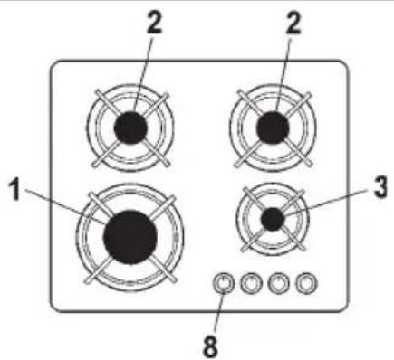
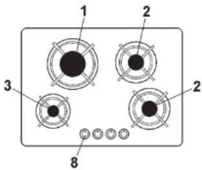
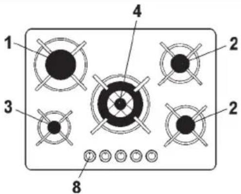
1 Rapid burner 3000 W
2 Semi-rapid burner 1650 W
3 Auxiliary burner 1000 W
4 Triple ring burner 3500 W
8 Control knob for burner