
OpenTherm 123100 - Thermostat DE DIETRICH - Free user manual and instructions
Find the device manual for free OpenTherm 123100 DE DIETRICH in PDF.
| Product type | OpenTherm and RF modulating room thermostat |
| Dimensions (L x W x H) | 96 x 144 x 34 mm (with buttons); 96 x 144 x 25 mm (without buttons) |
| Power supply | OpenTherm via boiler (pilot wire); RF version: 3 AA batteries or 5 VDC adapter |
| Display | Blue backlight, pictograms, text area, temperature and time |
| Ambient temperature range | Measurement: -5 °C to 65 °C; Setting: 5 °C to 35 °C |
| Temperature accuracy | Max deviation of 0.3 °C at 20 °C |
| Clock programs | 2 programs with up to 6 switches per day |
| Holiday programs | 16 programs with start and end dates |
| Usage modes | Basic, Normal, Extended (user mode) |
| Regulation strategies | Room thermostat, variable setpoint, 4 combinations |
| Wired communication | OpenTherm V3.0 SmartPower (non-polarized) |
| Wireless communication (RF) | Secure bidirectional, typical indoor range of 30 m |
| Batteries | 3 x AA (not supplied), lifespan varies by brand |
| Operating conditions | 0 °C to 60 °C (without batteries); 0 °C to 55 °C (with batteries) |
| Protection rating | IP20 (wall-mounted), IPx4 (built-in) |
| Digital input | Potential-free contact (external switch) |
| Additional options | Outdoor sensor (optional), RF room sensor (optional) |
| Special functions | Chimney mode, anti-legionella, DHW standby, preheating |
| Installation | Wall-mounted with screws and wall plugs, or flush-mounting box (ref. S100994) |
| Compliance | EMC 2004/108/EC, RoHS, OpenTherm V3.0 SmartPower, ETSI 300-220 (RF) |
Frequently Asked Questions - OpenTherm 123100 DE DIETRICH
User questions about OpenTherm 123100 DE DIETRICH
0 question about this device. Answer the ones you know or ask your own.
Ask a new question about this device
Download the instructions for your Thermostat in PDF format for free! Find your manual OpenTherm 123100 - DE DIETRICH and take your electronic device back in hand. On this page are published all the documents necessary for the use of your device. OpenTherm 123100 by DE DIETRICH.
USER MANUAL OpenTherm 123100 DE DIETRICH
Inhoudsopgave
natural_image
Illustration of a hand pressing a button on a wall, showing rotational motion (no text or symbols)NL
3. Installatie
natural_image
Isometric technical diagram of a mechanical assembly with no visible text or symbolsE-code: Ketelstoring
3.1 Location of the thermostat..... 48
3.2 Installation and connection. ..... 50
3.3 Location of the outside sensor..... 51
3.4 Room sensor (for thermostat RF only)
52
- Prior to first use 53
4.1 Setting language, time and date. 53
4.2 Default setting.... 53
- Setting 54
5.1 Three user modes 54
5.2 Creating or changing a clock program 55
5.3Settingcontinuous temperatures 59
5.4 Group control.... 59
5.5 Setting the control strategy ..... 60
5.6 Setting a holiday program ..... 63
5.7 Other settings 64
- Using the thermostat.... 65
6.1 Selecting a program 65
6.2 Temporarily changing the temperature 65
6.3 Fireplace mode.... 66
6.4 Information.... 67
- Messages 67
7.1 Fault messages 68
7.2 Service message.... 73
- Problems and solutions.... 74
- Technical specifications .... 79
Appendix: clock program template ..... 82
1. Introduction
The modulating timer thermostat is an OpenTherm timer thermostat with many enhanced functions.
The thermostat is supplied in two versions:
• Thermostat OpenTherm
• Thermostat RF (wireless), with the base station RF transmitter
This manual covers both versions (OpenTherm and RF). Where information only pertains to one of the two versions then this is clearly stated.
A full description of the thermostat can be found in the Installation and Service manual.
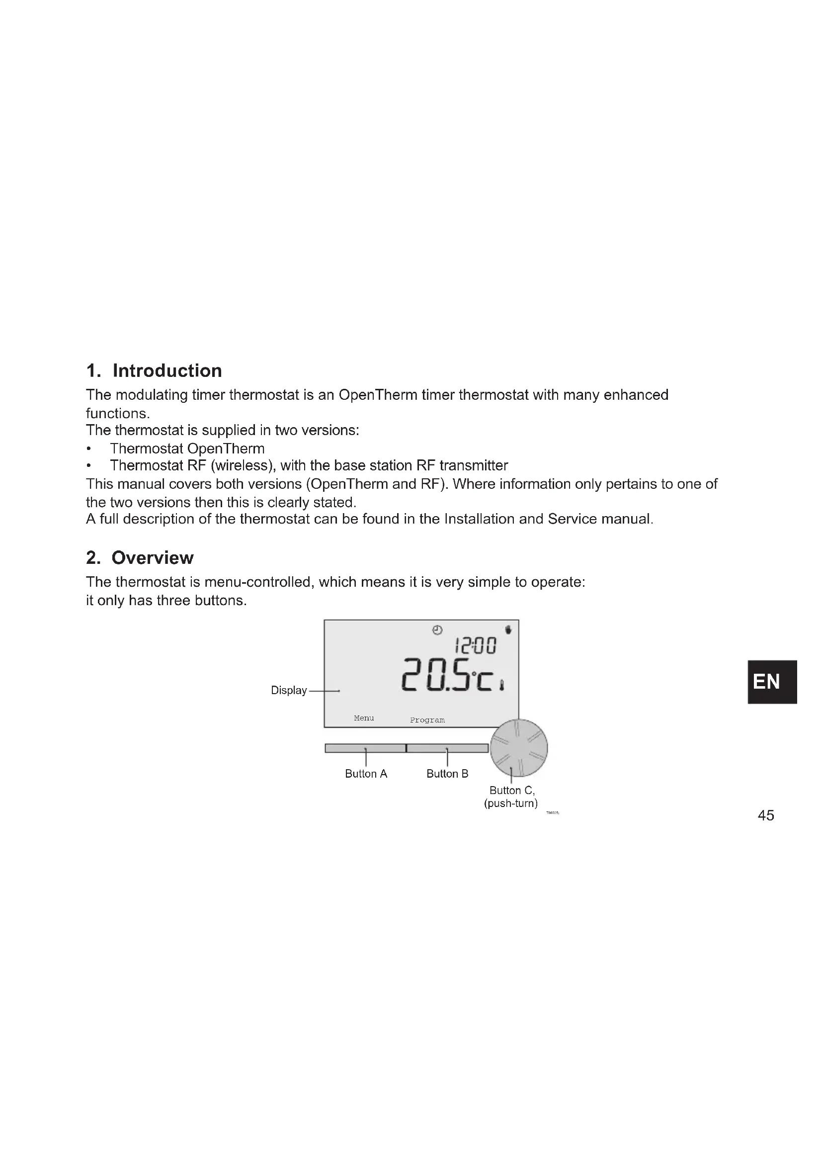
2. Overview
The thermostat is menu-controlled, which means it is very simple to operate: it only has three buttons.
2.1 Display
Most important pictograms Pictograms not shown
Clock program active
Continuous day temperature
( Continuous night temperature
* Frost protection
Summer mode
Manual setting
☐ Holiday program Warning symbols
※ DHW standby function switched off
Current room temperature
Room temperature set
☐ Thermostat requesting heat
Central heating boiler on for hot water
Central heating boiler on for central heating
Group 1 selected
Group 2 selected
4 Production of electricity
Water pressure in central heating boiler too low
⚠️ General warning symbol
f Central heating boiler requires servicing
Battery in thermostat almost empty
(i) No wireless connection
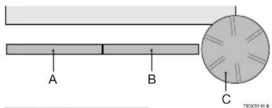
2.2 Buttons
The function of button A and button B depends on the task you are carrying out. The function is shown in the display, immediately above the buttons.
Button C is a push-turn button. You press it to confirm choices, such as menu selections. By turning it you can perform various tasks such as scrolling through menus or changing values such as the temperature, time, date and language.
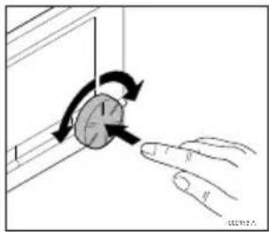
natural_image
Illustration of a hand pressing a button on a panel, showing rotational motion (no text or symbols)EN
3. Installation
3.1 Location of the thermostat
The thermostat is set to room control by default, which means that the inside temperature is used to control the central heating. That is why it is best to locate the thermostat on an internal wall in the room in which you spend the most time, such as the living room.
Do not locate the thermostat too close to heat sources (fireplace, radiator, lamp, candles, direct sunlight etc.), or in places where it may be draughty.
Thermostat RF
The following also apply for the thermostat RF:
- Position the thermostat at least 1 metre from equipment with electromagnetic emissions such as washing machines, Tumble driers, wireless telephones, TVs, computers, microwave ovens, etc.
- Position the thermostat so that it has good reception. Take account of the fact that objects containing metal will affect the reception. These include steel-reinforced concrete, mirrors and windows with a metal coating, insulating films etc.

Thermostat RF wireless range
The range of the thermostat RF in buildings is generally 30 metres.
Note!
This value is purely an indication. The actual range of the RF signal depends strongly on the local environment. Remember that the number of walls and ceilings (metal or otherwise) can have a (considerable) impact on reception. Other objects that contain metal may also impact reception. These include mirrors and windows with a metal coating, insulating films etc.
i The signal strength can be viewed via Menu > Information.
3.2 Installation and connection
The following must be done before you install and connect the thermostat:
- Adjust the boiler so that it can be connected to an OpenTherm thermostat.
• Turn off the boiler.
Consult the boiler documentation for this process.
Do this as follows:
-
Open the housing by pulling the front and the base plate apart.
-
Attach the base plate of the thermostat to the wall using the screws and plugs supplied. Ensure that the boiler's connecting wires are protruding through the hole in the base plate.
-
Connect the thermostat to the boiler OpenTherm connection and the thermostat OT connection. OpenTherm is polarity insensitive; you may therefore swap the wires.
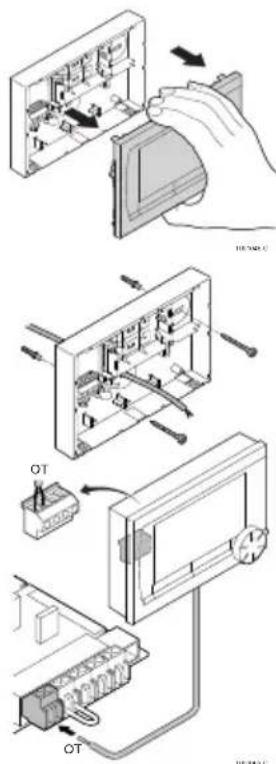

- Place three AA batteries in the thermostat if required.
These are not provided. The batteries ensure that the clock keeps running when the boiler is switched off.
The batteries also power the backlight for the thermostat for boilers that do not have OpenTherm Smart Power. If you have a boiler with Smart Power, then the backlight for the thermostat also works without batteries.
(Thermostat RF only) Place 3 AA batteries in the thermostat.
These are required to operate the thermostat RF.
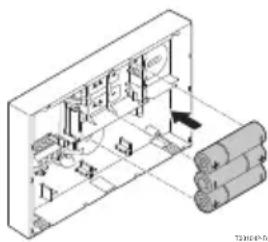
The programs that are set are saved if the boiler or the thermostat is switched off (even if there are no batteries).
The thermostat RF automatically starts communicating with the base station.
3.3 Location of the outside sensor
An outside temperature sensor is not supplied as standard with the thermostat.
You only require this sensor if you want weather-compensated control of the inside temperature.
The following guidelines apply with regard to choosing a location for an outside temperature sensor:
• Install the outside sensor on the north or north-west side of the home, away from direct sunlight.
• The sensor must be positioned at least 2.5 metres above ground level.
- Do not install the outside sensor near windows, doors, ventilation grills, extractors, etc.
Consult the documentation for your boiler for information on connecting an outside temperature sensor.
3.4 Room sensor (for thermostat RF only)
An RF room sensor is available for the thermostat RF as an option. This sensor replaces the internal thermostat sensor.
EN
4. Prior to first use
4.1 Setting language, time and date
The menu for selecting the language (international version) or setting the time (Dutch version) appears when you connect the thermostat.
- Select the desired language if applicable by turning button C and then push button C to confirm.
- Follow the instructions on the display to select the time, year, month and day.
The thermostat is now ready for use. After installation, the default program is activated (see paragraph 4.2). The temperature is now controlled by this clock program.
The thermostat automatically switches between summer time and winter time settings.
4.2 Default setting
Room control
The thermostat is set to room control by default. This means that the flow temperature of the central heating water is controlled by the temperature in the room where the thermostat is installed. Weather-compensated boiler control is also possible (with outside sensor); in other words based on the outside temperature. The thermostat has a programmed heating curve which determines the water flow temperature together with the outside temperature. The heating curve must be chosen so that the least favourable room can be efficiently heated even when the outside temperature is very low.
See paragraph 5.5 for further information about weather-compensated control.
Clock program
The default clock program sets the temperature each day as follows:
• 06:00 – 19:00: 20°C
• 19:00 – 23:00: 21°C
- 23:00 - 06:00: 15^ C +
You can of course adapt the clock programs to your own requirements. See Chapter 5.
5. Setting
5.1 Three usage modes
The thermostat has three usage modes:
• Basic: no clock programs are used in this mode.
You can only set the temperature on the thermostat manually.
• Normal: this is the standard mode. Most options are available, such as the clock program.
- Advanced: this mode lets you use two standard clock programs (A and B), change more settings and request more detailed information.
You can change the usage mode via the menu: Menu > Settings > Users > User mode.
This manual deals with most functions relating to the 'Normal' mode. This is the default mode after initial start-up.
5.2 Creating or changing a clock program
A clock program automatically controls the temperature for a day, and can be set for each individual day. You can adjust the default clock program or enter a completely new program.
The thermostat starts pre-heating prior to the set time by default, so that the room has reached the desired temperature at the correct time.
Making an overview
It is useful to draw up your own overview with switch times: what temperature does it need to be and when in your home? This of course depends on who is at home when, what time you get up etc. You can set up to six switch times per day.
An example of an overview is shown below:
| Time | D. TU. WE. TH. FR. SA. SU. | ||||||||
| 7:00 20°C | C | 20°C | 20°C | 20°C | 20°C | ||||
| 9:00 15°C | C | 15°C | 15°C | 15°C | 20°C | 20°C | |||
| 11:00 | |||||||||
| 13:00 | |||||||||
| 15:00 15°C | |||||||||
| 17:00 | |||||||||
| 19:00 21°C | C | 21°C | 21°C | 21°C | 21°C | ||||
| 21:00 21°C | |||||||||
| 23:00 15°C | C | 15°C | 15°C | 15°C | 15°C | ||||
| 0:00 15°C | C | 15°C | |||||||
EN
There is an overview template at the back of this manual that you can use for your own clock program.
Creating a new clock program
- Select Menu > Program > Clock prog. > New time.
- Select an initial program if appropriate (Daytime home, Midweek home or Weekend home).
You can now create your own clock program based on this program.
Press button C to confirm. - Go to the day for which you want to set the clock program.
Press button C to confirm. - Go to the time you want to set. Press button C to confirm.
① You can use the button to remove the selected switch time.
-
Use button C to set the time and the corresponding desired temperature.
-
Once you have set all switch times for a particular day, you can copy the settings for that day to other days:
- Go to the day.
- Press Copy.
- Select the day(s) to which you want to copy the settings using button C and press Save.
-
Go to the day. Then press button C.
-
Go to step 3 to set the next day, or press Back to close this menu.
Changing an existing clock program
- Select Menu > Program > Clock prog. > Change.
- Go to the day for which you want to change the clock program. Press button C to confirm.
- Go to the time you want to change. Press button C to confirm.

You can use the button to remove the selected switch time.
- Use button C to set the time and the corresponding desired temperature.
- Once you have set all switch times for a particular day, you can copy the settings for that day to other days:
- Go to the day.
- Press Copy.
- Select the day(s) to which you want to copy the settings using button C and press Save.
- Go to the day. Then press button C.
- Go to step 2 to set the next day, or press Back to close this menu.
Restoring the default settings
Select Menu > Program > Clock prog. > Factory settings to restore the settings for the default clock program.
5.3 Setting continuous temperatures
Instead of the clock program, you can also set the room temperature continuously to a particular value. You can set three different continuous temperatures via Menu > Program:
- Day temp.: room temperature during the day, corresponding to the “Continuous day” program.
- Night temp.: room temperature at night, corresponding to the “Continuous night” program.
- Frost temp.: room temperature to protect the room where the controller is installed from freezing. This setting comes under the "Frost protected" program.
i The programs mentioned are explained in paragraph 6.1.
5.4 Group control
With the aid of the c-Mix, the thermostat can control two groups; both groups can be assigned their own program and control strategy. This is done via: Menu>Settings>System>Central Heating system>Groups "no groups" is the default setting.
The option "1&2 separately" can be used to assign each group its own program. The icon will appear in the standard screen. You can then press the rotary knob/pushbutton to switch between control of group 1 and group 2. If "2 follows 1" is selected, both groups are assigned their own strategy, but group 2 will follow the program for group 1.
5.5 Setting the control strategy
The thermostat lets you use the room control and/or weather-compensated control strategies in various ways.
You can select a control strategy via Menu > Settings > System > Control settings.
When implementing these changes, the user level must be set to "Extended mode". (See para. 5.1)
Specific settings for weather-compensated control
If you have opted for a weather-compensated control strategy, a number of extra settings are available via Menu > Settings > System > OTC settings.
Heating curve:
- Base outside: outside temperature base point
- Base flowtemp: flow temperature base point
• Climate outside: outside temperature climate point
• Climate flowtemp: flow temperature climate point - Curvature: degree of curvature of the heating curve, depending on your central heating system. Select the relevant type of heaters: underfloor heating, radiators or convectors.
This will provide more comfort early and late in the year.
The heating curve is based on an outside temperature of 20^ C. When the desired room temperature is increased, the heating curve shifts upwards. The degree of increase is determined using the “RT effect” function.
• RT effect: factor influencing the shift in the heating curve
- Heat limit day: outside temperature above which the central heating is switched off during the day. The day temperature limit is relevant when the desired room temperature is higher than the night temperature that has been set via Menu > Program > Night temp.
- Night temperature limit: outside temperature above which the central heating is switched off during the night. The night temperature limit is relevant when the desired room temperature is the same as or lower than the night temperature that has been set via Menu > Program > Night temp.
Heating curve – an example
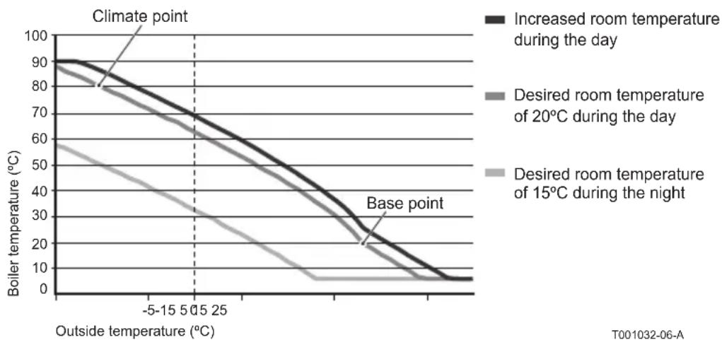
line
| Outside temperature (°C) | Increased room temperature during the day | Desired room temperature of 20°C during the day | Desired room temperature of 15°C during the night | | ------------------------ | ----------------------------------------- | ------------------------------------------------- | ------------------------------------------------- | | -5 | 90 | 85 | 60 | | 0 | 80 | 75 | 45 | | 5 | 70 | 65 | 35 | | 15 | 60 | 55 | 25 | | 25 | 50 | 45 | 15 | | >25 | ~20 | ~15 | ~5 |① See also see day/night temperature limit 12.4
The settings for the heating curve are highly dependent on the design of the central heating system and the home. This means that no clear advice can be given on this matter. The heating curve can be optimised during use. The heating curve also shifts upwards or downwards when the temperature is increased or decreased.
5.6 Setting a holiday program
It can be useful to set a holiday program if you are away from home for some time.
This ensures a constant temperature in your home for the period you set.
You set the temperature yourself.
A holiday program automatically takes effect at 0.00 hours on the start date and ends at 0.00 on the end date.
The symbol □ appears in the display.
This program is switched off and removed once the period set has ended.
You can set a maximum of 16 holiday programs.
You do this via Menu > Program > Holiday prog.:
- Select View to look at the holiday programs set.
- Select Change to change or remove programs.
- Select Enter to add a new program.
- Select Desired temp. to set the constant temperature.
5.7 Other settings
You can change a number of settings via the Settings menu. These are summarised here; a more detailed explanation can be found in the Installation and Service manual.
• Language and display settings.
- Calibration: you can calibrate the sensor by positioning an accurate thermometer next to the thermostat.
• Comfort correction: the thermostat takes into account the perceived temperature.
- Frost protection: if an external sensor is connected, the outside temperature will be used to switch on the frost protection automatically. If the outside temperature falls below the set value, the pump will continue to run and the central heating water will not get colder than 10^ .
- Anti-Legionella (only for calorifiers): to prevent legionella growth, you are advised to heat the calorifier up to 65°C once a week.
- Tap water temperature: set the desired tap water temperature; for boilers with a temperature program where applicable.
- DHW standby: used to indicate when the tap water needs pre-heating. If the tap water is pre-heated, hot water will be available more quickly.
- Digital input: to have the thermostat carry out tasks from an external module, for example during overtime.
• 5 different control strategies based on room control and/or weather-compensated control.
• Specific central heating system settings, such as the home's heating and cooling rate.
- An RF room sensor is available for the thermostat RF as an option. This sensor replaces the internal thermostat sensor.
- Additional functions, depending on the boiler (from thermostat v20): Adjust boiler "Parameters", "Restore param.", "Reset service" and "Start detection".
6. Using the thermostat
6.1 Selecting program
You can select one of the following programs via Program in the main display:
• Clock prog.: the central heating temperature is controlled by the program you have set.
• Day temp.: the temperature remains constant at the day temperature you have set.
• Night temp.: the temperature remains constant at the night temperature you have set.
- Frost temp.: the temperature remains constant at the frost protection temperature you have set. DHW standby is switched off for this program.
- Holiday prog.: the temperature remains constant at the night temperature, whereby the tap water is on standby between 6.00 and 23.00 (which means that you will get hot water more quickly).
6.2 Temporarily changing the temperature
You can (temporarily) switch off a selected clock program or continuous program at any time by setting the temperature manually.
- Turn button C from the main display to set a new temperature.
- Press Adjust time if you also want to set an end time for the manually-selected temperature, and select this time using push-turn button C.
If you do not select an end time and a clock program was active, that clock program will become active again at the next switch point. Manual operation will then be switched off.
- Press Adjust date if you also want to set an end date for the manually selected temperature, and select this time using push-turn button C.
- Press button C to return to the main menu or wait five seconds until the thermostat automatically returns to the main menu.
Press the Next program button to cancel the manual temperature change.
EN
6.3 Fireplace mode
Once the temperature has reached the desired level in the room where the thermostat has been positioned, the central heating switches off. This may be inconvenient if, for example, you have an open fire or if a lot of people are present in that room. Other rooms in the house are also no longer heated in this situation.
You can switch on the fireplace mode via the Program button so that the other rooms are still heated. This switches off the built-in room sensor in the thermostat. The temperature of the central heating water at that point is then maintained.
If it becomes too cold or too hot in the other rooms, you can increase or decrease the room temperature there using push-turn button C on the thermostat. This increases or decreases the central heating water temperature. You can fit thermostat valves to the radiators in order to individually control the temperatures in these rooms.
The fireplace mode should only be activated if the thermostat uses the room temperature to control the temperature.
① We advise that you close the radiator valves in the room in which the thermostat has been positioned to prevent the room temperature there becoming too high.
The thermostat switches to weather-compensated control if the outside temperature sensor is used.
6.4 Information
You can request operating information about your central heating system, such as the water pressure in the central heating system and various temperatures, via Menu > Information. The information available depends on your central heating unit.
The "Basic" and "Normal" modes do not show all information categories which are available.
Select More information to make all information available.
7. Messages
This is what a fault message or service message looks like:
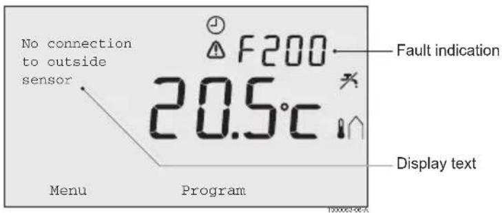

7.1 Fault messages
F200: No connection to outside sensor
| Fault indication | code F200⚠️ and ⚡️ are lit up. |
| Display text No connection to outside sensor. | |
| Solution Check the boiler's connection to the outside temperature sensor. | |
F203: Faulty connection to boiler
| Fault indication | code F203is lite up |
| Display text Communication fault. Check the connection. | |
| Solution Check the connection to the boiler. | |
F214: Incorrect room temperature reading
| Fault indication | code F214is lite up |
| Display text Room temperature is out of measuring range or sensor is defective. | |
| Solution Room temperature reading is incorrect. If the room temperature is between -5°C and 65°C, the temperature sensor may be faulty.Contact your installer. | |
F215: Thermostat failure
| Fault indication | code F215⚠ is lite up |
| Display text Internal fault. Thermostat failure. | |
| Solution Contact your installer. | |
EN
F216: No connection with base station (Thermostat RF only)
| Fault indication | code F216(●) and ⚠ are lite up |
| Display text Wireless | communication fault. |
| Solution Check whether | the base station for the boiler is on and is functioning correctly (consult the transmitter manual if necessary). If there is no connection between the thermostat and base station, then restore the connection as follows:- Put the base station in connection mode. Consult the base station manual for this.- On the thermostat select Menu > Settings > Users > Connection.If this does not solve the problem, look for another location for the thermostat and/or base station or remove “obstacles” that could interfere with the RF signal. |
F227: Wait for RF sensor
| Fault indication | code F227Wait for RF sensor. |
| Display text Wait for RF | Sensor information. This may take 15 mins |
| Solution This fault code | may appear after the thermostat RF is restarted, e.g.after changing the battery.As soon as the thermostat RF has received a message from the connected RF sensors, the message will disappear.If the RF sensors fail to report, another fault code will be displayedafter 15 minutes. |
Water pressure too low
| Fault indication | [IMAGE] and [IMAGE] are lite up |
| Display text The water | pressure in your central heating system is too low. |
| Solution Top up the water | water in the central heating system. See the documentation for your boiler. |
E-code: boiler failure
| Fault indication | eis lite up |
| Display text Boiler failure | Consult the fault table for the boiler, or for appliances between the thermostat and the boiler. |
| Solution Use the E-code | to find the fault in the appliances to be controlled, e.g. boiler, cascade controller or c-Mix. |
Thermostat batteries flat
| Fault indication | ⚠️ and ⚡ are lite up. |
| Display text - | |
| Solution The batteries | are almost empty. Replace the three AA batteries. |
7.2 Service message
Boiler service required
| Fault indication | f is lite up |
| Display text Maintenance | ce service type (A, B or C) required. Contact your installer.Telephone number: |
| Solution Contact your | installer to have the central heating boiler serviced. |
8. Problems and solutions
| Problem | eating is coming on too early in the morning. |
| Solution | Adjust the Max. pre-heat time setting (see the installation and service manual).The home may well not be up to temperature on time as a result. |
| Problem | not warm on time. |
| Solution - Open the | radiator valve further when the radiators warm up.- Increase theMax. pre-heat time(see the installation and service manual).- Increase the desiredHeating rateby adjusting this toFastest, for example (see the installation and service manual).For weather-compensated control you have the following options:- Set the radiator thermostat valves correctly.- Adjust the heating curve (see the installation and service manual).- Change the control strategy (see the installation and service manual).).There may also be technical problems with the central heating installation. In that case contact your installer. |
| Problem | too warm. |
| Solution Weather-compensated control means that no account is taken of the measuredroom temperature. Solve the problem in one of the following ways:- Set the radiator thermostat valves correctly.- Reduce the heating curve (see the installation and service manual).- Change the control strategy (see the installation and service manual).Room control may mean that the heat up rate is too high or that the thermostat is not correctly calibrated. | |
| Problem | es not become warm enough. |
| Solution Weather-compensated control means that no account is taken of the measuredroom temperature. Solve the problem in one of the following ways:- Set the radiator thermostat valves correctly.- Increase the heating curve (see the installation and service manual).- Change the control strategy (see the installation and service manual). | |
| Problem | ng for the tap water to get up to temperature. |
| Solution - Boiler: the DHW standby function may be switched off.In that case the symbol ✗ is shown in the display.Control the DHW standby with the DHW standby setting (see the installation and service manual).- Boiler: the boiler may be heated up too late.Set the tap water temperature using the DHW(see the installation and service manual). | |
| Problem | plies no hot water or hot water only briefly. |
| Solution | The DHW standby function ✗ may be switched off.Switch the DHW standby function to Continuous (see paragraph 6.1). |
EN
| Problem | Arts heating the home or the tap water at night even though the thermostat is set low. |
| Solution - Weather-compensated control (OTC) means that the boiler is controlled led by the outside temperature. This can be prevented by adjusting the Heat limit night or selecting another control strategy. See the installation and service manual.- The boiler can start pre-heating before the following set point. Adjust the Max. pre-heating time setting (see the installation and service manual).The home may well not be up to temperature on time as a result.- The tap water is only heated when the room temperature set is higher than the night temperature. See the installation and service manual for details of how to change the night temperature. |
| Problem | ure measurement differs from that which I am used to. |
| Solution | Correct the temperature measurement via the Calibration setting (see the installation and service manual). |
| Problem | does not function. |
| Solution Thermostat O | OpenTherm: your boiler may not support OpenTherm Smart Power. Thermostat RF: insert (full) batteries. |
| Problem | for the display does not work. |
| Solution Thermostat O | OpenTherm: your boiler may not support OpenTherm Smart Power. In that case fit batteries in the thermostat (see paragraph 3.2). Thermostat RF: insert (full) batteries. |
9. Technical specifications
| Dimensions | |
| 96 x 144 x 34 (l x w x h) in mmHeight excluding buttons 96 x 144 x 25 (l x w x h) in mm | |
| Power supply | |
| Thermostat OpenTherm | Via OpenTherm |
| Thermostat RF | Via batteries or loose 5 V DC adapter |
| Electrical connection | |
| Thermostat OpenTherm | OpenTherm communication. Connection for low-voltage wires |
| Thermostat RF | Bi-directional secure communication |
| Batteries | 3 x AA batteries. Lifetime: dependent on the brand of battery |
| Digital input | Potential-free contact (switch) |
| Ambient conditions | |
| Storage conditions | Temperature: -25°C – 60°C |
| Relative humidity: 5% – 90%, no condensation | |
| Operating conditions | Without batteries: 0°C – 60°C. With batteries: 0°C – 55°C |
| Temperature | |
| Room temperature | Measurement range: -5°C – 65°C |
| Maximum temperature deviation at 20°C: 0.3°C | |
| Outside temperature | The measurement is taken in the boiler and passed to the thermostat. Consult the boiler documentation regarding the accuracy of the measurement. |
| Set temperature range 5 – 35°C | |
| Calibration options Inside and outside temperature sensor: -5 to + 5 in steps of 0.5°C | |
| Control Modulating temperature control | |
| The control can be optimised | |
| Room control Overshoot: maximum 1°C after pre-heating | |
| Temperature variation: less than 0.25°C | |
| Control strategies Room temperature control | |
| Weather-compensated control | |
| 4 combination options | |
| Features of the thermostat | |
| Backlight Colour: blue | |
| Date/time indication Time: 24 h clock. Accuracy: to about 365 seconds per year | |
| Date: day – month – year | |
| Automatic switching to summer time | |
| Programs 2 clock programs with 6 switch points per day | |
| Boiler clock program with 6 switch points per day | |
| 16 holiday programs | |
| Day, Night, Frost protection, Summer mode, Fireplace | |
| Setting accuracy | Temperature: 0.5°C. |
| Clock program: 10 minutes | |
| Wireless range (Thermostat RF) | The range of the thermostat RF in buildings is generally 30 metres.The range is influenced strongly by the prevailing situation. (see paragraph 3.1) |
| Operation | Menu-controlled using push buttons and a push-turn button |
| Installation | Directly on the wall using screws or built-in junction box as per standards. |
| Built-in system possible using built-in part (art. S100994) | |
| Quality marks and compliance with standards | EMC:2004/108/EC – EN50165(1997), 55014, 55022 |
| Emission EN61000-6-3 | |
| Immunity EN61000-6-2 | |
| Drop test: IEC 68-2-32 | |
| RoHS compliant | |
| OpenTherm V3.0 SmartPower (Thermostat OpenTherm only) | |
| ETSI 300-220 (Thermostat RF only) | |
| Protection class | IP20 for wall installation, IPx4 for the built-in system. |
Appendix: clock program template
| Time | MO. TU. WE. TH. FR. SA. SU. | MO. TU. WE. TH. FR. | |||||||||||||
| 00._12._ | |||||||||||||||
| 01._13._ | |||||||||||||||
| 02._14._ | |||||||||||||||
| 03._15._ | |||||||||||||||
| 04._16._ | |||||||||||||||
| 05._17._ | |||||||||||||||
| 06._18._ | |||||||||||||||
| 07._19._ | |||||||||||||||
| 08._20._ | |||||||||||||||
| 09._21._ | |||||||||||||||
| 10._22._ | |||||||||||||||
| 11._23._ | |||||||||||||||
① Switch points can be set to a precision of 10 minutes. Enter the switch points as required.
Table des matières
natural_image
Illustration of a hand interacting with a circular device, showing rotational motion (no text or symbols)FR
3. Installation
3.1 Emplacement du thermostat
natural_image
Illustration of a hand holding a device with arrows indicating motion (no text or symbols)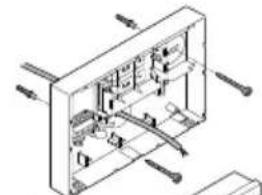
natural_image
Isometric technical diagram of a mechanical assembly with no visible text or symbols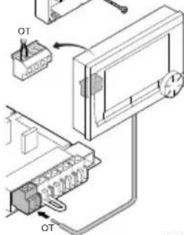
natural_image
Isometric technical diagram of a mechanical assembly with no visible text or symbolsnatural_image
Illustration of a hand pointing at a circular component with rotational arrows (no text or symbols)3. Installation
3.1 Installationsort des Thermostat
natural_image
Illustration of a hand holding a device with arrows indicating motion (no text or symbols)natural_image
Isometric technical diagram of a mechanical or electrical assembly with no visible text, numbers, or symbols.E-code: Ketelstoring
www.dedietrich-heating.com
39 rue Jacciano 5/26
L-2010 LUXEMBOURG
20-352122401401

VAN MARCKE
www.vamarcha.hz
Wedgevoerdenban 5
B-8500 KORTRUK
432156297511

DE DIETRICH
www.dodietrich-otoplanie.ru
12907 r. Morasa
www.dodietrich-heating.com
Room 512, Tower A. Kelon Building
12A Guanghua Rd, Chaoyang District
C-100000 BEIJING
- +86 (0)108,581,4017
-55 01195.561.4016
-86 (0)106.581 2166
+86 01'08 581 4019
contact:@tedictn.com.cn
De Dietrich


OpenTherm®
CE
123100-070311

123100
- Inhoudsopgave
- Installatie
- Introduction
- Overview
- Display
- Most important pictograms Pictograms not shown
- Buttons
- Installation
- Location of the thermostat
- Thermostat RF
- Installation and connection
- Location of the outside sensor
- Room sensor (for thermostat RF only)
- Prior to first use
- Setting language, time and date
- Default setting
- Room control
- Clock program
- Setting
- Three usage modes
- Creating or changing a clock program
- Making an overview
- Creating a new clock program
- Changing an existing clock program
- Restoring the default settings
- Setting continuous temperatures
- Group control
- Setting the control strategy
- Specific settings for weather-compensated control
- Heating curve:
- ① See also see day/night temperature limit 12.4
- Setting a holiday program
- Other settings
- Using the thermostat
- Selecting program
- Temporarily changing the temperature
- Fireplace mode
- Information
- Messages
- Fault messages
- Service message
- Problems and solutions
- Technical specifications
- Table des matières
- Emplacement du thermostat
- Installationsort des Thermostat
- De Dietrich
Brand : DE DIETRICH
Model : OpenTherm 123100
Category : Thermostat