MDG22PN - Tumble drier MAYTAG - Free user manual and instructions
Find the device manual for free MDG22PN MAYTAG in PDF.

User questions about MDG22PN MAYTAG
0 question about this device. Answer the ones you know or ask your own.
Ask a new question about this device
Download the instructions for your Tumble drier in PDF format for free! Find your manual MDG22PN - MAYTAG and take your electronic device back in hand. On this page are published all the documents necessary for the use of your device. MDG22PN by MAYTAG.
USER MANUAL MDG22PN MAYTAG
COMMERCIAL HE DRYER INSTALLATION INSTRUCTIONS Gas
INSTRUCTIONS D'INSTALLATION D'UN SECHE-LINGE HE COMMERCIAL À gaz
natural_image
Line drawing of a washing machine with front panel and door (no text or symbols on the device itself)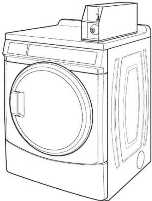
natural_image
Line drawing of a washing machine with front panel and door (no text or symbols)TABLE OF CONTENTS
DRYER SAFETY ....3 INSTALLATION INSTRUCTIONS - GAS DRYER ....9
DRYER DISPOSAL ....4 Install Leveling Legs....9
INSTALLATION REQUIREMENTS ....4 Make Gas Connection....9
Tools and Parts 4 Connect Vent 9
Location Requirements ....4 Complete Installation ....9
Electrical Requirements - Gas Dryer....MAINTENANCE INSTRUCTIONS ....10
Gas Supply Requirements 6TECHNICAL SPECIFICATIONS - GAS DRYER....10
Venting Requirements 7REVERSING THE DOOR SWING (OPTIONAL)....11
ELECTRONIC CONTROL SETUP ....13
WARRANTY....17
TABLE DES MATIERES
SECURITE DU SECHE-LINGE ......18 INSTRUCTIONS D'INSTALLATION -
ELIMINATION DU SECHE-LINGE ....19 SECHE-LINGE A GAZ....24
EXIGENCES D'INSTALLATION....19 Installation des pieds de nivellement....24
Your safety and the safety of others are very important.
We have provided many important safety messages in this manual and on your appliance. Always read and obey all safety messages.

This is the safety alert symbol.
This symbol alerts you to potential hazards that can kill or hurt you and others.
All safety messages will follow the safety alert symbol and either the word "DANGER" or "WARNING."
These words mean:
! DANGER
You can be killed or seriously injured if you don't immediately follow instructions.
WARNING
You can be killed or seriously injured if you don't follow instructions.
All safety messages will tell you what the potential hazard is, tell you how to reduce the chance of injury, and tell you what can happen if the instructions are not followed.
FOR YOUR SAFETY
- Do not use or store petrol or other flammable materials in this appliance or near this appliance.
- Do not spray aerosols in the vicinity of this appliance while it is in operation.
- Do not modify this appliance.
WARNING: Foryoursafety, the information in this manual must be followed to minimize the risk of fire ore explosion, ortoprevent property damage, personal injury, or death.
-Donotstoreorusepetrolorotherflammablevaporsandliquidsinthevicinityofthis oranyotherappliance.
-WHATTODOIFYOUSMELLGAS:
- Donottrytolightanyappliance.
- Donottouchanyelectricalswitch;donotuseanyphoneinyourbuilding.
- Cleartheroom, building, or area of allooccupants.
- Immediatelycallyourgassupplierfromaneighbor'sphone.Followthegassupplier's instructions.
- If you cannot reach your gassupplier, call the fire department.
-Installationandservicemustbeperformedbyaqualifiedinstaller,serviceagency,or thegassupplier.
DRYER DISPOSAL
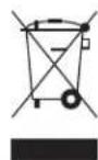
This appliance is marked according to the European directive 2002/96/EC on Waste Electrical and Electronic Equipment (WEEE).
By ensuring this product is disposed of correctly, you will help avoid potential negative consequences for the environment and human health, which could otherwise be caused by inappropriate waste handling of this product.
The symbol on the product, or on the documents accompanying the product, indicates that this appliance may not be treated as household waste. Instead it shall be handed over to the applicable collection point for the recycling of electrical and electronic equipment.
Disposal must be carried out in accordance with local environmental regulations for waste disposal.
For more detailed information about treatment, recovery and recycling of this product, please contact your local city office, your household waste disposal service or the shop where you purchased the product.
INSTALLATION REQUIREMENTS
Tools and Parts
Gather the required tools and parts before starting installation. Read and follow the instructions provided with any tools listed here.
Tools needed:
■200 mm (8") or 250 mm (10") Pipe wrench
■200 mm (8") or 250 mm (10") Adjustable wrench
■Flat-blade screwdriver
■Phillips screwdriver
■Adjustable wrench that opens to 25 mm (1") or hex-head socket wrench
Level
■8 mm (5/16") socket wrench
■Utility knife
■Vent clamps
■Pipe-joint compound resistant to LP gas
■Sealing gun and sealing compound (for installing new exhaust vent)
■Pliers
■Stiff-bladed putty knife
Parts supplied:
Remove parts bag from dryer drum. Check that all parts included.
■Foot boot (4)
■Dryer foot (4)
■PD models: Cam for service door lock
■PN models: Card reader bezel, card reader wire harness, hardware
NOTE: The circuit diagram for this dryer is located inside lower front panel, within the Tech Sheets.
Location Requirements
WARNING
Explosion Hazard
Keep flammable materials and vapors, such as petrol, away from dryer.
Do not install in a garage.
Failure to do so can result in death, explosion, or fire.
If installing a gas dryer:
IMPORTANT: Observe all governing codes and ordinances.
Check code requirements: Some codes limit or do not permit installation of clothes dryers in garages, closets, or sleeping quarters. Contact your local building inspector.
■Make sure that lower edges of the cabinet, plus the back and bottom sides of the dryer, are free of obstructions to permit adequate clearance of air openings for combustion air. See "Recessed Area and Closet Installation Instructions" below for minimum spacing requirements.
■Do not install on carpet.
NOTE: The dryer must not be installed in an area where it will exposed to water and/or weather.
Recessed Area and Closet Installation Instructions
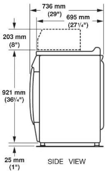
Product Dimensions 686 mm (27") dryer
This dryer may be installed in a recessed area or closet.
This dryer must not be installed behind a lockable door, a sliding door, or a door with a hinge on the opposite side to that of the dryer.
The installation spacing is in millimeters and is the minimum allowable. Additional spacing should be considered for ease of installation, servicing, and compliance with local codes and ordinances.
If installed in a closet with a door, the minimum unobstructed air opening in the top and bottom is required. Louvered doors with equivalent air openings are acceptable.
The dryer must be exhausted outdoors.
No other fuel-burning appliance may be installed in the same closet as the dryer.
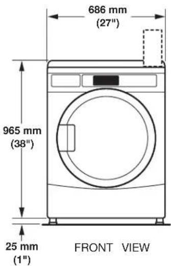
Minimum Installation Clearances
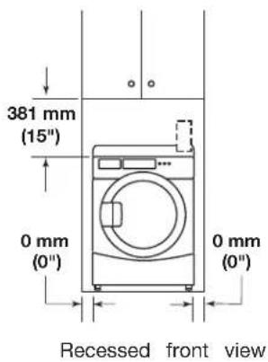
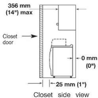
Additional clearances for wall, door, and floor moldings may be required or if external exhaust elbow is used.
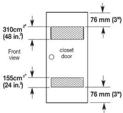
*Opening is the minimum for a closet door. Louvered doors with equivalent air openings are acceptable.
Electrical Requirements - Gas Dryer
Important: Observe all governing codes and ordinances.
You will need an earthed electrical outlet located within (2 feet) of either side of the dryer.
This dryer is supplied/fitted with an electricity supply cord and plug-cord.
It should be connected to electricity supply socket at the voltage shown on the rating plate. The minimum supply fuse capacity should be 5A. The dryer must be positioned so that the plug is accessible. If the fitted plug is not used, the electrical connection must be carried together.
by a competent electrician in accordance with local or national codes.
If the supply cord is damaged, it must be replaced with a specially terminated cord by an authorized service agent or a similarly compete person in order to avoid a hazard.
Do not use an adapter.
Do not use an extension cord.
NOTE: In accordance with the European EMC Directive (2004/108/E)
the maximum electricity supply system impedance to which the gas dryer should be connected is declared to be 0.29 Ohm + j0.18 Ohm
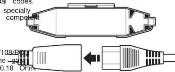
Using the universal cord included with this dryer:
The gas dryer is equipped with a universal cord with interchangeable plugs.
610 To use the universal cord, select the plug end that fits your electrical outlet, and plug it into the adapter on the
and supply-cord.
e voltage 2. See the plug end in place on the cord by aligning pacity should the 2 over halves over the cord adapter and clipping is accessible if st be carried out. them together.
natural_image
Top-down schematic of a mechanical component or housing (no text or symbols)WARNING

Electric Shock Hazard
This is a 3-wire appliance which must be earthed.
Do not earth to a gas pipe.
Do not change the power supply cord plug. If it does not fit the outlet, have a proper outlet installed by a qualified electrician.
Do not use an extension cord with this dryer.
Failure to follow these instructions could result in death, fire, or serious injury.
If codes permit and an additional earth bond wire is used recommended that a qualified electrician determine that the bond path is adequate.
EARTHING INSTRUCTIONS
■ For an earthed cord-connected dryer:
This dryer must be earthed. In the event of a malfunction or breakdown, earthing will reduce the risk of electric shock by providing a path of least resistance for electric current. This dryer is equipped with a cord having an equipment-earthing conductor and a earthing plug. The plug must be plugged into an appropriate outlet that is properly installed and earthed in accordance with all local codes and ordinances.
WARNING: Improper connection of the equipment-earthing conductor can result in a risk of electric shock.
Check with a qualified electrician or service representative or personnel if you are in doubt as to whether the dryer is properly earthed. Do not modify the plug provided with the dryer: if it will not fit the outlet, have a proper outlet installed by a qualified electrician.
SAVE THESE INSTRUCTIONS
Gas Supply Requirements
WARNING

Explosion Hazard
Connect this dryer to a regulated gas supply. Supply pressure must be in accordance with the Technical Specifications (see last page).
enstall a shut-off valve.
Securely tighten all gas connections.
If connected to LP, have a qualified person make sure gas pressure is correct.
Failure to do so can result in death, explosion, or fire.
IMPORTANT: Observe all governing codes and ordinances.
Gas Supply
Before installation, check that the local gas distribution conditions, nature of gas and pressure, and the adjustment of the appliance are compatible. Burner information will be found on the model/serial rating plate in the door recess of the dryer. If this information does not agree with the type of gas available, see your dealer.
Natural Gas:
This dryer is factory adjusted for use with NATURAL GAS (G20), and no further adjustment should be required at installation.
L.P. Gas:
This dryer is also certified for use with L.P. (propane or gases with appropriate conversion. No attempt shall be ma convert the appliance from the gas specified on the mode rating plate for use with a different gas without consulting serving gas supplier.
Conversion must be done by a competent service technician. Gas conversion kit, part number W10233219, is available for purchase from your dealer. Full instructions are supplied with the kit.
Natural gas (France/Belgium):
This dryer is also certified for France/Belgium for use with G20/G25 gases (20 mbar/25 mbar) with appropriate convers. No attempt should be made to convert this appliance from gas specified on the gas rating label for use with a different without consulting the serving gas supplier. Gas conversion is done by a qualified gas service technician. Conversion number (W10181947) is available for purchase from your department. Full instructions are supplied with the kit.
Supply line requirements:
Provide a rigid gas supply line to the dryer location. It shows minimum 12.5 mm (1/2") ID. When acceptable to the gas and local codes, 10 mm (3/8") ID rigid supply line may be for lengths under 6.1 m (20'). Pipe-joint compounds resistant the action of L.P. gas must be used.
Gas connection to the dryer itself should be made by me a flexible gas hose suitable for the appliance and gas cat in accordance with national installation regulations. If in doubt contact the gas supplier. It should be minimum 10 mm (3 A means of restraint should be used between the appliance the wall to prevent straining of the rigid gas supply when appliance is moved. An appropriate length of chain and a hook is recommended.
The dryer gas inlet connection is a 3/8" NPT thread. An supplied for conversion to standard ISO.228-1 thread (3/8). Check for leaks by using an approved noncorrosive leak-detection solution. Bubbles will show a leak. Correct any found. A pressure measurement tapping is provided on the gas valve within the dryer, accessible after removal of the front panel.
The dryer must be disconnected from the gas supply system during any pressure testing of that system.
Venting Requirements
WARNING
de to /serial the

Fire Hazard
Use a heavy metal vent.
Do not use a plastic vent.
Do not use a metal foil vent.
Failure to follow these instructions can result in death the of fire.
nt gas
must
WARNING: To reduce the risk of fire, this dryer MUST be dealer EXHAUSTED OUTDOORS.
■Gas dryers should only be installed in a room if the room meets the appropriate ventilation requirements specified in the national installation regulations. Make sure the room containing the dryer has an adequate air supply for gas supplier combustion and drying operation. A window or equivalent means of ventilation must be opened in the room when the dryer is in use (an equivalent form of opening includes an adjustable louver, hinged panel, or other means of ventilating means that opens directly to outside air). Adequate ventilation has a category provided to avoid the backflow of gases into the room doubt, other fuel-burning appliances, including open fires (i.e. availa 3/8" airflow into the room should match airflow out from the room). The design of the flue system should be such that any condition formed when operating the dryer from cold shall either be used and subsequently re-evaporated or discharged. Following these instructions should adequately meet this requirement.
The dryer vent must not be discharged into a flue which is used for exhausting fumes from appliances burning gas other fuels, chimney, wall, ceiling, or a concealed space of building, or any other vent used for venting.
Do not use an exhaust hood with a magnetic latch.
■Do not install flexible metal vent in enclosed walls, ceilings, lower floors.
■102 mm (4") heavy metal vent and clamps must be used.
Use clamps to seal all joints. Vent must not be connected secured with screws or other fastening devices which extend into the interior of the vent and catch lint. Do not use c
IMPORTANT: Observe all governing codes and ordinances.
Use a heavy metal vent. Do not use plastic or metal foil ve Rigid metal vent is recommended to avoid crushing and kinkir Flexible metal vent must be fully extended and supported whe the dryer is in its final position. Remove excess flexible metal to avoid sagging and kinking that will result in reduced airflow and poor performance.
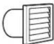
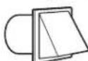
An exhaust hood should cap the vent to keep rodents and insects from entering the building.
Exhaust hood must be at least 305 mm (12") from the grouf or any object that may be in the path of the exhaust (such flowers, rocks, or bushes).
If using an existing vent system, clean lint from the entire le of the system and make sure exhaust hood is not plugged v lint. Replace any plastic or metal foil vent with rigid metal or flexible metal vent.
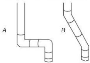
Plan installation to use the fewest number of elbows and
natural_image
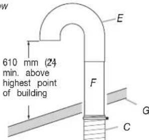
Two pipe elbow diagrams labeled A and B, showing different structural layers (no text or symbols beyond labels)Exhaust Air Flow
A. Good
B. Better
Allow as much room as possible when using elbows or making turns. Bend vent gradually to avoid kinking.
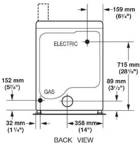
Vent outlet is located at the center of the bottom dryer back.
The vent can be routed up, down, left, right, behind the dryer, or straight out the back of the dryer.
Vent System Length
Maximum length of vent system depends upon the type used, number of elbows, and type of exhaust hood.
Maximum Vent Length
102 mm (4") Exhaust Hoods
Box Louvered
64 mm 1/2) Angled
Rigid Metal Vent

| No. of 90° turns | Box | Hood and Louvered Style | Angled Hood Style |
| 0 | 39.6 m (130 ft.) | 39.3 m (129 ft.) | |
| 1 | 38.1 m (125 ft.) | 36.3 m (119 ft.) | |
| 2 | 35.1 m (115 ft.) | 33.2 m (109 ft.) | |
| 3 | 32.3 m (106 ft.) | 30.5 m (100 ft.) | |
| 4 | 98 m (98 ft.) | 28 m (92 ft.) | |
If dryer is installed in a confined area, such as a bedroom, bathroom, or closet, provision must be made for enough air for combustion and ventilation. (Check governing codes and ordinances.) See “Recessed Area and Closet Installation Instructions” in the “Location requirements” section.
A 102 mm (4") outlet hood is preferred. However, a 64 mm
(2½") outlet exhaust hood may be used. A 64" mm (2
outlet creates greater back pressure than other hood types.
For permanent installation, a stationary vent system is requi
Multiple Dryer Venting
■A main vent can be used for venting a group of dryers.
vent should be sized to remove 5663 l/min (200 CFM) d POaing per dryer. Large-capacity lint screens of proper design may be used in the main vent if checked and cleaned frequently. The room where the dryers are located should have make-up air equal to or greater than the airflow of all the dryers in the room.
A back-draft damper kit is needed and is available from a commercial laundry distributor; it should be installed in the vent of each dryer to keep exhausted air from returning into the dryers and to keep the exhaust in balance within the main vent. Unobstructed return air openings are required.
tErash vent should enter the main vent at an angle pointing in 1 direction of the airflow. Vents entering from the opposite side should be staggered to reduce the exhausted air from interfering with the other vents.
The maximum angle of each vent entering the main vent should be no more than 30^ .
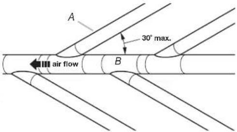
A. Individual dryer vent
B. Main vent
Keep air openings free of dry cleaning fluid fumes. Fumes creat acids which, when drawn through the dryer heating units, can damage dryers and items being dried.
of A vent A clean-out cover should be located on the main vent for periodic cleaning of the vent system.
If an exhaust hood cannot be used:
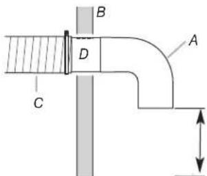
Min.300 mm12") clearance above any accumulation of snow, ice, or debris such
A. Exhaust hood or elbow
B. Wall
C. Main collector vent
D. Horizontal vent
E. 180° sweep elbow
F. Vertical vent G. Roof
The outside end of the main vent should have a sweep elbow directed downward. If the main vent travels vertically through the roof, rather than through the wall, install a 180° sweep elbow of the end of the vent at least 610 mm (2 ft.) above the highest of the building. The opening in wall or roof shall have a diameter 13 mm½") larger than the vent diameter. The vent should be
centered in the opening.
Do not install screening or cap over the end of the vent.
INSTALLATION INSTRUCTIONS - GAS DRYER
Install Leveling Legs
WARNING
Excessive Weight Hazard
Use two or more people to move and install dryer.
Failure to do so can result in back or other injury.
Connect Vent
- Using a 102 mm (4") clamp, connect vent to exhaust outlet in dryer. If connecting to existing vent, make sure the vent clean. The dryer vent must fit over the dryer exhaust outlet and inside the exhaust hood. Make sure the vent is secured to exhaust hood with a 102 mm (4") clamp.
- Move dryer into final position. Do not crush or kink vent. Measure dryer is level.
- Check to be sure there are no kinks in the flexible gas line
NOTE: Slide dryer onto cardboard or hardboard before moving to avoid damaging floor covering.
- Using two or more people, move dryer to desired installation location.
- Take tape off front corners of dryer. Open dryer and rem the literature and parts packages. Wipe the interior of the drum thoroughly with a damp cloth.
- Take two of the cardboard corners from the carton and them on the floor in back of the dryer. Firmly grasp the of the dryer and gently lay it on its back on the cardboard corners.
- With one of the legs in hand, check the ridges for a diamond marking. That's how far the leg is supposed to go into the hole.
- Start to screw the leveling legs into the holes by hand. a small amount of liquid detergent to lubricate the screw threads so it is easier to turn the legs.) Use a 1" (25 wrench or socket wrench to finish turning the legs until reach the diamond mark. Then fit a protective foot boot each foot.
- Now stand the dryer up.
- Remove cardboard or hardboard from under dryer. Adjust legs of the dryer up or down until the dryer is level.
place
Use
nm)
I over
Complete Installation
- With dryer in final position place level on top of the moving dryer, first side to side; then front to back. If the dryer is not level, adjust the legs of the dryer up or down until the dryer is level.
WARNING

Electric Shock Hazard
youThis dryer must be earthed.
Securely tighten all electrical connections.
Failure to do so can result in death, fire, or electric shock.
Make Gas Connection
WARNING
Excessive Weight Hazard
Use two or more people to move and install dryer.
Failure to do so can result in back or other injury.
- Plug into an earthed outlet.
- Check dryer operation:
Press the selection button for a full cycle and let the dryer for at least five minutes. Dryer will stop when time is used
NOTE: Dryer door must be closed for dryer to operate.
When door is open, dryer stops, but timer continues to run. To restart dryer, close door and press a cycle button.
-
If the burner does not ignite and there is no heat inside the dryer, shut off dryer for five minutes. Check that all gas sup valves are in the "ON" position and that the electrical cord plugged in. Repeat five-minute test.
-
Remove red cap from gas pipe.
- Connect gas supply to dryer. If the flexible gas hose has 3/8" BSP thread, use the supplied conversion thread adapter. Use pipe-joint compound resistant to the action of L.P. gas for gas connections.
If necessary for service, open the toe panel. Use a putty knife to press on the 2 toe panel locks located at the top of the toe panel. Pull downward on the toe panel to open. Toe panel is hinged at the bottom.
- Open the shutoff valve in the gas supply line.
- Test all connections by brushing on an approved noncorrosive leak-detection solution. Bubbles will show a leak. Correct any leaks found.
MAINTENANCE INSTRUCTIONS
Maintenance instructions:
■Clean lint screen after each cycle.
■Removing accumulated lint:
• From inside the dryer cabinet:
Lint should be removed every 2 years or more often, depending on dryer usage. Cleaning should be done by a qualified person.
• From the exhaust vent:
Lint should be removed every 2 years, or more often depending on dryer usage.
If dryer does not operate, check the following:
■Electric supply is connected.
■Circuit breaker is not tripped or fuse is not blown.
■Door is closed. Listen closely to hear door switches activate.
■Selected cycle button has been pressed firmly and display shows cycle time.
■Check that gas supply shutoff valves are set in open positio
If you need assistance:
Contact your authorized Maytag Commercial Laundry distributor or visit: www.MaytagCommercialLaundry.com. When you call, you will need the dryer model number and serial number. Both numbers can be found on the serial-rating plate located on your appliance.
| 220-240V~50Hz 1ph 3A max. IP24 Clothes capacity: 9.0 kg max. | ||
| Factory set for NATURAL GAS: Injector size: 2.2 mm Heat input gross: 5.9 kW | ||
| European Country: | CH, CZ, CY, ES, GB, GR, HR, IE, IT, PT, SI, SK, TR | CY, CZ, DK, EE, FI, GR, HU, IT, NO, RO, SE, SK, TR |
| European Gas Category: | II_2H3+ | II_2H3B/P |
| Gas Flow Rate: | 0.562703 m^3/hr | 0.562703 m^3/hr |
| Supply Pressure (G20): | 20 mbar | 20 mbar |
| Factory Adjusted Pressure: | 7.4 mbar 7.4 mbar | |
| With LP Gas Conversion Kit: Injector size: 1.25 mm Heat input gross: 6.4 kW | ||
| European Country: | CH, CZ, CY, ES, GB, GR, HR, IE, IT, PT, SI, SK, TR | CY, CZ, DK, EE, FI, GR, HU, IT, NO, RO, SE, SK, TR |
| European Gas Category: | II_2H3+ | II_2H3B/P |
| Butane Supply Pressure (G30): | 28-30 mbar | 30 mbar |
| Adjusted Pressure: | N/A N/A | |
| Propane Supply Pressure (G31): | 37 mbar 30 mbar | |
| Adjusted Pressure: | N/A | N/A |
| With France/Belgium NATURAL GAS conversion kit: Injector size: 1.65 mm Heat input gross: 5.9 kW | ||
| European Country: | FR, BE | |
| European Gas Category: | I_2E+ | |
| Supply Pressure (G20): | 20 mbar | |
| Supply Pressure (G25): | 25 mbar | |
| Adjusted Pressure: | N/A | |
| NOTE: Conversion kit : From Natural Gas to LP Gas : Whirlpool Part No. W10233219. Conversion kit : From Natural Gas to Natural Gas - France/Belgium: Whirlpool Part No. W10184947. Manufacturer : Whirlpool Corporation, Benton Harbor, Michigan 49022, USA. | ||
REVERSING THE DOOR SWING
Door swing can be changed from a right-side opening to left-rotate outer door 180°. opening, if desired.
Place a towel or soft cloth on top of the dryer or work space to avoid damaging the surface.
Remove the Door Assembly
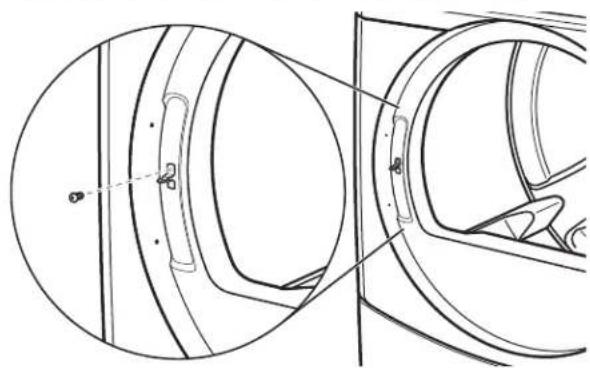
- Remove 3 of the 4 screws that hold the door hinge on the front panel of the dryer. Partially loosen the remaining screw with keyhole opening and lift the door off the screw.
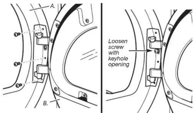
A. Dryer front panel
B. Door assembly
- Lay the door assembly on a previously prepared flat surface with the inside (inner door assembly) facing up.
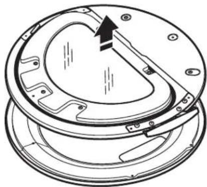
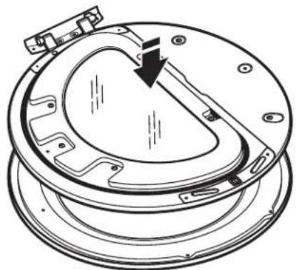
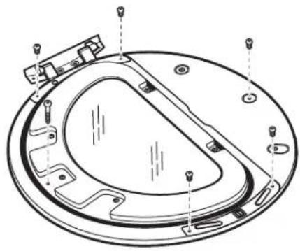
- Remove the 6 Phillips head screws to release the outer door assembly from the inner door assembly, as indicated below. See illustration. It is important that you remove only the 6 indicated screws.
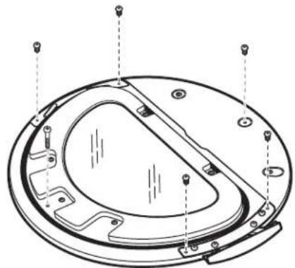
natural_image
Technical line drawing of a circular mechanical component with mounting holes and internal features (no text or symbols)- Lift the inner door assembly off the outer door assembly.
natural_image
Technical line drawing of a mechanical component with a circular housing and internal components (no text or symbols)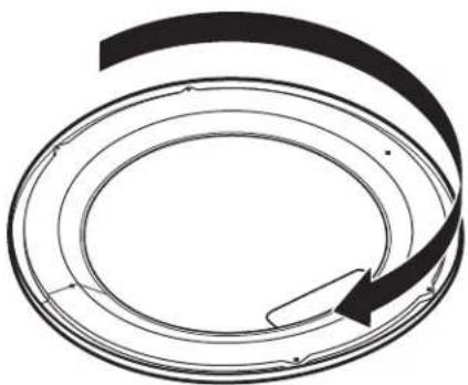
natural_image
Abstract circular diagram with concentric rings and a curved arrow, no text or symbols presentReverse Hinge
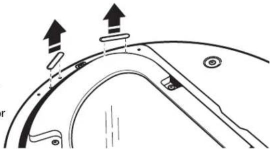
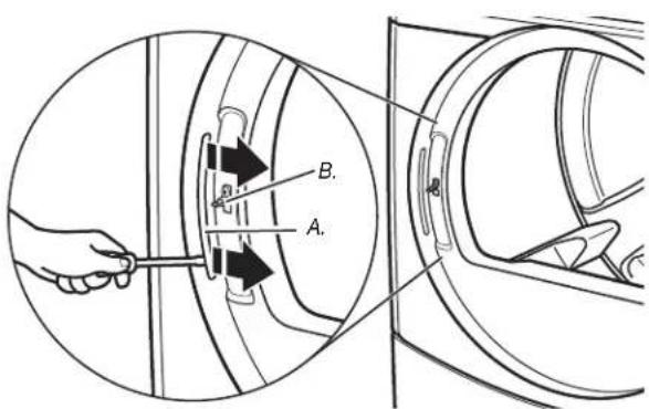
- Use a small flat-blade screwdriver to remove 2 plug strips from the inner door. Slide the head of the screwdriver under the plugs, being certain not to scratch the inner door surface. Lift up.
natural_image
Technical diagram of a mechanical component with two upward arrows indicating motion or force direction (no text or symbols present)- Remove the 4 screws that attach to the inner door hinge and move the hinge to the other side. Reinstall the 4 screws.
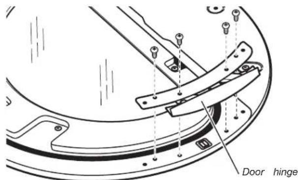
- Reinstall plug strips on opposite side of the inner door.
-
Check for fingerprints on the glass. Clean glass if necessary.
-
Place the inner door assembly inside the outer door assembly remove the strike using a Phillips screwdriver. To fit correctly, the inner door assembly edge fits completely inside the outer door assembly edge.
natural_image
Technical line drawing of a mechanical component with a curved arrow indicating direction (no text or symbols)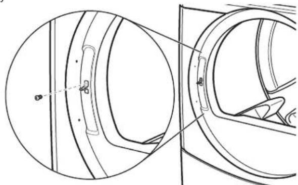
natural_image
Technical line drawing of a mechanical component with cross-sectional view (no text or symbols)-
Insert strike on the opposite side.
-
Reassemble the inner and outer door assemblies with the 6 screws.
natural_image
Technical line drawing of a circular mechanical component with mounting holes and internal features (no text or symbols)Reinstall the door
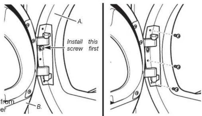
- Reattach door to dryer front panel with the 4 screws. Partially install the screw with keyhole opening first, and fit the keyhole opening in the hinge over the screw. Then insta the remaining 3 screws and tighten all 4 screws.
Reverse the strike
- Use a small flat-blade screwdriver to remove plug strip from the dryer door opening. Slide the head of the screwdriver under the plugs, being certain not to scratch the dryer surface. Lift the plastic strip from the dryer slowly to avoid distortion of the plug strip.
A. Dryer front panel
B. Door assembly
-
Check for fingerprints on the glass. Clean glass if necessary.
-
Close door and check that it latches securely.
A. Plug strip
B. Door strike
ELECTRONIC CONTROL SETUP
WARNING

Electric Shock Hazard
Disconnect power before servicing.
Replace all parts and panels before operating.
Failure to do so can result in death or electrical shock.
IMPORTANT
Electrostatic Discharge (ESD)
Sensitive Electronics
ESD is present everywhere. ESD may damage or wea electronic control assembly. The new control assembly appear to work well after repair is finished, but failure occur at a later date due to ESD stress.
■ Use an anti-static wrist strap. Connect wrist strap to earth connection point or unpainted metal in the app
-OR-
Touch your finger repeatedly to a green earth connection or unpainted metal in the appliance.
■ Before removing the part from its package, touch the anti-static bag to a green earth connection point or unpainted metal in the appliance.
■ Avoid touching electronic parts or terminal contacts; electronic control assembly by edges only.
■ When repackaging failed electronic control assembly in anti-static bag, observe above instructions.
GENERAL USER INFORMATION
"out of order" showing in display
This condition indicates the dryer is inoperative. Diagnostic code will follow the scrolling message.
'0 Minutes' showing in display
This condition indicates the dryer cannot be operated. Coins dropped or debit inputs during this condition will be stored in escrow but cannot be used until normal operation is restored by opening and closing the door. If a door switch fails, it must be replaced before normal operation can be restored.
Cold Start (initial first use)
Dryer is programmed at the factory as follows:
■ 45 minutes dry time for PN models; 5 minutes per coin for PD models.
■ 1.50 dry price (fixed cycle with top off - PD Models).
■ 0.00 dry price (fixed cycle - PN Models).
Warm Start (after power failure)
A few seconds after power is restored, if a cycle was in progress at the time of the power failure, 'RESELECT CYCLE' will flash in the display. This is to indicate the need for a fabric setting button to be pressed to restart dryer.
Pricing
After the door is opened and closed following the completion of a cycle, the display indicates the cycle price (unless set for free operation). As coins or debit inputs arrive, the display will change to lead the user through the initiation of a cycle.
There are four (4) types of pricing:
Fixed 'Vend' Pricing
A dryer set up for 'Fixed Cycle' operation can only accept add time accumulated by increments equal to the length of a compl dry cycle. A maximum of 99 minutes may be purchased; no additional credit is given when 99 minutes is in the display.
Accumulator Pricing
If the price is set to one coin 1, then accumulator mode is in Cycle time can be purchased one coin at a time (PD models) the maximum time of 99 minutes.
mayFixed Cycle With Top Off Pricing
A dryer set to offer 'Top Off' capability will allow time to be a one existing dry cycle in increments equal to the number of minutes of dry time per coin (coin 1), up to 99 minutes, regardless of required to start the dryer. No credit is given for coins or debits entered when the control is displaying 99 minutes.
PN Models Set Up As PR: In Enhanced Debit Mode, the top price can be set independently (see VALUE OF COIN 2), and the off time is calculated according to the following equation:
handle off pricefull cycle price = off timefull cycle length
Hundredth increment offset is not applied to top off purchases.
PN Models
The factory has preset the cycle price to zero. When this happ 'SELECT CYCLE' will appear rather than a cycle price. Any cycle started as a free cycle will automatically terminate when the do is opened.
Debit Card Ready
or failure This dryer has a control that is debit card ready, but the dryer
CONTROL SET-UP PROCEDURES
IMPORTANT: Read all instructions before operating.
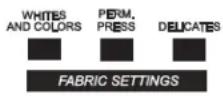
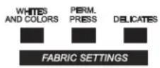
The fabric setting buttons along with the digital display are to set-up the dryer controls.
The display can contain 4 numbers and/or letters and a point. These are used to indicate the set-up codes and values available for use in programming the dryer.
How to use the buttons to program the controls
- The WHITES AND COLORS button is used to adjust the values associated with set-up codes. Pressing the button w increment the value by one (1). Rapid adjustment is possib by holding the button down.
- The PERM. PRESS button advances the display through the set-up codes. Pressing the button will advance the display to the next available set-up code. Holding the button down will automatically advance through the set-up codes at a rate of one (1) per
- The DELICATES button is used to select or deselect optic
Start Operating Set-Up
■ PD Models: Insert service door key, turn, and lift to remove access door.
■PN Models: Remove the AA1 jumper from the control board. SET-UP CODES
procedure below, or use the Service Access Code below. Once the
debit card reader is installed (according to the reader manufacturer's
instructions), the set-up mode can be entered by inserting a manual
set-up card (supplied by the reader manufacturer) into the The setup code is indicated by the one or two left hand char
If manual set-up card is not available, manual set-up mode set-up code value is indicated by the two or three right hand
be entered. However, diagnostic mode can be entered by removing
connector AA1 on the circuit board.
NOTE: The first line of each code indicates the factory default.
Once the FOR, PN, MODELS: The set-up codes are the same as for the manufacturer's models except where noted.
The setup code is indicated by the one or two left hand char setcapnode value is indicated by the two or three right hand NOTE: The first line of each code indicates the factory default.
IMPORTANT: The console must not be opened unless pow first removed from the dryer. To access connector AA1:
→ Unplug dryer or disconnect power.
→ Open console, disconnect plug on AA1, close console.
→ Plug in dryer or reconnect power.
■PN Models Equipped with Programming Switch: Insert ace panel key and turn counter-clockwise.
■PN Models with Gen. 2 Debit Card Reader: Once a Gen. 2 card reader is installed (according to the reader manufacturer instructions), the set-up mode can only be entered by insert a manual set-up card (supplied by the reader manufacturer) into the card slot.
If manual set-up card is not available, only diagnostic mode can be entered.
Alternate method of entering Set-up Mode by entering Service Access Code: This code can be entered to access set-up without removing the console on dryers just removed from carton, or not yet programmed. The Service Access Code functions on dryers set up for 0 vend price without any \$ Pricing set-up, and the Coin/Debit Option must be set to. If the dryer is not in failure mode, the door must be open proceed. Using only the three bottom buttons (numbered 1 and 3 from left to right):
- Press 2 for longer than 2 seconds but less than 10 seconds.
- Press 1 & 3 simultaneously for 2 seconds. Display shows S 3.
- Press 1 & 2 simultaneously. Display shows S 4.
- Press 2 & 3 simultaneously. Display shows S 5.
- Press 2.
- Wait at least 2 seconds, but not more than 15 seconds then press in succession: 3, 2, 1, 3.
The dryer is now in the set-up mode.
Before proceeding, it is worth noting that, despite all the or available, an owner can simply choose to uncrate a new co-dryer, hook it up, plug it in, and have a dryer that operate PD models require a payment system or OPL kit to be ins to operation.
■ PD dryers are pre-set at the factory for fixed cycle price with top off.
■PN dryers are pre-set for fixed cycle operation, and they can be run without payment.
with top off.
can be
DISPLAY
After the dryer has been installed and plugged in, the display shows '0 minutes.'
Once the dryer has been plugged in and the dryer door opened and closed, the display will show the vend price. PN models a factor-order reset for free cycles; the display will flash 'SELECT CY
PD Models


SET-up CODES
CODE EXPLANATION
| 606 | REGULAR CYCLE PRICE |
| 606 | Represents the number of coins (coin 1); may adjust from 0-39(See b.xx set-up for VALUE OF COIN 1). Advance from 0-39 bypressing WHITES AND COLORS. Factory default of 6 x coin 1. |
| 500→Press PERM. PRESS button once to advance to next code. | |
| 27 Debit ret's | REGULAR DRY TIME |
| 785 | Represents the number of minutes per coin (coin 1).Factory default of 5 minutes per coin.Example: 6 coins x 5 minutes = 30 minutes.By pressing the WHITES AND COLORS button, value adjustsfrom 1-99 minutes. |
| de | |
| vice45 | PN MODELS: Represents the cycle length for free cycles.As example: '7 45' = 45 minutes. |
| modethe only Press PERM. PRESS button once to advance to next code. | |
| Special "J" | TYPE OF DRYER PRICING |
| 800ened to 2. | Fixed Cycle with Top Off. For detailed description, see GeneralUser Information. |
| 8FC seconds. | Fixed Cycle. For detailed description, see General UserInformation.Use DELICATES button to make this selection.PN MODELS: Factory default of FC. |
| ws S 3. | |
| →Press PERM. PRESS button once to advance to next code. | |
| 900 | CYCLE COUNTER OPTIONThis option is either SELECTED 'ON' or NOT SELECTED 'OFF'. |
| 900 | Not Selected 'OFF'. |
| 80C commercial es. NOTE: | Selected 'ON' and not able to be deselected. Press DELICATESbutton 3 consecutive times to select 'ON'. Once selected 'ON'it cannot be deselected. |
| tailed prior | →Press PERM. PRESS button once to advance to next code. |
| Special | TYPE OF DRYER PRICING |
| "John" | Fixed Cycle with Top Off. For detailed description, see General User Information. |
| ened to 2. | |
| 8.FC | Fixed Cycle. For detailed description, see General User Information. |
| seconds. | Use DELICATES button to make this selection. |
| ws S 3. | PN MODELS: Factory default of FC. |
| →Press PERM. PRESS button once to advance to next code. | |
| is 900 | CYCLE COUNTER OPTIONThis option is either SELECTED 'ON' or NOT SELECTED 'OFF'. |
| 900 | Not Selected 'OFF'. |
| optional commercial es. NOTE | Selected 'ON' and not able to be deselected. Press DELICATES button 3 consecutive times to select 'ON'. Once selected 'ON' it cannot be deselected. |
| tailed prior | Press PERM. PRESS button once to advance to next code. |
| CODE EXPLANATION | |
| 1.00 | MONEY COUNTER OPTIONThis option is either SELECTED ‘ON’ or NOT SELECTED |
| 1.00 | Not Selected ‘OFF’. |
| 1.00 | Selected ‘ON’.Press DELICATES button 3 consecutive times to select ‘ and 3 consecutive times to remove (Not Selected ‘OFF’). Counter resets by going from ‘OFF’ to ‘ON’. |
| 1.00 | Selected ‘ON’ and not able to be deselected.To select ‘ON’ and not able to be deselected, first select then within two seconds press DELICATES twice, WHITE COLORS once, and exit the set-up mode.→ Press PERM. PRESS button once to advance to next code. |
| 2.00 | SPECIAL PRICING OPTIONThis option is either SELECTED ‘ON’ or NOT SELECTED |
| 2.00 | Not Selected ‘OFF’. |
| 2.5P | Selected ‘ON’. Press DELICATES button once for this selection. |
| If SPECIAL PRICING OPTION is selected, there is access to codes ‘3.’ through ‘9.’→ Press PERM. PRESS button once to advance to next code. | |
| OPTIONS TO USE IF SPECIAL PRICING IS SELECTED: | |
| 3.06 | SPECIAL CYCLE PRICE |
| 3.06 | Represents the number of coins (coin 1); may adjust from 0-39. (See b.xx set-up for VALUE OF COIN 1). Advance 0-39 by pressing WHITES AND COLORS. Factory default 6 x coin 1. |
| 3.00 | PN MODELS: Factory default of 0 coins.→Press PERM. PRESS button once to advance to next code. |
| 4.05 | SPECIAL DRY TIME |
| 4.05 | Represents the number of minutes per coin (coin 1).Factory default of 5 minutes per coin.Example: 6 coins x 5 minutes = 30 minutes.By pressing the WHITES AND COLORS button, the value can be adjusted from 1-99 minutes. |
| 4.45 | PN MODELS: Represents the cycle length for free cycles As example: ‘4 45’ = 45 minutes.→Press PERM. PRESS button once to advance to next code. |
| 5.00 | TIME-OF-DAY CLOCK, MINUTES |
| 5.00 | This is the TIME-OF-DAY CLOCK, minute setting; select minutes by pressing WHITES AND COLORS button.→Press PERM. PRESS button once to advance to next code. |
| 6.00 | TIME-OF-DAY CLOCK, HOURSNOTE: Uses the 24 hr. clock. |
| 6.00 | This is the TIME-OF-DAY CLOCK, hour setting; select 0-hours by pressing WHITES AND COLORS button.→Press PERM. PRESS button once to advance to next code. |
'OFF
'OFF
| CODE EXPLANATION | |
| OPTIONS TO USE IF SPECIAL PRICING IS SELECTED (continued): | |
| 7.00 | SPECIAL PRICE START HOURNOTE: Uses the 24 hr. clock. |
| 7.00 | This is the start hour, 0-23 hours. Select START HOUR by pressing WHITES AND COLORS button. |
| → Press PERM. PRESS button once to advance to next code. | |
| 8.00 | SPECIAL PRICE STOP HOURNOTE: Uses the 24 hr. clock. |
| 8.00 | This is the stop hour; 0-23 hours. Select STOP HOUR by pressing WHITES AND COLORS button. |
| → Press PERM. PRESS button once to advance to next code. | |
| 9.10 | SPECIAL PRICE DAY |
| 9.10 | This represents the day of the week and whether special pricing is selected for that day. A number followed by 'indicates no selection that particular day (9.10). A numb followed by an 'S' indicates selected for that day (9.1S)Days of week (1-7) can be chosen by pressing the WH AND COLORS button. Press DELICATES button once to select special pricing for each day chosen.When exiting setup code '9.', the display must show cu day of week:DISPLAY DAY OF WEEK CODE (selected)10 Day 1 = Sunday 1S20 Day 2 = Monday 2S30 Day 3 = Tuesday 3S40 Day 4 = Wednesday 4S50 Day 5 = Thursday 5S60 Day 6 = Friday 6S70 Day 7 = Saturday 7S |
| → Press PERM. PRESS button once to advance to next code. | |
| 8.00 | VAULT VIEWING OPTIONThis option is either SELECTED ‘ON’ or NOT SELECTED ‘OFF’. |
| 8.00 | Not Selected ‘OFF’. |
| 8.SC | Selected ‘ON’. Press DELICATES button once for this selection. When selected, the money and/or cycle counts will be viewable (if counting is selected) when the coin box is removed. |
| →Press PERM. PRESS button once to advance to next code. | |
| 6.05 | VALUE OF COIN 1 |
| 6.05 | This represents the value of coin 1 in the quantity of 5% increments of the larger coin value. 5 x 5% = 25%.By pressing the WHITES AND COLORS button, there is the option of 1-199 for the quantity of 5% increments.With coin slide activation, this represents the total vend price. |
| →Press PERM. PRESS button once to advance to next code. | |
| C.20 | VALUE OF COIN 2 |
| C.20 | This represents the value of coin 2 in the quantity of 5% increments of the larger coin value. 20 x 5% = 100%.By pressing the WHITES AND COLORS button, there is the option of 1-199 for the quantity of 5% increments. |
| C.05 | PN MODELS: This represents the value of coin 2 in the quantity of 5% increments of the larger coin value. Factory default = 5 x 5% of the larger coin value.PN MODELS USING ENHANCED DEBIT: This represents the value of top off in quantity of 5% increments of the larger coin value. Factory default = 5 x 5% of the larger coin value. |
| →Press PERM. PRESS button once to advance to next code. | |
| CODE EXPLANATION | |
| 8.00 | COIN SLIDE OPTIONThis option is either SELECTED ‘ON’ or NOT SELECTED Replacement of metercase will be needed for coin slide |
| 8.00 | Not Selected ‘OFF’. |
| 8.CS | Selected ‘ON’.NOTE: This option needs to be set to ‘00’ unless the metercase has been changed to accept a coin slide deviPress DELICATES button 3 consecutive times for this selection. When coin slide mode is selected, set ‘b.’ equ value of slide in coins. Set ‘6 xx’ (REGULAR CYCLE PR and ‘3.xx’ (SPECIAL CYCLE PRICE) to number of slide operations. 6 01 & 3.01 = 1 slide push.NOTE: If the installer sets up ‘CS’ on a coin drop mode it will not register coins.→ Press PERM. PRESS button once to advance to next code. |
| EOO | ADD COINS OPTIONThis option is either SELECTED ‘ON’ or NOT SELECTEDThis option causes the customer display to show the nu of coins (coin 1) to enter, rather than the amount. |
| EOO | Not Selected ‘OFF’. |
| EAC | Selected ‘ON’.Press DELICATES button 3 consecutive times for this sePN MODELS: This option is not selectable.→ Press PERM. PRESS button once to advance to next code. |
| JC8 | COIN/DEBIT OPTION |
| JC8 | Both coin & debit selected. (NOT AVAILABLE) |
| JC8 | Coins selected, debit disabled.Press DELICATES button 3 consecutive times for this se |
| JC8 | Debit Card selected, coin disabled. Default for PN model and for PN operation, must be set as J._d.Press DELICATES button 3 consecutive times for this se |
| JE8 | Enhanced Debit is self-selected when a Generation 2 car reader is installed in the dryer. The ‘Ed’ option cannot b manually selected or deselected. (NOT AVAILABLE)→ Press PERM. PRESS button once to advance to next code. |
| LOO | PRICE SUPPRESSION OPTIONThis option is either SELECTED ‘ON’ OR NOT SELECTEDThis option causes the customer display to show ‘AVAIL or ‘ADD’ rather than the amount of money to add. (Use mainly in debit installations.) |
| LOO | Not Selected ‘OFF’. |
| LPS | Selected ‘ON’. Press DELICATES button once for this se→ Press PERM. PRESS button once to advance to next code. |
| BCE | CLEAR ESCROW OPTIONThis option is either SELECTED ‘ON’ OR NOT SELECTEDWhen selected, money held in escrow for 30 minutes with further escrow or cycle activity will be cleared. |
| BCE | Selected ‘ON’. |
| 800 | Not Selected ‘OFF’. Press DELICATES button once to desele this option.→ Press PERM. PRESS button once to advance to next code. |
| 0.00 | HUNDREDTH INCREMENT OFFSET |
| 0.00 | This represents the hundredth increment price offset used in Generation 2 (Enhanced Debit) PN models set up with o reader. Choose from 0-4 hundredths by pressing the WHIT AND COLORS button. (NOT AVAILABLE)→ Press PERM. PRESS button once to advance to next code. |
If cycle counter (9 0C) is selected, the following is true:
1 00 Represents the number of cycles in HUNDRED8001 02 'OFF'2.00 Represents the number of cycles in ONES. 2 25 = 25 mounting. TOTAL CYCLES 925
This is 'VIEW ONLY' and cannot be cleared.
Press the PERM. PRESS button once to advance to next code.
ICE) If money counter (1.0C or 1.C0) is selected, the following is true
3 00 Currency amount in HUNDREDS. 3 01__ = 100.00
4 00 Currency amount in ONES. 4 68 ____ = 68.00
5 00 Currency amount in HUNDREDTHS. 5 75 = 00.75
TOTAL = 168.75
'OFF'.
mber
END OF SET-UP PROCEDURES
EXIT FROM SET-UP MODE
■ PD MODELS: Reinstall access door.
■ PN MODELS where AA1 plug was removed:
-
Unplug dryer or disconnect power.
-
Open console, reinsert jumper into AA1, close console.
-
Plug in dryer or reconnect power.
■ PN WITH PROGRAMMING SWITCH: Turn key clockwise and on.remove.
■ If Service Access Code was used to enter set-up mode: From Set-up Code 8, press button #1 for 4 seconds, wait 2 minutes without touching any buttons (without diagnostic modes running on or power down the dryer, then reapply power.
MAYTAG COMMERCIAL WASHER, DRYER, STACKED DRYER/DRYER, COMMERCIAL STACK LAUNDRY, AND MULTI-LOAD COIN OPERATED COMMERCIAL WASHERS AND DRYERS WARRANTY
LIMITED WARRANTY ON PARTS
For the first five years from the date of purchase, when this commercial appliance is installed, maintained and operated according to the instructions attached to or furnished with the product, Maytag brand of Whirlpool Corporation (thereafter "Maytag") will pay for factory specified parts or original equipment manufacturer parts to correct defects in materials or workmanship. Proof of original purchase date is required to obtain service under this warranty.
ITEMS MAYTAG WILL NOT PAY FOR
- All other costs including labor, transportation, or custom duties.
- Service calls to correct the installation of your commercial appliance, to instruct you how to use your commercial appliance, to replace or repair fuses, or to correct external wiring or plumbing.
- Repairs when your commercial appliance is used for other than normal, commercial use.
- Damage resulting from improper handling of product during delivery, theft, accident, alteration, misuse, abuse, fire, flood, acts of God, improper installation, installation not in accordance with local electrical or plumbing codes, or use of products not approved by Maytag.
- Pickup and Delivery. This commercial appliance is designed to be repaired on location.
- Repairs to parts or systems resulting from unauthorized modifications made to the commercial appliance.
- The removal and reinstallation of your commercial appliance if it is installed in an inaccessible location or is not installed in accordance with published installation instructions.
- Chemical damage is excluded from all warranty coverage.
- Changes to the building, room, or location needed in order to make the commercial appliance operate correctly.
DISCLAIMER OF IMPLIED WARRANTIES; LIMITATIONS OF REMEDIES
CUSTOMER'S SOLE AND EXCLUSIVE REMEDY UNDER THIS LIMITED WARRANTY SHALL BE PRODUCT REPAIR AS PROVIDED HEREIN. IMPLIED WARRANTIES, INCLUDING WARRANTIES OF MERCHANTABILITY OR FITNESS FOR A PARTICULAR PURPOSE, ARE LIMITED TO ONE YEAR OR THE SHORTEST PERIOD ALLOWED BY LAW. WHIRLPOOL SHALL NOT BE LIABLE FOR INCIDENTAL OR CONSEQUENTIAL DAMAGES. SOME STATES AND PROVINCES DO NOT ALLOW THE EXCLUSION OR LIMITATION OF INCIDENTAL OR CONSEQUENTIAL DAMAGES, OR LIMITATIONS ON THE DURATION OF IMPLIED WARRANTIES OF MERCHANTABILITY OR FITNESS, SO THESE EXCLUSIONS OR LIMITATIONS MAY NOT APPLY TO YOU. THIS WARRANTY GIVES YOU SPECIFIC LEGAL RIGHTS AND YOU MAY ALSO HAVE OTHER RIGHTS, WHICH VARY FROM STATE TO STATE OR PROVINCE TO PROVINCE.
If you need service, please contact your authorized Maytag Commercial Laundry distributor. To locate your authorized Maytag Commercial Laundry distributor, or for web inquiries, visit www.MaytagCommercialLaundry.com.
9/07
For written correspondence:
Maytag Commercial Laundry Service Department
2000 M-63 North
Benton Harbor, Michigan 49085 USA
SECURITE DU SECHE-LINGE
natural_image
Technical line drawing of three types of electrical connectors (no text or symbols)natural_image
Two pipe elbow diagrams labeled A and B, showing different structural layouts (no text or symbols present)natural_image
Technical line drawing of a circular mechanical component with mounting holes and internal features (no text or symbols)natural_image
Technical line drawing of a mechanical component with a circular housing and internal structure, showing no text or symbols.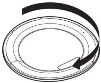
natural_image
Abstract circular diagram with concentric rings and a curved arrow, no text or symbols presentnatural_image
Technical diagram of a curved mechanical component with directional arrows indicating motion or force (no text or symbols)natural_image
Technical line drawing of a mechanical component with a curved internal structure and mounting brackets (no text or symbols)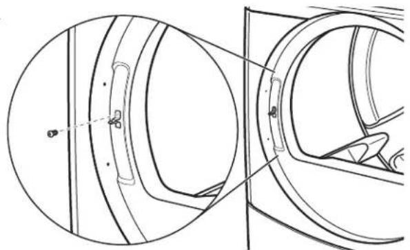
natural_image
Technical line drawing of a mechanical component with cross-sectional view (no text or symbols)natural_image
Technical line drawing of a circular mechanical component with mounting holes and internal features (no text or symbols)TOTAL = 225 programmes
Maytag Commercial Laundry Service Department
2000 M-63 North
Benton Harbor, Michigan 49085 USA
natural_image
Top-down schematic of a mechanical component or housing (no text or symbols)natural_image
Two pipe elbow diagrams labeled A and B, showing different structural layouts (no text or symbols present)natural_image
Technical line drawing of a circular mechanical component with mounting holes and internal features (no text or symbols)natural_image
Technical line drawing of a mechanical component with an arrow indicating direction (no text or symbols)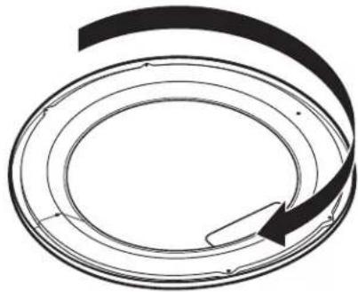
natural_image
Abstract circular diagram with concentric rings and a curved arrow, no text or symbols presentInvierta la bisagra
natural_image
Technical diagram of a mechanical component with directional arrows indicating motion or force (no text or symbols)natural_image
Technical line drawing of a mechanical component with a circular housing and internal structure (no text or symbols)
natural_image
Technical line drawing of a mechanical component with circular and rectangular views (no text or symbols)natural_image
Technical line drawing of a circular mechanical component with mounting holes and internal features (no text or symbols)natural_image
Top-down schematic of a vehicle or vehicle chassis with no text, numbers, or symbols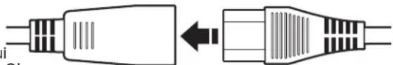
natural_image
Diagram showing two types of plug connectors, one with internal lines and the other with striped ends, connected by an arrow indicating transformation (no text or symbols present)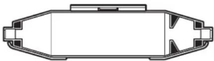
natural_image
Top-down schematic of a vehicle or container with no text, numbers, or symbolsAVVERTENZA

natural_image
Two pipe elbow diagrams labeled A and B, showing different structural sections (no text or symbols beyond labels)natural_image
Technical line drawing of a circular mechanical component with mounting holes and internal features (no text or symbols)natural_image
Technical line drawing of a mechanical component with a circular housing and internal components (no text or symbols)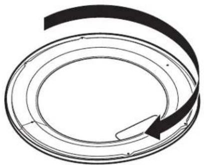
natural_image
Diagram of a circular mechanical or electrical component with an arrow indicating rotation (no text or symbols)natural_image
Technical diagram of a mechanical component with three upward arrows indicating motion or force directions (no text or symbols present)natural_image
Technical line drawing of a mechanical component with a circular housing and internal structure, showing a directional arrow (no text or symbols)