
GZHA 4150 X - Car radio Ground Zero - Free user manual and instructions
Find the device manual for free GZHA 4150 X Ground Zero in PDF.
| Product type | 4-channel amplifier |
| Brand | Ground Zero |
| Model | GZHA 4150 X |
| Dimensions (L x H x D) | 305 x 62 x 400 mm |
| Weight | Approx. 3.5 kg |
| Power supply | 12 V DC (vehicle battery), fuses 2 x 40 A |
| RMS Power @ 4 Ω (1% THD+N) | 4 x 130 W |
| RMS Power @ 2 Ω (1% THD+N) | 4 x 200 W |
| RMS Power @ 4 Ω bridged (1% THD+N) | 2 x 400 W |
| Frequency response | 10 Hz - 36 kHz (±1 dB) |
| Signal-to-noise ratio | > 70 dB |
| Total harmonic distortion (THD) | < 0.10 % |
| Low-pass filter (LPF) | 30 Hz - 250 Hz (channels 3 & 4) |
| High-pass filter (HPF) | 40 Hz - 3 kHz (channels 1 & 2) / 5 Hz - 250 Hz (channels 3 & 4) |
| Subsonic filter | 5 Hz - 250 Hz (channels 3 & 4) |
| Bass boost | 0 to +12 dB |
| Phase shift | 0° - 180° (channels 3 & 4) |
| Input sensitivity | 200 mV - 9 V |
| Input impedance | 4 Ω - 8 Ω (speakers) |
| Outputs | RCA inputs, full-range RCA output (for additional amplifier), high-level speaker input |
| Protections | Short circuit, overheating, overload, LED protection |
| Materials | Aluminum (heat sink), SMD components |
| Installation | In-vehicle mounting, requires power cable min. 16 mm², ground cable min. 10 mm² |
| Warranty | In accordance with legal rights, return in original packaging with receipt |
Frequently Asked Questions - GZHA 4150 X Ground Zero
User questions about GZHA 4150 X Ground Zero
0 question about this device. Answer the ones you know or ask your own.
Ask a new question about this device
Download the instructions for your Car radio in PDF format for free! Find your manual GZHA 4150 X - Ground Zero and take your electronic device back in hand. On this page are published all the documents necessary for the use of your device. GZHA 4150 X by Ground Zero.
USER MANUAL GZHA 4150 X Ground Zero
Limited warranty - defective products must be returned in original packaging - please add a copy of the original purchasing invoice showing the purchasing date and a detailed description of the failure. Failure caused by overload, misuse or by using the product for competition purpose are not covered by the warranty.
wwwground-zero-audio.com
We reserve the right to make needed change or improvement to the product without informing customer about this in advance.
Thank you for selecting a Ground Zero amplifier.
We are providing a helpful hints list which should keep you from experiencing
unnecessaryshutdown.
Have fun with this high quality Hydrogen product.
Features
- 4 Ohm / 2 Ohm stable stereo
1 Ohm stable stereo (GZHA 2350XII / Channel 5 of GZHA 5125XII)
P.W.M. Mosfet power supply
SMD Technology
Power & Protection indicator
Variable 12dB Bass Boost (GZHA 2350XII)
Variable high pass filter
Variable low pass filter
Variable subsonic filter
Variable phase shift 0 ~ 180° - Switchable phase shift 0^ / 180^ (GZHA 5125XII)
Adjustable input sensitivity
Soft delayed remote turn-on - RCA outputs (GZHA 4150XII)
Remote control
Thermal/Short/Overload protection
Hydrogen amplifiers
Due to their state-of-the-art technology and high efficiency, those amplifiers help your system to provide an impressive sound experience. The modern circuit technology of the power supply and the signal processing allows achieving maximum performance levels from the provided power.
Tools and materials you need
- Screwdriver
Electric drill. 3 mm/0.12" carbide drill bil
Mounting screws
Power wire min. 16 mm² / 5 AWG
Ground wire min. 16 mm² / 5 AWG - Speaker wire min. 2 x 1,5 mm² / 15 AWG
Please note!
- As a precaution it is advisable to disconnect the vehicle's battery before making connection to the +12 Volts supply wiring (see owner's manual of your car for further information).
- Please use great caution drilling your trunk. Your gas tank and brake lines can be damaged by puncturing with your drill bit - this could cause damage or failure of your cars operating systems.
- Never pass wires over sharp angles. It is recommended to buffer the power supply of the amplifier with an capacitor min. 1 Farad to guarantee a stable operation voltage.
WARNING!
High powered audio systems in a vehicle are capable of gonarizing "Live Concert" levels of sound pressure. Continued exposure to excessively high volume sound levels may cause hearing loss or damage. Also, operation of a motor vehicle while listening to audio equipment at high volume levels may impair your ability to hear external sounds such as; horns, warning signals, or emergency vehicles, thus constituting a potential traffic hazard. In the interest of safety, Consumer Electronics recommends listening at lower volume levels while driving.
Planning your system
Before beginning the installation, consider the following:
a. If you plan to expand your system by adding other components sometime in the future, ensure adequate space is left, and cooling requirements are met.
b. If your radio source is equipped with pre-amp outputs, it is possible to utilize them to drive the amplifier and connecting (amplifier) to the 2 near speakers.
Mounting your amplifier
a. Select a suitable location that is convenient for mounting, is accessible for wiring and has ample room for air circulation and cooling.
b. Use the amplifier as a template to mark the mounting holes, remove the amplifier
Warning
Choose a mounting position where all oscillos wires are protected from being damaged by sharp edges, heat or other conditions. +12Volt DC electrical connections must be fused on the battery side. Make sure your radio and all other devices will be turned off while connection your system.
If you need to replace the power fuse, replace it only with a fuse identical to that supplied with the system. Using a fuse of different type or rating may result in damage to this system which isn't covered by the warranty.
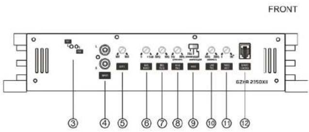
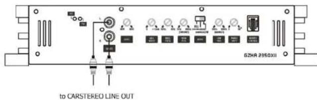
Controls and functions - GZHA 2350XII
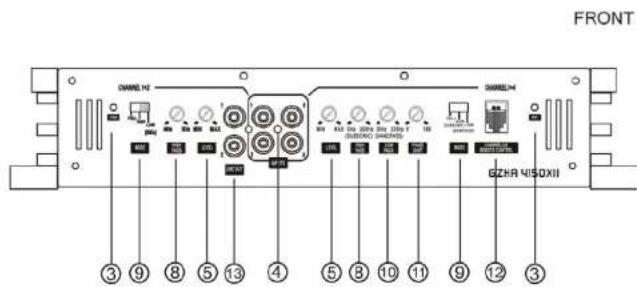
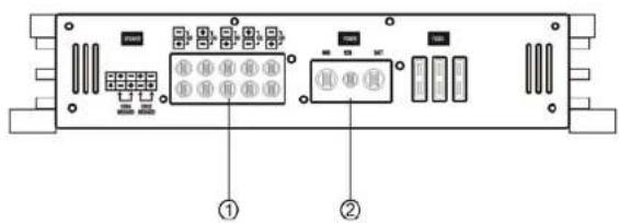
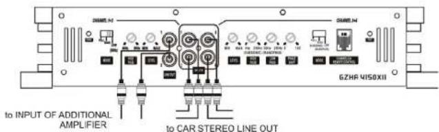
Controls and functions - GZHA 4150XII
5
6
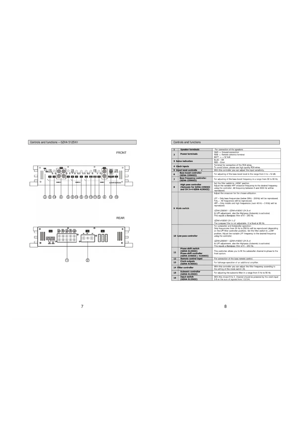
Controls and functions - GZHA 5125XII
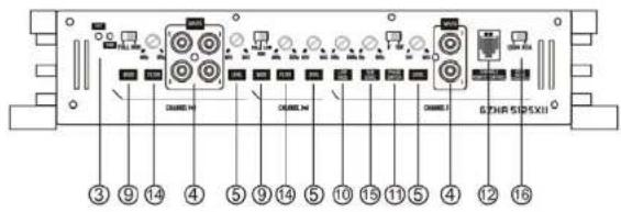
FRONT
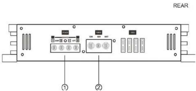
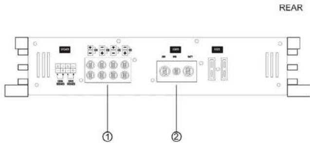
REAR
Controls and functions
| 1 | Speaker terminals | For connection of the speakers |
| 2 | Power terminals | GND -> Ground connection.REM -> Remote antenna terminalBATT -> + 12 Volt |
| 3 | Status indication | BLUE = OARED = Error |
| 4 | Pinch Inputs | Terminal for connection of the PCA wires.To avoid failure, please use high quality PCA wires. |
| 5 | Input level controller r | With this controller you can adjust the input sensitivity. |
| 6 | Base boost controller(GZHA 2350XII) | For adjusting of the base boost level in the range from 0 to -12 dB. |
| 7 | Base frequency controller(GZHA 2350XII) | For adjusting of the base boost frequency in a range from 30 to 80 Hz. |
| 8 | High pass controller(Subsonic for GZHA 2350XIIand CH 3+4 GZHA 4150XII) | Set the filter switch to "HIGH" position.Adjust the variable HPF crossover frequency to the desired frequency using the controller. All frequency between 5 and 3000 Hz will be reproduced. |
| 9 | Mode switch | Adjust the crossover for the chosen utilization.LPF - Only base frequencies (below 30Hz - 250Hz) will be reproduced.FULL - All frequencies will be reproduced.HPF - Only middle and high frequencies (over 40 Hz - 3 KHz) will be reproduced.GZHA 2350XII / GZHA 4150XII CH 3+4.At LPF adjustment, also the Highpass (Subsonic) is activated.This equals a Bandpass filler of 5 - 250 Hz.GZHA 4150XII CH 1+2The Lowpass filter is not adjustable. It is fixed at 80 Hz. |
| 10 | Low pass controller | For subwoofer and Kickrooster operation -Only frequencies from 30 Hz to 250 Hz will be reproduced (depending on the LPF filler controller position). Set the filter switch to LOW"position. Adjust the variable LPF frequency to the desired frequency using the controller.GZHA 2350XII / GZHA 4150XII CH 3+4.At LPF adjustment, also the Highpass (Subsonic) is activated.This equals a Bandpass filler of 5 - 250 Hz. |
| 11 | Phase shift switch(GZHA 5125XII)Phase shift controller(GZHA 2350XII / 4150XII) | This controller allows you to fit the subwoofer channel in-phase to the front system. |
| 12 | Remote control input | For connection of the bass remote control. |
| 13 | Pinch outputs(GZHA 4150XII) | For fullrange operation of an additional amplifier. |
| 14 | Filter controller | With this controller you can adjust the filter frequency according to the setting of the mode switch.(9). |
| 15 | Subsonic controller(GZHA 5125XII) | For adjusting the subsonic filter in a range from 5 Hz to 50 Hz. |
| 16 | Input switch(GZHA 5125XII) | With this choice if the S Channel should be powered by the cinch input 5/8 or the sum of signals from 1/2/3/4. |
Turning on the amplifier
The amplifier automatically turns on a few seconds after you turn on your radio.
Note: Your amplifier temporarily shuts down if it gets too hot, then restarts automatically once it cools
(A1 about 80^ / 176^ F1.
Adjusting the audio level
LEVEL(MinMax):Turn fully caunter clockwise to MIN position
2. Turn the auto sound system's volume control to about two-third of its full range.
3. Adjust LEVEL to a comfortable listening level.
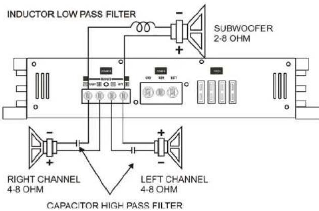
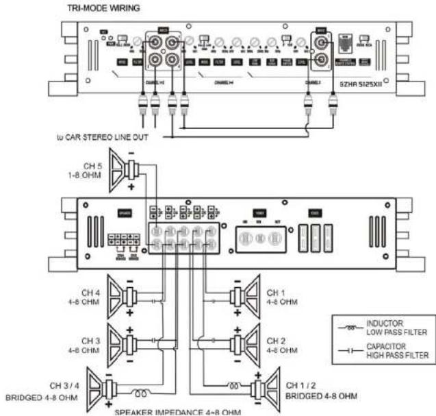
Connecting the speaker for trimode operation - notes
TRI MCOE operation output allows a subwoofer to be operated in mono mode while the main speakers are playing in stereo. Leave this crossover switch on "Full" position.
Use 100 volt, non-polar capacitors for a high pass crossover to filter out low frequencies and Air-core or Fortri- orcells with a minimum diameter of 1mm / 0.030^4 for the lowpass crossover to filter out high frequencies.
The capacitor and inductor values as written in the below table. The front and rear channels of this amplifier get the capability. Only the rear left and right channels are shown on the following pictures.
Values for 6dB passive crossover
| Frequency Inductor Capacitor | |
| 80 Hz 7,5 mH 470 uF | |
| 100 Hz 6,5 mH 330 uF | |
| 120 Hz 5,5 mH 370 uF | |
| 150 Hz 4 mH 220 uF | |
Connecting the speaker - GZHA 2350XII
STEREO WIRING
(A)STEREO MODE
(B) MONO MODE
Trimode operation-GZHA 2350X11
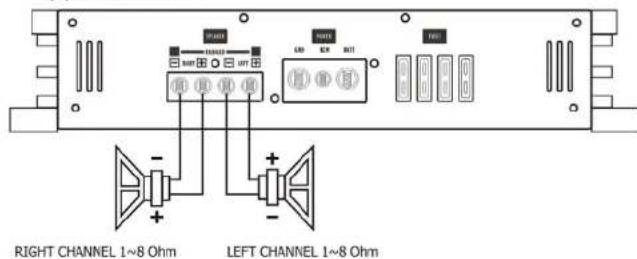
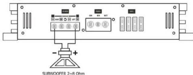
Connecting the speaker - GZHA 4150XII
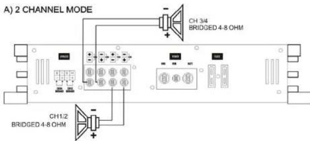
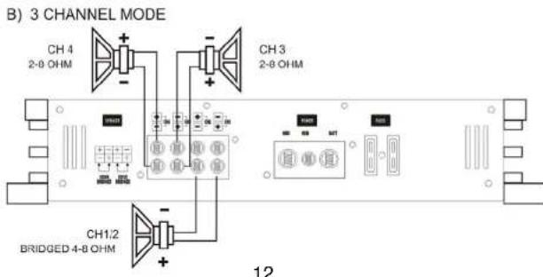
Trimode operation-GZHA 4150XII
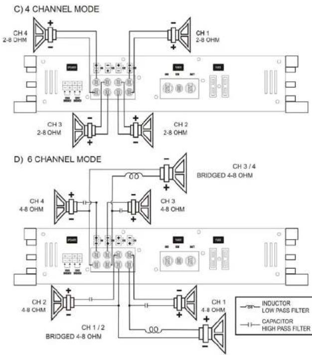
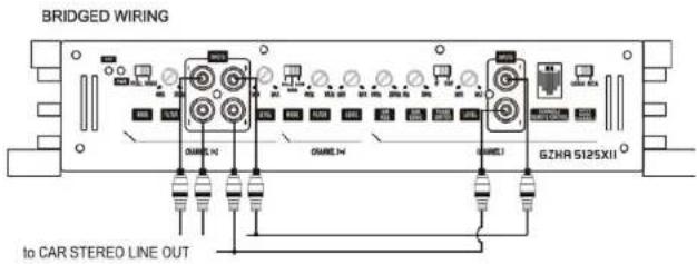
Connecting the speaker - GZHA 5125XII
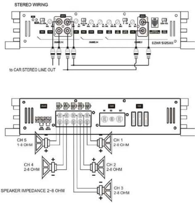
Connecting the speaker - GZHA 5125XII (Bridged)
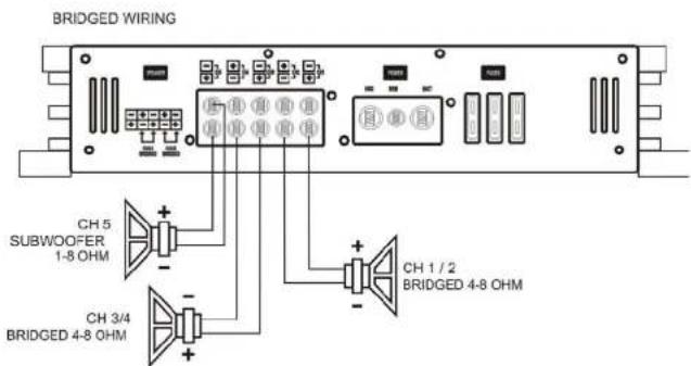
SPEAKER IMPEDANCE 4-8 OHM
Trimode operation - GZHA 5125XII
Specifications
| Model GZHA 2350XII GZHA 4150XII | GZHA S125XII | |||
| Channel 1-4 Channel 5 | ||||
| RMS Power @ 4 ΩCEA Standard CEA-2006-A | 2 x 250W (1% THD+);N2x 325W (10% THD+);N2 | 4 x 150W (1% THD+);N24 x 160W (10% THD+);N2 | 4 x 100W (1% THD-);N24 x 120W (10% THD+);N2 | 1 x 270W (1% THD+);N1x 380W (10% THD-);N2 |
| RMS Power @ 2 ΩCEA Standard CEA-2006-A | 2 x 470W (1% THD+);N2x 575W (10% THD+);N2 | 4 x 200W (1% THD+);N24 x 250W (10% THD+);N2 | 4 x 150W (1% THD-);N24 x 200W (10% THD+);N2 | 1 x 430W (1% THD+);N1x 620W (10% THD-);N2 |
| RMS Power @ 1 ΩCEA Standard CEA-2006-A | 2 x 740W (1% THD+);N2x 900W (10% THD-);N2 | ... | ... | 1 x 800W (1% THD-);N1x 900W (10% THD-);N2 |
| RMS Power @ 4Ω bridgedCEA Standard CEA-2006-A | 1 x 940W (1% THD+);N1x 1140W (10% THD+);N2 | 2 x 400W (1% THD+);N22 x 500W (10% THD-);N2 | 2 x 300W (1% THD-);N22 x 400W (10% THD-);N2 | ... |
| RMS Power @ 2Ω bridgedCEA Standard CEA-2006-A | 1 x 1480W (1% THD+);N1x 1800W (10% THD+);N2 | ... | ... | |
| Damping factor | > 200 > 130 > 20 > 70 | |||
| Signal to noise Ratio | > 70 dB > 70 dB > 70 dB | |||
| Lowpass | 30 Hz - 250 Hz | 80 Hz( Channel 1 & 2)30 Hz - 250 Hz( Channel 3 & 4 ) | 40 Hz - 3 KHz( Channel 3 & 4 ) | 30 Hz - 250 Hz |
| Highpass | 5 Hz - 500 Hz | 40 Hz - 5 KHz( Channel 1 & 2)5 Hz - 250 Hz( Channel 3 & 4 ) | 40 Hz - 3 KHz( Channel 1 - 4 ) | ... |
| Bandpass | 5 Hz - 250 Hz | 5 Hz - 250 Hz( Channel 3 & 4 ) | ... 5 Hz - 250 Hz | ... |
| Subsonic filter | 5 Hz - 500 Hz | 5 Hz - 250 Hz( Channel 3 & 4 ) | ... 5 Hz - 50 Hz | ... |
| Bass boost | 0 ~ +12 dB ... ... | |||
| Bass boost frequency | 30 Hz - 80 Hz ... ... | |||
| Phase shift | 0 ~ 180° | 0 ~ 180°( Channel 3 & 4 ) | ... 0 ~ 180° | |
| Frequency response | 10 Hz - 36 KHz( ± 1 dB ) | 10 Hz - 36 KHz( ± 1 dB ) | 10 Hz - 22 KHz( ± 1 dB ) | 10 Hz - 250 Hz( ± 1 dB ) |
| Efficiency @ 4 Ω | - 80 % - 80 % - 80 % | |||
| Input sensitivity | 200 mV - 8 V( ± 5%) | 200 mV - 9 V( ± 5%) | 200 mV - 9 V( ± 5%) | |
| Channel separation | 50 dB | 50 dB | 50 dB | |
| THD | < 0.10 % | < 0.10 % | < 0.10 % | |
| Bass remote | √At lowpass operation | √( Channel 3 & 4 ) | ... | √At lowpass operation |
| Fuse | 4 x 40A | 2 x 40A | 3 x 40A | |
| Dimensions W x H x L mm | 305 x 62 x 400 | 305 x 62 x 400 | 305 x 62 x 500 | |
| Dimensions W x H x L Inch | 12 x 2.44 x 15.75 | 12 x 2.44 x 15.75 | 12 x 2.44 x 19.68° | |
Trouble shooting guide
| Symptoms | Check Points | Cure |
| No sound | Is the POWER LED illuminated? | Check fuses in amplifier. Be sure remote lead is connected. Check signal leads. Check again control. Check timer/dock volume level. |
| Is the diagnostic LED illuminated? | Check for speaker short or amplifier overheating | |
| Amp not switching on | No power to the amplifier | Check power wire or connections |
| No power to remote wire with receiver on | Check connections to radio | |
| No sound in one channel | Check speaker loads | Inspect for short circuit or an open connection |
| Check audio leads | Reverse left and right RCA inputs to determine if it is occurring before the amp | |
| Amp turning off at medium / high volume | Check speaker load impedance | Be sure proper speaker load impedance recommendations are observed (If you use an ohm meter to check speaker resistance, please remember that DC resistance and AC impedance may not be the same.) |
| Protection LED is on | Temperature shut down Turn radio | Volume down |
| Speaker wires short | Separate speaker wires and insulate |
Limited warranty - defective products must be returned in original packaging - please add a copy of the original purchasing invoice showing the purchasing date and a detailed description of the failure. Failure caused by overload, misuse or by using the product for competition purpose are not covered by the warranty.
wwwground-zero-audio.com
We reserve the right to make needed change or improvement to the product without informing customer about this in advance.
Limited warranty - defective products must be returned in original packaging - please add a copy of the original purchasing invoice showing the purchasing date and a detailed description of the failure. Failure caused by overload, misuse or by using the product for competition purpose are not covered by the warranty.
www.ground-zero-audio.com
We reserve the right to make needed change or improvement to the product without informing customer about this in advance.
www.ground-zero-audio.NL
We reserve the right to make needed changes or improvement to the product without informing customer about this in advance.

GROUND ZERO
MOBILE ENTERTAINMENT
Vahvistimen
Käytöohje
HYDROGEN
GZHA 2350XII
GZHA 4150XII
GZHA 5125XII

GROUND ZERO
MOBILE ENTERTAINMENT
Limited warranty - defective products must be returned in original packaging - please add a copy of the original purchasing invoice showing the purchasing date and a detailed description of the failure. Failure caused by overload, misuse or by using the product for competition purpose are not covered by the warranty.
www.ground-zero-audio.com
We reserve the right to make needed change or improvement to the product without informing customer about this in advance.


- Features
- Hydrogen amplifiers
- Tools and materials you need
- Please note!
- WARNING!
- Planning your system
- Mounting your amplifier
- Warning
- Turning on the amplifier
- Adjusting the audio level
- Connecting the speaker for trimode operation - notes
- Values for 6dB passive crossover
- Connecting the speaker - GZHA 2350XII
- GROUND ZERO
- Vahvistimen
- HYDROGEN
Brand : Ground Zero
Model : GZHA 4150 X
Category : Car radio