
PDP615EX - TV PIONEER - Free user manual and instructions
Find the device manual for free PDP615EX PIONEER in PDF.

| Product type | Plasma display monitor |
| Brand | Pioneer |
| Model | PDP-615EX |
| Screen size (diagonal) | 61 inches (155 cm) |
| Native resolution | 1365 x 768 pixels |
| Aspect ratio | 16:9 |
| Dimensions (W x H x D) | 1502 x 912 x 126 mm |
| Power supply | 220-240 V AC, 50/60 Hz |
| Power consumption (typical) | 540 W |
| Power consumption (standby) | 1.8 W |
| Audio output (built-in speakers) | 9 W + 9 W (6 Ω) |
| Video inputs | PC1 (D-Sub 15), PC2/COMPONENT2 (BNC 5), HDMI, COMPONENT1 (RCA), VIDEO1 (BNC), VIDEO2 (RCA), VIDEO3 (S-Video) |
| Audio inputs | 3 x RCA stereo (selectable), HDMI audio |
| Serial connectivity | RS-232C (D-Sub 9-pin) |
| Main functions | Digital zoom, wide screen (multiple formats), side-by-side and picture-in-picture mode, gamma correction, noise reduction, screen saver, anti-burn-in functions |
| Operating temperature | 0°C to 40°C |
| Cleaning | Supplied soft dry cloth; do not use alcohol or solvents; vacuum ventilation grilles monthly |
| Safety | Do not expose to rain or moisture; do not open the cabinet (high voltage); easily accessible plug; install with sufficient space for ventilation |
| Recommended optional accessories | Tabletop stand PDK-1014, wall mount PDK-WM03 |
| Repairability | Have all repairs done by a qualified technician; opening the cabinet by unqualified personnel voids warranty |
| Package contents | Monitor, power cord, remote control with batteries, manual, warranty, metal fixings (x2), ferrite cores (x2), cable ties (x5), cleaning cloth |
Frequently Asked Questions - PDP615EX PIONEER
User questions about PDP615EX PIONEER
0 question about this device. Answer the ones you know or ask your own.
Ask a new question about this device
Download the instructions for your TV in PDF format for free! Find your manual PDP615EX - PIONEER and take your electronic device back in hand. On this page are published all the documents necessary for the use of your device. PDP615EX by PIONEER.
USER MANUAL PDP615EX PIONEER
Operating Instructions
Mode d'emploi
Bedienungsanleitung
Operating Instructions
Thank you very much for purchasing this PIONEER product. Before using your Plasma Display, please carefully read the "Important Information" and these "Operating Instructions" so you will know how to operate the Plasma Display properly. Keep this manual in a safe place. You will find it useful in the future.
Notes on Installation Work:
This product is marketed assuming that it is installed by qualified personnel with enough skill and competence. Always have an installation specialist or your dealer install and set up the product. PIONEER cannot assume liabilities for damage caused by mistake in installation or mouting, misuse, modification or a natural disaster.
Note for Dealers:
After installation, be sure to deliver this manual to the customer and explain to the customer how to handle the product.
Precautions
Please read this manual carefully before using your plasma monitor and keep the manual handy for future reference.
CAUTION

RISK OF ELECTRIC SHOCK DO NOT OPEN

CAUTION: TO REDUCE THE RISK OF ELECTRIC SHOCK, DO NOT REMOVE COVER. NO USER-SERVICEABLE PARTS INSIDE. REFER SERVICING TO QUALIFIED SERVICE PERSONNEL.

This symbol warns the user that uninsulated voltage within the unit may have sufficient magnitude to cause electric shock. Therefore, it is dangerous to make any kind of contact with any part inside of this unit.

This symbol alerts the user that important literature concerning the operation and maintenance of this unit has been included. Therefore, it should be read carefully in order to avoid any problems.
WARNING
TO PREVENT FIRE OR SHOCK HAZARDS, DON NOT EXPOSE THIS UNIT TO RAIN OR MOISTURE. ALSO DO NOT USE THIS UNIT'S POLARIZED PLUG WITH AN EXTENSION CORD RECEPTACLE OR OTHER OUTLETS, UNLESS THE PRONGS CAN BE FULLY INSERTED. REFRAIN FROM OPENING THE CABINET AS THERE ARE HIGH-VOLTAGE COMPONENTS INSIDE. REFER SERVICING TO QUALIFIED SERVICE PERSONNEL.
Warnings and Safety Precaution
This plasma monitor is designed and manufactured to provide long, trouble-free service. No maintenance other than cleaning is required. Please see the section "Plasma monitor cleaning procedure" on the next page.
The plasma display panel consists of fine picture elements (cells) with more than 99.99 percent active cells. There may be some cells that do not produce light or remain lit.
For operating safety and to avoid damage to the unit, read carefully and observe the following instructions. To avoid shock and fire hazards:
- Provide adequate space for ventilation to avoid internal heat build-up. Do not cover rear vents or install the unit in a closed cabinet or shelves.
If you install the unit in an enclosure, make sure there is adequate space at the top of the unit to allow hot air to rise and escape. If the monitor becomes too hot, the overheat protector will be activated and the monitor will be turned off. If this happens, turn off the power to the monitor and unplug the power cord. If the room where the monitor is installed is particularly hot, move the monitor to a cooler location, and wait for 60 minutes to cool the monitor. If the problem persists, contact your dealer for service. - Do not use this unit's polarized plug with extension cords or outlets unless the prongs can be completely inserted.
- Do not expose the unit to water or moisture.
- Avoid damage to the power cord, and do not attempt to modify the power cord.
- Unplug the power cord during electrical storms or if the unit will not be used over a long period.
- Do not open the cabinet which has potentially dangerous high voltage components inside. If the unit is damaged in this way the warranty will be void. Moreover, there is a serious risk of electric shock.
- Do not attempt to service or repair the unit. The manufacturer is not liable for any bodily harm or damage caused if unqualified persons attempt service or open the back cover. Refer all service to authorized Service Centers.
NOTE:
When you connect a computer to this monitor, use an RGB cable including the ferrite core on both ends of the cable.
If you do not do this, this monitor will not conform to mandatory CE or C-Tick standards.
Attaching the ferrite cores:
Set the ferrite cores on both ends of the power cable (supplied).
Close the lid tightly until the clamps click.

Power cable (supplied)
To avoid damage and prolong operating life:
- Use only with 220-240 V 50 / 60Hz AC power supply. Continued operation at line voltages greater than 220-240 Volts AC will shorten the life of the unit, and might even cause a fire hazard.
- Handle the unit carefully when installing it and do not drop.
- Set the unit away from heat, excessive dust, and direct sunlight.
- Protect the inside of the unit from liquids and small metal objects. In case of accident, unplug the power cord and have it serviced by an authorized Service Center.
- Do not hit or scratch the panel surface as this causes flaws on the surface of the screen.
- For correct installation and mounting it is strongly recommended to use a trained, authorized dealer.
- As is the case with any phosphor-based display (like a CRT monitor, for example) light output will gradually decrease over the life of a Plasma Display Panel.
- To avoid sulfurization it is strongly recommended not to place the unit in a dressing room in a public bath or hot spring bath.
- Do not use in a moving vehicle, as the unit could drop or topple over and cause injuries.
- Do not place the unit on its side, upside-down or with the screen facing up or down, to avoid combustion or electric shock.
Plasma monitor cleaning procedure:
- Use a wiping cloth (attached) or a soft dry cloth to clean the front panel and bezel area. Never use solvents such as alcohol or thinner to clean these surfaces.
- Clean plasma ventilation areas with a vacuum cleaner with a soft brush nozzle attachment.
- To ensure proper ventilation, cleaning of the ventilation areas must be carried out monthly. More frequent cleaning may be necessary depending on the environment in which the plasma monitor is installed.
Recommendations to avoid or minimize phosphor burn-in: Like all phosphor-based display devices and all other gas plasma displays, plasma monitors can be susceptible to phosphor burn under certain circumstances. Certain operating conditions, such as the continuous display of a static image over a prolonged period of time, can result in phosphor burn if proper precautions are not taken. To protect your investment in this plasma monitor, please adhere to the following guidelines and recommendations for minimizing the occurrence of image burn:
- Always enable and use your computer's screen saver function during use with a computer input source.
- Display a moving image whenever possible.
- Change the position of the menu display from time to time.
- Always power down the monitor when you are finished using it.
If the plasma monitor is in long term use or continuous operation take the following measures to reduce the likelihood of phosphor burn:
- Lower the Brightness and Contrast levels as much as possible without impairing image readability.
- Display an image with many colors and color gradations (i.e. photographic or photo-realistic images).
- Create image content with minimal contrast between light and dark areas, for example white characters on black backgrounds. Use complementary or pastel color whenever possible.
-
Avoid displaying images with few colors and distinct, sharply defined borders between colors.
-
Note: Burn-in is not covered by the warranty.
Contact your dealer for other recommended procedures that will best suit your particular application needs.
CAUTION:
WHEN POSITIONING THIS EQUIPMENTENSURE THAT THE MAINS PLUG AND SOCKET IS EASILY ACCESSIBLE.
This product complies with the Low Voltage Directive (73/23/EEC, amended by 93/68/EEC), EMC Directives (89/336/EEC, amended by 92/31/EEC and 93/68/EEC).
Caution
This model is for use with the following optional accessories. Use with other optional accessories is capable of resulting in instability causing possible injury.
Table top stand: PDK-1014
Wall mount unit: PDK-WM03
Installation 2
Ventilation Requirements for enclosure mounting 2
How to use the safety metal fittings and the screws for safety metal fittings. 2
Cable Management 3
How to use the remote control. 3 Battery Installation and Replacement 3
Operating Range 3
Handling the remote control 3
Part Names and Function 4
Front View 4
Rear View/ Terminal Board 5
Remote Control 6
Basic Operations 7
POWER 7
To turn the unit ON and OFF: 7
VOLUME 7
To adjust the sound volume: 7
MUTING 7
To mute the sound: 7
DISPLAY 7
To check the settings: 7
DIGITAL ZOOM 7
OFF TIMER 7
To set the off timer: 7
To check the remaining time: 7
To cancel the off timer: 7
WIDE Operations 8
SCREEN SIZE Operation (manual) 8
When viewing videos or digital video discs 8
SCREEN SIZE Operation with Computer Signals 9
SPLIT SCREEN Operations 10
Showing a couple of pictures on the screen at the same time 10
Operations in the Side-by-side mode 10
Operations in the Picture-in-picture mode 11
Selecting the input signals to be displayed 11
Zooming up pictures 11
Adjusting the OSD controls 11
OSD (On Screen Display) Controls 12
Menu Operations 12
Setting the language for the menus. 12
Menu Tree 13
Picture Settings Menu. 15
Storing picture settings. 15
Adjusting the picture 15
Reducing noise in the picture 15
Setting the color temperature 16
Adjusting the color to the desired level 16
Changing the Gamma Curve 16
Making the Low Tone adjustments. 16
Adjusting the pedestal level (black level) 17
Adjusting the colors 17
Setting the picture to suit the movie 17
Setting the picture modes according to the brightness of the room 17
SOUND Settings Menu 18
Adjusting the treble, bass and left/right balance and audio input select. 18
Setting the allocation of the audio connectors 18
SCREEN Settings Menu 18
Adjusting the Position, Size, PHASE, CLOCK 18
SET UP Settings Menu 19
Setting the PC2/COMPONENT2 connectors 19
Setting the PC1 connector 19
Setting high definition images to the suitable screen size ... 19
Setting a computer image to the correct RGB select screen 19
Setting the black level for HDMI signal 20
Setting the video signal format 20
Setting the background color when no signal is being input 20
Setting the gray level for the SIDE MASK. 21
Setting the screen size for S1/S2 video input 21
Turning on/off the information display 21
Setting the position of the menu 21
Resetting to the default values 21
Function Settings Menu 22
Setting the power management for computer images .... 22
STANDBY/ON indicator 22
Setting the Input Skip 22
Erasing the sub screen image when there is no input signal. 22
Displaying the entire image during DIGITAL ZOOM operations 23
Displaying still images in the sub screen 23
Reducing burn-in of the screen 23
Signal Information Menu 25
Checking the frequencies, polarities of input signals, and resolution 25
Pin Assignments 26
i D-Sub 15-pin connector (Analog) 26
Table of Signals Supported 27
Supported resolution 27
Troubleshooting 29
Specifications 30
Contents of the Package
Plasma monitor
Power cord
Remote control with two AAA Batteries
□ Manual
Warranty
Safety metal fittings (2pcs)*
Ferrite cores (2pcs)
Cable clamps (5pcs)
Wiping cloth
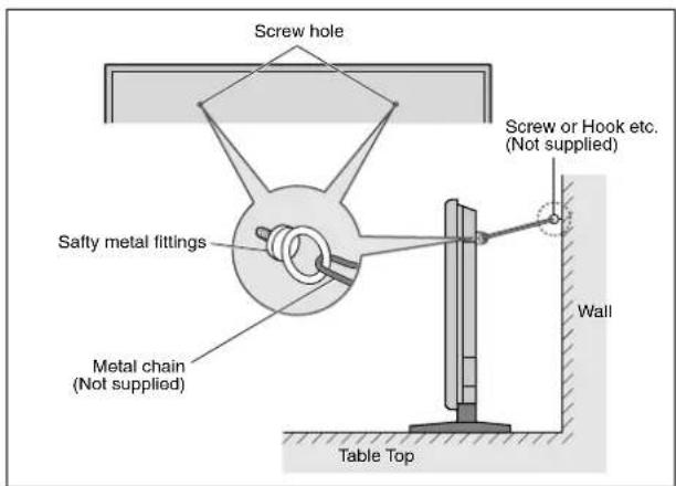
- These are fittings for fastening the unit to a wall to prevent tipping due to external shock when using the stand (optional). Fasten the safety fittings to the holes in the back of the monitor using the safety fitting mount screws (see page 2).
Options
- Wall mount unit
- Stand
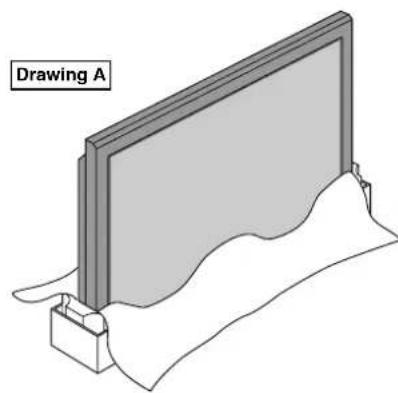
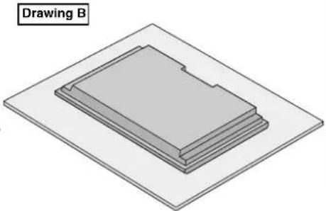
You can attach your optional mounts or stand to the plasma monitor in one of the following two ways:
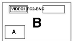
- While it is upright. (See Drawing A)
- As it is laid down with the screen face down (See Drawing B). Lay the protective sheet, which was wrapped around the monitor when it was packaged, beneath the screen surface so as not to scratch the screen face.
-
Do not touch or hold the screen face when carrying the unit.
-
This device cannot be installed on its own. Be sure to use a stand or original mounting unit. (Wall mount unit, Stand, etc.)
- See page 1.
- For correct installation and mounting it is strongly recommended to use a trained, authorized dealer.
Failure to follow correct mounting procedures could result in damage to the equipment or injury to the installer.
Product warranty does not cover damage caused by improper installation.
- Use only the mounting kit or stand provided by manufacturer and listed under Options.
When installing or carrying, use the handles attached to the upper back of the display.
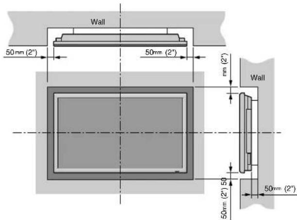
Ventilation Requirements for enclosure mounting
To allow heat to disperse, leave space between surrounding objects as shown on the diagram below when installing.
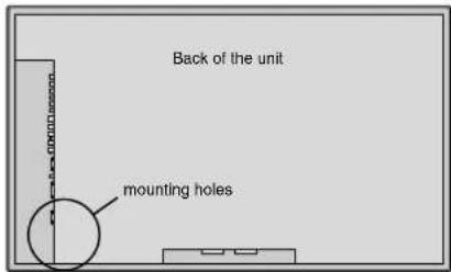
How to use the safety metal fittings and the screws for safety metal fittings
These are fittings for fastening the unit to a wall to prevent tipping due to external shock when using the stand (optional). Fasten the safety fittings to the holes in the back of the monitor using the safety fitting mount screws.
Cable Management
Using the cable clamps provided with the plasma display, bundle at the back of the unit the signal and audio cables connected to the display.

To attach
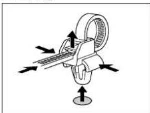
To detach
How to use the remote control Battery Installation and Replacement
Insert the 2 "AAA" batteries, making sure to set them in with the proper polarity.
- Press and open the cover.
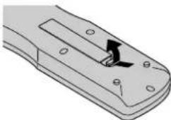
- Align the batteries according to the (+) and (-) indication inside the case.

- Replace the cover.

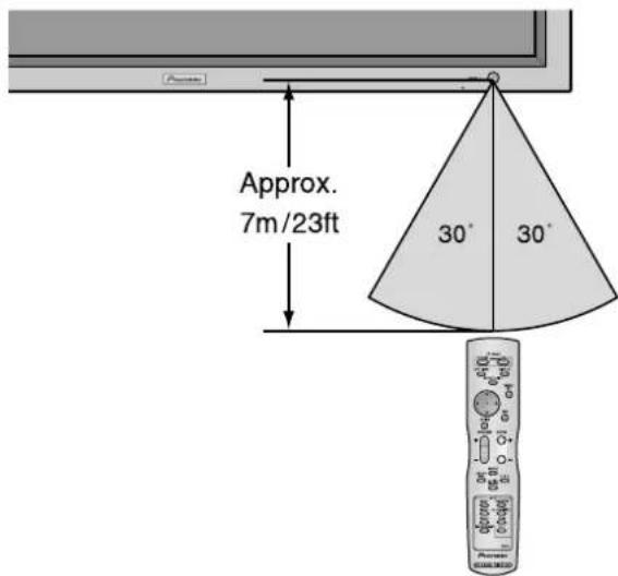
Operating Range
- Use the remote control within a distance of about 7m/ 23ft. from the front of the monitor's remote control sensor and at horizontal and vertical angles of up to approximately 30^
- The remote control operation may not function if the monitor's remote control sensor is exposed to direct sunlight or strong artificial light, or if there is an obstacle between the sensor and the remote control.
Handling the remote control
- Do not drop or mishandle the remote control.
- Do not get the remote control wet. If the remote control gets wet, wipe it dry immediately.
- Avoid heat and humidity.
- When not using the remote control for a long period, remove the batteries.
- Do not use new and old batteries together, or use different types together.
- Do not take apart the batteries, heat them, or throw them into a fire.
- When disposing of used batteries, please comply with governmental regulations or environmental public instruction's rules that apply in your country/area.
Part Names and Function
Front View
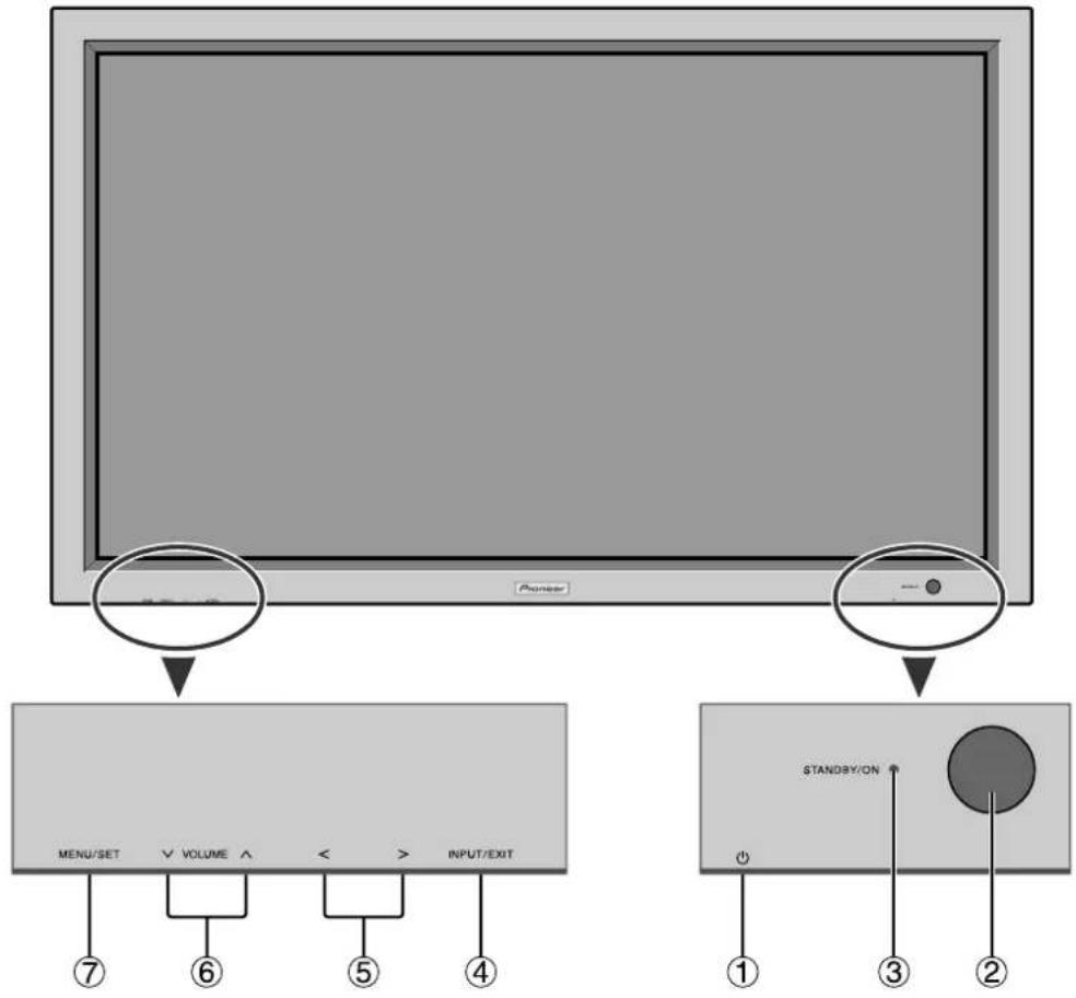
①Power( )
Turns the monitor's power on and off.
② Remote sensor window
Receives the signals from the remote control.
③STANDBY/ON indicator
When the power is on. Lights green.
When the power is in the standby mode ... Lights red.
④INPUT/EXIT
Switches the input.
The available inputs depend on the setting of "BNC INPUT", "D-Sub INPUT" and "RGB SELECT".
Functions as the EXIT buttons in the On-Screen Display (OSD) mode.
(5) and
and > Functions as the CURSOR ( /) buttons in the OnScreen Display (OSD) mode.
⑥VOLUME V and A
Adjusts the volume. Functions as the CURSOR (▲/▼) buttons in the On-Screen Display (OSD) mode.
⑦MENU/SET
Sets the On-Screen Display (OSD) mode and displays the main menu.
WARNING
The Power on/off switch does not disconnect the plasma display completely from the supply mains.
Note: This plasma monitor has the capacity to display images when connected to European DVD players with a SCART output signal, which is RGB with composite sync.
Your dealer can supply a special SCART cable, which will enable you to use the RGB with composite sync signal.
To obtain the special cable as well as for further information, please contact your dealer.
Please refer to page 19 for selection of the correct mode in the on-screen display.
Rear View/ Terminal Board
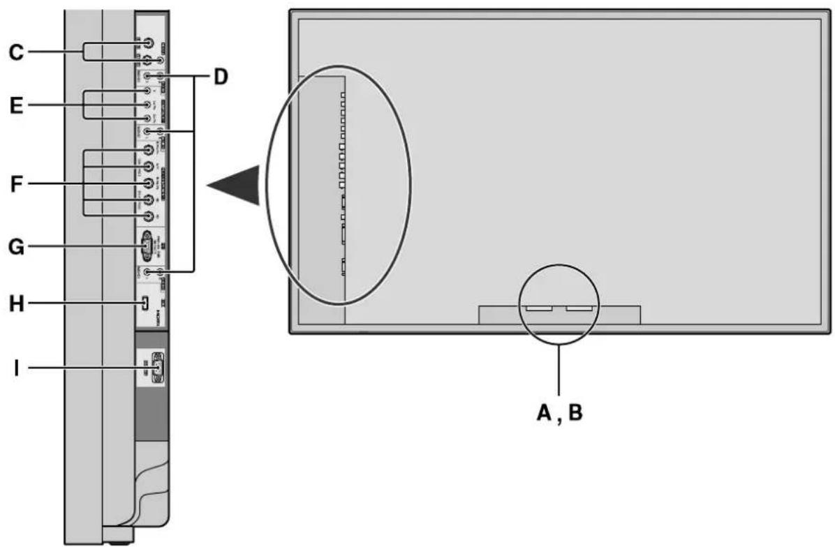
A AC IN
Connect the included power cord here.
BEXT SPEAKER L and R
Connect speakers here. Maintain the correct polarity.
Connect the (positive) speaker wire to the XT
SPEAKER terminal and the (negative) speaker wire to the EXT SPEAKER terminal on both LEFT and RIGHT channels.
Please refer to your speaker's owner's manual.
CVIDEO1, 2, 3 (BNC, RCA, S-Video)
Connect VCR's, DVD's or Video Cameras, etc. here.
D AUDIO1, AUDIO2, AUDIO3
These are audio input terminals.
The input is selectable. Set which video image to allot them from the SOUND menu screen.
E COMPONENT 1
Connect DVD's, High Definition or Laser Discs, etc. here.
F PC2/COMPONENT2
PC2: You can connect an analog RGB
signal and the synchronization signal.
COMPONENT2: You can connect DVDs, High
Definition sources, Laser Discs, etc. here.
This input can be set for use with an RGB or component source (see page 19).

HIGH-DEFINITION MULTIMEDIA INTERFAGE
G PC1 (D-Sub)
Connect an analog RGB signal from a computer, etc. here.
H HDMI
Connect a digital signal from a source with a HDMI output.
See page 30 for the details of Supported Signals.
RS-232C
Never connect any component to this connector without first consulting your Pioneer installation technician.
This connector is used for plasma display setup adjustments.
Information
- For Y/CB/Cr, connect to the COMPONENT1 or PC2/COMPONENT2 terminals.
- For SCART, this unit provides three ways to connect:
SCART1: Connect R/G/B and composite sync. to the PC2/COMPONENT2 terminals. (R, G, B and HD connector)
SCART2: Connect R/G/B to the COMPONENT2 terminals and composite sync. to the VIDEO1 terminal.
SCART3: Connect R/G/B and composite sync. to the PC1 terminal.
Remote Control
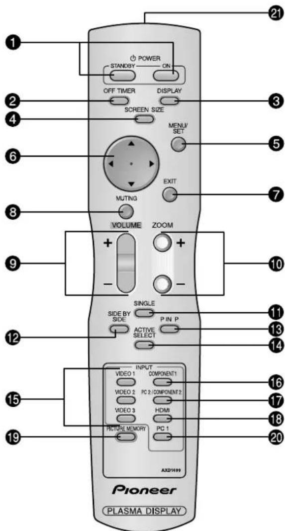
1 POWER ON/STANDBY
Switches the power on/standby.
(This does not operate when STANDBY/ON indicator of the main unit is off.)
OFF TIMER
Activates the off timer for the unit.
3 DISPLAY
Displays the source settings on the screen.
4 SCREEN SIZE
Automatically detects the signal and sets the aspect ratio.
SCREEN SIZE button is not active for all signals.
5 MENU/SET
Press this button to access the OSD controls.
Press this button during the display of the main menu to go to the sub menu.
6 CURSOR ( / / /)
Use these buttons to select items or settings and to adjust settings or switch the display patterns.
7 EXIT
Press this button to exit the OSD controls in the main menu. Press this button during the display of the sub menu to return to the previous menu.
MUTING
Mutes the sound.
9 VOLUME (+ / - )
Adjusts the sound volume.
10 ZOOM (+ / -)
Enlarges or reduces the image.
1 SINGLE
Cancels the split screen mode.
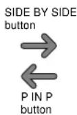
SIDE BY SIDE
Press this button to show a couple of pictures in the side-by-side mode.
PINP
Press this button to show a couple of pictures in the picture-in-picture mode.
14 ACTIVE SELECT
Press this button to make the desired picture activate during split screen mode.
When the PICTURE FREEZE function is operating, this button can be used to display still images on the subscreen.
VIDEO1,2,3
Press these buttons to select the input directly.
These inputs can also be selected using the INPUT/ EXIT button on the monitor.
16 COMPONENT1
Press this button to select the input directly.
This input can also be selected using the INPUT/EXIT button on the monitor.
PC2/COMPONENT2
Press this button to select the input directly.
This input can also be selected using the INPUT/EXIT button on the monitor.
16 HDMI
Press this button to select the input directly.
This input can also be selected using the INPUT/EXIT button on the monitor.
See page 30 for the details of Supported Signals.
19 PICTURE MEMORY
Switches sequentially between picture memory settings 1 to 6.
PC1
Press this button to select the input directly.
This input can also be selected using the INPUT/EXIT button on the monitor.
Remote control signal transmitter
Transmits the remote control signals.
POWER
To turn the unit ON and OFF:
- Plug the power cord into an active AC power outlet.
- Press the Power button (on the unit).
The monitor's STANDBY/ON indicator turns red and the standby mode is set.
- Press the POWER ON button (on the remote control) to turn on the unit.
The monitor's STANDBY/ON indicator will light up (green) when the unit is on. - Press the POWER STANDBY button (on the remote control) or the Power button (on the unit) to turn off the unit.
The monitor's STANDBY/ON indicator turns red and the standby mode is set (only when turning off the unit with the remote control).
VOLUME
To adjust the sound volume:
- Press and hold the VOLUME button (on the remote control or the unit) to increase to the desired level.
- Press and hold the VOLUME button (on the remote control or the unit) to decrease to the desired level.
MUTING
To mute the sound:
Press the MUTING button on the remote control to mute the sound press again to restore.
DISPLAY
To check the settings:
- The screen changes each time the DISPLAY button is pressed.
- If the button is not pressed for approximately three seconds, the menu turns off.
DIGITAL ZOOM
Digital zoom specifies the picture position and enlarges the picture.
- (Be sure ZOOM NAV is off)
Press the ZOOM (+ or -) button to display magnifying glass. ( )
To change the size of the picture:
Press the ZOOM+ button and enlarge the picture.
A press of the ZOOM- button will reduce the picture and return it to its original size.
To change the picture position:
Select the position with the buttons.
- Press the EXIT button to delete the pointer.
OFF TIMER
To set the off timer:
The off timer can be set to turn the power off after 30, 60, 90 or 120 minutes.
- Press the OFF TIMER button to start the timer at 30 minutes.
- Press the OFF TIMER button to the desired time.
- The timer starts when the menu turns off.
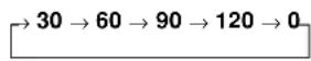
OFFTIMER 30
the off timer:
- Press the OFF TIMER button twice in a row.
- The off timer is canceled.

Note:
After the power is turned off with the off timer ... A slight current is still supplied to the monitor. When you are leaving the room or do not plan to use the system for a long period of time, turn off the power of the monitor.
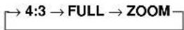
SCREEN SIZE Operation (manual)
With this function, you can select one of six screen sizes.
When viewing videos or digital video discs
-
Press the SCREEN SIZE button on the remote control.
-
Within 3 seconds ...
Press the SCREEN SIZE button again.
The screen size switches as follows:
4:3→FULL→WIDE→ZOOM→2.35:1→14:9
When a 720P or 1080I signal is input:
FULL 2.35:1
When displaying enhanced split screen:
4:3 FULL
The screen size is fixed to FULL when 720P or 1080I is input.
4:3 size screen

The normal size screen is displayed.
- The picture has the same size as video pictures with a 4:3 aspect ratio.
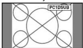
FULL size screen
The image is expanded in the horizontal direction.
- Images compressed in the horizontal direction ("squeezed images") are expanded in the horizontal direction and displayed on the entire screen with correct linearity. (Normal images are expanded in the horizontal direction.)
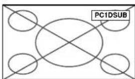
WIDE size screen
The picture is expanded in the horizontal and vertical directions at different ratios.
- Use this for watching normal video programs (4:3) with a wide screen.
ZOOM size screen

The picture is expanded in the horizontal and vertical direction, maintaining the original proportions.
- Use this for theater size (wide) movies, etc.
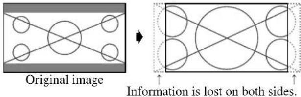
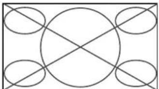
2.35:1 size screen
The squeezed film image is expanded to fulfill the entire screen at a ratio of 2.35:1. Black bands do not appear at the top and bottom but information is lost on the left and right margins.
-
This feature is available when the input signal is video, component (480I, 480P, 576I, 576P, 720P, 1080I) or RGB (525P or 625P signal from a scan converter) or HDMI (480I, 480P, 720P, 1080I, 576P).
-
If black bands appear on the top and bottom in the full size screen, select the 2.35:1 size screen to avoid phosphor burn-in.
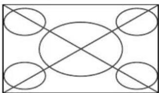
14:9 size screen

The image is displayed at a 14:9 aspect ratio.
- This feature is available when the input signal is video, component (480I, 480P, 576I, 576P) or RGB (525P or 625P signal from a scan converter) or HDMI (480I, 480P, 576P).
Note:
Do not allow the displayed in 4:3 mode for an extended period. This can cause a phosphor burn-in.
SCREEN SIZE Operation with Computer Signals
Switch to the wide screen mode to expand the 4:3 image to fill the entire screen.
-
Press the SCREEN SIZE button on the remote control.
-
Within 3 seconds ...
Press the SCREEN SIZE button again.
The screen size switches as follows:
When displaying enhanced split screen:
4:3 FULL
4:3 size screen (4:3 or SXGA 5:4)

The picture has the same size as the normal computer image.
FULL size screen
The image is expanded in the horizontal direction.
ZOOM size screen

When wide signals are input.
FULL size screen

Information
Supported resolution
See page 27 for details on the display output of the various VESA signal standards supported by the monitor.
"D BY D", a way of displaying pixels in a one-to-one correspondence with input signals, can be switched only when a 1280 dot x 768 line signal is input.
When 852 (848) dot × 480 line wide VGA* signals with a vertical frequency of 60~Hz and horizontal frequency of 31.7 (31.0) kHz are input
Select an appropriate setting for RGB SELECT mode referring to the "Table of Signals Supported" on page 27.
- "VGA", "SVGA" and "SXGA" are registered trademarks of IBM, Inc. of the United States.
Note:
Do not allow the displayed in 4:3 mode for an extended period. This can cause a phosphor burn-in.
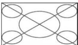
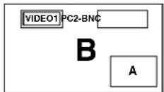
Showing a couple of pictures on the screen at the same time
- A PC-input picture may not be displayed in these modes, depending on the input signal specifications.
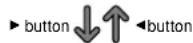
- Press the button to select a screen mode from among single mode, side-by-side, and picture-in-picture.
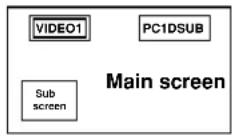
Note:
Picture A and B on the above screen are not always of the same height.
Information
Split screen operations may not function depending on the combination of input signals. In the table below, "O" means Yes, "×" means No.
- Split screen operations may not function depending on the type of the PC signals.
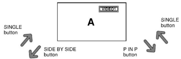
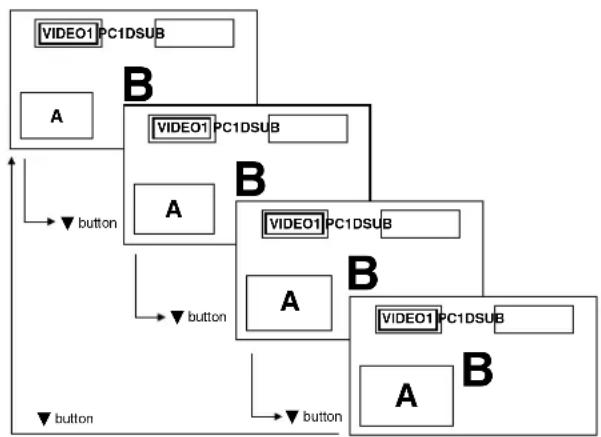
Operations in the Side-by-side mode
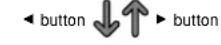
To change the picture size, press the cursor or button.
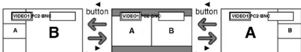
Button Side-by-Side2-R Side-by-Side1 Side-by-Side2-L
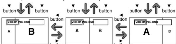
Side-by-Side4-R Side-by-Side3 Side-by-Side4-L
To swap the picture on the right and the left, press the cursor button.
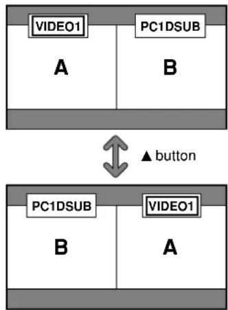
To make the desired picture active, press the ACTIVE SELECT button.
Operations in the Picture-in-picture mode
To move the position of the sub screen, press the cursor or button.
Top Left

button
Top Right
Bottom Left
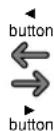
Bottom Right
To change the size of the sub screen, press the button.
To make the desired picture active, press the ACTIVE SELECT button.
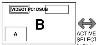
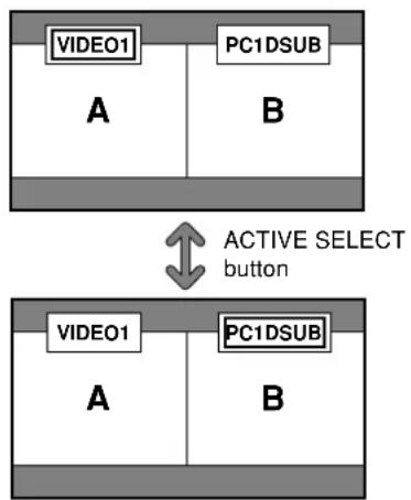
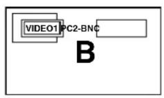
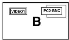
Selecting the input signals to be displayed
- Press the ACTIVE SELECT button to make the desired picture active.
- Press the PC1,VIDEO1,2,3,COMPONENT1,PC2/ COMPONENT2 or HDMI button to change the selection of the input signal.
The INPUT/EXIT button on the monitor can also be used to change the selection.
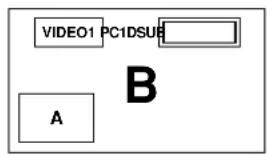
Zooming up pictures
- Press the ACTIVE SELECT button to make the desired picture active.
- Use the ZOOM (+ or -) button to enlage the picture. For details, see "DIGITAL ZOOM" on page 7.
Adjusting the OSD controls
- Press the ACTIVE SELECT button to make the desired picture active.
- Press the MENU/SET button to display the MAIN MENU.
- Adjust the setting to your preference. For details, see "OSD (On Screen Display) Controls" on page 12.
Note:
During enhanced split screen, some functions of OSD controls are not available.
Menu Operations
The following describes how to use the menus and the selected items.
- Press the MENU/SET button on the remote control to display the MAIN MENU.
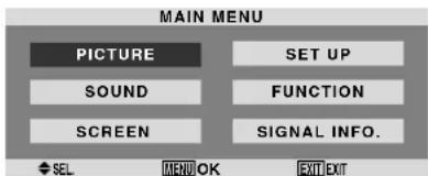
- Press the cursor buttons on the remote control to highlight the menu you wish to enter.
- Press the MENU/SET button on the remote control to select a sub menu or item.
- Adjust the level or change the setting of the selected item by using the cursor buttons on the remote control.
- The adjustments or the settings that are stored in memory. The change is stored until you change it again.
- Repeat steps 2-5 to adjust an additional item, or press the EXIT button on the remote control to return to the main menu.
- When adjusting using the bar at the bottom of the screen, press the or button within 5 seconds. If not, the current setting is set and the previous screen appears.
Note: The main menu disappears by pressing the EXIT button.
Setting the language for the menus
The menu display can be set to one of seven languages.
Example: Setting the menu display to "DEUTSCH"
On "LANGUAGE" of "SET UP" menu, select "DEUTSCH".
Information
■ Language settings
ENGLISH English ITALIANO Italian
DEUTSCH....German SVENSKA ....Swedish
FRANCAIS .... French PYCKM.Russian
ESPANOL ....... Spanish
Menu Tree
:Shaded areas indicate the default value. - +: Press the or button to adjust.
| Main menu Sub menu Sub menu 2 Sub menu 3 RESET | REFERENCE | ||||
| PICTURE PICTURE MEMORY OFF/MEMORY1-6 YES 15 | |||||
| CONTRAST | ←→+ 0←52→72 | YES 15 | |||
| BRIGHTNESS | ←→+ 0←32→64 | YES 15 | |||
| SHARPNESS | ←→+ 0←16→32 | YES 15 | |||
| COLOR | ←→+ 0←32→64 | YES 15 | |||
| TINT | R←→G 0←32→64 | YES 15 | |||
| DNR OFF/LOW/MID/HIGH | YES 15 | ||||
| COLOR TEMP. | LOW/MIDDLE LOW/MIDDLE/HIGH | YES 16 | |||
| WHITE BALANCE | R.HIGH | ←→+ 0←40→70 | YES 16 | ||
| G.HIGH | ←→+ 0←40→70 | YES 16 | |||
| B.HIGH | ←→+ 0←40→70 | YES 16 | |||
| R.LOW | ←→+ 0←40→70 | YES 16 | |||
| G.LOW | ←→+ 0←40→70 | YES 16 | |||
| B.LOW | ←→+ 0←40→70 | YES 16 | |||
| RESET | OFF←→ON | YES 16 | |||
| GAMMA | 2.1←-2.2←-2.3→2.4 | YES 16 | |||
| LOW TONE | AUTO←→1←...→3 | YES 16 | |||
| SET UP LEVEL | 0←→3.75←→7.5 | YES 17 | |||
| COLOR MGT | RED | Y←→M 0←32→64 | YES 17 | ||
| GREEN | C←→Y 0←32→64 | YES 17 | |||
| BLUE | M←→C 0←32→64 | YES 17 | |||
| YELLOW | G←→R 0←32→64 | YES 17 | |||
| MAGENTA | R←→B 0←32→64 | YES 17 | |||
| CYAN | B←→G 0←32→64 | YES 17 | |||
| RESET | OFF←→ON | YES 17 | |||
| PURECINEMA | ON←→OFF | YES 17 | |||
| AV SELECTION | DEFAULT/MOVIE1/MOVIE2/STANDARD/DYNAMIC | YES 17 | |||
| Main menu Sub menu Sub menu 2 Sub menu 3 RESET | REFERENCE | ||||
| SOUND | BASS | ←→+ 0←13→26 | YES 18 | ||
| TREBLE | ←→+ 0←13→26 | YES 18 | |||
| BALANCE | L←→R -22←0→22 | YES 18 | |||
| AUDIO INPUT1 | VIDEO 1-3 / COMPNT 1-2 / PC1DSUB / PC2-BNC | YES 18 | |||
| AUDIO INPUT2 | VIDEO 1-3 / COMPNT 1-2 / PC1DSUB / PC2-BNC | YES 18 | |||
| AUDIO INPUT3 | VIDEO 1-3 / COMPNT 1-2 / PC1DSUB / PC2-BNC | YES 18 | |||
| HDMI INPUT | ON←→OFF | YES 18 | |||
| Main menu Sub menu Sub menu 2 Sub menu 3 RESET | REFERENCE | ||||
| SCREEN SCREEN SIZE ZOOM/4:3/FULL/WIDE/14:9/2.35:1 NO NO | |||||
| V POSITION | ←→+ -64←0→64 | YES 18 | |||
| H POSITION | ←→+ -128←0→127 | YES 18 | |||
| V.SIZE | ←→+ 0←→64 | YES 18 | |||
| H.SIZE | ←→+ 0←→64 | YES 18 | |||
| AUTO PICTURE | ON←→OFF*2 | NO 18 | |||
| PHASE*1 | ←→+ *2 0←→64 | YES 18 | |||
| CLOCK*1 | ←→+ *2 0←→64→128 | YES 18 | |||
| Main menu Sub menu Sub menu 2 Sub menu 3 RESET | REFERENCE | ||||
| SET UP | LANGUAGE | ENGLISH/DEUTSCH/FRANÇAIS/ESPÁNOL/ITALIANO/SVENSKA/PYÇCKNI | NO 12 | ||
| BNC INPUT | RGB←→COMPONENT←→SCART1←→SCART2 | YES 19 | |||
| D-SUB INPUT | RGB←→SCART3 | YES 19 | |||
| HD SELECT | 1080I/1035I/540P | NO 19 | |||
| RGB SELECT AUTO/STILL/MOTION/WIDE1/WIDE2/WIDE3/WIDE4/DTV YES 19 | |||||
| HDMI SET UP | COLOR1←→COLOR2 | NO 20 | |||
| COLOR SYSTEM | AUTO/PAL/PAL-M/PAL-N/PAL 60/SECAM/4.43 NTSC/3.58NTSC | NO 20 | |||
| BACK GROUND | BLACK/GRAY | YES 20 | |||
| SIDE MASK | 0←→3←→15 | YES 21 | |||
| S1/S2 | AUTO←→OFF | YES 21 | |||
| DISPLAY OSD | ON←→OFF | YES 21 | |||
| OSD ADJUST | TOP LEFT←→TOP CENTER←→TOP RIGHT←→BTM LEFT←→BTM CENTER←→BTM RIGHT | YES 21 | |||
| ALL RESET | ON←→OFF | — 21 | |||
| FUNCTION POWER MGT. ON←→OFF YES 22 | |||||
| INPUT SKIP ON←→OFF YES 22 | |||||
| SUB. P DETECT AUTO←→OFF YES 22 | |||||
| ZOOM NAV | OFF←→S BY S←→BTM LFT←→BTM RGT←→TOP RGT←→TOP LFT | YES | 23 | ||
| PICTURE FREEZE | OFF←→S BY S1←→S BY S2←→BTM LEFT←→BTM RIGHT←→TOP RIGHT←→TOP LEFT | YES | 23 | ||
| LONG LIFE | MANUAL/AUTO | YES 23 | |||
| ABL | 100/75/50/25 | YES 24 | |||
| ORBITER | OFF/AUTO1/AUTO2 | YES 24 | |||
| INVERSE/WHITE | OFF/INVERSE/WHITE | YES 24 | |||
| SCREEN WIPER | ON/OFF | YES 24 | |||
| SOFT FOCUS | OFF/LEVEL1-4 | YES 24 | |||
| OSD ORBITER | ON/OFF | YES 25 | |||
| OSD CONTRAST | LOW/NORMAL | YES 25 | |||
| Main menu Sub menu Sub menu 2 Sub menu 3 RESET | REFERENCE | ||||
| SIGNAL INFO. | — | 25 | |||
1 Only when AUTO PICTURE is OFF.
2 PC only
Information
Restoring the factory default settings
Select "ALL RESET" under the SET UP menu. Note that this also restores other settings to the factory defaults.
Picture Settings Menu
Storing picture settings
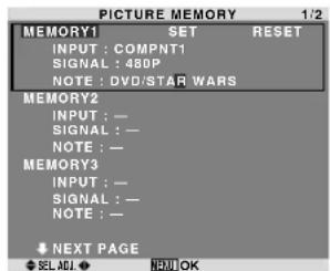
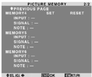
This function allows you to store in memory the current input signal and PICTURE menu settings and to recall these settings when necessary.
There are six picture memories, and notes of up to 15 characters can be added to each.
Example: Storing picture settings at MEMORY1
On "PICTURE MEMORY" of "PICTURE" menu, select "MEMORY1", then press the MENU/SET button.
The "PICTURE MEMORY" screen appears.
Information
PICTURE MEMORY Settings
OFF: Picture memory not used.
MEMORY1 to 6: Picture memory with the specified number used. Maximum memories are 6, not depending on inputs.
Setting the memory
- Use the and button to select the desired memory place, MEMORY1 to MEMORY6.
- Use the and buttons to select "SET", then press the MENU/SET button.
- If necessary, input a note.
Resetting the memory
Use the and button to select the desired memory place, MEMORY1 to MEMORY6, then use the and
- buttons to select "RESET", and finally press the MENU/SET button.
The memory is cleared, and "—" is displayed in the "INPUT", "SIGNAL" and "NOTE" columns.
Inputting notes
- Use the and buttons to select "NOTE", then press the MENU/SET button.
- Input the note.
Use the and button to select the character.
Use the and buttons to move the cursor.
Use the EXIT button to delete the character at the cursor position.
- When you have finished inputting the note, press the MENU/SET button.
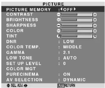
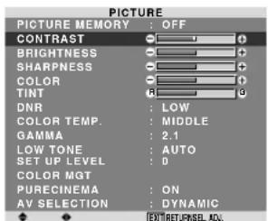
Adjusting the picture
The contrast, brightness, sharpness, color and tint can be adjusted as desired.
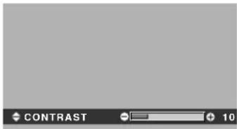
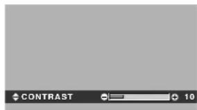
Example: Adjusting the contrast
On "CONTRAST" of "PICTURE" menu, adjust the contrast.
Note: If "CAN NOT ADJUST" appears ...
When trying to enter the PICTURE submenu, make sure AV SELECTION is not set to DEFAULT.
Information
Picture adjustment screen
CONTRAST: Changes the picture's white level.
BRIGHTNESS: Changes the picture's black level.
SHARPNESS: Changes the picture's sharpness.
Adjusts picture detail ofVIDEO display.
COLOR: Changes the color density.
TINT: Changes the picture's tint. Adjust for natural colored skin, background, etc.
Adjusting the computer image
Only the contrast and brightness can be adjusted when a computer signal is connected.
Restoring the factory default settings
Select "DEFAULT" under the "AV SELECTION" settings.
Reducing noise in the picture
Use these settings if the picture has noise due to poor reception or when playing video tapes on which the picture quality is poor.
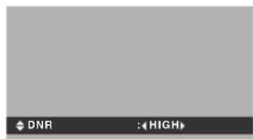
Example: Setting "HIGH"
On "DNR" of "PICTURE" menu, select "HIGH".
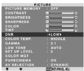
Information
DNR
- “DNR” stands for Digital Noise Reduction.
- This function reduces noise in the picture.
Types of noise reduction
There are three types of noise reduction. Each has a different level of noise reduction.
The effect increases stronger in the order of LOW, MID and HIGH.
OFF: Turns the noise reduction function off.
Setting the color temperature
Use this procedure to set color tone produced by the plasma display.
Example: Setting "HIGH"
On "COLOR TEMP" of "PICTURE" menu, select "HIGH".
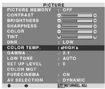
Information
Setting the color temperature
LOW: Redder
MIDDLE LOW: Slightly red
MIDDLE: Standard (slightly bluer)
HIGH:Bluer
Adjusting the color to the desired level
Use this procedure to adjust the white balance for each color temperature to achieve the desired color quality.
Example: Adjusting the "R.HIGH" of "HIGH" color temperature
On "COLOR TEMP" of "PICTURE" menu, select "HIGH", then press the MENU/SET button.
The "WHITE BALANCE" screen appears.
On "R.HIGH", adjust the white balance.
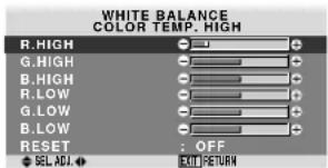

Information
Adjusting the white balance
R/G/B HIGH: White balance adjustment for white level
R/G/B LOW: White balance adjustment for black level
RESET: Resets settings to the factory default values.
Use and buttons to select "ON", then press the MENU/SET button.
Restoring the factory default settings
Select "RESET" under the WHITE BALANCE menu.
Changing the Gamma Curve
This feature adjusts the brightness of the midtone areas while keeping shadows and highlights unchanged.
Example: Setting "2.3"
On "GAMMA" of "PICTURE" menu, select 2.3
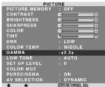
Information
■ GAMMA settings
The picture becomes darker as the number increases (in the sequence of 2.1, 2.2, 2.3, 2.4).
- These values are approximate.
Making the Low Tone adjustments
This feature allows more detailed tone to be reproduced especially in the dark area.
Example: Setting "2"
On "LOW TONE" of "PICTURE" menu, select "2".
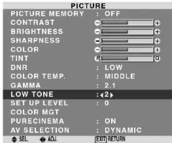
Information
LOW TONE settings
AUTO: Will automatically appraise the picture and make adjustments.
1: Will apply the dither method suitable for still pictures.
2: Will apply the dither method suitable for motion pictures.
3: Will apply the error diffusion method.
Adjusting the pedestal level (black level)
This feature adjusts the video black level in a video image.
Example: Setting "3.75"
On "SET UP LEVEL" of "PICTURE" menu, select "3.75".
| PICTURE | |
| PICTURE MEMORY : OFF | |
| CONTRAST | |
| BRIGHTNESS | |
| SHARPNESS | |
| COLOR | |
| TINT | |
| DNR | LOW |
| COLOR TEMP. | MIDDLE |
| GAMMA | 2.1 |
| LOW TONE | AUTO |
| SET UP LEVEL | 3.75 |
| COLOR MGT | |
| PURECINEMA | ON |
| AV SELECTION | DYNAMIC |
| EXIT RETURNSEL ADJ. | |
Information
SET UP LEVEL settings
0: Normal status
3.75: 3.75% lower than normal
7.5: 7.5% lower than normal
Adjusting the colors
Use this procedure to adjust hue and color density for red, green, blue, yellow, magenta and cyan.
You can accentuate the green color of trees, the blue of the sky, etc.
Example: Adjusting the color management for blue
On "PICTURE" menu, select "COLOR MGT", then press the MENU/SET button.
The "COLOR MGT" screen appears.
On "BLUE" of "COLOR MGT", adjust the color management.
| COLOR MGT | |
| RED | Y |
| GREEN | C |
| BLUE | M |
| YELLOW | G |
| MAGENTA | R |
| CYAN | B |
| RESET | OFF |
| SEL ADJ. | RETURN |
Information
COLOR MGT settings
RED: Makes red's adjustment
GREEN: Makes green's adjustment
BLUE: Makes blue's adjustment
YELLOW: Makes yellow's adjustment
MAGENTA: Makes magenta's adjustment
CYAN: Makes cyan's adjustment
RESET: Resets settings to the factory default value.
Use and buttons to select "ON", then press the MENU/SET button.
Setting the picture to suit the movie
The film image is automatically discriminated and projected in an image mode suited to the picture.
[NTSC, PAL, PAL60, 480I (60Hz), 525I (60Hz), 576I (50Hz), 625I (50Hz), 1035I (60Hz), 1080I (60Hz) only]
Example: Setting the "PURECINEMA" to "OFF"
On "PURECINEMA" of "PICTURE" menu, select "OFF".
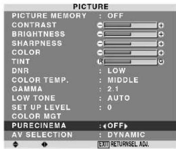
Information
PURECINEMA
ON: Automatic discrimination of the image and projection in PURECINEMA.
OFF: PURECINEMA does not function.
Setting the picture modes according to the brightness of the room
There are four picture modes that can be used effectively according to the environment in which you are viewing the display.
Example: Setting the "MOVIE1" mode
On "AV SELECTION" of "PICTURE" menu, select "MOVIE1".
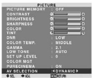

Information
Types of AV SELECTION
MOVIE1, 2: Set this mode when watching video in a dark room.
This mode provides darker, finer pictures, like the screen in movie theaters.
For a darker image, select MOVIE2.
STANDARD: Set this mode when watching video in a bright room.
This mode provides pictures with distinct differences between light and dark sections.
DYNAMIC: This mode provides brighter pictures than STANDARD.
DEFAULT: Use this to reset the picture to the factory default settings.
STANDARD is the default setting when PC signal is input.
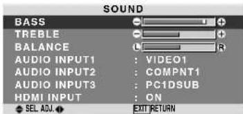
SOUND Settings Menu
Adjusting the treble, bass and left/right balance and audio input select
The treble, bass and left/right balance can be adjusted to suit your tastes.
Example: Adjusting the bass
On "BASS" of "SOUND" menu, adjust the bass.
Note: If "CAN NOT ADJUST" appears...
Set "AUDIO INPUT" on the SOUND menu correctly.
Information
■ SOUND settings menu
BASS: Controls the level of low frequency sound.
TREBLE: Controls the level of high frequency sound.
BALANCE: Controls the balance of the left and right channels.
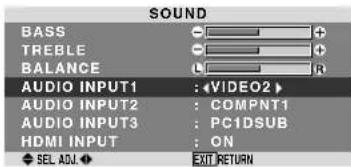
Setting the allocation of the audio connectors
Setting the AUDIO 1, 2, and 3 connectors to the desired input.
Example: Setting "AUDIO INPUT1" to "VIDEO 2"
On "AUDIO INPUT1" of "SOUND" menu, select "VIDEO2".
The available sources depend on the settings of input.
Information
AUDIO INPUT
A single audio input cannot be selected as the audio channel for more than one input terminal.
HDMI INPUT
ON: Enables the digital audio input signal transmitted via the HDMI terminal.
OFF: Disables the digital audio input signal.
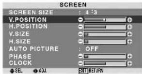
SCREEN Settings Menu
Adjusting the Position, Size, PHASE, CLOCK
The position of the image can be adjusted and flickering of the image can be corrected.
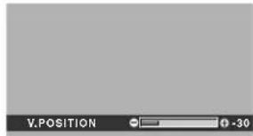
Example: Adjusting the vertical position in the normal mode
On "V POSITION" of "SCREEN" menu, adjust the position. The mode switches as follows each time the or button is pressed:
4:3 FULL
- The mode can also be switched by pressing the SCREEN SIZE button on the remote control.
- The settings on the SCREEN menu are not preset at the factory.
Information
When "AUTO PICTURE" is "OFF
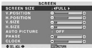
When Auto Picture is off, the PHASE and the CLOCK items are displayed so that you can adjust them.
Adjusting the Auto Picture
ON: The CLOCK, PHASE and Position adjustments are made automatically.
Not available for digital ZOOM.
OFF: The CLOCK, PHASE and Position adjustments are made manually.
- If PHASE can't be adjusted, set Auto Picture to OFF and adjust manually.
Adjusting the position of the image
V. POSITION: Adjusts the vertical position of the image.
H.POsiTION: Adjusts the horizontal position of the image.
V.SIZE: Adjusts the vertical size of the image. (Except for WIDE mode)
H.SIZE: Adjusts the horizontal size of the image. (Except for WIDE mode)
PHASE*: Adjusts for flickering.
CLOCK*: Adjusts for striped patterns on the image.
- The CLOCK and PHASE features are available only when the "Auto Picture" is off.
- The AUTO PICTURE, PHASE and CLOCK are available only for RGB signals.
But, these features are not available for moving pictures on RGB, VIDEO or COMPONENT.
SET UP Settings Menu
Setting the PC2/COMPONENT2 connectors
Select whether to set the PC2/COMPONENT2 input to RGB and component or SCART1,2.
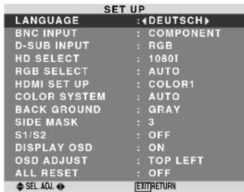
Example: Set the BNC INPUT mode to "RGB"
On "BNC INPUT" of "SET UP" menu, select "RGB".
| SET UP | |
| LANGUAGE | : ENGLISH |
| BNC INPUT | : RGB |
| D-SUB INPUT | : RGB |
| HD SELECT | : 1080I |
| RGB SELECT | : AUTO |
| HDMI SET UP | : COLOR1 |
| COLOR SYSTEM | : AUTO |
| BACK GROUND | : GRAY |
| SIDE MASK | : 3 |
| S1/S2 | : OFF |
| DISPLAY OSD | : ON |
| OSD ADJUST | : TOP LEFT |
| ALL RESET | : OFF |
| SEL ADJ. | EXIT RETURN |
Information
BNC INPUT Settings
RGB: Use the 5BNC terminals for HD, VD and RGB signals.
COMPONENT: Use the 3BNC terminals for component signals.
SCART1: Use the 4BNC terminals for RGB with composite sync. See page 5.
SCART2: Use the 3BNC terminals for RGB and the VIDEO1 terminal for composite sync. See page 5.
Setting the PC1 connector
Select one of the signals being transmitted to the PC1 terminal.
Example: Set the D-SUB INPUT mode to "SCART3"
On "D-SUB INPUT" of "SET UP" menu, select "SCART3".
| SET UP | |
| LANGUAGE | : ENGLISH |
| BNC INPUT | : COMPONENT |
| D-SUB INPUT | : «SCART3» |
| HD SELECT | : 1080I |
| RGB SELECT | : AUTO |
| HDMI SET UP | : COLOR1 |
| COLOR SYSTEM | : AUTO |
| BACK GROUND | : GRAY |
| SIDE MASK | : 3 |
| S1/S2 | : OFF |
| DISPLAY OSD | : ON |
| OSD ADJUST | : TOP LEFT |
| ALL RESET | : OFF |
| SEL ADJ. | EXIT RETURN |
Information
D-SUB INPUT Settings
RGB: Use the D-SUB terminal for RGB signals.
SCART3: Use the D-SUB terminal for RGB signal fed from SCART. See page 5.
Setting high definition images to the suitable screen size
Use this procedure to set whether the number of vertical lines of the input high definition image is 1080I or 1035I or 540P.
Example: Setting the "HD SELECT" mode to "1035I"
On "HD SELECT" of "SET UP" menu, select "1035I".
| SET UP | |
| LANGUAGE | : ENGLISH |
| BNC INPUT | : COMPONENT |
| D-SUB INPUT | : RGB |
| HD SELECT | :1035I |
| RGB SELECT | : AUTO |
| HDMI SET UP | : COLOR1 |
| COLOR SYSTEM | : AUTO |
| BACK GROUND | : GRAY |
| SIDE MASK | : 3 |
| S1/S2 | : OFF |
| DISPLAY OSD | : ON |
| OSD ADJUST | : TOP LEFT |
| ALL RESET | : OFF |
| SEL_ADJ. | EXJOYRETURN |
Information
HD SELECT modes
These 3 modes are not displayed in correct image automatically.
1080I: Standard digital broadcasts
1035l: Japanese "High Vision" signal format
540P: Special Digital broadcasts (for example : DTC100)
Setting a computer image to the correct RGB select screen
With the computer image, select the RGB Select mode for a moving image such as (video) mode, wide mode or digital broadcast.
Example: Setting the "RGB SELECT" mode to "MOTION"
On“RGB SELECT"of“SETUP”menu,select“MOTION”.
| SET UP | |
| LANGUAGE | : ENGLISH |
| BNC INPUT | : COMPONENT |
| D-SUB INPUT | : RGB |
| HD SELECT | : 10801 |
| RGB SELECT | : Motion |
| HDMI SET UP | 1024×768 |
| COLOR SYSTEM | : AUTO |
| BACK GROUND | : GRAY |
| SIDE MASK | : 3 |
| S1/S2 | : OFF |
| DISPLAY OSD | : ON |
| OSD ADJUST | : TOP LEFT |
| ALL RESET | : OFF |
| SEL_ADJ. | EXJOYRETURN |
Information
RGB SELECT modes
One of these 8 modes must be selected in order to display the following signals correctly.
AUTO: Select the suitable mode for the specifications of input signals as listed in the table "Computer input signals supported by this system" on page 27.
STILL: To display VESA standard signals. (Use this mode for a still image from a computer.)
MOTION: The video signal (from a scan converter) will be converted to RGB signals to make the picture more easily viewable. (Use this mode for a motion image from a computer.)
WIDE1: When an 852 dot × 480 line signal with a horizontal frequency of 31.7kHz is input, the image may be compressed horizontally. To prevent this, set RGB SELECT to WIDE1.
WIDE2: When an 848 dot × 480 line signal with a horizontal frequency of 31.0kHz is input, the image may be compressed horizontally. To prevent this, set RGB SELECT to WIDE2.
WIDE3: When an 1920 dot × 1200 line signal with a horizontal frequency of 74.0kHz is input, the image may be compressed horizontally. To prevent this, set RGB SELECT to WIDE3.
WIDE4: When an 1280dot× 768 line signal with a horizontal frequency of 59.8kHz or an 1680dot× 1050 line signal with a horizontal frequency of 60kHz is input, the image may be compressed horizontally. To prevent this, set RGB SELECT to WIDE4.
DTV: Set this mode when watching digital broadcasting (480P).
See page 27 for the details of the above settings.
Setting the black level for HDMI signal
Set the black level for the signal transmitted via the HDMI terminal.
Example: Setting "COLOR2"
On "HDMI SET UP" of "SET UP" menu, select "COLOR2".
| SET UP | |
| LANGUAGE | : ENGLISH |
| BNC INPUT | : COMPONENT |
| D-SUB INPUT | : RGB |
| HD SELECT | : 1080I |
| RGB SELECT | : AUTO |
| HDMI SET UP | : COLOR2 |
| COLOR SYSTEM | : AUTO |
| BACK GROUND | : GRAY |
| SIDE MASK | : 3 |
| S1/S2 | : OFF |
| DISPLAY OSD | : ON |
| OSD ADJUST | : TOP LEFT |
| ALL RESET | : OFF |
| SEL ADJ. | EXIT RETURN |
Information
HDMI SET UP settings
COLOR1: When connected to the SET TOP BOX, DVD etc. Change "COLOR1" into "COLOR2" if the black level appears gray.
COLOR2: Darker black level (real black).
Setting the video signal format
Use these operations to set the color systems of composite video signals or Y/C input signals.
Example: Setting the color system to "3.58 NTSC"
On "COLOR SYSTEM" of "SET UP" menu, select "3.58NTSC".
| SET UP | |
| LANGUAGE | : ENGLISH |
| BNC INPUT | : COMPONENT |
| D-SUB INPUT | : RGB |
| HD SELECT | : 1080I |
| RGB SELECT | : AUTO |
| HDMI SET UP | : COLOR1 |
| COLOR SYSTEM | : (3.58NTSC) |
| BACK GROUND | : GRAY |
| SIDE MASK | : 3 |
| S1/S2 | : OFF |
| DISPLAY OSD | : ON |
| OSD ADJUST | : TOP LEFT |
| ALL RESET | : OFF |
| SEL ADJ. | OUT/RETURN |
Information
Video signal formats
Different countries use different formats for video signals. Set to the color system used in your current country.
AUTO: The color systems are automatically identified and the format is set accordingly.
PAL: This is the standard format used mainly in the United Kingdom and Germany.
SECAM: This is the standard format used mainly in France and Russia.
4.43 NTSC, PAL60: This format is used for videos in countries using PAL and SECAM video signals.
3.58 NTSC: This is the standard format used mainly in the United States and Japan.
PAL-M: This is the standard format used mainly in Brazil.
PAL-N: This is the standard format used mainly in Argentina.
Setting the background color when no signal is being input
The color displayed on the background when there is no signal can be set to gray.
Example: Setting "BACK GROUND" to "BLACK"
On "BACK GROUND" of "SET UP" menu, select "BLACK".
| SET UP | |
| LANGUAGE | : ENGLISH |
| BNC INPUT | : COMPONENT |
| D-SUB INPUT | : RGB |
| HD SELECT | : 1080I |
| RGB SELECT | : AUTO |
| HDMI SET UP | : COLOR1 |
| COLOR SYSTEM | : AUTO |
| BACK GROUND | : BLACK |
| SIDE MASK | : 3 |
| S1/S2 | : OFF |
| DISPLAY OSD | : ON |
| OSD ADJUST | : TOP LEFT |
| ALL RESET | : OFF |
| SEL_ADJ. | EXIT |
Information
BACK GROUND Settings
BLACK: Sets the background color to black.
GRAY: Sets the background color to gray.
Setting this makes it easier to see that there is no signal.
Setting the gray level for the SIDE MASK
Use this procedure to set the gray level for the parts on the screen on which nothing is displayed when the screen is set to the 4:3 size and D BY D size.
Example: Setting "SIDE MASK" to "5"
On "SIDE MASK" of "SET UP" menu, select "5".
| SET UP | |
| LANGUAGE | : ENGLISH |
| BNC INPUT | : COMPONENT |
| D-SUB INPUT | : RGB |
| HD SELECT | : 1080I |
| RGB SELECT | : AUTO |
| HDMI SET UP | : COLOR1 |
| COLOR SYSTEM | : AUTO |
| BACK GROUND | : GRAY |
| SIDE MASK | : 45 |
| S1/S2 | : OFF |
| DISPLAY OSD | : ON |
| OSD ADJUST | : TOP LEFT |
| ALL RESET | : OFF |
| SEL ADJ. | EXIT RETURN |
Information
SIDE MASK settings
This adjusts the brightness of the black (the gray level) for the sides of the screen.
The standard is 0 (black). The level can be adjusted from 0 to 15. The factory setting is 3 (dark gray).
Setting the screen size for S1/S2 video input
If the S-video signal contains screen size information, the image will be automatically adjusted to fit the screen when this S1/S2 is set to AUTO.
This feature is available only when an S-video signal is input via theVIDEO3 terminal.
Example: Setting "S1/S2" to "AUTO"
On "S1/S2" of "SET UP" menu, select "AUTO".
| SET UP | |
| LANGUAGE | : ENGLISH |
| BNC INPUT | : COMPONENT |
| D-SUB INPUT | : RGB |
| HD SELECT | : 1080I |
| RGB SELECT | : AUTO |
| HDMI SET UP | : COLOR1 |
| COLOR SYSTEM | : AUTO |
| BACK GROUND | : GRAY |
| SIDE MASK | : 3 |
| S1/S2 | : AUTO |
| DISPLAY OSD | : ON |
| OSD ADJUST | : TOP LEFT |
| ALL RESET | : OFF |
| SEL ADJ. | EXIT RETURN |
Information
S1/S2 settings
AUTO: Adjusts the screen size automatically according to the S1/S2 video signal.
OFF: Turns the S1/S2 function off.
Turning on/off the information display
When this is set to OFF, the information will not be displayed even if you press the DISPLAY button.
Example: Turning the DISPLAY OSD off
On "DISPLAY OSD" of "SET UP" menu, select "OFF".
| SET UP | |
| LANGUAGE | : ENGLISH |
| BNC INPUT | : COMPONENT |
| D-SUB INPUT | : RGB |
| HD SELECT | : 1080I |
| RGB SELECT | : AUTO |
| HDMI SET UP | : COLOR1 |
| COLOR SYSTEM | : AUTO |
| BACK GROUND | : GRAY |
| SIDE MASK | : 3 |
| S1/S2 | : OFF |
| DISPLAY OSD | :OFF |
| OSD ADJUST | : TOP LEFT |
| ALL RESET | : OFF |
| SEL ADJ. | EXIT RETURN |
Information
DISPLAY OSD settings
ON: The informations on screen size, volume control, etc. will be shown.
OFF: The informations on screen size, volume control, etc. will not be shown.
Setting the position of the menu
Adjusts the position of the menu when it appears on the screen.
Example: Set the position to "TOP CENTER"
On "OSD ADJ." of "SET UP" menu, select "TOP CENTER".
| SET UP | |
| LANGUAGE | : ENGLISH |
| BNC INPUT | : COMPONENT |
| D-SUB INPUT | : RGB |
| HD SELECT | : 1080I |
| RGB SELECT | : AUTO |
| HDMI SET UP | : COLOR1 |
| COLOR SYSTEM | : AUTO |
| BACK GROUND | : GRAY |
| SIDE MASK | : 3 |
| S1/S2 | : OFF |
| DISPLAY OSD | : ON |
| OSD ADJUST | : (TOP CENTER) |
| ALL RESET | : OFF |
| SEL. ADJ. | OUTRETN |
Information
OSD ADJUST settings
| TOP LEFT | TOP CENTER | TOP RIGHT |
| BTM LEFT | BTM CENTER | BTM RIGHT |
Resetting to the default values
Use these operations to restore all the settings (PICTURE, SOUND, SCREEN, SET UP, etc) to the factory default values.
Refer to page 13 for items to be reset.
On "ALL RESET" of "SET UP" menu, select "ON", then press the MENU/SET button.
| SET UP | |
| LANGUAGE | : ENGLISH |
| BNC INPUT | : COMPONENT |
| D-SUB INPUT | : RGB |
| HD SELECT | : 10801 |
| RGB SELECT | : AUTO |
| HDMI SET UP | : COLOR1 |
| COLOR SYSTEM | : AUTO |
| BACK GROUND | : GRAY |
| SIDE MASK | : 3 |
| S1/S2 | : OFF |
| DISPLAY OSD | : ON |
| OSD ADJUST | : TOP LEFT |
| ALL RESET | : ON |
| ALL RESET |
| SETTING NOW |
When the "SETTING NOW" screen disappears, then all the settings are restored to the default values.
Function Settings Menu
Setting the power management for computer images
This energy-saving (power management) function automatically reduces the monitor's power consumption if no operation is performed for a certain amount of time.
Example: Turning the power management function on
On "POWER MGT:" of "FUNCTION" menu, select "ON".
| FUNCTION | |
| POWER MGT. | :ON |
| INPUT SKIP | : OFF |
| SUB. P DETECT | : AUTO |
| ZOOM NAV | : BTM LEFT |
| PICTURE FREEZE | : S BY S1 |
| LONG LIFE | : MANUAL |
| SEL. ADJ. | :EXTRETURN |
Information
Power management function
- The power management function automatically reduces the monitor's power consumption if the computer's keyboard or mouse is not operated for a certain amount of time. This function can be used when using the monitor with a computer.
- If the computer's power is not turned on or if the computer and selector tuner are not properly connected, the system is set to the off state.
- For instructions on using the computer's power management function, refer to the computer's operating instructions.
Power management settings
ON: In this mode the power management function is turned on.
OFF: In this mode the power management function is turned off.
Power management function and STANDBY/ON indicator
The STANDBY/ON indicator indicates the status of the power management function. See below for indicator status and description.
STANDBY/ON indicator
| Power management mode | STANDBY/ON Indicator | Power management operating status | Description | Turning the picture back on |
| On | Green | Not activated. | Horizontal and vertical synchronizing signals are present from the computer. | Picture already on. |
| Off | Red | Activated. | Horizontal and/or vertical synchronizing signals are not sent from the computer. | Operate the keyboard or mouse. The picture reappears. |
Setting the Input Skip
When this is ON, signals which are not present will be skipped over and only pictures whose signals are being transmitted will be displayed.
This setting is valid only for the INPUT/EXIT button on the unit.
Example: Set to "ON"
On "INPUT SKIP" of "FUNCTION" menu, select "ON".
| FUNCTION | |
| POWER MGT. | OFF |
| INPUT SKIP | ON |
| SUB. P DETECT | AUTO |
| ZOOM NAV | BTM LEFT |
| PICTURE FREEZE | S BY S1 |
| LONG LIFE | MANUAL |
| SEL_ADJ. | E001)RETURN |
Information
INPUT SKIP settings
OFF: Regardless of the presence of the signal, scan and display all signals.
ON: If no input signal is present, skip that signal.
- “SETTING NOW” will appear during the input search.
Erasing the sub screen image when there is no input signal
This function automatically erases the black frame of the sub screen when there is no sub screen input signal.
This feature is available only when the picuture-in-picuture mode is selected.
Example: Set to "OFF"
On "SUB. P DETECT" of "FUNCTION" menu, select "OFF".
| FUNCTION | |
| POWER MGT. | : OFF |
| INPUT SKIP | : OFF |
| SUB. P DETECT | :OFF |
| ZOOM NAV | : BTM LEFT |
| PICTURE FREEZE | : S BY S1 |
| LONG LIFE | : MANUAL |
| SEL. ADJ. | [EOU] RETURN |
Information
SUB.P DETECT Function
- The sub screen disappears when the input signal is lost.
- Loss of the input signal means a condition in which the video signal and the sync signal are not present.
- Under conditions in which the sub screen has disappeared, the ZOOM NAV and PICTURE FREEZE functions will not work. The SCREEN SIZE button will not function either.
SUB.P DETECT settings
AUTO: The black frame disappears 3 seconds after the input signal is lost.
OFF: Turns off the SUB. P DETECT function.
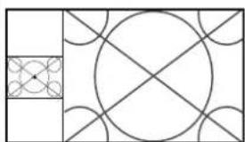
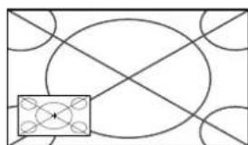
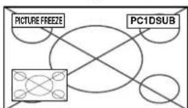
Displaying the entire image during DIGITAL ZOOM operations
Use this function to display the entire image within the sub screen together with an enlarged image on the main screen.
Example: Setting "ZOOM NAV" to "S BY S"
On “ZOOM NAV” of “FUNCTION” menu, select “S BY S”.
| FUNCTION | |
| POWER MGT. | OFF |
| INPUT SKIP | OFF |
| SUB. P DETECT | AUTO |
| ZOOM NAV | S BY S |
| PICTURE FREEZE | S BY S1 |
| LONG LIFE | MANUAL |
| SEL ADV. | EXTRUCTION |
Information
ZOOM NAV Function
- This feature is available only for PC1 or PC2 input signals.
- This feature does not function during multi screen mode.
- This feature does not function while PICTURE FREEZE is operating.
- Providing a 2-screen display will cancel this function.
ZOOM NAV settings
OFF: Will not show the entire image on the sub screen.
S BY S: Will show the entire image on the sub screen of side-by-side mode.
BTM LFT\~TOP LFT: Will show the entire image on the sub screen of picture-in-picture mode.
Side-by-Side Picture-in-Picture
Zoom+/- button

SINGLE button


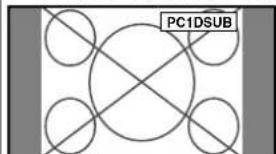
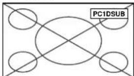
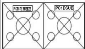
Displaying still images in the sub screen
This feature enables display in the sub screen of still images captured by pressing the ACTIVE SELECT button.
Example: Setting "PICTURE FREEZE" to "BTM LEFT"
On "PICTURE FREEZE" of FUNCTION" menu, select BTM LEFT".
| FUNCTION | |
| POWER MGT. | OFF |
| INPUT SKIP | OFF |
| SUB, P DETECT | AUTO |
| ZOOM NAV | BTM LEFT |
| PICTURE FREEZE | (BTM LEFT) |
| LONG LIFE | MANUAL |
| SEL. ADJ. | EXO1) RETURN |
Information
PICTURE FREEZE Function
- This feature is available only for PC1 or PC2 input signals.
- This feature does not function during multi screen mode.
- Digital zoom is not available while this function is operating.
- A further press of the ACTIVE SELECT button while this function is operating will cancel this function.
- Providing a 2-screen display will cancel this function.
PICTURE FREEZE settings
OFF: Will not show the still image.
S BY S1, 2: The still images captured by pressing the ACTIVE SELECT button will be shown on the sub screen of side-by-side mode.
BTM LEFT~TOP LEFT: The still images captured by pressing the ACTIVE SELECT button will be shown on the sub screen of picture-in-picture mode.
Side-by-Side Picture-in-Picture
ACTIVE SELECT button
ACTIVE SELECT button
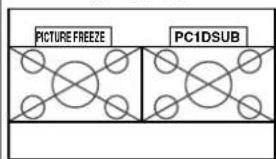
S BY S1
or S BY S2
Reducing burn-in of the screen
The brightness of the screen, the position of the picture, positive/negative mode and screen wiper are adjusted to reduce burn-in of the screen.
On "LONG LIFE" of "FUNCTION" menu, select "MANUAL", then press the MENU/SET button.
The "LONG LIFE" screen appears.
| LONG LIFE | |
| ABL:100 | |
| ORBITER:OFF | |
| INVERSE/WHITE:OFF | |
| SCREEN WIPER:OFF | |
| SOFT FOCUS:OFF | |
| OSD ORBITER:ON | |
| OSD CONTRAST:LOW | |
| SEL. ADJ:EXTENT RETURN |
Information
When set to AUTO
Set automatically, as described below.
ABL: 100
ORBITER: AUTO1
INVERSE/WHITE: OFF
SCREEN WIPER: OFF
SOFT FOCUS: OFF
OSD ORBITER: ON
OSD CONTRAST: LOW
ABL (Auto Brightness Limiter)
Use this to activate the brightness limiter.
Example: Setting "ABL" to "75"
On "ABL" of "LONG LIFE" menu, select "75".
| LONG LIFE | |
| ABL: | :75 |
| ORBITER: | OFF |
| INVERSE/WHITE: | OFF |
| SCREEN WIPER: | OFF |
| SOFT FOCUS: | OFF |
| OSD ORBITER: | ON |
| OSD CONTRAST: | LOW |
| SEL ADJ: | EXITRETURN |
Information
ABL settings
100: The brightness of the screen is adjusted automatically to suit the picture quality.
75, 50, 25: Sets maximum brightness.
The brightness level decreases in the order of 75, 50,
-
25 provides minimum brightness.
-
These values are approximate.
ORBITER
Use this to set the picture shift.
Example: Setting "ORBITER" to "AUTO1"
On "ORBITER" of "LONG LIFE" menu, select "AUTO1".
| LONG LIFE | |
| ABL:100 | |
| ORBITER:4AUTO1 | |
| INVERSE/WHITE:OFF | |
| SCREEN WIPER:OFF | |
| SOFT FOCUS:OFF | |
| OSD ORBITER:ON | |
| OSD CONTRAST:LOW | |
| SEL ADJ:EXTRETURN |
Information
ORBITER settings
OFF: Orbiter mode does not function.
This is the default setting when PC signal is input.
AUTO1: The picture moves around the screen intermittently, making the picture smaller. This is the default setting when a Video, a COMPONENT or an HDMI signal is input. Set to "OFF" when these signals are not used.
AUTO2: The picture moves around the screen intermittently, making the picture bigger.
- When a Video, a COMPONENT or an HDMI signal is input, the AUTO1 and 2 functions will affect only the moving picture and will not make the screen smaller or bigger.
INVERSE/WHITE
Use this to set the inverse mode or to display a white screen.
Example: Setting "INVERSE/WHITE" to "WHITE"
On "INVERSE/WHITE" of "LONG LIFE" menu, select "WHITE".
| LONG LIFE | |
| ABL:100 | |
| ORBITER:OFF | |
| INVERSE/WHITE:《WHITE》 | |
| SCREEN WIPER:OFF | |
| SOFT FOCUS:OFF | |
| OSD ORBITER:ON | |
| OSD CONTRAST:LOW | |
| SEL ADJ:RETURN |
Information
INVERSE/WHITE Settings
OFF: Inverse/white mode does not function.
INVERSE: The picture is displayed alternately between positive image and negative image.
WHITE: The entire screen turns white.
SCREEN WIPER
When this is set to ON, a white vertical bar moves repeatedly from the left and of the screen to the right end at a constant speed.
Example: Setting "SCREEN WIPER" to "ON"
On "SCREEN WIPER" of "LONG LIFE" menu, select "ON".
| LONG LIFE | |
| ABL:100 | |
| ORBITER:OFF | |
| INVERSE/WHITE:OFF | |
| SCREEN WIPER:ON | |
| SOFT FOCUS:OFF | |
| OSD ORBITER:ON | |
| OSD CONTRAST:LOW | |
| SEL. ADJ:EXT RETURN |
Information
SCREEN WIPER
ON: The white vertical bar appears.
OFF: Screen wiper mode does not function.
SOFT FOCUS
Reduces edges and softens the image.
Example: Setting "SOFT FOCUS" to "LEVEL2"
On "SOFT FOCUS" of "LONG LIFE" menu, select "LEVEL2".
| LONG LIFE | |
| ABL:100 | |
| ORBITER:OFF | |
| INVERSE/WHITE:OFF | |
| SCREEN WIPER:OFF | |
| SOFT FOCUS:LEVEL2 | |
| OSD ORBITER:ON | |
| OSD CONTRAST:LOW | |
| SEL ADJ:RETURN |
Information
SOFT FOCUS settings
OFF: Turns the SOFT FOCUS function off.
LEVEL1, 2, 3, 4: Activates the SOFT FOCUS setting.
The higher numbers create a softer image.
"SHARPNESS" can not be adjusted on the "PICTURE" menu.
OSD ORBITER
Use this to set OSD menu shift.
Example: Setting "OSD ORBITER" to "OFF"
On "OSD ORBITER" of "LONG LIFE" menu, select "OFF".
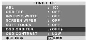
Information
OSD ORBITER settings
ON: The position of the menu will be shifted by eight dots each time OSD is displayed.
OFF: OSD will be displayed at the same position.
OSD CONTRAST
Use this to reduce the brightness of OSD menu.
Example: Setting "OSD CONTRAST" to "NORMAL"
On "OSD CONTRAST" of "LONG LIFE" menu, select "NORMAL".
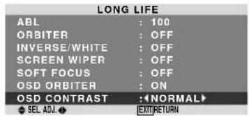
Information
OSD CONTRAST settings
NORMAL: OSD brightness is set to normal.
LOW: OSD brightness is set to lower.
Signal Information Menu
Checking the frequencies, polarities of input signals, and resolution
Use this function to check the frequencies and polarities of the signals currently being input from a computer, etc. On "MAIN MENU", select "SIGNAL INFO", then press the MENU/SET button.
The "SIGNAL INFORMATION" is displayed.
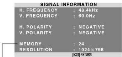
PC: MEMORY will be displayed.
Others: MODE will be displayed.
| Pin No. | Signal (Analog) |
| 1 | Red |
| 2 | Green or sync-on-green |
| 3 | Blue |
| 4 | No connection |
| 5 | Ground |
| 6 | Red ground |
| 7 | Green ground |
| 8 | Blue ground |
| 9 | No connection |
| 10 | Sync signal ground |
| 11 | No connection |
| 12 | Bi-directional DATA (SDA) |
| 13 | Horizontal sync or Composite sync |
| 14 | Vertical sync |
| 15 | Data clock |
Table of Signals Supported
Supported resolution
-
When the screen size is 4:3, each signal is converted to a 1024 dots × 768 lines signal. (Except for ^*2,3,4 )
-
When the screen size is D BY D, the picture is displayed in the original resolution.
-
When the screen size is FULL, each signal is converted to a 1365 dots × 768 lines signal. (Except for ^*3 )
Computer input signals supported by this system
| Model | Dots × lines | Vertical frequency (Hz) | Horizontal frequency (kHz) | Sync Polarity | Presence | Screen Size | RGB select*5 | Memory | ||||
| Horizontal | Vertical | Horizontal | Vertical | 4:3 | D BY D | FULL (16:9) | ||||||
| 640 × 400 | 70.1 | 31.5 | NEG | NEG | YES | YES | YES*2 | -- | YES | -- | 4 | |
| IBM PC/AT* compatible computers | 640 × 480 | 59.9 | 31.5 | NEG | NEG | YES | YES | YES | -- | YES | STILL | 5 |
| 72.8 | 37.9 | NEG | NEG | YES | YES | YES | -- | YES | STILL | 7 | ||
| 75.0 | 37.5 | NEG | NEG | YES | YES | YES | -- | YES | STILL | 8 | ||
| 85.0 | 43.3 | NEG | NEG | YES | YES | YES | -- | YES | -- | 9 | ||
| 100.4 | 51.1 | NEG | NEG | YES | YES | YES | -- | YES | -- | 41 | ||
| 120.4 | 61.3 | NEG | NEG | YES | YES | YES | -- | YES | -- | 42 | ||
| 848 × 480 | 60.0 | 31.0 | POS | POS | YES | YES | -- | -- | YES | WIDE2 | 19 | |
| 852 × 480*1 | 60.0 | 31.7 | NEG | NEG | YES | YES | -- | -- | YES | WIDE1 | 17 | |
| 800 × 600 | 56.3 | 35.2 | POS | POS | YES | YES | YES | -- | YES | STILL | 11 | |
| 60.3 | 37.9 | POS | POS | YES | YES | YES | -- | YES | STILL | 12 | ||
| 72.2 | 48.1 | POS | POS | YES | YES | YES | -- | YES | -- | 13 | ||
| 75.0 | 46.9 | POS | POS | YES | YES | YES | -- | YES | -- | 14 | ||
| 85.1 | 53.7 | POS | POS | YES | YES | YES | -- | YES | -- | 15 | ||
| 99.8 | 63.0 | POS | POS | YES | YES | YES | -- | YES | -- | 43 | ||
| 120.0 | 75.7 | POS | POS | YES | YES | YES | -- | YES | -- | 44 | ||
| 1024 × 768 | 60.0 | 48.4 | NEG | NEG | YES | YES | YES*3 | -- | YES | STILL | 24 | |
| 70.1 | 56.5 | NEG | NEG | YES | YES | YES*3 | -- | YES | -- | 25 | ||
| 75.0 | 60.0 | POS | POS | YES | YES | YES*3 | -- | YES | STILL | 26 | ||
| 85.0 | 68.7 | POS | POS | YES | YES | YES*3 | -- | YES | -- | 27 | ||
| 100.6 | 80.5 | NEG | NEG | YES | YES | YES*3 | -- | YES | -- | 45 | ||
| 1152 × 864 | 75.0 | 67.5 | POS | POS | YES | YES | YES | -- | YES | STILL | 51 | |
| 1280 × 768 | 56.2 | 45.1 | NEG | NEG | YES | YES | -- | YES | YES | WIDE1 | 52 | |
| 59.8*9 | 48.0*9 | NEG | POS | YES | YES | -- | YES | YES | WIDE4 | 23 | ||
| 69.8*9 | 56.0*9 | NEG | POS | YES | YES | -- | YES | YES | WIDE1 | 66 | ||
| 1280 × 800*9 | 60.0 | 49.7 | NEG | NEG | YES | YES | -- | -- | YES | WIDE1 | 21 | |
| 1280 × 854*9 | 60.0 | 53.1 | NEG | NEG | YES | YES | -- | -- | YES | WIDE2 | 37 | |
| 1360 × 765 | 60.0 | 47.7 | POS | POS | YES | YES | -- | -- | YES*3 | WIDE1 | 22 | |
| 1360 × 768 | 60.0 | 47.7 | POS | POS | YES | YES | -- | -- | YES*3 | WIDE1 | 22 | |
| 1376 × 768 | 59.9 | 48.3 | NEG | POS | YES | YES | -- | -- | YES | WIDE2 | 53 | |
| 1280 × 1024 | 60.0 | 64.0 | POS | POS | YES | YES | YES*4 | -- | YES | STILL | 29 | |
| 75.0 | 80.0 | POS | POS | YES | YES | YES*4 | -- | YES | -- | 30 | ||
| 85.0 | 91.1 | POS | POS | YES | YES | YES*4 | -- | YES | -- | 40 | ||
| 100.1 | 108.5 | POS | POS | YES | YES | YES*4 | -- | YES | -- | 47 | ||
| 1680 × 1050*9 | 60.0 | 65.3 | NEG | NEG | YES | YES | -- | -- | YES | WIDE4 | 38 | |
| 1600 × 1200 | 60.0 | 75.0 | POS | POS | YES | YES | YES | -- | YES | -- | 54 | |
| 65.0 | 81.3 | POS | POS | YES | YES | YES | -- | YES | -- | 55 | ||
| 70.0 | 87.5 | POS | POS | YES | YES | YES | -- | YES | -- | 56 | ||
| 75.0 | 93.8 | POS | POS | YES | YES | YES | -- | YES | -- | 57 | ||
| 85.0 | 106.3 | POS | POS | YES | YES | YES | -- | YES | -- | 58 | ||
| 1920 × 1200*9 | 60.0 | 74.6 | NEG | NEG | YES | YES | -- | -- | YES | WIDE2 | 81 | |
| 1920 × 1200RB*9 | 60.0 | 74.0 | NEG | NEG | YES | YES | -- | -- | YES | WIDE3 | 88 | |
| Apple Macintosh*6 *8 | 640 × 480 | 66.7 | 35.0 | Sync on G | Sync on G | -- | -- | YES | -- | YES | -- | 6 |
| 832 × 624 | 74.6 | 49.7 | Sync on G | Sync on G | -- | -- | YES | -- | YES | -- | 16 | |
| 1024 × 768 | 74.9 | 60.2 | Sync on G | Sync on G | -- | -- | YES*3 | -- | YES | WIDE1 | 28 | |
| 1152 × 870 | 75.1 | 68.7 | Sync on G | Sync on G | -- | -- | YES | -- | YES | WIDE1 | 39 | |
| 1440 × 900*9 | 60.0 | 56.0 | NEG | NEG | YES | YES | -- | -- | YES | -- | 89 | |
| Work Station (EWS4800)*8 | 1280 × 1024 | 60.0 | 64.6 | NEG | NEG | YES | YES | YES*4 | -- | YES | -- | 29 |
| 71.2 | 75.1 | NEG | NEG | YES | YES | YES*4 | -- | YES | -- | 48 | ||
| Work Station(HP)*8 | 1280 × 1024 | 72.0 | 78.1 | -- | -- | -- | -- | YES*4 | -- | YES | -- | 59 |
| Work Station (SUN)*8 | 1152 × 900 | 66.0 | 61.8 | C Sync | C Sync | -- | -- | YES | -- | YES | -- | 60 |
| 76.0 | 71.7 | C Sync | C Sync | -- | -- | YES | -- | YES | -- | 61 | ||
| 1280 × 1024 | 76.1 | 81.1 | C Sync | C Sync | -- | -- | YES*4 | -- | YES | -- | 30 | |
| Work Station (SGI) | 1024 × 768 | 60.0 | 49.7 | -- | -- | -- | -- | YES*3 | -- | YES | -- | 62 |
| 1280 × 1024 | 60.0 | 63.9 | -- | -- | -- | -- | YES*4 | -- | YES | -- | 29 | |
| IDC-3000G | ||||||||||||
| NTSC525P | 640 × 480 | 59.9 | 31.5 | NEG | NEG | YES | YES | YES*7 | -- | YES*7 | MOTION | 32 |
1 Only when using a graphic accelerator board that is capable of displaying 852 × 480 .
2 This signal is converted to a 1024 dots × 640 lines signal.
3 The picture is displayed in the original resolution.
4 The aspect ratio is 5:4. This signal is converted to a 960 dots × 768 lines signal.
5 Normally the RGB select mode suite for the input signals is set automatically. If the picture is not displayed properly, set the RGB mode prepared for the input signals listed in the table above.
6 To connect the monitor to Macintosh computer, use the monitor adapter (D-Sub 15-pin) to your computer's video port.
7 Other screen modes (ZOOM and WIDE) are available as well.
8 When viewing a moving picture at a vertical frequency greater than 65Hz , the picture may sometimes be unstable (jumpy). If this occurs, please set the refresh rate of the external equipment to 60Hz .
To view 480I@60Hz (480 interlaced lines, 60Hz refresh rate) or 576I@50Hz (576 interlaced lines, 50Hz refresh rate) when sync polarity is "Sync on Green", set "RGB SELECT" to "MOTION".
*9 CVT standard compliant.
NOTE:
- While the input signals comply with the resolution listed in the table above, you may have to adjust the position and size of the picture or the fine picture because of errors in synchronization of your computer.
- When a 1280 dots × 1024 lines signal or 1600 dots × 1200 lines signal is input to the monitor, the picture will be compressed.
This monitor has a resolution of 1365 dots × 768 lines. It is recommended that the input signal should be XGA, wide XGA, or equivalent. - With digital input some signals are not accepted.
- The sync may be disturbed when a nonstandard signal other than the aforementioned is input.
-
If you are connecting a composite sync signal, use the HD terminal.
-
"IBM PC/AT" and "XGA" are registered trademarks of International Business Machines, Inc. of the United States.
- "Apple Macintosh" is a registered trademark of Apple Computer, Inc. of the United States.
If the picture quality is poor or there is some other problem, check the adjustments, operations, etc., before requesting service.
| Symptom | Checks | Remedy |
| Mechanical sound is heard. | ·May be the sound from the cooling fans used to prevent over heating. | |
| The unit emits a crackling sound. | ·Are the image and sound normal? | ·If there are no abnormalities in the image and sound, the noise is caused by the cabinet reacting to changes in temperature. This will not affect performance. |
| Picture is disturbed.Sound is noisy.Remote control operates erroneously. | ·Is a connected component set directly in front or at the side of the display? | ·Leave some space between the display and the connected components. |
| The remote control does not work. | ·Are the remote control's batteries worn out? | ·Replace both batteries with new ones. |
| Monitor's power does not turn on when the remote control's power button is pressed. | ·Is the monitor's power cord plugged into a power outlet? | ·Plug the monitor's power cord into a power outlet. |
| ·Are all the monitor's indicators off? | ·Press the power button on the monitor to turn on the power. | |
| ·Are the remote control's batteries worn out? | ·Replace both batteries with new ones. | |
| Monitor does not operate when the remote control's buttons are pressed. | ·Is the remote control pointed at the monitor, or is there an obstacle between the remote control and the monitor? | ·Point the remote control at the monitor's remote control sensor when pressing buttons, or remove the obstacle. |
| ·Is direct sunlight or strong artificial light shining on the monitor's remote control sensor? | ·Eliminate the light by closing curtains, pointing the light in a different direction, etc. | |
| ·Are the remote control's batteries worn out? | ·Replace both batteries with new ones. | |
| No sound or picture is produced. | ·Is the monitor's power cord plugged into a power outlet? | ·Plug the monitor's power cord into a power outlet. |
| Picture appears but no sound is produced. | ·Is the volume set at the minimum? | ·Increase the volume. |
| ·Is the muting mode set? | ·Press the remote control's MUTING button. | |
| ·Are the speakers properly connected? | ·Connect the speakers properly. | |
| ·Is AUDIO INPUT set correctly? | ·Set AUDIO INPUT on the SOUND menu correctly. | |
| Poor picture with VIDEO signal input. | ·Improper control setting.Local interference.Cable interconnections.Input impedance is not correct level. | ·Adjust picture control as needed.Try another location for the monitor.Be sure all connections are secure. |
| Poor picture with RGB signal input. | ·Improper control setting.Incorrect RGB connector pin connections. | ·Adjust picture controls as needed.Check pin assignments and connections. |
| Tint is poor or colors are weak. | ·Are the tint and colors properly adjusted? | ·Adjust the tint and color (under PICTURE). |
| Nothing appears on screen. | ·Is the computer's power turned on? | ·Turn on the computer's power. |
| ·Is a source connected? | ·Connect source to the monitor. | |
| ·Is the power management function in the standby or off mode? | ·Operate the computer (move the mouse, etc.). | |
| Part of picture is cut off or picture is not centered. | ·Is the position adjustment appropriate? | ·Adjust the SCREEN properly. |
| Image is too large or too small. | ·Is the screen size adjustment appropriate? | ·Press the SCREEN SIZE button on the remote control and adjust properly. |
| Picture is unstable. | ·Is the computer's resolution setting appropriate? | ·Set to the proper resolution. |
| STANDBY/ON indicator is lighted in red. | ·Horizontal and / or vertical sync signal is not present when the Intelligent Power Manager control is on. | ·Check the input signal. |
| STANDBY/ON indicator is blinking in red. | ·The temperature inside the main unit has become too high and has activated the protector. | ·Promptly switch off the power of the main unit and wait until the internal temperature drops. See*1. |
| STANDBY/ON indicator is blinking in green and red, or green. | —— | ·Promptly switch off the power of the main unit. See *2. |
1 Overheat protector
If the monitor becomes too hot, the overheat protector will be activated and the monitor will be turned off. If this happens, turn off the power to the monitor and unplug the power cord. If the room where the monitor is installed is particularly hot, move the monitor to a cooler location and wait for the monitor to cool for 60 minutes. If the problem persists, contact your dealer.
2 In the following case, power off the monitor immediately and contact your dealer or authorized Service Center.
The monitor turns off 5 seconds after powering on and then the STANDBY/ON indicator blinks. It indicates that the power supply circuit, plasma display panel, temperature sensor, or one or more fans have been damaged.
Specifications
Screen Size 1351(H)× 760(V) mm
53.2" (H) × 29.9'' (V) inches
diagonal 61"
Aspect Ratio 16:9
Resolution 1365(H) × 768(V) pixels
Signals
Synchronization Range Horizontal: 15.5 to 110kHz
(automatic:step scan)
Vertical: 50.0 to 120Hz
(automatic:step scan)
Input Signals RGB, NTSC (3.58/4.43), PAL (B,G,M,N)
PAL60.SECAM,HD*,DVD*,DTV*
Input Terminals
PC
Visual 2 (Analog) BNC (R, G, B, H/CS, V) × I*2
Video
Visual 1 BNC × 1
Visual 2 RCA-pin × 1
Visual 3 S-Video:DIN 4-pin × 1
COMPONENT
Visual 1 RCA-pin (Y, PB[CB], PR[CR]) × 1^*1
Visual 2 BNC (Y, PB[CB], PR[CR]) × 1^1, 2
HDMI HDMI connector*
Audio
Stereo RCA× 3 (Selectable)
Current Rating 3.7A (maximum)
Power Consumption 540W (typical) (standby 1.8W)
Dimensions 1502 (W) × 912 (H) × 126(D) mm
59.1 (W) × 35.9 (H) × 5.0 (D) inches
Weight
68.0kg / 149.9 lbs (without stand)
Environmental Considerations
Operating Temperature 0^ to 40^ / 32^ to 104^
| Other Features | Motion compensated 3D Scan Converter (NTSC, PAL, 480I, 576I, 525I, 625I, 1035I, 1080I), 2-3 pull down Converter (NTSC, 480I, 525I, 1035I, 1080I (60Hz)), 2-2 pull down Converter (PAL, 576I, 625I, NTSC, 480I, 525I), Digital Zoom Function (100-900% Selectable), Self Diagnosis, Image Burn reduction tools (ABL, INVERSE, WHITE, ORBITER, SCREEN WIPER), Color Temperature select (high/middle/middle low/low, user has 4 memories), Auto Picture, Input Skip, Color MGT, Low Tone (3 mode), Gamma Correction (4 mode), Plug and play (DDC1, DDC2b, HDMI:E-DDC), Split screen operations |
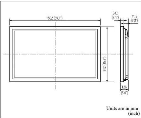
The features and specifications may be subject to change without notice.
*COMPONENT input signals supported on this system
480P(60Hz) 480I(60Hz) 525P(60Hz)
*The 5-BNC connectors are used as PC2 and COMPONENT2 input.
Select one of them under "BNC INPUT".
*3HDMI input signals supported on this system.
Supported Signals
- 640×480P @ 60Hz ·1920×1080I @ 50Hz
- 1280×720P @ 60Hz - 720×576P @ 50Hz
- 1920×1080I @ 60Hz - 1440 (720)×576P @ 50Hz
- 720×480P @ 60Hz - 1280×720P @ 50Hz
1440(720)×4801@60Hz
Note: In some cases a signal on the plasma monitor may not be displayed properly. The problem may be an inconsistency with standards from the source equipment (DVD, Set-top box, etc...). If you do experience such a problem please contact your dealer and also the manufacturer of the source equipment.
Mode d'emploi
A AC IN (ENTREE DU CORDON
D'ALIMENTATION ELECTRIQUE CA)
HDMI, the HDMI logo and High-Definition Multimedia Interface are trademarks or registered trademarks of HDMI Licensing LLC.
F PC2/COMPONENT2
INV./FD BLANC: ARRET
SCREEN WIPER: ARRET
SOFT FOCUS: ARRET
POSITION OSM: MARCHE
CONTRASTE OSM: BASSE
59.1 (L) × 35,9 (l) × 5,0 (P) pouces
Poids 68.0kg / 145.9 lbs (sans support)
ESPANOL ....... Spanish
Published by Pioneer Corporation. Copyright © 2004 Pioneer Corporation. All rights reserved.