
NPD 5500 - Browser AUDIOVOX - Free user manual and instructions
Find the device manual for free NPD 5500 AUDIOVOX in PDF.
| Product type | GPS navigator for vehicle |
| Brand | Audiovox |
| Model | NPD 5500 |
| Dimensions (approx.) | 1-DIN standard (178 x 50 x 160 mm) |
| Weight (approx.) | 1.5 kg |
| Power supply | 12 V DC (vehicle battery) |
| Power consumption | 10 A fuse recommended |
| Display | External monitor (4:3 or 16:9) |
| GPS antenna | Active, with cable and metal plate |
| Mapping | Map DVD/CD |
| Remote control | Infrared, with optional bracket |
| Main functions | GPS navigation, voice guidance, voice messages via speaker, map display, route calculation |
| Signal inputs | Speedometer signal (digital or analog), reverse signal, low beam |
| Audio outputs | 3.5 mm jack socket for external speaker or MA 1300 adapter |
| Multimedia options | Hands-free kit, Multimedia Center MC 5400 |
| Mounting angle | -10° to +30° (adjustable in the Diagnostic menu) |
| Mounting temperature | Minimum 60°F (15°C) for antenna and remote control adhesive |
| Maintenance and cleaning | Clean with a soft, dry cloth; avoid abrasive products |
| Safety | Do not mount in airbag deployment zone; respect field of view; disconnect battery before installation |
| Spare parts and repairability | GPS antenna, cables, remote control, monitor, mounting frame, brackets; repair by qualified personnel |
| General information | Manual of 22 pages (FR, EN, ES); subject to technical modifications |
| Vehicle compatibility | Vehicles with 12 V on-board voltage, negative ground |
| Commissioning | Initialization 2-10 minutes; calibration via 10 min road test |
Frequently Asked Questions - NPD 5500 AUDIOVOX
User questions about NPD 5500 AUDIOVOX
0 question about this device. Answer the ones you know or ask your own.
Ask a new question about this device
Download the instructions for your Browser in PDF format for free! Find your manual NPD 5500 - AUDIOVOX and take your electronic device back in hand. On this page are published all the documents necessary for the use of your device. NPD 5500 by AUDIOVOX.
USER MANUAL NPD 5500 AUDIOVOX
natural_image
Abstract geometric logo design with black angular shapes and a white central point (no text or symbols)AUDIOVOX®
NPD 5500
NPC 5400
Installation instructions Mode d'installation Instrucciones de montaje
natural_image
Diagram showing a hand holding a tool above a building interior, with an inset close-up of a person working on a chair (no text or symbols present)
natural_image
Illustration of a battery pack with arrows indicating direction, no text or symbols present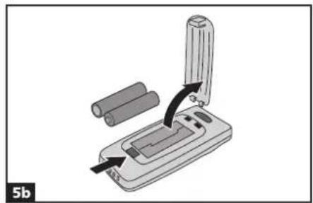
natural_image
Diagram of a handheld device with cylindrical components and an arrow indicating rotation or movement (no text or symbols)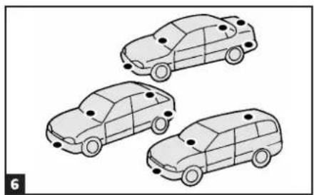
natural_image
Three line-drawn car illustrations in a row, no text or symbols present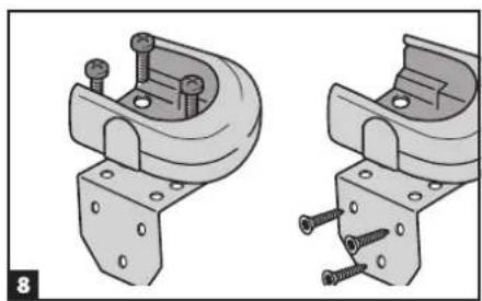
natural_image
Technical illustration of two mechanical clamp assemblies with screws and brackets (no text or symbols)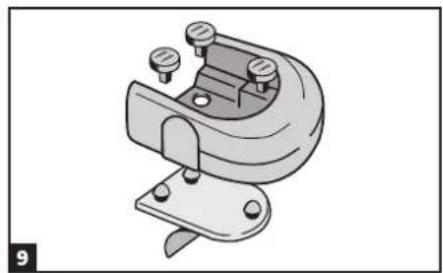
natural_image
Mechanical clamp or bracket component with mounting holes and a curved top (no text or symbols visible)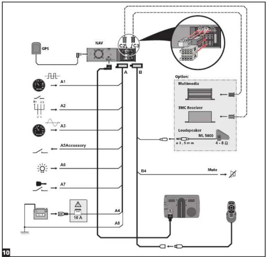
flowchart
graph TD
    GPS["GPS"] --> NAV["NAV"]
    NAV --> A["A"]
    NAV --> B["B"]
    NAV --> C2["C2 / C3"]
    NAV --> C3["C3 / C2"]
    NAV --> C4["C3 / C2"]
    NAV --> C5["C3 / C2"]
    NAV --> C6["C3 / C2"]
    NAV --> C7["C3 / C2"]
    NAV --> C8["C3 / C2"]
    NAV --> C9["C3 / C2"]
    NAV --> C10["C3 / C2"]
    NAV --> C11["C3 / C2"]
    NAV --> C12["C3 / C2"]
    NAV --> C13["C3 / C2"]
    NAV --> C14["C3 / C2"]
    NAV --> C15["C3 / C2"]
    NAV --> C16["C3 / C2"]
    NAV --> C17["C3 / C2"]
    NAV --> C18["C3 / C2"]
    NAV --> C19["C3 / C2"]
    NAV --> C20["C3 / C2"]
    NAV --> C21["C3 / C2"]
    NAV --> C22["C3 / C2"]
    NAV --> C23["C3 / C2"]
    NAV --> C24["C3 / C2"]
    NAV --> C25["C3 / C2"]
    NAV --> C26["C3 / C2"]
    NAV --> C27["C3 / C2"]
    NAV --> C28["C3 / C2"]
    NAV --> C29["C3 / C2"]
    NAV --> C30["C3 / C2"]
    NAV --> C31["C3 / C2"]
    NAV --> C32["C3 / C2"]
    NAV --> C33["C3 / C2"]
    NAV --> C34["C3 / C2"]
    NAV --> C35["C3 / C2"]
    NAV --> C36["C3 / C2"]
    NAV --> C37["C3 / C2"]
    NAV --> C38["C3 / C2"]
    NAV --> C39["C3 / C2"]
    NAV --> C40["C3 / C2"]
    NAV --> C41["C3 / C2"]
    NAV --> C42["C3 / C2"]
    NAV --> C43["C3 / C2"]
    NAV --> C44["C3 / C2"]
    NAV --> C45["C3 / C2"]
    NAV --> C46["C3 / C2"]
    NAV --> C47["C3 / C2"]
    NAV --> C48["C3 / C2"]
    NAV --> C49["C3 / C2"]
    NAV --> C50["C3 / C2"]
    NAV --> C51["C3 / C2"]
    NAV --> C52["C3 / C2"]
    NAV --> C53["C3 / C2"]
    NAV --> C54["C3 / C2"]
    NAV --> C55["C3 / C2"]
    NAV --> C56["C3 / C2"]
    NAV --> C57["C3 / C2"]
    NAV --> C58["C3 / C2"]
    NAV --> C59["C3 / C2"]
    NAV --> C60["C3 / C2"]
    NAV --> C61["C3 / C2"]
    NAV --> C62["C3 / C2"]
    NAV --> C63["C3 / C2"]
    NAV --> C64["C3 / C2"]
    NAV --> C65["C3 / C2"]
    NAV --> C66["C3 / C2"]
    NAV --> C67["C3 / C2"]
    NAV --> C68["C3 / C2"]
    NAV --> C69["C3 / C2"]
    NAV --> C70["C3 / C2"]
    NAV --> C71["C3 / C2"]
    NAV --> C72["C3 / C2"]
    NAV --> C73["C3 / C2"]
    NAV --> C74["C3 / C2"]
    NAV --> C75["C3 / C2"]
    NAV --> C76["C3 / C2"]
    NAV --> C77["C3 / C2"]
    NAV --> C78["C3 / C2"]
    NAV --> C79["C3 / C2"]
    NAV --> C80["C3 / C2"]
[Non-Text]
一
[Non-Text]
[Non-Text]
[Non-Text]
[Non-Text]
[Non-Text]
[Non-Text]
[Non-Text]
[Non-Text]
____
[Non-Text]
[Non-Text]
[Non-Text]
[Non-Text]
[Non-Text]
[Non-Text]
[Non-Text]
[Non-Text]
[Non-Text]
[Non-Text]
[Non-Text]
[Non-Text]
[Non-Text]
[Non-Text]
[Non-Text]
[Non-Text]
[Non-Text]
[Non-Text]
[Non-Text]
[Non-Text]
[Non-Text]
[Non-Text]
[Non-Text]
[Non-Text]
[Non-Text]
[Non-Text]
[Non-Text]
[Non-Text]
[Non-Text]
[Non-Text]
[Non-Text]
[Non-Text]
[Non-Text]
[Non-Text]
[Non-Text]
[Non-Text]
[Non-Text]
[Non-Text]
[Non-Text]
[Non-Text]
[Non-Text]
[Non-Text]
[Non-Text]
[Non-Text]
[Non-Text]
[Non-Text]
[Non-Text]
[Non-Text]
[Non-Text]
[Non-Text]
[Non-Text]
[Non-Text]
[Non-Text]
[Non-Text]
[Non-Text]
[Non-Text]
[Non-Text]
[Non-Text]
[Non-Text]
[Non-Text]
[Non-Text]
[Non-Text]
[Non-Text]
[Non-Text]
[Non-Text]
[Non-Text]
[Non-Text]
[Non-Text]
[Non-Text]
[Non-Text]
[Non-Text]
[Non-Text]
[Non-Text]
[Non-Text]
[Non-Text]
[Non-Text]
[Non-Text]
[Non-Text]
[Non-Text]
[Non-Text]
[Non-Text]
[Non-Text]
[Non-Text]
[Non-Text]
[Non-Text]
[Non-Text]
[Non-Text]
—
1
The Ground Truth image displays a single, solid horizontal line. According to Rule 2 (UNDERSCORE & LINE RULES), if the GT contains lines used for stylistic emphasis or as background (like ruled paper), the OCR result must ignore them. The line in the GT is clearly a stylistic or background line, not a placeholder for text. Therefore, the OCR should not have output any underscores. Outputting `____` constitutes an error under Rule 2, as it hallucinates placeholder symbols where none are semantically intended. Hence, the OCR result is inconsistent with the Ground Truth.
The Ground Truth image displays a single, solid horizontal line. According to Rule 2 (UNDERSCORE & LINE RULES), if the GT contains lines used for stylistic emphasis or as background (like ruled paper), the OCR result must ignore them. The line in the GT is clearly a stylistic or background line, not a placeholder for text. Therefore, the OCR should not have output any underscores. Outputting `____` constitutes an error under Rule 2, as it hallucinates placeholder symbols where none are semantically intended. Hence, the OCR result is inconsistent with the Ground Truth.
[Non-Text]
[Non-Text]
[Non-Text]
[Non-Text]
[Non-Text]
[Non-Text]
[Non-Text]
[Non-Text]
[Non-Text]
[Non-Text]
[Non-Text]
[Non-Text]
[Non-Text]
[Non-Text]
[Non-Text]
[Non-Text]
[Non-Text]
[Non-Text]
[Non-Text]
[Non-Text]
[Non-Text]
[Non-Text]
[Non-Text]
[Non-Text]
[Non-Text]
[Non-Text]
[Non-Text]
[Non-Text]
[Non-Text]
[Non-Text]
[Non-Text]
[Non-Text]
[Non-Text]
[Non-Text]
[Non-Text]
[Non-Text]
[Non-Text]
[Non-Text]
[Non-Text]
[Non-Text]
[Non-Text]
[Non-Text]
[Non-Text]
[Non-Text]
[Non-Text]
[Non-Text]
[Non-Text]
[Non-Text]
[Non-Text]
[Non-Text]
[Non-Text]
[Non-Text]
[Non-Text]
[Non-Text]
[Non-Text]
[Non-Text]
[Non-Text]
[Non-Text]
[Non-Text]
[Non-Text]
[Non-Text]
[Non-Text]
[Non-Text]
[Non-Text]
[Non-Text]
[Non-Text]
[Non-Text]
[Non-Text]
[Non-Text]
—
1
The Ground Truth image displays a single, solid horizontal line. According to Rule 2 (UNDERSCORE & LINE RULES), if the GT contains lines used for stylistic emphasis or as background (like ruled paper), the OCR result must ignore them. The line in the GT is clearly a stylistic or background line, not a placeholder for text. Therefore, the OCR should not have output any underscores. Outputting `____` constitutes an error under Rule 2, as it hallucinates placeholder symbols where none are semantically intended. Hence, the OCR result is inconsistent with the Ground Truth.
The Ground Truth image displays a single, solid horizontal line. According to Rule 2 (UNDERSCORE & LINE RULES), if the GT contains lines used for stylistic emphasis or as background (like ruled paper), the OCR result must ignore them. The line in the GT is clearly a stylistic or background line, not a placeholder for text. Therefore, the OCR should not have output any underscores. Outputting `____` constitutes an error under Rule 2, as it hallucinates placeholder symbols where none are semantically intended. Hence, the OCR result is inconsistent with the Ground Truth.
1
[Non-Text]
[Non-Text]
[Non-Text]
[Non-Text]
[Non-Text]
[Non-Text]
[Non-Text]
[Non-Text]
[Non-Text]
[Non-Text]
[Non-Text]
[Non-Text]
1
[Non-Text]
[Non-Text]
[Non-Text]
[Non-Text]
[Non-Text]
[Non-Text]
[Non-Text]
[Non-Text]
[Non-Text]
[Non-Text]
[Non-Text]
[Non-Text]
IMPORTANT NOTES
Installation may only be carried out by trained specialists!
Observe all quality standards of the automobile industry!
Fire hazard! When drilling pay attention to the location of cable harnesses, tank and fuel pipes!
Never drill into car parts which are load bearing or are important for safety reasons!
When installing components in the interior of the car remember the following:
The driver's field of vision must not be obstructed!
Increased risk of injury in accidents! Do not mount components in an area where the airbag will inflate or where head or knees could impact in the event of an accident!
Installation may only be made in vehicles with 12 V board voltage and negative pole on car body. Installation in unsuitable vehicles could result in malfunction, damage or fire!
System components
At least the following components are required for installation.
– Navigation computer with universal mounting frame and 2 release clips
- Mounting brackets and installation material
— GPS antenna with metal plate and cable
— Power supply cable
- Signal cable
- IR remote control
– Monitor with monitor cable
— Map DVD/CD and Operating Software CD
Take safety precautions
Before starting work disconnect the negative car battery terminal! When doing so make sure to observe manufacturer's safety instructions (alarm system, airbag, immobilizer, radio coding, etc.)!
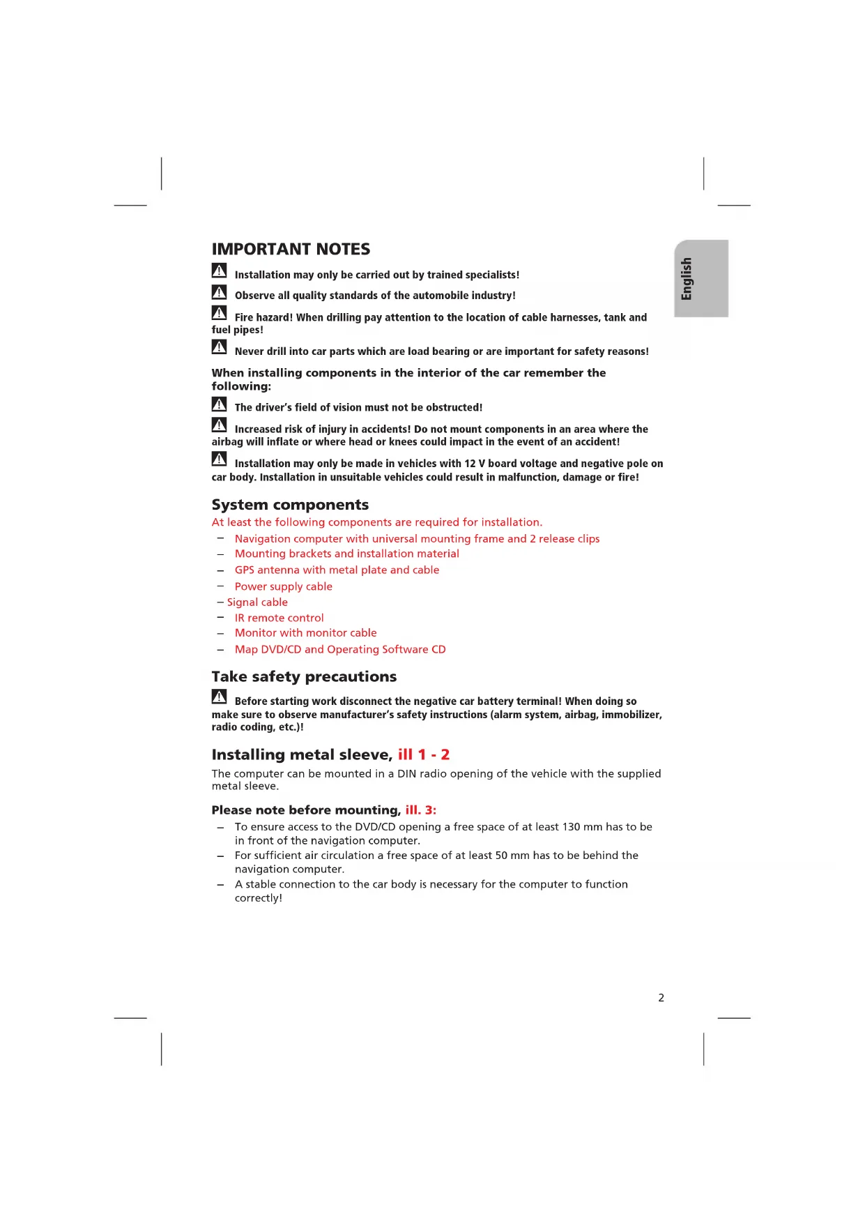
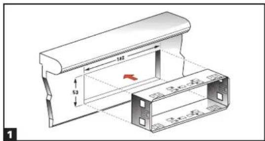
Installing metal sleeve, ill 1 - 2
The computer can be mounted in a DIN radio opening of the vehicle with the supplied metal sleeve.
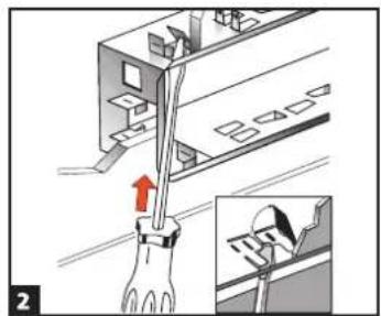
Please note before mounting, ill. 3:
- To ensure access to the DVD/CD opening a free space of at least 130 mm has to be in front of the navigation computer.
- For sufficient air circulation a free space of at least 50 mm has to be behind the navigation computer.
- A stable connection to the car body is necessary for the computer to function correctly!
Horizontal mounting, ill. 3
The navigation computer has to be installed in horizontal position. A deviation of -10 to +30 degrees can be adjusted within the diagnosis menu (see "Initial start-up"). Greater deviations can cause malfunctions.
Insert metal sleeve into the DIN opening and press appropriate tags outwards with a screwdriver. Take care not to damage hidden parts in the dashboard.
Securing the computer using the mounting brackets
If installation of the navigation computer in a DIN slot is impossible or undesirable, it can be installed in alternative installation locations using the supplied mounting brackets (e.g., in the glove box, in the luggage compartment or under the seats).
For this purpose, both side-mounted catch springs must be removed from the navigation computer. The two Torx screws are required later for securing the mounting bracket.
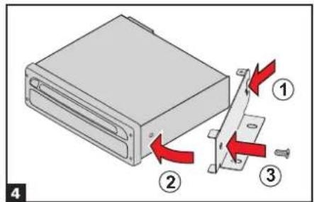
Attaching mounting brackets, ill. 4
- Position the brackets with the punched out tab at the right (or left) rear edge of the computer housing. It must be ensured that the tab fully engages with the sheet metal of the computer housing.
- Swing the bracket forwards, applying pressure to the rear edge of the bracket so that it is flush with the computer housing.
- Fasten the brackets to the computer housing using the existing Torx screws.
The computer can then be secured in the desired installation location using the screws supplied.
Suspended installation
If suspended installation is required for the computer (e.g., under the rear shelf), the mounting brackets can be attached to the computer in the reversed position.
Installing GPS antenna, ill. 6
The GPS antenna can be mounted in the vehicle interior, for example on the dashboard or on the hatshelf. The antenna must have clear "view" of the sky.
- Clean the mounting surface and attach the antenna with the double-sided tape.
- In vehicles with metallic window tinting the GPS antenna should be mounted outside on the vehicle body, for example on the roof or in the plastic bumper.
Notes: To ensure perfect function please keep a distance of at least 10 cm to metal parts like window frame. Mounting temperature should be at least 60 degrees Fahrenheit to ensure the full adhesive effect of the tape.
Mounting monitor
Never install the monitor in an area where the head could impact in case of an accident!
Observe safety standards concerning the driver's field of vision and airbag inflation area!
The monitor can be fastened with a support which is available on the market for accessories.
Depending on the type of monitor (4:3 or 16:9 display) you use you can select the rectification for guidance pictograms. The system is adjusted to a 16:9 display by factory default.
Installing holder for the remote control (optional), ill. 8 - 9
Mounting on angle bracket
Screw holder to angle bracket. Either insert angle bracket into an available slot or screw it in place.
Mounting with adhesive plate
Snap holder onto plastic plate. Remove protective paper from adhesive tape. Stick holder with adhesive plate onto mounting surface and press firmly.
Note: Mounting temperature should be at least 60 degrees Fahrenheit to ensure the full adhesive effect of the tape.
Completing electrical connections, ill. 10
Lay all cables carefully. Refer to the connecting diagram on page 3 and to the table below.
Power supply cable (ISO connector A):
| Pin no. | Cable color Connection | ||
| A1 | black/white | Speedometer signal input, digital (long cable) | ● |
| A2 | white/yellow | Back-up lights (reversing signal) | ● |
| A3 | black/white | Speedometer signal input, analogue (short cable) | ○ |
| A4 | red | +12V permanent power supply - fuse 10 A if necessary | ● |
| A5 | white/blue | Switch input “Accessory” | ○ |
| A6 | grey | Switch input low beam (do not connect to dashboard illumination!) | ● |
| A7 | violet | +12V switched - must not be interrupted during engine start | ● |
| A8 | brown | Negative battery pole | ● |
● = connection required
O= connection optional
Only connect electrical signals to appropriate terminals in the vehicle.
In the case of a direct connection to the battery secure the positive connection (red lead) with a 10 A fuse close to the battery (approx. 10 - 15 cm).
- Connect the free cable ends A4, A7 and A8 of the power supply cable to suitable terminals in the vehicle according to the connecting diagram and the table.
- Do not cut off unused cables! Wind them together and tie them back! They may be used later to install additional features.
Speedometer signal (ISO connector A):
Depending on the type of speedometer signal, either the digital (A1) or the analogue (A3) input must be selected. Check speedometer signal using an oscilloscope if necessary.

Never tap the speedometer signal from the ABS control!
Digital (standard):
Connect the black/white cable A1 from cable harness to the tapping position of the speedometer signal. Location and connection details can be found in the vehicle specific information sheets (available as CD ROM).
Note: Many cars are supplied with the speedometer signal on one of the car radio connectors. Ask your car dealer for more information or call our hotline.
Analogue (for retrofitted speedometer senders and magnetic sensors):
Connect the short black/white A3 cable (directly at ISO chamber A connector) of the wiring harness to the output of the speedometer sensor or the magnetic sensor.
Further signals (ISO connector A):
- Connect the white/yellow cable (A2) to a suitable connecting point of the back up lights (positive pole of the reversing lamp).
- Connect the grey cable (A6) to a suitable connecting point of the low beam (do not connect to dashboard illumination!).
Connecting system components (ISO connector B):
Remote control holder
Connect the plug of the remote control cable to the Mini-DIN socket on the signal cable harness.
Loudspeaker (accessory):
Connect the loudspeaker (ML 5000) with the 3.5 mm jack to the 3.5 mm plug of the signal cable harness.
Multimedia extension (ISO connector C3):
A Multimedia Center can additionally be connected to the navigation computer. For connection details see "Mounting the navigation computer".
Reproduction of voice messages through vehicle speakers
For reproduction of the guidance messages by the left front speaker of the vehicle you can connect an adaptor cable MA 1300 (optional) between the loudspeaker connector and the audio output of the navigation computer.
Mounting the navigation computer
- Connect the GPS antenna.
- Connect power supply cable to ISO connector A' at the navigation computer.
- Connect signal cable to ISO connector B' at the navigation computer.
- Connect monitor cable to the monitor output of the navigation computer.
- If you want to connect system extensions, take care to slide all the C plugs together before connecting them to ISO connector C' at the navigation connector. Middle part (C2) of ISO connector C2,, Blue plug C3 of the Multimedia extension (optional): right chamber of ISO connector C3'.
- Screw the rubber buffer onto the rear support stud of the navigation computer and slide the computer into the metal sleeve until it clicks into position.
Caution: First mount the navigation computer firmly, then make the connection to the vehicle's power supply. Otherwise a wrong calibration of the gyro sensor may result.
Initial start-up
- Reconnect the car battery.
- Restore perfect functioning of the electrical system (clock, onboard computer, alarm system, airbag, immobilizer, radio coding, etc.).
- Switch on the ignition.
- Insert the map DVD/CD into the computer. Please note the instructions on enabling the map DVD/CD in the operating instructions.
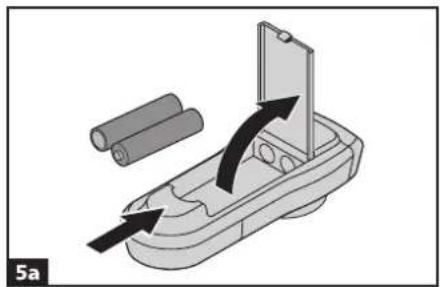
- Insert batteries in the remote control battery compartment, Fig. 5. If a holder (accessory) is being used for the remote control, the remote control also works without batteries.
- Park the car so that the GPS antenna has free "visual contact" to the sky.
- Start the engine. The monitor display appears (user advice).
- Confirm the user advice by pressing OK key on the remote control. The start menu appears, initialization of the navigation computer then begins (duration between 2 and 10 minutes).
Configuring the system
Adjusting mounting angle
- Select "System Information" from the "Setting" menu.
- Select "Diagnosis" from the "System Information" menu. Then enter code number "6330" and confirm.
- Select "Mounting angle" option and adjust angle corresponding to the mounting situation: Permissible mounting angle between -10 to +30 degrees. The system does not differentiate between negative and positive angles. Thus, even for a mounting angle of, e.g. -10 degrees, set a value of "10" in the menu.
Display adjustment 4:3 / 16:9 (factory default)
- Enter "Diagnosis" menu as described above.
- Select "Display" option and select desired setting for the pictogram rectification (4:3 or 16:9 display type).
- If an RGB converter is used the "No sync. in green" option may have to be selected if necessary.
Selecting language for menus and voice messages
ATTENTION: Before loading other languages make sure to load the latest operation software from the CD.
For loading other languages see user manual of the navigation system.
Checking the car functions

Only check safety functions when the car is standing still or driving at low speed! Days carry out checks in open areas!
Check brake system, alarm system, lights, immobilizer, speedometer, trip computer, radio (coding) and hi-fi stereo, clock.
Checking the navigation functions
Check the following functions when the car is stationary:
Remote control (batteries inserted):
Press the buttons on the remote control and watch for the reaction on the navigation system.
Remote control holder
Insert the remote control into the holder (without batteries): The keys on the remote control must light up.
Day time / night time display colours
Switch on low beam. The monitor must change from day time colors to night time colors.
GPS reception
Select "Map" option from the navigation menu. The map with the calculated car position is displayed. As soon as sufficient GPS reception is guaranteed the color of the GPS symbol changes from red to green.
Calibration
Make a short test drive (approx. 10 minutes) on digitized streets for automatic calibration. Change direction several times.
- Drive to an intersection:
The distance indicated on the monitor must be correct. - Drive a short distance in reverse:
The position indicated on the monitor must display the correct driving direction.
Speedometer signal
The functioning of the speedometer signal can be tested using the trip computer function of the navigation system. The trip computer must show the current vehicle speed during driving. The wrong speed may be indicated prior to final calibration.
Hotline
For answers and questions concerning the Navigation System there is a Hotline available in many countries. You can find the hotline numbers and service addresses on a separate sheet.
Subject to technical modifications and errors.
REMARQUES IMPORTANTES

- AUDIOVOX®
- NPD 5500
- NPC 5400
- IMPORTANT NOTES
- System components
- Take safety precautions
- Installing metal sleeve, ill 1 - 2
- Please note before mounting, ill. 3:
- Horizontal mounting, ill. 3
- Securing the computer using the mounting brackets
- Attaching mounting brackets, ill. 4
- Suspended installation
- Installing GPS antenna, ill. 6
- Mounting monitor
- Installing holder for the remote control (optional), ill. 8 - 9
- Mounting on angle bracket
- Mounting with adhesive plate
- Completing electrical connections, ill. 10
- Speedometer signal (ISO connector A):
- Never tap the speedometer signal from the ABS control!
- Digital (standard):
- Analogue (for retrofitted speedometer senders and magnetic sensors):
- Further signals (ISO connector A):
- Connecting system components (ISO connector B):
- Remote control holder
- Loudspeaker (accessory):
- Multimedia extension (ISO connector C3):
- Reproduction of voice messages through vehicle speakers
- Mounting the navigation computer
- Initial start-up
- Configuring the system
- Adjusting mounting angle
- Display adjustment 4:3 / 16:9 (factory default)
- Selecting language for menus and voice messages
- Checking the car functions
- Checking the navigation functions
- Day time / night time display colours
- GPS reception
- Calibration
- Speedometer signal
- Hotline
- REMARQUES IMPORTANTES
Brand : AUDIOVOX
Model : NPD 5500
Category : Browser