
HUZ 5 OKO COMFORT - Boiler AEG - Free user manual and instructions
Find the device manual for free HUZ 5 OKO COMFORT AEG in PDF.
| Product type | Free-flow water heater (zero pressure) |
| Brand | AEG |
| Model | HUZ 5 ÖKO COMFORT |
| Nominal capacity | 5 L |
| Dimensions (W x H x D) | 263 x 443 x 230 mm |
| Weight | 3.2 kg |
| Power supply | 230 V, 1/N/PE, 50/60 Hz |
| Nominal power | 2 kW |
| Nominal current | 8.7 A |
| Electrical protection | 10 A |
| Protection rating (IP) | IP24 D |
| Temperature adjustment range | 35 °C – 85 °C |
| Maximum flow rate | 5 L/min |
| Maximum permissible pressure | 0 MPa (free-flow) |
| Energy efficiency class | A |
| Annual electricity consumption | 487 kWh |
| Main functions | Continuous temperature adjustment, ThermoStop function (thermal insulation), heating indicator |
| Mounting type | Under-sink only |
| Hydraulic connections | Cold water inlet G 3/8 A male, hot water outlet G 3/8 A male |
| Inner tank material | Synthetic material |
| Thermal insulation | EPS |
| Maintenance and cleaning | Clean with a damp cloth, regular descaling of the tap and appliance |
| Safety | Temperature safety limiter, burn protection, automatic shutdown in case of overheating, use by children from 8 years under supervision |
| Spare parts and repairability | Original spare parts required, replacement of power cable by qualified installer |
Frequently Asked Questions - HUZ 5 OKO COMFORT AEG
User questions about HUZ 5 OKO COMFORT AEG
0 question about this device. Answer the ones you know or ask your own.
Ask a new question about this device
Download the instructions for your Boiler in PDF format for free! Find your manual HUZ 5 OKO COMFORT - AEG and take your electronic device back in hand. On this page are published all the documents necessary for the use of your device. HUZ 5 OKO COMFORT by AEG.
USER MANUAL HUZ 5 OKO COMFORT AEG
Open vented (non-pressurised) small water heater Operation and installation ____ 12
Hoz 5 Comfort
26_02_06_0019
1 Temperatur-Einstellknopf
2 Aufheizanzeige
D0000045678
26 02 06 0025
D0000045671
1 Begrenzungsring
2 Temperatur-Einstellknopf
- General information .... 13
- Safety 13
- Appliance description....14
- Cleaning, care and maintenance 14
- Troubleshooting 14
INSTALLATION
- Safety 15
- Appliance description....15
- Preparations....15
- Installation....16
- Commissioning....17
- Settings..... 17
- Shutdown....17
- Troubleshooting 17
- Maintenance....18
- Specification 18
GUARANTEE
ENVIRONMENT AND RECYCLING
INSTALLATION TEMPLATE (IN THE MIDDLE OF THESE INSTRUCTIONS)
SPECIAL INFORMATION
The appliance may be used by children aged 8 and older and persons with reduced physical, sensory or mental capabilities or a lack of experience and know-how, provided that they are supervised or they have been instructed on how to use the appliance safely and have understood the resulting risks. Children must never play with the appliance. Children must never clean the appliance or perform user maintenance unless they are supervised.
- When permanently connected to the power supply using a dedicated junction box, the appliance must be able to be isolated from the mains power supply by an isolator that disconnects all poles with at least 3 mm contact separation.
• The power cable may only be replaced (for example if damaged) by a qualified contractor authorised by the manufacturer, using an original spare part.
- Never connect the appliance via a time switch.
- Secure the appliance as described in chapter "Installation / Installation".
- During heating, expansion water drips from the tap outlet.
- The appliance must only be installed with an open (non-pressurised) tap.
- Never subject the appliance to water pressure.
- The tap outlet has a vent function. Scale build-up can block the outlet and subject the appliance to pressure.
- Never seal the tap outlet.
- Only use special aerators for non-pressurised water heaters.
- Never extend the tap outlet with a hose.
- Drain the appliance as described in chapter "Installation / Maintenance / Draining the appliance".
OPERATION
1. General information
The chapters "Special Information" and "Operation" are intended for both the user and qualified contractors.
The chapter "Installation" is intended for qualified contractors.

Note
Read these instructions carefully before using the appliance and retain them for future reference.
Pass on the instructions to a new user if required.
1.1 Safety instructions
1.1.1 Structure of safety instructions

KEYWORD Type of risk
Here, possible consequences are listed that may result from failure to observe the safety instructions.
» Steps to prevent the risk are listed.
1.1.2 Symbols, type of risk
Symbol Type of risk
 | Injury |
 | Electrocution |
 | Burns(burns, scalding) |
1.1.3 Keywords
| KEYWORD | Meaning |
| DANGER | Failure to observe this information will result in serious injury or death. |
| WARNING | Failure to observe this information may result in serious injury or death. |
| CAUTION | Failure to observe this information may result in non-serious or minor injury. |
1.2 Other symbols in this documentation

Note
General information is identified by the adjacent symbol.
» Read these texts carefully.
Symbol Meaning
| Material losses(appliance damage, consequential losses and environmental pollution) | |
| Appliance disposal |
» This symbol indicates that you have to do something.
The action you need to take is described step by step.
1.3 Units of measurement

Note
All measurements are given in mm unless stated otherwise.
2. Safety
2.1 Intended use
This open vented (non-pressurised) appliance is designed for heating domestic hot water. The appliance can supply one draw-off point.
This appliance is intended for domestic use. It can be used safely by untrained persons. The appliance can also be used in a non-domestic environment, e.g. in a small business, as long as it is used in the same way.
Any other use beyond that described shall be deemed inappropriate. Observation of these instructions and of instructions for any accessories used is also part of the correct use of this appliance.
2.2 General safety instructions

WARNING Burns
During operation, the tap can reach temperatures in excess of 60 °C.
There is a risk of scalding at outlet temperatures in excess of 43^ C.

WARNING Injury
Only a qualified contractor is permitted to remove the temperature selector.

WARNING Injury
The appliance may be used by children aged 8 and older and persons with reduced physical, sensory or mental capabilities or a lack of experience and know-how, provided that they are supervised or they have been instructed on how to use the appliance safely and have understood the resulting risks. Children must never play with the appliance. Children must never clean the appliance or perform user maintenance unless they are supervised.
Where children or persons with limited physical, sensory or mental abilities are allowed to use this appliance, we recommend a permanent temperature limit. A qualified contractor can set this limit.

Material losses
The user should protect the appliance and its tap against frost.

Material losses
Never subject the appliance to water pressure. The tap outlet has a vent function. Scale build-up can block the outlet and subject the appliance to pressure.
» Never seal the tap outlet.
» Only use special aerators for non-pressurised water heaters.
» Never extend the tap outlet with a hose.

Material losses
Connecting the appliance via a time switch will cause an unintentional reset of the high limit safety cut-out.
» Never connect the appliance to the power supply via a time switch.
2.3 Test symbols
See type plate on the appliance.
3. Appliance description
The open vented (non-pressurised) appliance constantly maintains the water content at the pre-selected temperature. During heating, expansion water drips from the tap. The appliance may only be installed with taps for open vented (non-pressurised) water heaters (see chapter "Installation / Appliance description / Required accessories").
thermostop function
The thermostop function (thermal separation) of the Huz 5 ÖKO Comfort prevents the tap becoming hot in standby mode.
3.1 Operation
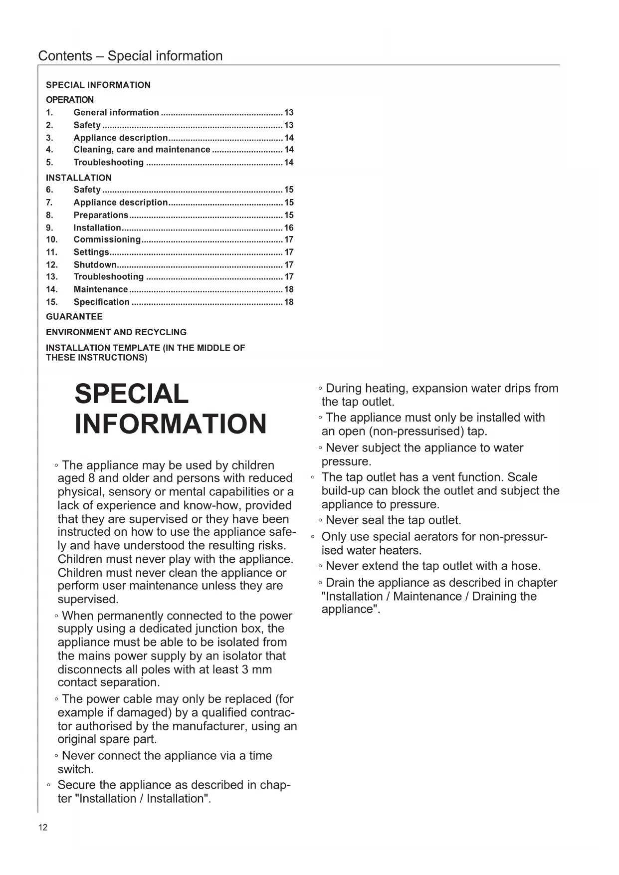
You can set any required DHW outlet temperature at the temperature selector. The heat-up indicator illuminates during the heat-up process.
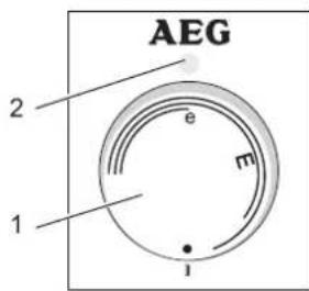
Huz 5 ÖKO Comfort
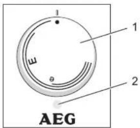
Hoz 5 Comfort
26_02_06_0019
1 Temperature selector
2 Heat-up indicator
Depending on the system, the actual temperatures may vary from the set value.
- Cold. On this setting, the appliance is protected from frost. The tap and the water line are not protected.
E approx. 40 °C
e Recommended energy saving setting (approx. 60 °C), minor scaling

Note
A qualified contractor can set a temperature limit on the appliance (see "Installation / Settings / Setting the temperature limit").
4. Cleaning, care and maintenance
» Never use abrasive or corrosive cleaning agents. A damp cloth is sufficient for cleaning the appliance.
» Check the tap regularly. You can remove limescale deposits at the tap outlet using commercially available descaling agents.
Almost every type of water will deposit limescale at high temperatures. This settles inside the appliance and affects both the performance and service life. The heating elements should therefore be descaled if necessary. A qualified contractor who is aware of the local water quality will tell you when the next descaling is due.
5. Troubleshooting
| Problem | Cause | Remedy |
| The appliance does not supply hot water. | The temperature selector is set to “•”. | Switch the appliance ON by turning the temperature selector. |
| No power at the appliance. | Check the plug / fuses in the fuse box. | |
| Water can only be drawn at a reduced rate. | The aerator in the tap is scaled up. | Descale / replace the aerator. |
| Loud boiling noises inside the appliance. | The appliance is scaled up. | Have the appliance descaled by a qualified contractor. |
If you cannot remedy the fault, notify your contractor. To facilitate and speed up assistance, please provide the numbers from the type plate.
26 02 06 0031
INSTALLATION
6. Safety
Only a qualified contractor should carry out installation, commissioning, maintenance and repair of the appliance.
6.1 General safety instructions
We guarantee trouble-free function and operational reliability only if original accessories and spare parts intended for the appliance are used.
6.2 Instructions, standards and regulations

Note
Observe all applicable national and regional regulations and instructions.
7. Appliance description
The appliance is intended to heat cold water and supply it to a single draw-off point.
Huz 5 ÖKO Comfort
The open vented (non-pressurised) appliance is only suitable for undersink installation.
Hoz 5 Comfort
The open vented (non-pressurised) appliance is suitable only for oversink installation.
7.1 Standard delivery
The following are delivered with the appliance:
- Wall mounting bracket
7.2 Required accessories
The following taps are available as accessories for open vented operation:
Huz 5 ÖKO Comfort
AHEu 50 WT - Mono lever mixer tap for washbasins
AHEu 50 S - Mono lever mixer tap for sinks
AHu 50 - Mixer tap with pivoting spout
AHu 51 - Twin-lever mixer tap with pivoting spout
AHS 50 - Sensor tap
Hoz 5 Comfort
AHo 50 - Twin-lever mixer tap with pivoting spout
8. Preparations
» Flush the water line thoroughly.
Water installation
A safety valve is not required.
Taps/valves
Sealed unvented taps are not permitted.
» Install an open vented tap.
8.1 Installation site

Material losses
Install the appliance in a room free from the risk of frost.

Material losses
Mount the appliance on the wall. The wall must have a sufficient load-bearing capacity.

Note
Ensure that the appliance is freely accessible for maintenance work.
Always install the appliance vertically and near the draw-off point.
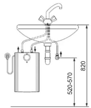
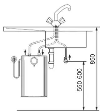
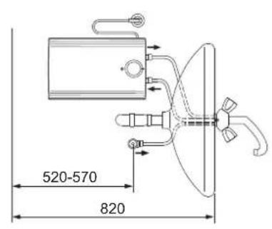
8.1.1 Huz 5 ÖKO Comfort - Undersink installation

Material losses
The Huz 5 ÖKO Comfort is designed exclusively for undersink installation. The water connections of the appliance point upwards.
D0000045680
D0000045679
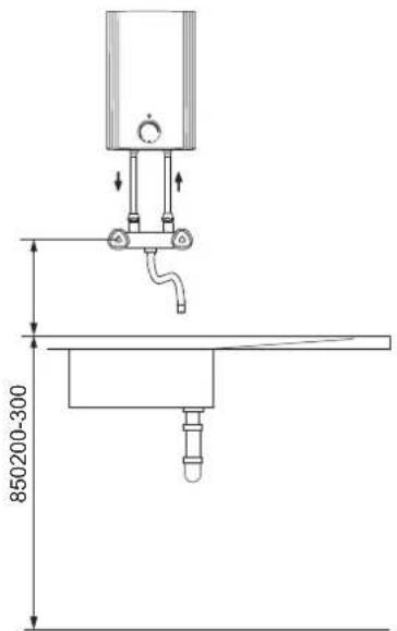
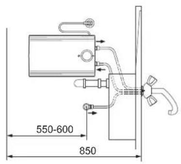
8.1.2 Hoz 5 Comfort - Oversink installation

Material losses
The Hoz 5 Comfort is designed exclusively for over-sink installation. The water connections of the appliance point downwards.
D0000047628

Material losses
Connecting hose length (from tap to appliance) may not exceed 1 m.
For connecting hoses > 1 m:
» Install a tube aerator attachment in the overflow line.
9. Installation
9.1 Appliance installation
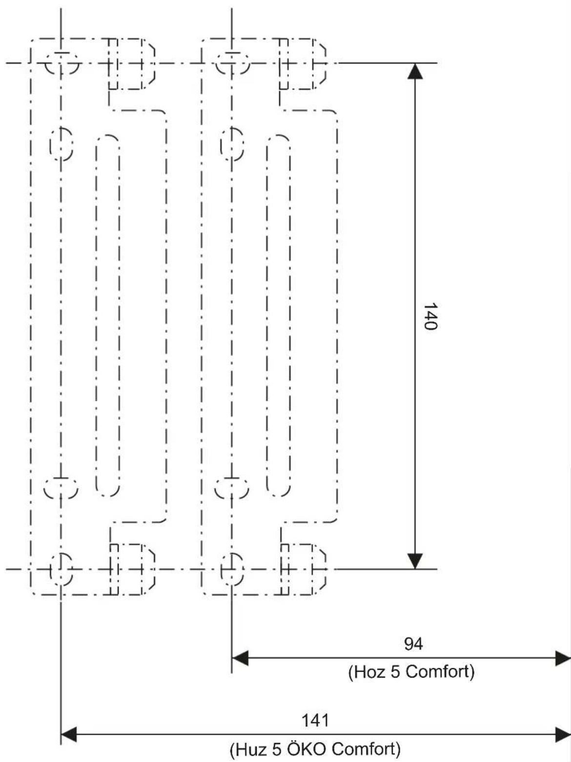
» Mark out the drill holes using the installation template (see middle part of these instructions).
» Drill the holes and insert suitable rawl plugs.
» Secure the wall mounting bracket using suitable screws.
» Hang the appliance on the wall mounting bracket.
9.2 Water connection

Material losses
Carry out all water connection and installation work in accordance with regulations.

Material losses
The appliance may develop a leak and cease functioning.
» Never subject the appliance to water pressure.
» Never interchange the water connections.
» Set the flow rate (see tap instructions). Observe the maximum permissible flow rate with a fully opened tap (see chapter "Installation / Specification / Data table").

Material losses
Counterhold with a suitable spanner when tightening fittings.
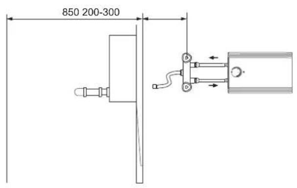
Huz 5 ÖKO Comfort
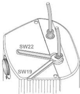
D0000045678
Match up the colour coding on the tap water connections and the appliance:
R.h. side blue = "Cold water inlet"
L.h. side red = "DHW outlet"
» Secure the water connections from the tap to the appliance.

Note
Ensure that the water connections are not kinked during installation. Prevent any tensioning during installation.
Hoz 5 Comfort

26 02 06 0025
» Secure the water connections from the tap to the appliance.

Note
The levers for the twin-lever mixer tap for oversink installation are delivered DIN 44897-compliant:
- Cold water on the left (blue)
Hot water on the right (red)
9.3 Power supply

WARNING Electrocution Carry out all electrical connection and installation work in accordance with relevant regulations.

WARNING Electrocution When permanently connected to the power supply using a dedicated junction box, the appliance must be able to be isolated from the mains power supply by an isolator that disconnects all poles with at least 3 mm contact separation.

WARNING Electrocution Ensure that the appliance is earthed.

Material losses The voltage specified on the type plate must match the mains voltage.
» Observe the type plate.
The following electrical connections are permissible:
| Huz 5 ÖKO Comfort | Hoz 5 Comfort | |
| Connection to a freely accessible standard socket with matching plug | X | X |
| Permanent connection to an appliance junction box with earth conductor | X | X |
10. Commissioning

WARNING Electrocution Commissioning may only be carried out by a qualified contractor in accordance with safety regulations.
10.1 Initial start-up
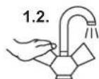
D0000049325
» Either open the DHW valve of the tap or set the mono lever mixer tap to "hot" until the water that flows out is free of air bubbles.
» Insert the plug into the standard socket or set the fuse/MCB in the fuse box.
» Select a temperature.
» Check the entire hydraulic installation for tightness.

Note If you fail to follow the correct sequence (first water, then power), the high limit safety cut-out will trip. Proceed as follows:
» Disconnect the appliance from the power supply.
» Fill the appliance with water.
» Connect the appliance to the power supply.
10.1.1 Appliance handover
» Explain the functions of the appliance to the user. Show the user how to operate the appliance.
» Make the user aware of potential dangers, especially the risk of scalding.
» Hand over these instructions and, if applicable, the instructions for any accessories.
10.2 Recommissioning
See chapter "Installation / Commissioning / Initial start-up".
11. Settings
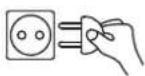
11.1 Setting the temperature limit
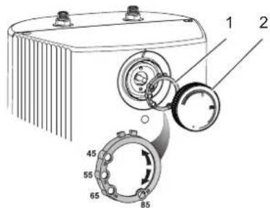
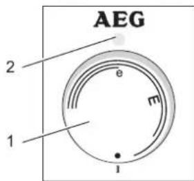
D0000045671
1 Limiting ring
2 Temperature selector
Placing the limiting ring behind the temperature selector allows you to limit the setting range of the temperature selector to a specific maximum temperature.
» Turn the temperature selector to zero (fully anti-clockwise to “•”).
» Pull off the temperature selector and the limiting ring.
» Push the limiting ring with the required maximum setting onto the controller shaft.
» Install the temperature selector set to zero (.)
12. Shutdown
» Isolate the appliance from the power supply by removing the plug or by tripping the MCB in the fuse box.
» Drain the appliance (see chapter "Installation / Maintenance / Draining the appliance").
13. Troubleshooting
| Fault | Cause | Remedy |
| The appliance does not supply hot water. | The high limit safety cut-out has tripped. | Remedy the cause of the fault. If necessary, replace the temperature controller. Allow the appliance to cool down. If you have isolated the appliance from the power supply, the high limit safety cut-out will be reset automatically. |
| Loud boiling noises inside the appliance. | The appliance is scaled up. | Descale the appliance. |
14. Maintenance

WARNING Electrocution
Before any work on the appliance, disconnect all poles of the appliance from the power supply.
» Dismantle the appliance for maintenance work.
14.1 Draining the appliance

WARNING Burns
Hot water may escape during the draining process.
» Drain the appliance via its connectors.
14.2 Opening the appliance
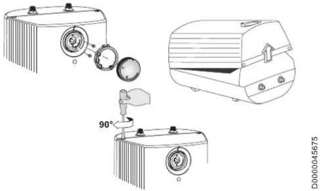
» Pull off the temperature selector and the limiting ring.
» Remove the screws from underneath the temperature selector.
» Open the appliance cover by lowering the bolt screws inwards and pivot the cover upwards, then remove it.
14.3 Descaling the appliance

Material losses
Never treat the cylinder surface with descaling agents.
» Remove the flanged immersion heater.
» Carefully tap the heating element to remove coarse limescale deposits.
» Immerse the heating element up to the flange plate in descaling agent.
14.4 Replacing the power cable
The power cable must only be replaced by a qualified contractor with an original spare part. Alternatively, the H05VV-F3x1.0 cable may be used.
14.5 Checking the earth conductor
» Pull off the temperature selector and the limiting ring.
» Check the earth conductor (in Germany, e.g. BGV A3) across a temperature controller fixing screw and the earth conductor contact of the power cable.
14.6 Positioning the temperature sensor in its protective pipe
» When replacing the temperature controller, guide the temperature sensor into its protective pipe.
» Secure the temperature sensor in place below the earthed plug.
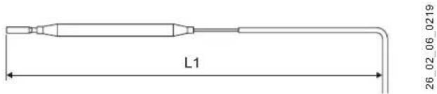
L1 Temperature controller
| Huz 5 ÖKO Comfort | Hoz 5 Comfort | |
| L1 | 185 | 200 |
15. Specification
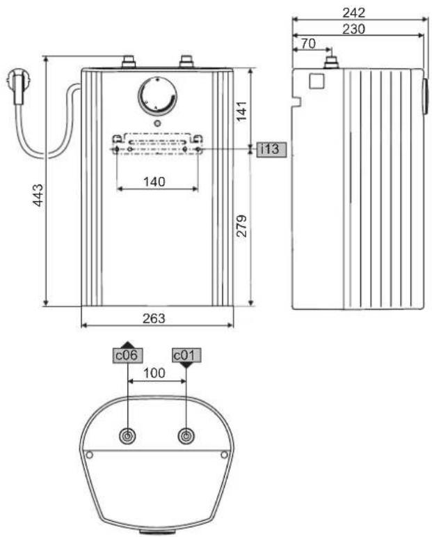
15.1 Dimensions and connections
Huz 5 ÖKO Comfort
D0000018559
| Huz 5 ÖKO Comfort | |||
| c01 | Cold water inlet | Male thread | G 3/8 A |
| c06 | DHW outlet | Male thread | G 3/8 A |
| i13 | Wall mounting bracket | ||
Hoz 5 Comfort
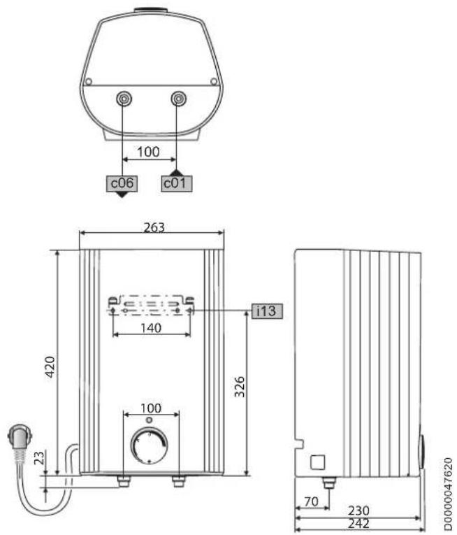
| Hoz 5 Comfort | ||
| c01 Cold water inlet Male thread G 1/2 A | ||
| c06 DHW outlet Male thread G 1/2 A | ||
| i13 Wall mounting bracket |
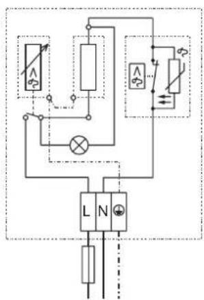
15.2 Wiring diagram
1/N/PE \~ 230 V
flowchart
graph TD
    A["Switch"] --> B["L"]
    A --> C["N"]
    B --> D["Switch"]
    C --> D
    D --> E["Switch"]
    F["Switch"] --> G["Switch"]
    H["Switch"] --> I["Switch"]
    J["Switch"] --> K["Switch"]
    style A fill:#f9f,stroke:#333
    style B fill:#ccf,stroke:#333
    style C fill:#ccf,stroke:#333
    style D fill:#cfc,stroke:#333
    style E fill:#fcc,stroke:#333
    style F fill:#ffc,stroke:#333
    style G fill:#ffc,stroke:#333
    style H fill:#ffc,stroke:#333
    style I fill:#ffc,stroke:#333
    style J fill:#ffc,stroke:#333
    style K fill:#ffc,stroke:#333
85_02_06_0001
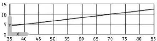
15.3 Heat-up diagram
The heat-up period depends on the degree of scaling and residual heat. For the heat-up time for a cold water supply at 10 °C and a maximum temperature setting, see the diagram.
line
| X | Y | |---|---| | 35 | 4 | | 40 | 5 | | 45 | 6 | | 50 | 7 | | 55 | 8 | | 60 | 9 | | 65 | 10 | | 70 | 11 | | 75 | 12 | | 80 | 13 | | 85 | 14 |D0000047175
x Temperature in °C
y Duration in min
15.4 Country-specific approvals and certifications
The test symbols can be seen on the type plate.
15.5 Extreme operating and fault conditions
In the case of faults, a peak temperature of up to 100 °C may briefly occur in the system.
15.6 Details on energy consumption
Product data complies with EU regulations relating to the Directive on the eco-design of energy related products (ErP).
| Huz 5 ÖKO Comfort | Hoz 5 Comfort | ||
| 222164 | 222154 | ||
| Manufacturer | AEG Haus-technik | AEG Haus-technik | |
| Load profile | XXS | XXS | |
| Energy efficiency class | A | A | |
| Energy conversion efficiency | % | 38 | 38 |
| Annual power consumption | kWh | 487 | 487 |
| Default temperature setting | °C | 55 | 55 |
| Sound power level | dB(A) | 15 | 15 |
| Daily power consumption | kWh | 2,254 | 2,254 |
15.7 Data table
| Huz 5 ÖKOComfort | Hoz 5Comfort | ||
| 222164 | 222154 |
Hydraulic data
| Nominal capacity | 1 | 5 | 5 |
| Mixed water volume at 40 °C | 1 | 10 | 10 |
Electrical data
| Rated voltage | V | 230 | 230 |
| Rated output | kW | 2 | 2 |
| Rated current | A | 8.7 | 8.7 |
| MCB/fuse rating | A | 10 | 10 |
| Phases | 1/N/PE | 1/N/PE | |
| Frequency | Hz | 50/60 | 50/60 |
Application limits
| Temperature setting range | °C | 35-85 | 35-85 |
| Max. permissible pressure | MPa | 0 | 0 |
| Max. flow rate | l/min | 5 | 5 |
Energy data
| Standby energy consumption/24 h at 65 °C | kWh | 0.22 | 0.22 |
| Energy efficiency class | A | A |
Versions
| IP rating | IP24 D | IP24 D | |
| Undersink installation | X | ||
| Oversink installation | X | ||
| Type | Open | Open | |
| Internal cylinder material | Plastic | Plastic | |
| Thermal insulation material | EPS | EPS | |
| Colour | White | White |
Dimensions
| Depth | mm | 230 | 230 |
| Height | mm | 443 | 443 |
| Width | mm | 263 | 263 |
Weights
| Weight | kg | 3.2 | 3.2 |
Guarantee
The guarantee conditions of our German companies do not apply to appliances acquired outside of Germany. In countries where our subsidiaries sell our products a guarantee can only be issued by those subsidiaries. Such guarantee is only granted if the subsidiary has issued its own terms of guarantee. No other guarantee will be granted.
We shall not provide any guarantee for appliances acquired in countries where we have no subsidiary to sell our products. This will not affect warranties issued by any importers.
Environment and recycling
We would ask you to help protect the environment. After use, dispose of the various materials in accordance with national regulations.
other
| Dimension | Value | | --------- | ----- | | (Hoz 5 ÖKO Comfort) | 140 | | (Hoz 5 Comfort) | 94 | | (Huz 5 ÖKO Comfort) | 141 |REMARQUES PARTICULIÈRES
UTILISATION
D0000045678
26_02_06_0025
D0000045671
L1 Thermostat
| Huz 5 ÖKO Comfort | Hoz 5 Comfort | |
| L1 | 185 | 200 |
WAARSCHUWING verbranding
D0000045678
26_02_06_0025
D0000045671
85_02_06_0001
15.3 Opwarmdiagram
Urzhumskaya street 4,
building 2
129343 Moscow
Tel. 0495 7753889
Fax 0495 7753887
Switzerland
STIEBEL ELTRON AG
Industrie West
Gass 8
5242 Lupfig
Tel. 056 4640-500
Fax 056 4640-501

- INSTALLATION
- GUARANTEE
- ENVIRONMENT AND RECYCLING
- INSTALLATION TEMPLATE (IN THE MIDDLE OF THESE INSTRUCTIONS)
- SPECIAL INFORMATION
- OPERATION
- General information
- Safety instructions
- Structure of safety instructions
- Symbols, type of risk
- Keywords
- Other symbols in this documentation
- Units of measurement
- Safety
- Intended use
- General safety instructions
- Test symbols
- Appliance description
- thermostop function
- Operation
- Note
- Cleaning, care and maintenance
- Troubleshooting
- Safety
- General safety instructions
- Instructions, standards and regulations
- Appliance description
- Huz 5 ÖKO Comfort
- Hoz 5 Comfort
- Standard delivery
- Required accessories
- Preparations
- Water installation
- Taps/valves
- Installation site
- Material losses
- Huz 5 ÖKO Comfort - Undersink installation
- Hoz 5 Comfort - Oversink installation
- Installation
- Appliance installation
- Water connection
- Power supply
- Commissioning
- Initial start-up
- Appliance handover
- Recommissioning
- Settings
- Setting the temperature limit
- Shutdown
- Troubleshooting
- Maintenance
- Draining the appliance
- Opening the appliance
- Descaling the appliance
- Replacing the power cable
- Checking the earth conductor
- Positioning the temperature sensor in its protective pipe
- Specification
- Dimensions and connections
- Wiring diagram
- Heat-up diagram
- Country-specific approvals and certifications
- Extreme operating and fault conditions
- Details on energy consumption
- Data table
- REMARQUES PARTICULIÈRES
- UTILISATION
- WAARSCHUWING verbranding
- Opwarmdiagram
- Switzerland
Brand : AEG
Model : HUZ 5 OKO COMFORT
Category : Boiler