MX50D2 EverRun - Outboard motor Tohatsu - Free user manual and instructions
Find the device manual for free MX50D2 EverRun Tohatsu in PDF.


User questions about MX50D2 EverRun Tohatsu
0 question about this device. Answer the ones you know or ask your own.
Ask a new question about this device
Download the instructions for your Outboard motor in PDF format for free! Find your manual MX50D2 EverRun - Tohatsu and take your electronic device back in hand. On this page are published all the documents necessary for the use of your device. MX50D2 EverRun by Tohatsu.
USER MANUAL MX50D2 EverRun Tohatsu
natural_image
Technical line drawing of a multi-blade electric motor or thrush assembly (no text or symbols)
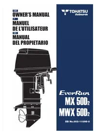
TOHATSU
Outboards
EverRun
MX 50D₂
MWX 50D₂
OB No.003-11098-0
OWNER'S MANUAL
natural_image
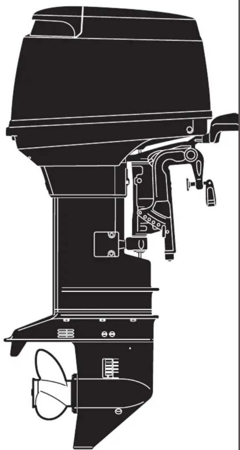
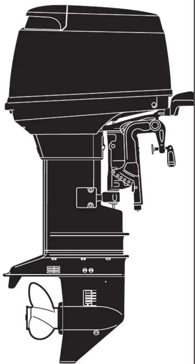
Technical line drawing of a right-hand electric motor (no text or symbols)EverRun
MX 50D₂
MWX 50D₂
OB No.003-11098-0
READ THIS MANUAL BEFORE USING THE OUTBOARD MOTOR. FAILURE TO FOLLOW THE INSTRUCTIONS AND SAFETY PRECAUTIONS IN THIS MANUAL CAN RESULT IN SERIOUS INJURY OR DEATH. KEEP THIS MANUAL IN A SAFE LOCATION FOR FUTURE REFERENCE.
Copyright © 2011 Tohatsu Corporation. All rights reserved. No part of this manual may be reproduced or transmitted in any from or by any means without the express written permission of Tohatsu Corporation.
Upon purchasing this product, be sure that the WARRANTY CARD is correctly and completely filled out and mailed to the addressee noted there on. This WARRANTY CARD identifies you as the legal owner of the product and serves as your warranty registration. TO THE EXTENT PERMITTED BY APPLICABLE LAW, YOUR OUTBOARD MOTOR WILL NOT BE COVERED BY THE APPLICABLE LIMITED WARRANTY, IF THIS PROCEDURE IS NOT FOLLOWED.
PRE-DELIVERY CHECK
Be sure that the product has been checked by an authorized TOHATSU dealer before you take delivery.
Limited Warranty
Please refer to the TOHATSU outboard motor Limited warranty provided to you with this product, the terms and conditions of which, as amended from time to time, are incorporated by reference into the manual.
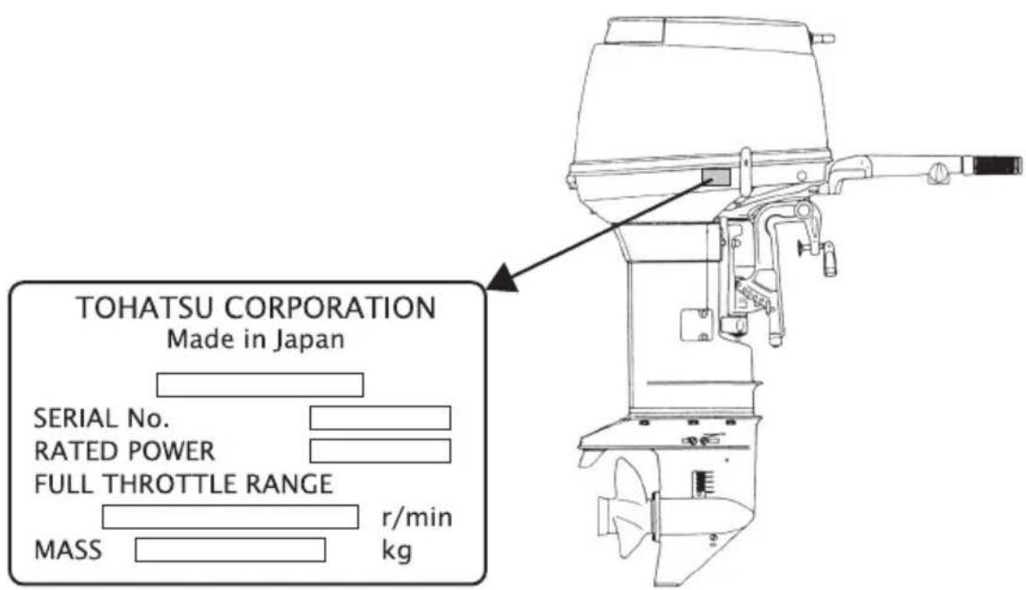
Serial Number
In the space below, please record the outboard motor's serial number (indicated both on the bottom cowl and on the cylinder block). The serial number will be needed in ordering spare parts and the event of theft or to quickly identifying the outboard motor type.
Serial Number :
text_image
TOHATSU CORPORATION Made in Japan SERIAL No. RATED POWER FULL THROTTLE RANGE r/min MASS kgTo You, Our Customer
Thank you for selecting a TOHATSU outboard motor. You are now the proud owner of an excellent outboard motor that will service you for many years to come.
This manual should be read in its entirety and the inspection and maintenance procedures described later in this manual should be followed carefully. Should a problem arise with the outboard motor, please follow the troubleshooting procedures listed at the end of this manual. If the problem persists, contact an authorized TOHATSU service shop or dealer.
We hope you will enjoy your outboard motor and wish you good luck in your boating adventures.
TOHATSU CORPORATION
CONTENTS
GENERAL SAFETY INFORMATION....8
1. SPECIFICATIONS....10
2. NAMES OF PARTS ..... 11
3. INSTALLATION....12
- Mounting the outboard motor on boat 12
- Propeller Selection....14
4. PRE-OPERATING PREPARATIONS .....15
- Recommended gasoline types 15
- Recommended engine oil 17
- Break-in 19
5. ENGINE OPERATION ....20
- Starting....20
- Warming up the engine .....23
- Forward and reverse .....24
- Shallow water running .....26
- Stopping the engine....27
- Trim angle 28
- Mooring with the engine tilted up 30
6. REMOVING AND CARRYING THE OUTBOARD MOTOR....32
- Removing the outboard motor....32
- Carrying the outboard motor 32
- Storing the outboard motor 33
7. TRAILERING ....35
8. ADJUSTMENT....36
- Trim tab adjustment....36
- Steering load adjustment....37
- Throttle grip turning load adjustment....38
9. INSPECTION AND MAINTENANCE....39
- Daily inspection ....40
- Periodic inspection ....44
- Off-season storage .....49
- Pre-season check ....50
- Checking after striking underwater object....51
- If the engine becomes submerged in water....51
- Precautions in cold weather....52
10. TROUBLESHOOTING....53
11. TOOL KIT AND SPARE PARTS .....55
12. OPTIONAL ACCESSORIES .....56
13. PROPELLER TABLE .....57
14. WIRING DIAGRAM ....58
INDEX
GENERAL SAFETY INFORMATION
- SPECIFICATIONS
- NAMES OF PARTS 2
- INSTALLATION 3
- PRE-OPERATING PREPARATIONS 4
- ENGINE OPERATION 5
- REMOVING AND CARRYING THE OUTBOARD MOTOR 6
- TRAILERING 7
- ADJUSTMENT 8
- INSPECTION AND MAINTENANCE 9
- TROUBLESHOOTING 10
- TOOL KIT AND SPARE PARTS
- OPTIONAL ACCESSORIES 12
- PROPELLER TABLE 13
- WIRING DIAGRAM 14
GENERAL SAFETY INFORMATION
NOTICE : DANGER/WARNING/CAUTION/Note
Before installing, operating or otherwise handling your outboard motor, be sure to thoroughly read and understand this Owner's Manual and carefully follow all of the instructions. Of particular importance is information preceded by the words "DANGER," "WARNING," "CAUTION," and "Note." Always pay special attention to such information to ensure safe operation of the outboard motor at all times.

DANGER
Failure to observe will result in severe personal injury or death, and possibly property damage.

WARNING
Failure to observe could result in severe personal injury or death, or property damage.

CAUTION
Failure to observe could result in personal injury or property damage.
Note
This instruction provides special information to facilitate the use or maintenance of the outboard motor or to clarify important points.
EMERGENCY STOP SWITCH
The Emergency Stop Switch will stall the outboard motor when the stop switch tether is pulled off. This stop switch tether can be attached to the operator of the outboard motor to minimize or prevent injuries from the propeller in case the operator falls overboard.
We highly recommend use of the Emergency Stop Switch tether.

WARNING
Accidental activation of the Emergency Stop Switch (such as the tether being pulled out in heavy seas) could cause passengers to lose their balance and even fall overboard, or it could result in loss of power in heavy seas, strong currents, or high winds. Loss of control while mooring is another potential hazard.
To minimize accidental activation of the Emergency Stop Switch, the 500 mm (20 inch.) stop switch tether is coiled and can extended to a full 1,300 mm (51 inch.).
As the operator/driver of the boat, you are responsible for the safety of those aboard and those in other boat around yours, and for following local boating regulations. You should be thoroughly knowledgeable on how to correctly operate the boat, outboard motor, and accessories. To learn about the correct operation and maintenance of the outboard motor, please read through this manual carefully.
It is very difficult for a person standing or floating in the water to take evasive action should he or she see a power boat heading in his /her direction, even at a slow speed. Therefore, when your boat is in the immediate vicinity of people in the water, the outboard motor should be shifted to neutral and shut off.

WARNING
SERIOUS INJURY IS LIKELY IF A PERSON IN THE WATER MAKES CONTACT WITH A MOVING BOAT, GEAR HOUSING, PROPELLER, OR ANY SOLID DEVICE RIGIDLY ATTACHED TO A BOAT OR GEAR HOUSING.
SERVICING, REPLACEMENT PARTS & LUBRICANTS
We recommend that only an authorized service shop perform service or maintenance on this outboard motor. Be sure to use genuine parts, genuine lubricants, or recommended lubricants.
MAINTENANCE
As the owner of this outboard motor, you should be acquainted with correct maintenance procedures. It is the operator's responsibility to perform all safety checks and to ensure that all lubrication and maintenance instructions are complied with for safe operation. Please comply with all instructions concerning lubrication and maintenance. You should take the engine to an authorized dealer or service shop for periodic inspection at the prescribed intervals.
Correct periodic maintenance and proper care of this outboard motor will reduce the chance of problems and limit overall operating expenses.
MOUNTING
Outboard motor mounting must be performed by trained service person(s) using lift or hoist with sufficient capacity.
X50D2MF, WX50D2MF
| Item MODEL | X50D2MF WX50D2MF | ||
| Overall Length mm (in) 1,143 (45.0) 1,145 (45.1) | |||
| Overall Width mm (in) 384 (15.1) 384 (15.1) | |||
| Overall Height | S mm (in) 1,225 (48.2) - | ||
| L mm (in) 1,352 (53.2) 1,413 (55.6) | |||
| LL mm (in) 1,427 (56.1) - | |||
| UL mm (in) 1,479 (58.2) - | |||
| Transom Height | S mm (in) 403 (15.9) - | ||
| L mm (in) 530 (20.9) 550 (21.7) | |||
| LL mm (in) 570 (22.5) - | |||
| UL mm (in) 657 (25.9) - | |||
| Weight | S kg (lb) 72 (159) - | ||
| L kg (lb) 73.5 (162) | 79 (174) | ||
| LL kg (lb) 74 (163) - | |||
| UL kg (lb) 75 (165) - | |||
| Output kW (Hp) | 36.8 (50) | ||
| Max. Operating Range rpm | 5,150-5,850 | ||
| Number of Cylinders | 3 | ||
| Piston Displacement mL (Cu in) | 697 (42.53) | ||
| Bore x Stroke mm (in) | 68 x 64 (2.68 x 2.52) | ||
| Exhaust System | Through hub exhaust | ||
| Engine Lubrication | Premixed Fuel | ||
| Fuel mixing Ratio | 50 : 1 | ||
| Cooling System | Forced water cooling | ||
| Starting System | Manual | ||
| Ignition System | Flywheel Magneto C.D. Ignition | ||
| Spark Plugs | NGK B8HS-10 | ||
| Trim Position | 6 | ||
| Engine Oil | Genuine Motor Oil or recommended one (TCW-III) | ||
| Gear Oil* | approx. 500mL | approx. 700mL | |
| Fuel Tank Capacity L (US gal) | 25 (6.6) | ||
| Engine Oil Capacity L (US gal) | - | ||
| Gear Reduction Ratio | 1.85 (13 : 24) | 1.92 (12 : 23) | |
| Fuel | Unleaded regular gasoline pump posted 87 Octane (research octane rating of 91) | ||
* Genuine Gear Oil or API GL5, SAE #80 to #90
Remark: This specifications might change without a previous notice.
■ NAMES OF PARTS
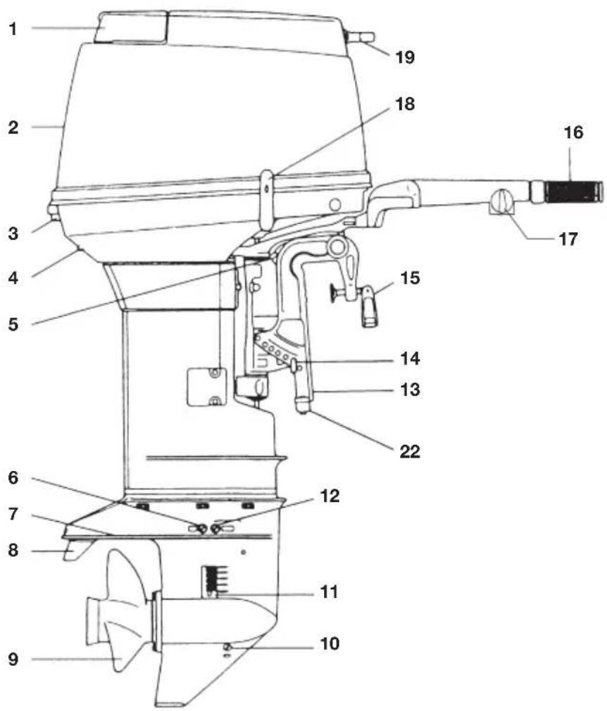
X50D2MF, WX50D2MF
text_image
Technical diagram of an electric motor with numbered parts for identification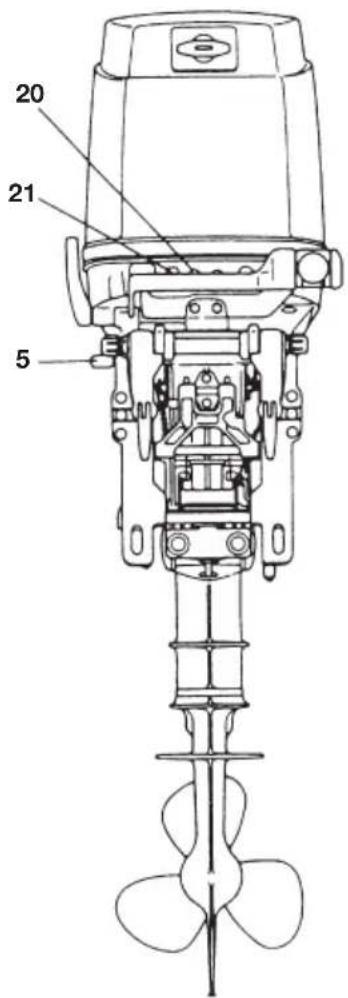
text_image
20 21 51 Tilt Handle
2 Top Cowl
3 Hook Lever
4 Water Check Port
5 Reverse Lock Lever
6 Water Plug
7 Anti-ventilation Plate
8 Trim Tab
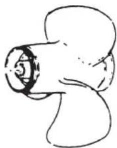
9 Propeller
10 Oil Plug (lower)
11 Water Strainer
12 Oil Plug (upper)
13 Clamp Bracket
14 Thrust Rod
15 Clamp Screw
16 Throttle Grip
17 Adjust Nut
18 Shift Lever
19 Starter Handle
20 Stop Switch
21 Choke Knob
22 Anode
INSTALLATION
1. Mounting the outboard motor on boat

WARNING
Most boats are rated and certified in terms of their maximum allowable horsepower, as shown on the boat's certification plate. Do not equip your boat with an outboard motor that exceeds this limit. If in doubt, contact your dealer.
Do not operate the outboard motor until it has been securely mounted on the boat in accordance with the instructions below.
Note
Consult your authorized dealer to receive the proper instructions or ask your dealer to mount the motor as necessary.
Installation
■ Single-engine Installation
Position the outboard engine at the exact center of the stern, and mount it using a cushioning pad or plate.
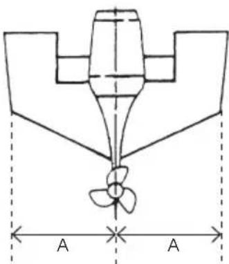
text_image
A A■ Twin-engine Installation
When installing two outboard engines, be sure to keep an interval of approximately 470 - 660 mm (18.5 - 26 in) between the two.
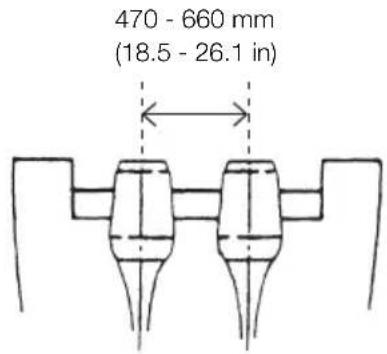
text_image
470 - 660 mm (18.5 - 26.1 in)
CAUTION
- Before beginning the running test, check that the boat with maximum capacity loading floats on the water in a proper attitude. Check the position of water surface on the driveshaft housing. If the water surface is near the bottom cowling, in high waves, water may enter the engine cylinders.
- Incorrect outboard motor mounting height or existence of underwater object(s), such as hull bottom design, bottom surface conditions or underwater accessories, can cause water spray possibly reaching the engine through an opening of the bottom cowling during cruising. Exposing engine to such conditions for extended periods can lead to severe engine damage.
■ Transom Height
Install the engine with the Anti-ventilation Plate at a level 10\~30mm (0.4\~1.2in.) below the bottom of the boat.
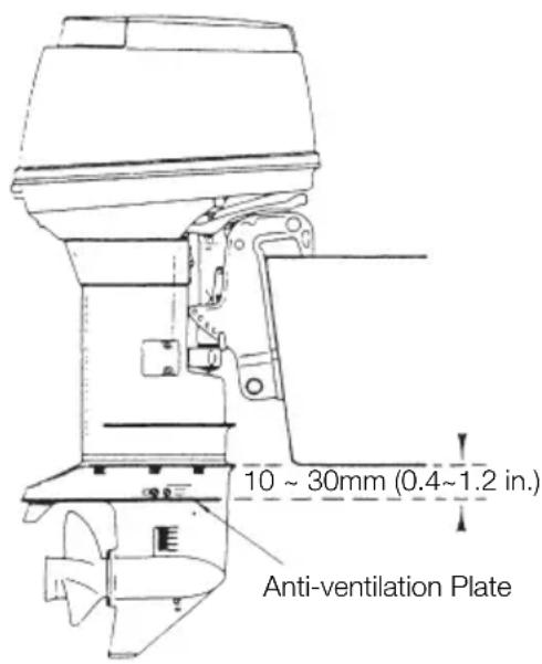
text_image
10 ~ 30mm (0.4~1.2 in.) Anti-ventilation Plate■ Transom Matching
Be sure that anti ventilation plate of the outboard is below the water surface when running with wide open throttle.
In case the above condition cannot be met due to the shape of your boat, please consult your authorized dealer.

CAUTION
Overheating may occur if the Anti-ventilation Plate is at a level higher than the bottom of the boat, as a result of a lack of cooling water.
If the height difference exceeds 10\~30mm (0.4\~1.2 in) engine power performance is likely to be reduced as a result of increased water resistance to the gear case assembly.
■ Attaching the Clamp Bracket
After positioning the Clamp Bracket, fix it with clamp screw then drill four holes in the transom board, matching the holes in the Clamp Bracket. Secure the engine with the supplied bolts (M12 x 105mm) and nuts. Be sure to use the washers. Use the larger diameter washers inside of the transom board and use the small diameter washers outside of the clamp bracket.
The mounting holes may be drilled beforehand by referring to the dimensional drawing.

WARNING
- Mounting the outboard motor without following this manual can lead to unsafe conditions such as poor maneuverability, going out of control or fire disaster.
- Loose clamp screws and/or mounting bolts can lead to the release or displacement of the outboard motor, possibly resulting in lost of control and/or serious personal injury. Be sure that fasteners are tightened to the specified torque (30 Nm (3.0kgf) 13ft·lb). Check the fasteners for tightness from time to time.
- Be sure to use outboard mounting fasteners included in the outboard motor package or their equivalents in terms of size, material, quality and strength.
Tighten fasteners to the specified torque (30 Nm (3.0kgf) 13ft·lb). Test cruise to check if fasteners are tightened securely.
- Outboard motor mounting must be performed by trained service person(s) using lift or hoist with sufficient capacity.
Clamp Bracket Dimensional Drawing
■ Manual tilting type
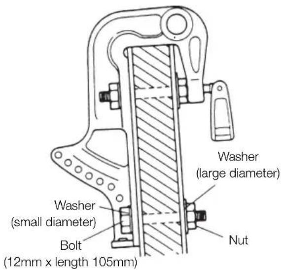
text_image
Washer (large diameter) Washer (small diameter) Bolt (12mm x length 105mm) Nut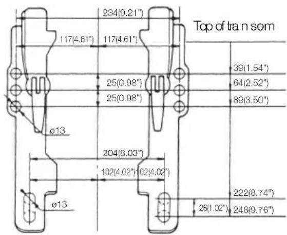
text_image
Top of tran som 234(9.21") 117(4.61") 117(4.61") 25(0.98") 25(0.98") 39(1.54") 64(2.52") 89(3.50") ø13 204(8.03") 102(4.02") 102(4.02") ø13 222(8.74") 26(1.02") 248(9.76)
CAUTION
Mounting bolts should be installed with the bolt head at inside surface of the transom. Mounting bolts installed with the threaded end at the inside surface of the transom can cause personal injury.
2. Propeller Selection
A propeller must be selected so that the engine rpm measured at wide open throttle while cruising is within the max. operating range; 5,150 to 5,850 rpm
For genuine propellers, refer to PROPELLER TABLE (p. 57).
PRE-OPERATING PREPARATIONS

DANGER
Consult an authorized dealer for details on handling of gasoline, if necessary.
Gasoline and its vapors are very flammable and can be explosive.
When carrying a fuel tank containing gasoline:
- Close the air vent screw of fuel tank cap, or gasoline vapor will be emitted through the air vent screw, creating a fire hazard.
- Do not smoke.
When or before refueling :
- Stop the engine, and do not start the engine during refueling.
- Do not smoke.
- Be careful not to overfill fuel tank. Wipe up any spilled gasoline immediately.
When or before cleaning the gasoline tank :
- Dismount fuel tank from the boat.
- Place the fuel tank away from every source of ignition, such as sparks or open flames.
- Do the work outdoors or in well ventilated area.
- Wipe up any spilled gasoline immediately.
After cleaning gasoline tank :
- Wipe up any spilled gasoline immediately.
- If the fuel tank is disassembled for cleaning, reassemble carefully. Imperfect assembly may cause a fuel leak, possibly leading to fire or explosion.
- Dispose of aged or contaminated gasoline in accordance with local regulations.
1. Recommended gasoline types

CAUTION
Use of low-quality gasoline results in a short engine life as well as starting difficulties and other engine problems.
We recommend use for Fuel stabilizer.
Use of unleaded gasoline
Use a major brand of automotive unleaded gasoline with a minimum posted octane rating of 91RON. Automotive gasoline that contain fuel injector cleaner are preferred for added internal engine cleanliness. Leaded gasoline is acceptable in areas where unleaded gasoline is not available.
Use of alcohol free gasoline

CAUTION
Use of gasoline containing alcohol can cause engine starting and/or operating difficulties, wear of and damages to engine parts, and deterioration of chemical parts, which may lead to shortening of your outboard motor's life.
Note
The adverse effect caused by the alcohol content is more severe with methanol than with ethanol.
TOHATSU recommend the use of gasoline if its ethanol content is less than 10% or methanol content is less than 5%, only in case alcohol free gasoline is not available.
The alcohol component of the gasoline absorbs moisture from the air, which may disturb regular fuel flow in the fuel system, and also accelerate rusting of engine parts.
Mixing of the moisture in the engine oil can also deteriorate the properties of the lubricant.
If the use of gasoline containing alcohol is inevitable, or presence of alcohol is suspected in the gasoline, it is strongly recommended to add a filter that has water separating capability, and check the fuel system for leaks and mechanical parts for corrosion and abnormal wear more frequently.
And, in case any of such abnormality is found, discontinue the use of such gasoline and contact our dealer immediately.
Damages resulting from the use of gaso-lines that contain alcohol are not covered under the limited warranty.
Fuel tank capacity : 25 liters (6.6 U.S. gal)
Fuel Tank : When using a fixed fuel tank in place of genuine fuel tank, it is recommended to select a one with a structure facilitating interior cleaning.

WARNING
Do not fill the fuel tank over capacity. The rise of gasoline temperature may cause gasoline to expand which, if overfilled, may leak through air vent screw when it is open. Leaking gasoline is a dangerous fire hazard.
2. Recommended engine oil
Use a genuine engine oil or recommended one (TCW3). Refer to your Distributor.
Will not recommend use of other two stroke engine oil.

CAUTION
Do not mix different brands of oil.
Mixing different brands of oil, or different types of oil even if the brand is the same, may cause gelling, resulting in possible filter screen blockage. This could result in serious engine damage because of impaired lubrication performance.
Note
Use of engine oils that do not meet these requirements will result in reduced engine life, and other engine problems.
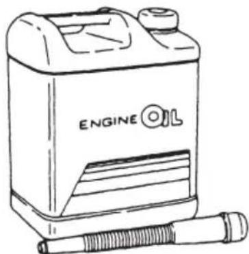
Add engine oil into fuel oil tank. The mixing ratio with gasoline is 1:50 (one part oil and 50 parts gasoline). Mix well by hand. The mixing ratio during break-in running is 1:25.
Mixing Ratio
| Engine Oil : Gasoline | |
| During break-in 1 : | 25 |
| After break-in 1 : | 50 |
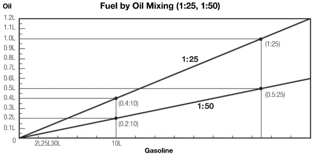
line
| Gasoline | 1:25 Oil (L) | 1:50 Oil (L) | | -------- | ------------ | ------------ | | 2L | 0 | 0 | | 30L | 0.4 | 0.2 | | 10L | 1.0 | 0.5 |Engine oil – gasoline mixing procedure
For quantities of engine oil and gasoline to be pre-mixed, refer to table in Recommended engine oil (p. 17).

CAUTION
- Do not use other than two stroke engine oil with specified grade, or the engine may be damaged.
- Do not use fuel prepared in other than specified mixing ratio.
- Lack of engine oil can cause severe engine trouble such as piston seizure.
- Excess of engine oil can shorten spark plug life, and/or cause increase of noxious exhaust.
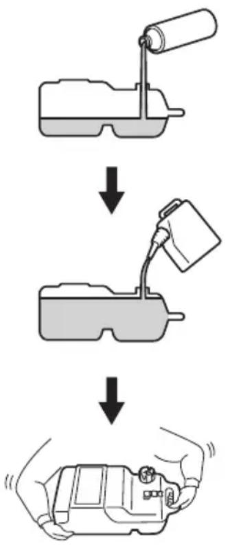
■ When portable fuel tank is used for operation of outboard motor(s):
1 Pour engine oil into fuel tank, and then, gasoline.
2 Put cap on the tank, and close tightly.
3 Close air vent plug tightly.

WARNING
Loose cap or air vent plug can cause leak of fuel during shaking the tank.
4 Shake the tank to mix engine oil and gasoline well and even.
■ When fuel tank built in the boat is used for operation of outboard motor(s):
1 Prepare separate fuel container for pre-mixing.
flowchart
graph TD
    A["Device Injection"] --> B["Patient Inpatient"]
    B --> C["Device Discharge"]
    C --> D["Patient Acute"]
    style A fill:#f9f,stroke:#333
    style B fill:#ccf,stroke:#333
    style C fill:#cfc,stroke:#333
    style D fill:#fcc,stroke:#333
2 Pour engine oil into fuel container, and then, gasoline.
3 Put cap on the container, and close tightly.
4 Shake the container to mix engine oil and gasoline well and even.
5 Pour the mixture into fuel tank.
Notes
- It is recommended to pre-mix by using separate fuel container. Attempting to pre-mix in the fuel tank built-in the boat can make the mixture uneven.
- If built-in fuel tank is used for mixing, pour engine oil into the tank little by little while putting gasoline into the tank.
3. Break-in
Your new outboard motor and lower unit require break-in for the moving components according to the conditions described in the following time table.
CAUTION
Operating the outboard motor without break-in can shorten service life of the product.
If any abnormality is experienced during the break-in:
● Discontinue the operation immediately.
- Have the dealer check the product and take proper action(s) if necessary.
| 1-10min | 10min-2hrs | 2-3hrs | 3-10hrs | After 10hrs | |
| Throttle Position | Idle | Less than 1/2 throttle | Less than 3/4 throttle | 3/4 throttle | Full throttle available |
| Speed | Approx. 3,000 rpm max | Full throttle run allowed for 1 min every 10 min | Approx. 4,000 rpm.Full throttle run allowed for 2 min every 10 min |
Note
Proper break-in allows outboard motor to deliver it full performance for longer service life.
Fuel mix ratio for break-in
Gasoline 25: Genuine Engine Oil 1
● 25:1 when using genuine engine oil or the recommended one (TCW3).
DANGER
Do not operate the outboard motor in closed area or area with no forced ventilation.
Exhaust gas emitted by this outboard motor contains carbon monoxide that will cause death if inhaled continuously. Inhaling the gas initially causes symptoms such as feeling of sickness, drowsiness and headache.
During operation of the outboard motor :
- Keep peripheral area well ventilated.
● Always attempt to stay on the windward side of emission.
ENGINE OPERATION
1. Starting

WARNING
In case engine starts in gear, do not start cruising. Stop engine immediately and consult an authorized dealer.
Note
The engine will not start unless the switch lock has been properly connected into the emergency stop switch.

WARNING
Do not operate the engine with gear case out of water.
Severe personal injury, or engine damage will result.

CAUTION
Never fill up portable fuel tanks on board to avoid fire or explosion resulting from spilled gasoline. If gasoline is ever spilled on board, wipe it up thoroughly. Fuel tanks must always be filled up on land.
Preparations
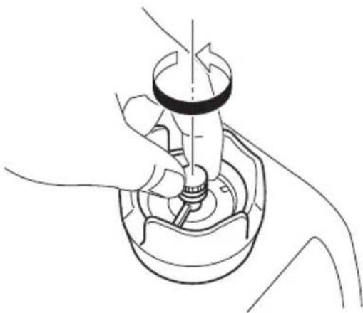
1 Loosen the air vent screw on the tank cap.
natural_image
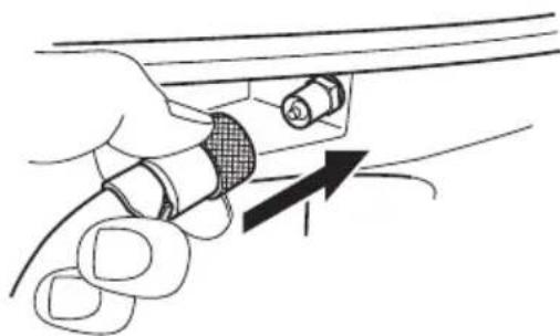
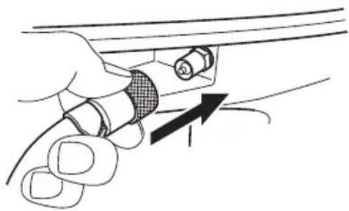
Line drawing of a hand operating a mechanical component with a central shaft and base (no text or symbols)2 Connect the fuel connector to the engine.
natural_image
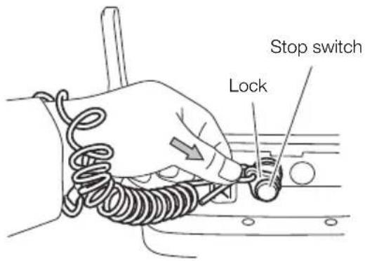
Hand holding a cable with a knob and arrow indicating direction (no text or symbols)3 Install a lock in the stop switch.
text_image
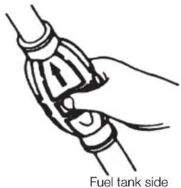
Stop switch Lock4 Feed fuel to the carburetor by squeezing the primer bulb until firm.
Engine side
natural_image
Illustration of a hand gripping a fuel tank side, showing mechanical components and motion (no text or symbols)Starting
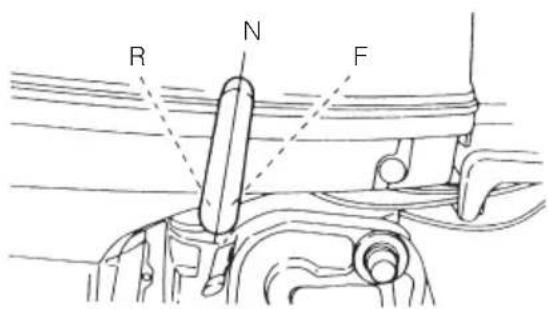
■ F type
1 Set the shift lever to Neutral

CAUTION
If the engine starts in gear, do not use it. Contact an authorized dealer.
Note
Start-in-gear protection prevents engine from starting at other than neutral shift. In-gear starting of engine will move the boat immediately, potentially leading to falling down or causing passenger(s) to be thrown overboard due to inertial force.
text_image
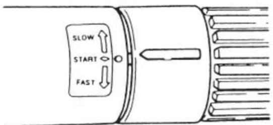
R N F2 Turn the throttle grip so that the indicator line meets the "START" mark.
text_image
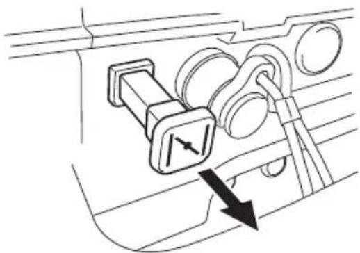
SLOW START FAST3 Pull the choke knob fully.
natural_image
Technical line drawing of a car interior showing a bracket and gear mechanism with directional arrows (no text or symbols)Note
Operation of the choke knob is not required if the engine is warm.
4 Pull the starter rope slowly until resistance is met.
Give it a sharp tug to start the engine.
natural_image
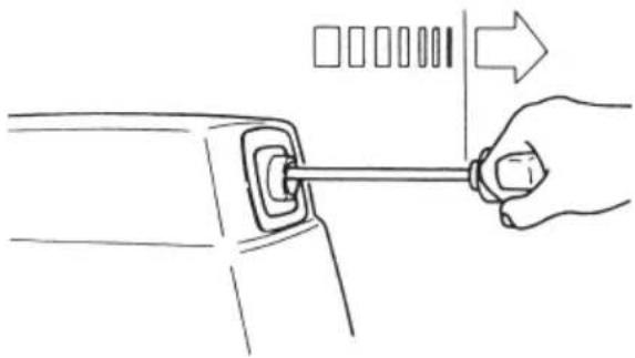
Line drawing of a hand inserting a plug into a device (no text or symbols)5 Turn the handle grip to its original position gradually once the engine has started.
6 Push back the choke knob slowly.
7 Carefully turn the throttle grip to "SLOW".

WARNING
Do not operate the engine with gear case out of water.
Severe personal injury, or engine damage will result.
Manual Rope Start - - - in case of trouble with the Recoil Starter
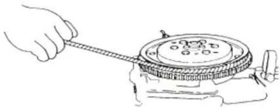
Wind the starter rope around the flywheel a few turns. Give it a sharp tug to start the engine. Use a socket wrench or similar to get a firm grip on the end of the rope.
natural_image
Line drawing of a hand using a tool to lift a mechanical component (no text or symbols)
WARNING
Be careful that your clothes or other items do not get caught in the rotating engine parts.
To prevent accident and injury, do not re-attach the recoil starter after the engine has been started using the emergency starter rope. Be sure to put the top cowl back on.
Immediately contact an authorized dealer when reaching shore.

WARNING
- Be sure that no bystander(s) is within 2 meters from back of starting operator.
- Do not operate the outboard motor with top cowl removed from the power unit, or contacting turning flywheel which can lead to serious personal injury.
2. Warming up the engine
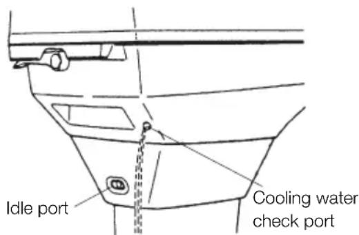
Before driving the boat, let the engine run at low speed for approximately three minutes to let it warm and allow the oil to circulate through the machine. If the engine is not warmed up beforehand, the engine life will shorten greatly. During the warm-up operation, confirm that cooling water is discharged from the check port and idle port.
text_image
Idle port Cooling water check port
CAUTION
Be sure to warm up engine well before starting cruise. Operating cold engine can give damage to it.
Note
Idle speed may be higher during warming up of engine. If shifted to Forward or reverse during warming up, it may be difficult to shift back to neutral. In such case, stop engine, shift to neutral, and restart engine to warm up.

CAUTION
Be sure to stop engine immediately if cooling water check port is not discharging water, and check if cooling water intake is blocked. Operating engine could lead to overheating potentially leading to engine damage. Consult an authorized dealer if the cause cannot be found.
■ Engine speed
Proper idle speed after warm-up operation.
| Clutch in (In gear) Clutch off (Out of gear) | |
| 750rpm 900rpm | |

CAUTION
Do not shift to "F" or "R" until turning into proper idle speed.
Do not exceed the full-throttle engine speed.
| Wide-open throttle rpm range |
| 50D2 : 5,150 - 5,850rpm |
3. Forward and reverse

WARNING
Before shifting into forward or reverse, make sure that boat is properly moored and outboard motor can be steered fully to the right and left. Make sure that no swimmer(s) is ahead or astern of the boat.

WARNING
- Attach other end of emergency stop switch tether to the operator's clothing or arm and keep it attached during cruising.
- Do not attach the tether to a part of clothing that can be torn easily when pulled.
- Arrange the tether so that will not be caught by any object when pulled.
- Be careful not to pull the tether accidentally during cruising. Unintentional stop of engine can cause loss of control of outboard motor. Rapid loss of engine power can lead to falling down or causing passenger(s) to be thrown over board.

WARNING
Be sure to connect the emergency tethered stop hook to your waist or clothing.
The engine will shut down when the switch lock becomes disconnected from the engine.
Note
Do not increase engine speed unnecessarily in reverse.
F type
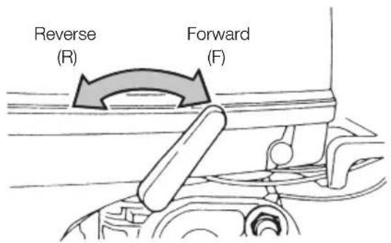
Turn the throttle grip toward "SLOW" and move the Shift Lever quickly to Forward or Reverse when the engine speed has reached the lowest rpm.
text_image
Reverse (R) Forward (F)
WARNING
Severe damage, and personal injury, may occur if shifting at high engine speed.
Engine must be in the slow idle position before shifting is attempted.

WARNING
Before shifting, make sure that no swimmer(s) or obstacle(s) is ahead or astern of the boat.

CAUTION
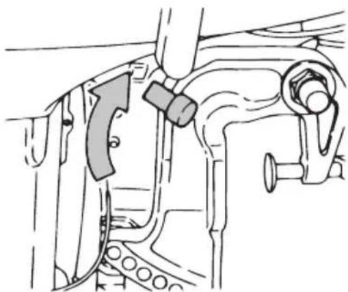
- Before moving the Shift Lever to Reverse, make sure the Reverse Lock is engaged (in up position).
natural_image
Technical diagram of a mechanical assembly with no visible text or symbols- Do not increase the engine speed unnecessarily while reversing.
- The Shift Lever cannot be turned from Neutral to Reverse unless the throttle grip has been turned fully toward "SLOW".
Note
Frequent shifting to forward or reverse can accelerate wear or degradation of parts. In such case, replace gear oil earlier than the period specified.
4. Shallow water running

WARNING
During shallow water operation, be careful not to place your hand between the swivel bracket and the stern bracket.
Be sure to tilt the outboard down slowly.
Note
Slow down to trolling speed, and shift into neutral before setting outboard motor to shallow water drive position.

WARNING
- Run at lowest possible speed during cruising using shallow water drive.
- Tilt lock is disabled when in shallow water drive position.
- When driving shallow water, be careful not to strike outboard motor against sea bottom, or propeller may be pushed out of water, resulting in loss of control.

CAUTION
While in shallow water drive position, do not operate the outboard in reverse. Operate the outboard at slow speed and keep the cooling water intake submerged.
F type
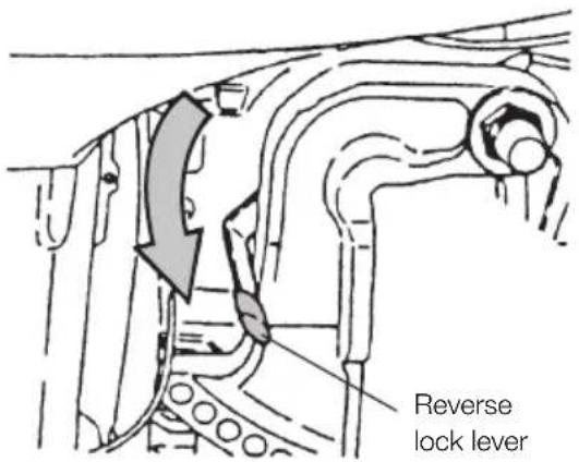
1 Set the Reverse Lock Lever provided on the starboard side to "Release" by turning it downward.
text_image
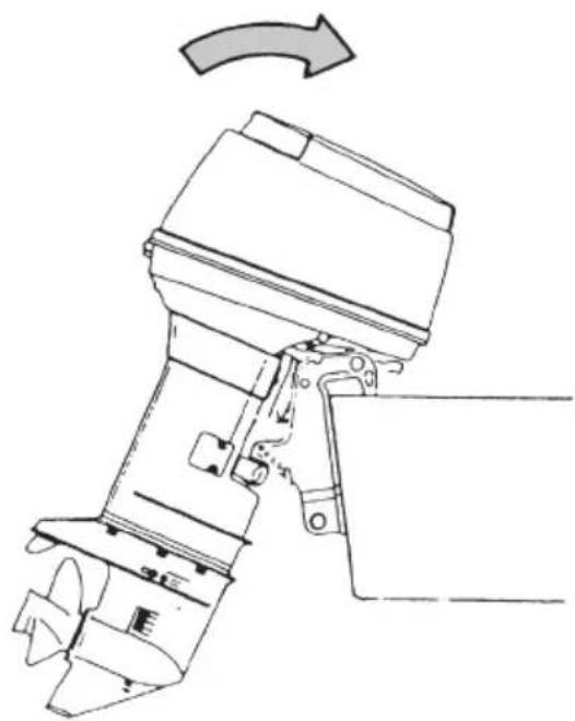
Reverse lock lever2 Tilt the engine up approx.
45^ and lower it. The engine will now be set to the shallow water setting.
natural_image
Technical line drawing of a mechanical device with an arrow indicating rotation (no text or symbols present)3 Releasing the shallow water setting
a. Turn the Reverse Lock Lever upward to set them in "LOCK" position.
b. Tilt up the engine slightly and then let it go down. The shallow water setting is then released.
c. The engine is released from shallow water setting, and locked at normal running position.
5. Stopping the engine

WARNING
- Do not shift into Reverse during planning, or control will be lost leading to serious personal injury, boat may swamp, and/or hull may be damaged.
- Do not shift into Reverse during cruising, or control may be lost, falling down or causing passenger(s) to be thrown overboard. Leading to serious personal injury, and steering system and/or shifting mechanism may be damaged.

CAUTION
Never stop the engine immediately after a full throttle run. Keep it running for two or three minutes at idling speed (Shift Lever set to Neutral) to allow it to cool down.
F type
1 Reduce the engine speed to idling rpm.
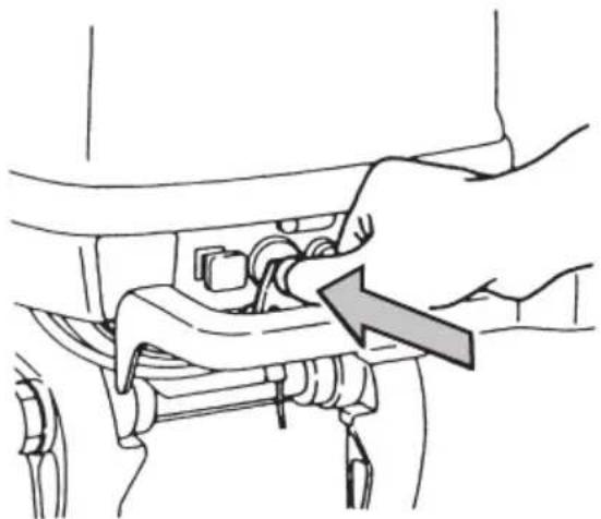
2 Keep pressing on the Stop Switch or pull out the lock plate/ The engine will then stop.
natural_image
Line drawing of a hand adjusting a mechanical component with an arrow indicating direction (no text or symbols)Notes
● After stopping the engine, close the air vent screw on the tank cap.
- Disconnect the fuel connector of the engine or the fuel tank.
- Disconnect the cables from the battery if the engine will not be used for an extended period of time.
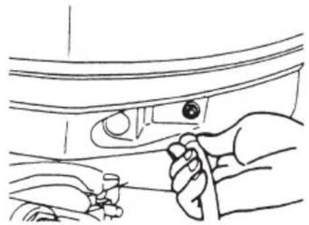
3 Disconnect the fuel connector from the engine.
natural_image
Line drawing of a hand holding a tool near a car intake (no text or symbols)
CAUTION
Never fill up portable fuel tanks on board to avoid fire or explosion resulting from spilled gasoline. If gasoline is ever spilled on board, wipe it up thoroughly. Fuel tanks must always be filled up on land.
4 Close the air vent screw on the fuel tank cap.
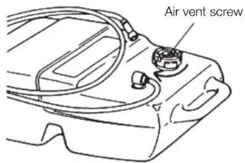
text_image
Air vent screw6. Trim angle
The following instructions explain how to set the best trim angle of the boat.
F type
The trim angle is adjusted by setting the thrust rod in the correct thrust rod hole.
■ Proper trim angle
The trim angle is optimum when the boat is parallel to the water surface while running.
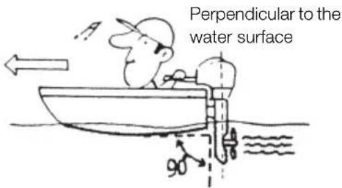
text_image
Perpendicular to the water surface■ Improper trim angle (bow rises too high)
If the trim angle is excessive, the bow will rise out of the water and the speed will decrease.
Furthermore, the bow may sway or the bottom may slam the water while cruising.
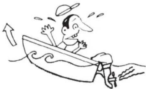
natural_image
Cartoon illustration of a person in a boat with motion lines indicating speed (no text or symbols)In this case, decrease the trim angle by setting the thrust rod in a lower hole.
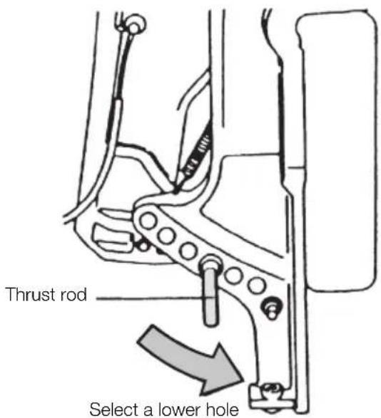
text_image
Thrust rod Select a lower hole■ Improper Trim Angle (bow dips into the water)
If the trim angle is too small, the bow will dip into water, the speed will decrease, and water may enter the boat.
In this case, the trim angle should be increased by setting the thrust rod in a higher hole.
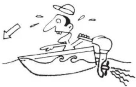
natural_image
Cartoon illustration of a person riding a boat with waves, no text or symbols present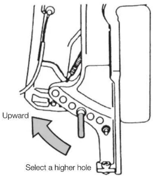
text_image
Upward Select a higher hole
WARNING
- Do not put hand or finger in between outboard motor body and clamp bracket when adjusting trim angle to prevent injury in case the outboard motor body falls.
● Unsuitable trim position can cause loss of control of boat.
When testing a trim position, run boat slow initially to see if it can be controlled safely.

WARNING
Excessive trim up or down may lead to unstable boat operation, potentially causing the steering difficulty that leads to accident during cruising.
- Do not cruise at high speed if improper trim position is suspected. Stop the boat and readjust trim angle before continuing cruise.
- For outboard motor model with PTT switch on the bottom cowl, do not operate the switch during cruising, or control of boat may be lost.
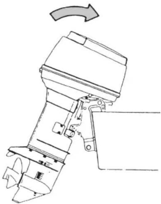
7. Mooring with the engine tilted up
When the engine has been stopped and it will not be used for a long time or when mooring in shallow water, tilt the engine up to prevent damage to the propeller and gear case.
1 Disconnect the fuel connector from the engine.
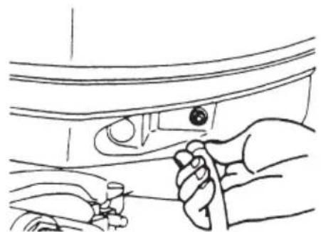
natural_image
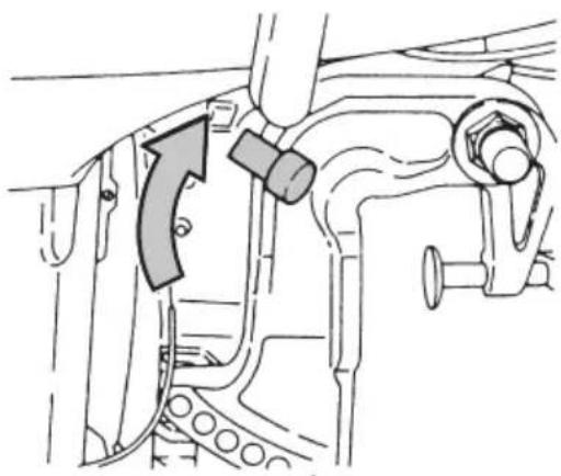
Line drawing of a hand holding a knob inside a car intake hood (no text or symbols)2 Set the Reverse Lock Lever on the starboard side to "RELEASE" by turning it downward.
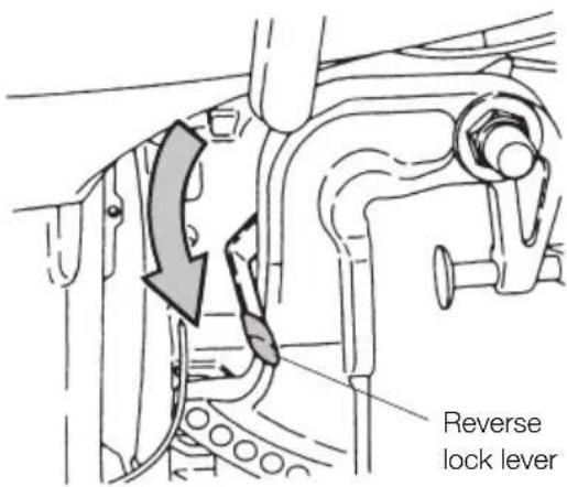
text_image
Reverse lock lever3 Tilt the engine up entirely. The tilt will lock in the raised position.
natural_image
Technical line drawing of a mechanical device with an arrow indicating rotation (no text or symbols present)
WARNING
- Do not put hand or finger in between outboard motor body and clamp bracket when adjusting trim angle to prevent the body parts from being caught in case the outboard motor body falls.
- When tilting up outboard motor with fuel joint for over a few minutes, be sure to disconnect fuel hose or close fuel cock, or fuel may leak, potentially catching fire.

CAUTION
Do not tilt up outboard motor during operation, or engine may be damaged from overheating because of no feed of cooling water.
4 To tilt the engine down, Turn the Reverse Lock Lever upward (toward "LOCK"). Tilt the engine up slightly and then let it go down. (The Reverse Lock will be set automatically.)
natural_image
Mechanical assembly diagram showing a valve mechanism with a directional arrow (no text or labels)REMOVING AND CARRYING THE OUTBOARD MOTOR
1. Removing the outboard motor
1 Stop the engine.
2 Disconnect the fuel connector, the remote control cables, the battery cords, bracket fixing bolts and nuts etc.
3 Remove the outboard motor from the hull and completely drain the water from the gear case.

CAUTION
Do not carry the outboard motor immediately after stopping engine when they are so hot that they burn hands if touched.
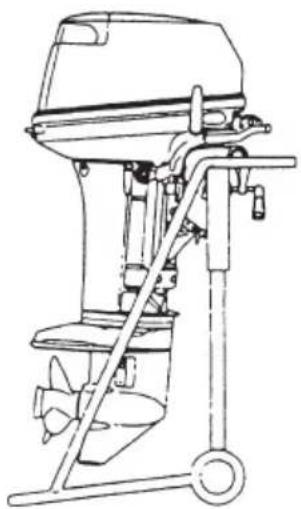
2. Carrying the outboard motor
Be sure to keep the engine vertical whenever you carry the outboard motor.
natural_image
Line drawing of a boat's internal combustion engine (no text or symbols)
WARNING
Close air vent screw of fuel tank and fuel cock before carrying or storing outboard motor and fuel tank, or fuel may leak, potentially catching fire.
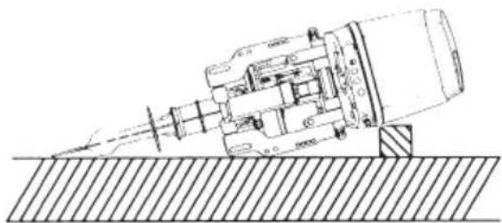
When carrying or putting the engine up for storage, make sure the side with the electric motor of the Power Trim and Tilt is down otherwise air will enter the pump system for the Power Trim and Tilt operation.
natural_image
Technical line drawing of a mechanical device with a pointed tool and base, resting on a hatched surface (no text or symbols)Note
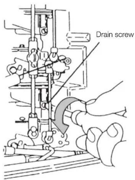
If you can not carry the engine in an upright position, loosen the drain screw on the carburetors to drain fuel from them.
text_image
Drain screw
CAUTION
Beware of explosion danger. Spilled and vapored gasoline may easily catch fire and explode. Be sure to filly discharge gasoline from the carburetors when transporting the engine. Wipe off spilled gasoline with a rag.
3. Storing the outboard motor
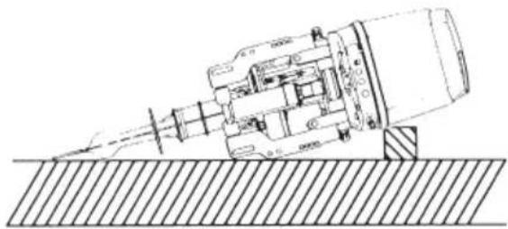
Keep the motor in a vertical position when you store it.
natural_image
Technical line drawing of a mechanical device with motion lines and a hatched base (no text or symbols)Note
If you store the motor in a horizontal position, lay the motor as shown in figure above.

WARNING
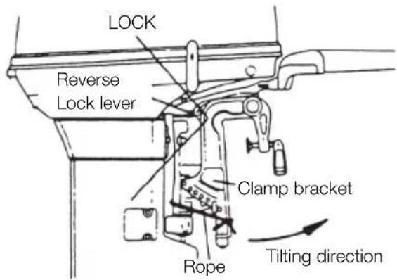
When taking the motor from package or removing the motor from the boat, never release the lock lever. If the lock lever is released, it will be very easy the clamp bracket to spring up to the tilting direction because it is not fixed.
* Tie the clamp bracket to the outboard with a rope.
* Pay attention to the tilting direction so as not to be injured by the springing clamp bracket.
text_image
LOCK Reverse Lock lever Clamp bracket Rope Tilting direction
WARNING
Do not go under outboard motor tilted up even if it is supported by support bar, or accidental fall of outboard motor could lead to severe personal injury.

WARNING
Close air vent screw of fuel tank and fuel cock before carrying or storing outboard motor and fuel tank, or fuel may leak, potentially catching fire.
TRAILERING

CAUTION
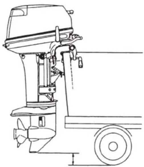
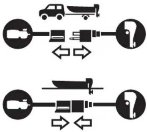
When trailering the outboard motor should be in a vertical (normal running) position, fully down. Trailering in the tilted position may cause damage to the outboard motor, boat, etc.
If trailering with outboard motor fully down is not available (the gear case skeg is too close to the road in a vertical position), fix the outboard motor securely using a device (like a transom saver bar) in the tilted position.
natural_image
Technical line drawing of a right-hand electric motor with propeller and wheels (no text or symbols)
CAUTION
The tilt support device supplied on your outboard motor is not intended for trailering. It is intended to support the outboard motor while the boat is docked, beached, etc.

WARNING
Please disconnect fuel connector except when operating engine.
Fuel leakage is a fire or explosion hazard, which can cause serious injury or death.
flowchart
graph TD
    A["Car"] --> B["Truck"]
    B --> C["Water Pump"]
    C --> D["Truck"]
    D --> E["Truck"]
    E --> F["Truck"]
    F --> G["Truck"]
    G --> H["Truck"]
    H --> I["Truck"]
    I --> J["Truck"]
    J --> K["Truck"]
    K --> L["Truck"]
    L --> M["Truck"]
    M --> N["Truck"]
    N --> O["Truck"]
    O --> P["Truck"]
    P --> Q["Truck"]
    Q --> R["Truck"]
    R --> S["Truck"]
    S --> T["Truck"]
    T --> U["Truck"]
    U --> V["Truck"]
    V --> W["Truck"]
    W --> X["Truck"]
    X --> Y["Truck"]
    Y --> Z["Truck"]
ADJUSTMENT
1. Trim tab adjustment
Adjustment of trim tab angle
After installing outboard motor on the boat, use trim tab to achieve balance between port and starboard steering loads. Loosen trim tab nut, adjust angle of trim tab as described below, and then tighten the nut to specified torque.
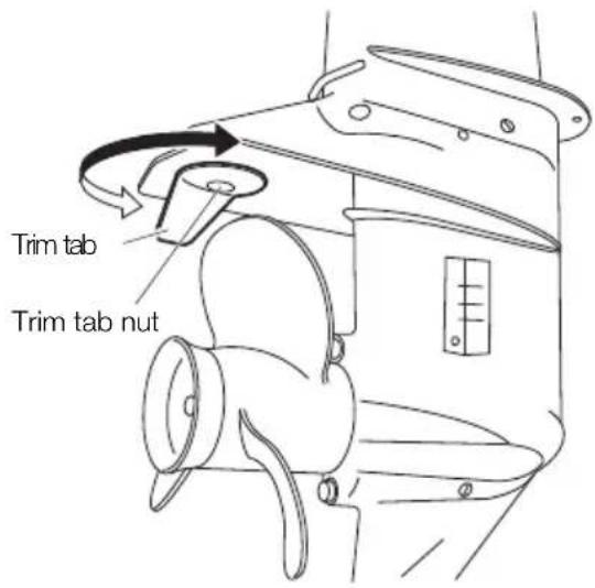
text_image
Trim tab Trim tab nutExample of Adjustment
To keep your outboard motor in the best operating condition, it is very important that you perform daily and periodic maintenance as suggested in the maintenance schedules that follow.
A If it is necessary to steer to port to make boat run straight or if boat steers itself to port when steering is held amidships, move trailing edge of trim tab to port side, or
B If it is necessary to steer to port to make boat run straight or if boat steers itself to starboard when steering is held amidships, move trailing edge of trim tab to starboard side.
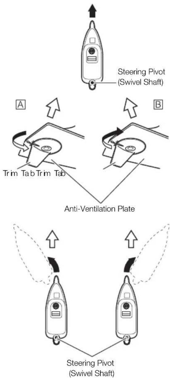
flowchart
graph TD
    A["Steering Pivot (Swivel Shaft)"] --> B["Anti-Ventilation Plate"]
    B --> C["Trim Tab Trim Tab"]
    C --> D["Steering Pivot (Swivel Shaft)"]
    style A fill:#f9f,stroke:#333
    style B fill:#ccf,stroke:#333
    style C fill:#cfc,stroke:#333
    style D fill:#fcc,stroke:#333
Notes
- Change trim tab angle a little for each test run and repeat the process several times until the best position is found.
- The trim tab also acts as an anode to prevent electrolytic corrosion. Therefore do not paint or grease this part.
● After adjustment securely tighten the trim tab fixing bolt. - Check for looseness of the bolt and the trim tab at regular intervals.
Due to corrosion, the trim tab will wear down over time.

WARNING
- Inappropriate adjustment of trim tab could cause steering difficulty. After installing or readjusting trim tab, check if steering load is even.
● Tighten trim tab bolt to specified torque.

WARNING
- Be sure that outboard motor is secured to transom or service stand, or accidental drop or fall of outboard motor could lead to severe personal injury.
- Be sure to lock outboard motor if it is tilted up, or accidental fall of outboard motor could lead to severe personal injury.
- Do not go under outboard motor tilted up and locked, or accidental fall of outboard motor could lead to severe personal injury.
2. Steering load adjustment
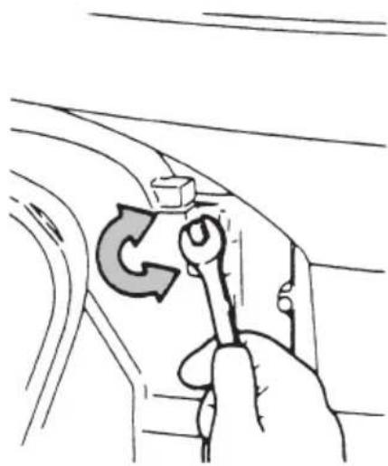
Steering load can be adjusted by turning the steering adjust bolt on the Swivel Bracket.
Turn clockwise to increase load
Turn counter-clockwise to decrease the load
natural_image
Hand holding a wrench inside a car window with a circular arrow symbol (no text or labels)3. Throttle grip turning load adjustment
Turn the friction adjustment screw on the steering handle to adjust the turning load of the throttle grip.
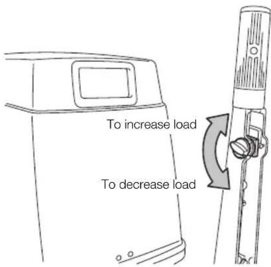
text_image
To increase load To decrease load
WARNING
Do not increase throttle friction excessively, or heavy movement of throttle grip or remote control lever movement could cause loss of throttle control potentially leading to accident.
INSPECTION AND MAINTENANCE
Care of your outboard motor
To keep your outboard motor in the best operating condition, it is very important that you perform daily and periodic maintenance as suggested in the maintenance schedules that follow.

CAUTION
- Your personal safety and that of your passengers depends on how well you maintain your outboard motor. Carefully observe all of the inspection and maintenance procedures described in this section.
- The maintenance intervals shown in the checklist apply to an outboard motor in normal use. If you use your outboard motor under severe conditions such as frequent full-throttle operation, frequent operation in brackish water, or for commercial use, maintenance should be performed at shorter intervals. If in doubt, consult your dealer for advice.
- We strongly recommend that you use only genuine replacement parts on your outboard motor. Damage to your outboard motor arising from the use of other than genuine parts is not covered under the warranty.
1. Daily inspection
Perform the following checks and inspection before and after use.

WARNING
Do not use outboard motor on which any abnormality is found during pre-operation check, or it could go into trouble during cruising potentially leading to accident.
| Item Points to Check Action | ||
| Fuel System | Check the amount of fuel in the tank.Check for dust or water in the fuel filter.Check rubber pipes for oil leakage. | ReplenishCleanReplace |
| Lubrication System | Check the amount of engine oil in the oil tank.Check for dust or water in the oil filters. | ReplenishClean |
| Electrical Equipment | Check the spark plugs for dirt, wear and carbon built-up. Spark plugs: NGK B-8HS-10/NGK BR-8HS-10Check if the main switch functions normally.Check if the battery electrolyte level and specific gravity are normal.Check for loose connections on battery terminal.Check if the emergency stop switch functions normally and make sure the lock plate is present.Check cords for loose connections and damage. | Clean or replaceRemedy or replaceReplenish or rechargeRetightenRemedy or replaceCorrect or replace |
| Throttle System | Check if the choke solenoid and valve for the carburetor works normally.Check if the carburetor and magneto work normally when turning the throttle grip, and also check links for looseness. | ReplaceCorrect |
| Recoil Starter | Check for we and damage.Check the ratchet for engagement. | ReplaceCorrect or replace |
| Clutch and Propeller System | Check the propeler for bent or damaged blades.Check if the propeller nut is tightened ant the split pin is present. | Replace |
| Installation of Motor | Check all the motor installation bolts with the boat.Check the thrust rod installation. | TightenTighten |
| Cooling Water | Check that cooling water is discharged from the cooling water check port after the engine has started. | |
| Tools and Spares | To be ready tools and spare parts for replacing spark plugs, propeller, etc.Check if the spare rope is provided. | |
| Steering Devices | Check working of steering handle and remote control. | |
| Other Parts | Check if the anode and trim tab are securely installed.Check the anode and trim tab for corrosion and deformation. | Repair if necessaryReplace |
Washing with fresh water
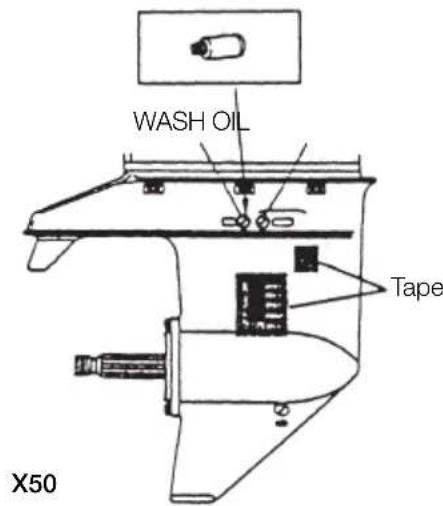
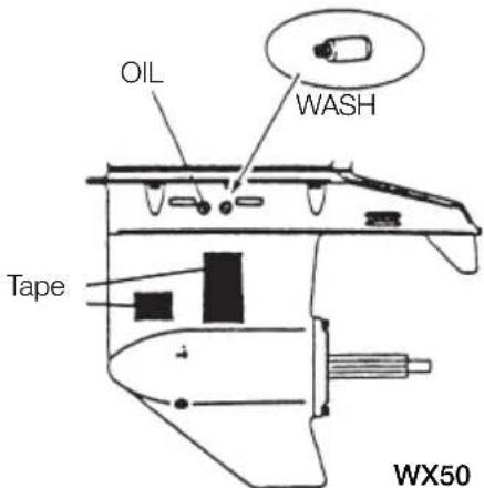
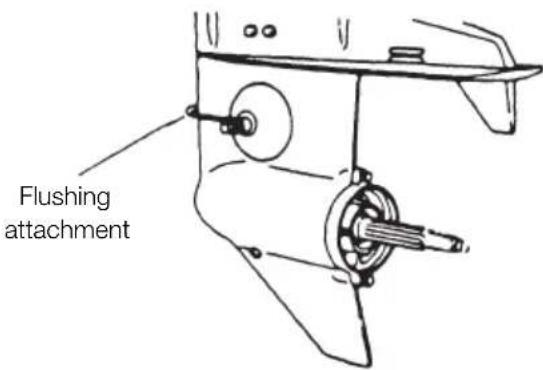
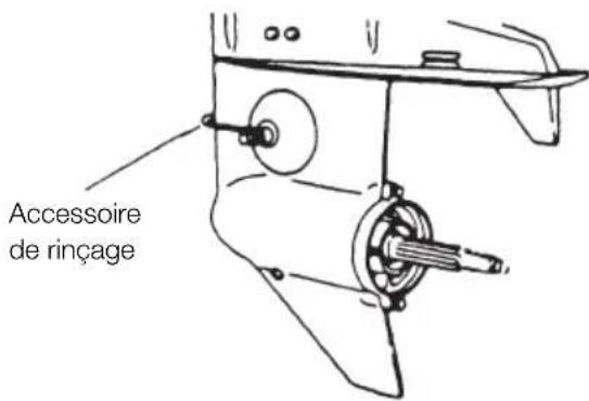
When the engine has been used in salt water or polluted water, wash the exterior and flush the cooling passage with fresh water using the flushing attachment.
Screw the included flushing attachment into the wash hole on the gear case.
Connect a water hose to the flushing attachment and flush out with water.
( Be sure to secure the water inlet and sub-water inlet on the gear case beforehand.)

CAUTION
Keep cooling water passage free of clogs, or lack of cooling water flow could lead to engine overheating, potentially resulting in engine trouble.

WARNING
Do not start engine without removing propeller, or accidentally turning propeller could cause personal injury.

WARNING
Never start or operate the engine indoors or in any space which is not well ventilated. Exhaust gas contains carbon monoxide, a colorless and odorless gas which can be fatal if inhaled for any length of time.
Note
It is recommended to check chemical properties of water on which your outboard motor is regularly used.
Flushing plug (Optional)
text_image
WASH OIL Tape X50Flushing plug (Optional)
text_image
OIL WASH Tape WX50
CAUTION
Keep engine at idle speed during flushing.
Wash the engine before long-term storage. Run the engine at low speed with the Remote Control lever (or Shift lever) set to Neutral to flush out fresh water from the cooling system and in the process remove salt, mud and other foreign particles.
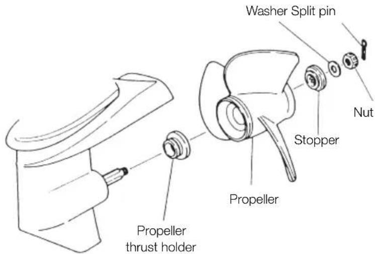
Replacing the propeller
A worn-out or bent propeller will lower the motor's performance, and cause engine trouble.
Before removing the propeller, remove the spark plug caps from the spark plugs to protect against personal injury.

WARNING
Do not begin propeller removal and installation procedure with spark plug caps attached, shift in forward or reverse, main switch at other than "OFF", engine stop cord attached to the switch, and starter key attached, or engine could accidentally start leading to serious personal injury. Disconnect battery cable if possible.
1 Pull out the split pin and remove the propeller nut and washer.
2 Remove the propeller by pulling toward you.
3 Apply genuine grease to the propeller shaft before mounting the new propeller.
4 Fit the washer, securely tighten the nut and insert the split pin.

WARNING
Do not hold propeller with hand(s) when loosening or tightening propeller nut. Put a piece of wood block between propeller blade and anti-ventilation plate to hold propeller.

CAUTION
- Do not install propeller without thrust holder, or propeller boss could be damaged.
- Do not reuse split pin.
● After putting split pin, open the end to prevent it from coming off which could lead to coming off of propeller.
text_image
Washer Split pin Nut Stopper Propeller Propeller thrust holderReplacing the spark plugs

WARNING
- Do not reuse spark plug with damaged insulation, or sparks can leak through crack, potentially leading to electric shock, explosion and/or fire.
- Do not touch spark plugs immediately after stopping engine as they will be hot and could cause severe burns if touched. Allow motor to cool down first.
Note
When inspecting the plug, always clean the gasket surface and use a new gasket. Wipe off any dirt from the threads and screw in the spark plug to the correct torque.
If the spark plug(s) is fouled, has carbon build up, or is worn, it should be replaced. When reusing spark plugs, remove dirt from the electrodes and adjust spark gap to specification.
1 Remove the top cowl.
2 Remove the spark plugs by turning counter-clockwise with the socket wrench (21 mm: 13/16 in) fitted with the handle. Tap lightly on the spark plugs if they are hard to turn.
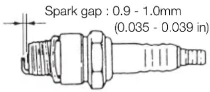
Use spark plug NGK B8HS-10.
text_image
Spark gap : 0.9 - 1.0mm (0.035 - 0.039 in)Notes
- Spark plug torque : 27.0Nm (20ft-lb) (2.7kgf-m)
If a torque-wrench is not available when you are fitting a spark plug, a good estimate of the correct torque is 1/4 to 1/2 a turn past finger-tight. Have the spark plug adjusted to the correct torque as soon as possible with a torque-wrench.

CAUTION
Do not touch the high tension cords running from the ignition coil to the spark plugs while the engine is running or is turned by the electric starter motor, not even for testing the high tension cords or the spark plugs.
The high tension cords and the spark plugs generate very high electric voltage, which can cause a serious electric shock if touched.
2. Periodic inspection
It is important to inspect and maintain your outboard motor regularly. At each interval on the chart below, be sure to perform the indicated servicing. Maintenance intervals should be determined according to the number of hours or number of months, whichever comes first.
For periodic inspection and maintenance, consult your servicing dealer.
| Item | Servicing Interval | Action Remarks | ||||
| 10 hours or 1 month | 50 hours or 3 months | Every 100 hours or 6 months | ||||
| Fuel System | *Carburetor | ● | ● | Strip, clean and adjust. Adjust idling. | ||
| Fuel filter | ● | ● | ● | Check and clean. | ||
| Piping | ● | Check and clean. | ||||
| Fuel tank | ● | ● | ● | Clean | ||
| Ignition | Spark plugs | ● | ● | ● | Check gaps. Remove carbon deposits. | |
| *Ignition timing | ● | ● | Adjust timing. | |||
| Starting System | *Starter motor | ● | Check for salt deposits and battery cable condition. | |||
| Battery | ● | ● | ● | Installation, fluid quantity, gravity | ||
| Starter rope | ● | ● | ● | Check for wear or damage | ||
Note
Your outboard motor should receive careful, and complete inspection at 300 hours. This is the best time for major maintenance procedures to be carried out.
| Item | Servicing Interval | Action Remarks | ||||
| 10 hours or 1 month | 50 hours or 3 months | Every 100 hours or 6 months | ||||
| Lower Unit | Propeller | ● | ● | ● | Bend of blades damage, wear | |
| Gear oil | ● | ● | ● | Change of oil or replenishment and water leak. | ||
| Water pump | ● | ● | Check for wear or damage. | Replace impeller every 12 months. | ||
| Bolt and Nuts | ● | ● | ● | Retighten | ||
| Sliding and Rotating Parts. Grease Nipples | ● | ● | Apply and pump in grease. | |||
| *Engine Oil System | Oil tank | ● | ● | Check for leakage. damage, position of clips, and filter conditions. | Repair or consult your dealer. | |
| Oil pipe | ||||||
| Oil filter | ||||||
| Outer Equipment | ● | ● | ● | Check corrosion | ||
| Anode | ● | ● | Check corrosion and deformation. | Replace | ||
For checking the items marked with *, consult with your dealer.
Inspecting and replacing anodes
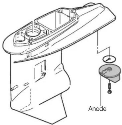
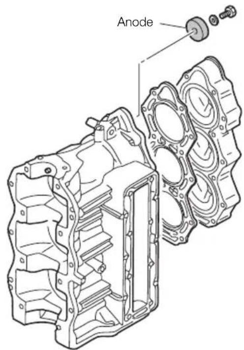
Tohatsu outboard motors are protected from galvanic corrosion by anodes.
Inspect and replace anodes if volume is to 75% of new parts.

CAUTION
Anode protects outboard motor from galvanic corrosion.
Do not paint or apply grease or oil to anode.
Doing so disables the anode.
1 Gear Case
text_image
Anode9
2 Transom bracket

text_image
Anode3 Cylinder
text_image
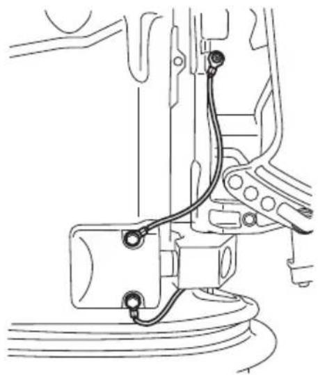
AnodeChecking wiring and connectors
Check each grounding wire is properly secured.
natural_image
Technical line drawing of a mechanical assembly with wires and components (no text or symbols)Replacing gear oil

WARNING
- Be sure that outboard motor is secured to transom or service stand, or accidental drop or fall of outboard motor could lead to severe personal injury.
- Be sure to lock outboard motor if it is tilted up, or accidental fall of outboard motor could lead to severe personal injury.
- Do not go under outboard motor tilted up and locked, or accidental fall of outboard motor could lead to severe personal injury.
1 Remove the oil plugs (upper and lower), and completely drain the gear oil into a pan.
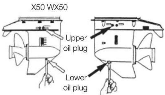
text_image
X50 WX50 Upper oil plug Lower oil plug2 Insert the oil tube nozzle into the lower oil plug hole, and fill with gear oil by squeezing the oil tube until oil flows out of the upper plug hole.
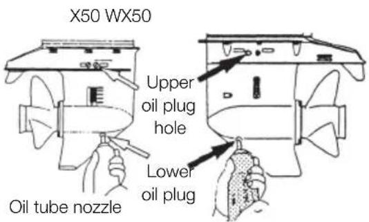
text_image
X50 WX50 Upper oil plug hole Lower oil plug Oil tube nozzle3 Install the upper oil plug, and then remove oil tube nozzle and install the lower oil plug.
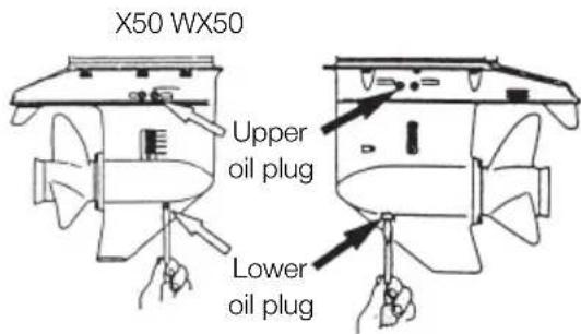
text_image
X50 WX50 Upper oil plug Lower oil plug
CAUTION
Do not reuse oil plug gasket. Always use new gasket and tighten oil plug properly to prevent entry of water into lower unit.
Note
If water in the oil, giving it a milky colored appearance. Contact your dealer.
Note
Use only genuine or recommended gear oil or, if not available, an API (American Petroleum Institute) oil grade of GL5 SAE #80\~SAE#90.
Required volume
: 50 approx. 500mL (16.89 U.S. fluid oz)
: W50 approx. 700mL (23.65 U.S fluid oz)
Cleaning tanks and filters

WARNING
Gasoline and its vapors are very inflammable and can be explosive.
- Do not start this procedure while engine is operating or hot even after stopping it.
- Place fuel filter away from every source of ignition such as sparks or open flames.
- Wipe off gasoline well immediately if spilled.
● Install fuel filter with all related parts in place, or fuel leak could occur, leading to catching fire or explosion. - Check fuel system regularly for leakage.
- Contact Tohatsu dealer for fuel system services. Services by unqualified person could lead to engine damage.
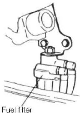
● Fuel filters are provided inside the fuel tank and on the engine.
Loosen a Fuel Pick-up Elbow and remove it. Then clean the Fuel Filter.
- Cleaning Fuel Tank Water or dirt in the fuel tank may cause engine trouble. Clean the tank at specified times or after long time storage (over three months).
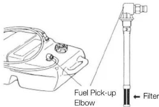
text_image
Fuel Pick-up Elbow Filter- Clean the filters on the engine after removing the fuel filter cases.
text_image
Fuel filter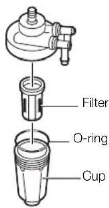
text_image
Filter O-ring Cup3. Off-season storage

WARNING
- When the motor is out of the water, being transported, or in storage, always remove the negative (-) battery cable to prevent accidental starting of the engine. Accidental starting when the motor is out of the water will cause water pump failure, overheating and damage to the engine due to a lack of cooling water.
- DO NOT disconnect the electrical harness when operating the motor. This model will continue to run and can be started with the electrical harness disconnected. Remove all spark plug connectors from the spark plugs when servicing the engine or propeller.
When your outboard motor is in storage, this is a good opportunity to have it serviced or overhauled by your dealer.
■ Engine
1 Wash the engine exterior and flush the cooling water system thoroughly with fresh water. Let the water drain completely.
Wipe off any surface water with an oily rag.
2 Drain all fuel from the fuel pipes, fuel pump and carburetor, and clean these parts. To prevent corrosion of the fuel tank, fill it up with engine oil-rich gasoline.
Keep in mind that if gasoline is kept in the carburetor for a long time, gum and varnish will be generated, causing the float valve to stick.
3 Remove the spark plugs and feed genuine engine oil or storage fogging oil through the spark plug holes.
The oil will be fed into the crank case from the air silencer attached to the carburetors. Turn the engine over several times while feeding the oil into it and make sure it is evenly distributed.
4 Apply grease to the propeller shaft.
5 Change the gear oil in the gear case.
6 Apply grease to all sliding parts, joints, nuts, and bolts.
7 Use a dry cloth to completely wipe off water and salt from the electrical components.
8 Remove the fuel connector from the engine.
9 Stand the outboard motor up vertically in a dry place.

WARNING
Be sure to use cloth to remove fuel remaining in the cowl and dispose of it in accordance with local fire prevention and environment protection regulations.
4. Pre-season check
Have your dealer check the engine before the season starts, or if your prefer, be sure to check the following items yourself:
1 Check that the shift and throttle function properly.
(Be sure to turn the propeller shaft when checking the shift function or else the shift linkage may be damaged.)
CAUTION
The following steps must be taken when first using the engine after pre-season storage.
- Mix engine oil with the fuel in the following mixing ratio and fill up the fuel tank completely with 25 liters (6.6 U.S. gal.): Mixing ratio : Gasoline 25 : 1 Engine oil Use unleaded gasoline and genuine Outboard Motor oil. If this oil is not available, use another NMMA TC-W3 certified outboard motor oil from another manufacture.
● Purge any air from the oil filter assembly. - Warm up the engine for 3 minutes with the remote control lever in "NEUTRAL" position.
- Run the engine for 5 minutes at the slowest speed.
- Run the engine for 10 minutes at the half speed.
In steps 2 and 3 above, the oil used for winter storage inside the engine will be cleaned out, and optimum performance will be assured.
- When the full volume, 25 liters (6.6 U.S. gal.), of gasoline mixed with oil has been used, fill up the tank with pure gasoline only. (For the auto-mixing types)
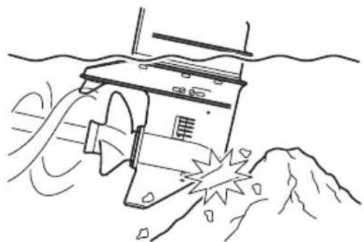
5. Checking after striking underwater object
Striking sea bottom or underwater object may severely damage the outboard motor. Immediately bring the outboard motor to your dealer and ask for the following checks.
1 Looseness or damage of power unit installation bolts, gear case and extension case bolts, propeller or propeller shaft, upper and lower mount rubber bolts and nuts, power trim and tilt bolts, and mount rubber cap bolts.
Ask to tighten loose bolts and nuts, and to replace damaged parts.
2 Deformation and damage of mount rubber, tilt stopper, thrust rod, gears and clutch, and propeller.
Ask to replace damaged or deformed parts.
natural_image
Line drawing of a submarine partially submerged in water with visible exhaust plume (no text or symbols)6. If the engine becomes submerged in water
After pick up, immediately bring the out-board to your dealer.
Following are the emergency measures to be taken on the submerged outboard.
1 Take it out of water immediately and wash it with fresh water to remove all traces of salt and dirt.
2 Remove the spark plugs, and drain the engine completely of water.
Turn the flywheel several times, using the starter rope.
3 Inject a liberal amount of genuine engine oil or storage fogging oil into the engine through the spark plug holes and the air silencer.
Turn the flywheel several times with the starter rope while injecting the oil to make sure the oil is evenly distributed.
4 After the above steps, it is still possible for the internal engine parts to be damaged. The electrical components and carburetors will soon deteriorate and become inoperative. Therefore, be sure to have the engine completely overhauled by a service shop immediately.
CAUTION
Do not attempt to start submerged outboard motor immediately after it is recovered, or engine could be severely damaged.
7. Precautions in cold weather
When morning in cold weather at sub-zero temperatures the water in the cooling water pump may freeze and severely damage the pump, impeller, and associated parts. To avoid this, submerge the lower half of the engine into the water, or tilt the engine up above water level and the recoil starter several times to drain the water completely.
TROUBLESHOOTING
If you encounter problem with the engine, check the list below and locate the problem you are experiencing. Then follow the suggested remedies.
Do not hesitate to contact your dealer, as professionals advice and assistance is the best way to keep the engine in optimum condition.
| Difficult to start engine | Engine starts, but stops soon | Poor idling | Unstable engine running speed or engine stops | Abnormally high engine speed | Abnormally low engine speeds | Cannot obtain high engine speeds | Overheat-ing of engine | |
| ● | ● | ● | Empty fuel tank | |||||
| ● | ● | ● | ● | ● | ● | ● | Incorrect connection of fuel system | |
| ● | ● | ● | ● | ● | ● | ● | Air enters fuel line | |
| ● | ● | ● | ● | ● | ● | ● | Deformed or damaged fuel pipe | |
| ● | ● | ● | ● | ● | ● | ● | Closed air vent on fuel tank cap | |
| ● | ● | ● | ● | ● | ● | ● | Clogged fuel filter, fuel pump or carburetor | |
| ● | ● | ● | ● | ● | Use of improper engine oil | |||
| ● | ● | ● | ● | ● | ● | Use of improper gasoline | ||
| ● | ● | Excessive supply of gasoline | ||||||
| ● | ● | ● | ● | ● | ● | ● | Poor carburetor adjustment | |
| ● | ● | ● | ● | ● | ● | Recirculation pipe broken | ||
| ● | ● | ● | ● | ● | ● | ● | Use of non-specified spark plugs | |
| ● | ● | ● | ● | ● | ● | Dirt or carbon deposits on spark plugs | ||
| ● | ● | ● | ● | ● | ● | No sparks or weak sparks | ||
| ● | ● | ● | ● | Insufficient cooling water flow | ||||
| ● | ● | ● | ● | Faulty thermostat | ||||
| ● | ● | ● | Propeller cavitation | |||||
| ● | ● | ● | ● | Incorrect propeller selection | ||||
| ● | ● | ● | ● | ● | Damaged or bent propeller | |||
| ● | ● | ● | ● | Unbalanced load in boat | ||||
| ● | ● | ● | Transom too high | |||||
| ● | ● | ● | Transom too low | |||||
| ● | ● | ● | ● | ● | ● | Incorrect adjustment of throttle link | ||
| ● | ● | ● | ● | ● | ● | Incorrect adjustment of ignition timing | ||
| ● | Insufficient battery capacity, loose terminals, corrosion | |||||||
| ● | Safety switch lock plate not fitted |
■ TOOL KIT AND SPARE PARTS
The following a list of the tools and spare parts provided with the motor.
| Name Quantity Remark | |||
| Servicing Tools | Tool Bag | 1 | |
| Socket Wrench (21mm) | 1 | ||
| Socket Wrench (10 x 13) | 1 | ||
| Socket Wrench Handle | 1 | ||
| Pliers | 1 | ||
| Screwdriver (Phillips-type and flat head) | 1 | A d a p | |
| Spare Parts | Cylinder Head Cover Gasket | 1 | |
| Cylinder Head Gasket | 1 | ||
| Engine Basement Gasket | 1 | ||
| Float Valve | 3 | ||
| Throttle Wire | 2 | ||
| Anode (for Bracket) | 1 | ||
| Trim Tab | 1 | ||
| Water Pump Impeller | 1 | ||
| Guide Plate Gasket | 1 | ||
| Pump Case Gasket | 1 | ||
| Gasket (for Gear Oil Plug) | 2 | ||
| Grease | 1 | ||
| Starter Rope | 1 | ||
| Spark Plug | 3 | NGK B8HS-10 | |
| Split Pin | 1 | ||
| Rigging Bolt Set [Bolt] | 4 | 12mm | |
| 4 | 12mm | ||
| 4 | |||
| Parts Packaged with Engine* | Fuel Tank (with primer bulb) | 1 | |
| Grease Up Point Chart | 1 | ||
| Owner's Manual | 1 | ||
| Caution Label Information Card | 1 | ||
* Not included as standard accessories in some markets.
OPTIONAL ACCESSORIES
natural_image
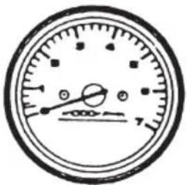
Simple line drawing of a circular gauge or dial with no text or symbolsTachometer
natural_image
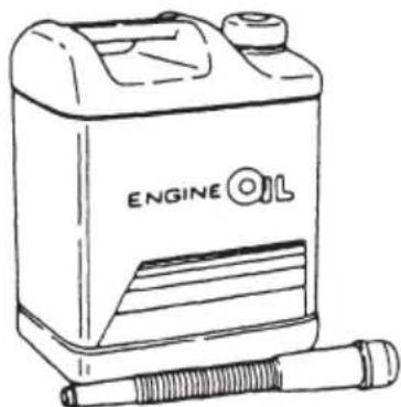
Line drawing of an engine oil can with a cylindrical sensor attached (no text or symbols)Engine oil (0.4L, 1L, 4L, 20L)

Flushing plug
natural_image
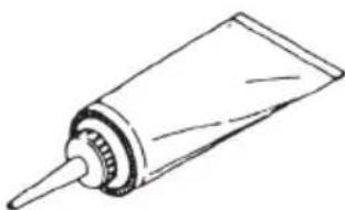
Simple line drawing of a cylindrical object with a pointed tip, resembling a tool or tube (no text or symbols)Genuine gear oil (500ml)
text_image
Flushing attachment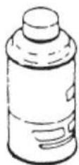
Touch-up Spray Paint
natural_image
Simple line drawing of a mechanical component with no text or symbolsPropeller
■ PROPELLER TABLE
To ensure optimum performance, the propeller should match the boat type and its load.
Use a genuine propeller.
A propeller must be selected so that the engine rpm measured at wide open throttle, while cruising, is within the recommended range.
50D2 5,150 to 5,850 rpm
50
| Mark | Propeller Size (Diameter Pitch) | ||
| Inch mm | |||
| Heavier Load | 7* 11.4 x 7.1 290 x 180 | ||
| 9 12.1 x 9.0 307 x 229 | |||
| 11 11.6 x 11.0 295 x 279 | |||
| 12 11.4 x 12.0 290 x 305 | |||
| 13 11.1 x 13.0 282 x 330 | |||
| 14 11.1 x 14.0 282 x 356 | |||
| Lighter Load | 15 11.0 x 15.0 279 x 381 | ||
* shows propeller with four blades.
W50
| Mark | Propeller Size (Diameter Pitch) | |||
| Inch mm | ||||
| Heavier Load | 9 12 x 9.0 305 | x 229 | ||
| 10 11.5 x 10.0 | 292 x 254 | |||
| 11 11.5 x 11.0 | 292 x 279 | |||
| 12 11.6 x 12.0 | 295 x 305 | |||
| 13 11.5 x 13.0 | 292 x 330 | |||
| 14 11.4 x 14.0 | 289 x 355 | |||
| 15 11.0 x 15.0 | 280 x 381 | |||
| 16.5 10.7 x 16.4 | 273 x 417 | |||
| Lighter Load | 17.5 10.9 x 17.6 | 276 x 447 | ||
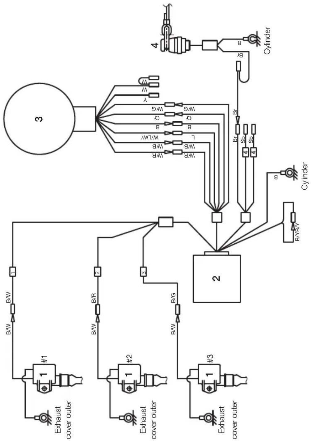
WIRING DIAGRAM
MX50D2
-
Ignition coil
-
C.D. unit
-
Magneto
-
Stop switch
| Cord colors | |
| B | Black |
| Or | Orange |
| Y | Yellow |
| W | White |
| Br | Brown |
| Sb | Sky blue |
| B/W | Black/White |
| B/G | Black/Green |
| B/Y | Black/Yellow |
| W/R | White/Red |
| W/B | White/Black |
| W/G | White/Green |
| L/W | Blue/White |
* Slashes (/) indicate striped
cord colors
flowchart
graph TD
    A["Exhaust cover outer"] --> B["1 #1"]
    B --> C["B/W"]
    C --> D["B/W"]
    D --> E["1"]
    F["Exhaust cover outer"] --> G["1 #2"]
    G --> H["B/W"]
    H --> I["B/R"]
    I --> J["2"]
    K["Exhaust cover outer"] --> L["1 #3"]
    L --> M["B/W"]
    M --> N["B/G"]
    N --> O["3"]
    P["Cylinder"] --> Q["4"]
    Q --> R["Br"]
    R --> S["Sb"]
    R --> T["Sb"]
    U["3"] --> V["W/R"]
    V --> W["W/B"]
    V --> X["W/LW/"]
    V --> Y["B"]
    V --> Z["Or"]
    V --> AA["W/G"]
    V --> AB["Y"]
    V --> AC["W"]
    V --> AD["W"]
    V --> AE["Br"]
    V --> AF["Br/YB/Y"]
    V --> AG["Cylinder"]
OWNER'S MANUAL
EverRun
MX 50D₂
MWX 50D₂
MANUEL DE L'UTILISATEUR
natural_image
Technical line drawing of a right-hand electric motor (no text or symbols)EverRun
MX 50D₂
MWX 50D₂
OB No.003-11098-0
⚠️ VEUILLEZ LIRE ATTENTIVEMENT CE MANUEL AVANT D'UTILISER LE MOTEUR HORS-BORD. LE NON-RESPECT DES INSTRUCTIONS ET DES MESURES DE SECURITE CONTENUES DANS CE MANUEL PEUT ENTRAINER DES PREJUDICES CORPORELS GRAVES OU UN ACCIDENT MORTEL. CONSERVEZ CE MANUEL DANS UN LIEU SUR POUR TOUTE REFERENCE ULTERIEURE.
text_image
TOHATSU CORPORATION Made in Japan SERIAL No. RATED POWER FULL THROTTLE RANGE r/min MASS kgCher client
text_image
Technical diagram of an electric motor with numbered parts for identification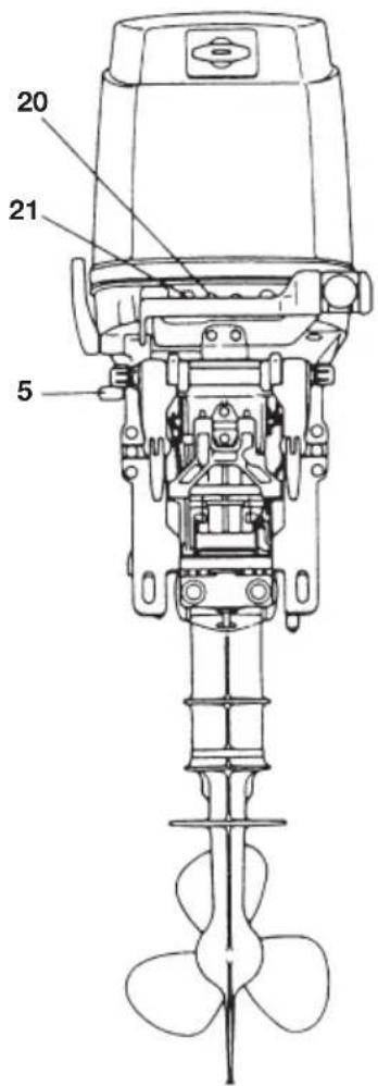
text_image
20 21 5text_image
10 ~ 30 mm (0.4 ~ 1.2 in) Plaque anti-cavitationline
| X-axis Label | Y-axis Value | | ------------ | ------------ | | 0 | 0 | | 10L | 0.4 | | 10L | 0.2 | | 10L | 0.5 | | 10L | 1.0 |Essence
flowchart
graph TD
    A["Eye Care"] --> B["Injection Pump"]
    B --> C["Anatomical Procedure"]
    C --> D["Patient Injection"]
natural_image
Line drawing of a hand operating a mechanical component with a central shaft (no text or symbols)natural_image
Hand holding a tool with a knob and arrow indicating direction (no text or symbols)natural_image
Technical line drawing of a car interior showing a bracket and gear mechanism with directional arrows (no text or symbols)Note
natural_image
Hand holding a screwdriver inserted into a mechanical component, with no visible text or symbolsnatural_image
Line drawing of a hand using a tool to lift a mechanical component (no text or symbols)
AVERTISSEMENT
natural_image
Technical diagram of a mechanical assembly with no visible text or symbolsnatural_image
Technical line drawing of a mechanical device with an arrow indicating rotation (no text or symbols present)natural_image
Line drawing of a hand operating a car's steering wheel (no text or symbols)Notes
natural_image
Line drawing of a hand holding a tool near a car's side panel (no text or symbols)CONSEIL DE PRUDENCE
natural_image
Cartoon illustration of a person in a boat with an upward arrow, no text or symbols presentnatural_image
Cartoon illustration of a man riding a boat with a hat and surfboard, no text or symbols present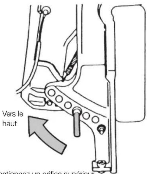
natural_image
Line drawing of a hand holding a tool near a car's side panel (no text or symbols)natural_image
Line drawing of a mechanical device with an arrow indicating rotational motion (no text or symbols)! AVERTISSEMENT
natural_image
Mechanical assembly diagram showing a valve mechanism with no visible text or symbolsDÉPOSE ET TRANSPORT DU MOTEUR HORS-BORD
natural_image
Line drawing of a small boat or motor with handle and spoked base (no text or symbols)
AVERTISSEMENT
natural_image
Technical line drawing of a mechanical device with a pointed tool and base, resting on a hatched surface (no text or symbols)Note
natural_image
Technical line drawing of a mechanical device with a pointed tool and base, resting on a hatched surface (no text or symbols)Note
natural_image
Technical line drawing of a right-hand electric motor with propeller and wheels (no text or symbols)CONSEIL DE PRUDENCE
natural_image
Hand holding a wrench inside a car window with a circular arrow symbol (no text or labels)natural_image
Line drawing of a spark plug with threaded end and hexagonal base (no text or symbols)Notes
natural_image
Technical line drawing of a mechanical assembly with no visible text or symbolsnatural_image
Line drawing of a ship navigating through water with visible wake and hull (no text or symbols)6. Moteur immergé
natural_image
Simple line drawing of a circular gauge or dial with no text or symbolsCompte-tours

Bouchon de rinçage
text_image
Accessoire de rinçage
natural_image
Simple line drawing of a mechanical component with no text or symbolsHélice
natural_image
Line drawing of an engine oil can with a cylindrical connector (no text or symbols)natural_image
Simple line drawing of a cylindrical object with a pointed tip, resembling a tool or container (no text or symbols)natural_image
Technical line drawing of a right-hand electric motor (no text or symbols)EverRun
MX 50D₂
MWX 50D₂
OB No.003-11098-0
text_image
TOHATSU CORPORATION Made in Japan SERIAL No. RATED POWER FULL THROTTLE RANGE r/min MASS kgtext_image
Technical diagram of an electric motor with numbered parts for identification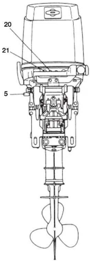
text_image
20 21 5natural_image
Line drawing of a hand operating a mechanical component with a central shaft (no text or symbols)2 Conecte el conector de combustible al motor.
natural_image
Hand holding a tool with a knob and arrow indicating direction (no text or symbols)natural_image
Line drawing of a hand gripping a mechanical component (no text or symbols)natural_image
Technical line drawing of a mechanical component with directional arrows indicating movement (no text or symbols)Nota
natural_image
Line drawing of a hand inserting a plug into a device with an arrow indicating direction (no text or symbols)natural_image
Line drawing of a hand using a tool to lift a mechanical component (no text or symbols)
ADVERTENCIA
text_image
Marcha atrás (R) Adelante (F)
ADVERTENCIA
natural_image
Mechanical assembly diagram showing a valve mechanism with no visible text or symbolsnatural_image
Technical line drawing of a mechanical device with an arrow indicating rotation (no text or symbols present)natural_image
Diagram of a hand operating a vehicle's steering wheel, showing the lever and handle (no text or symbols present)Notas
natural_image
Line drawing of hands operating a car interior with a handle and valve (no text or symbols)
PRECAUCIÓN
natural_image
Cartoon illustration of a person in a boat with an upward arrow and splashing water (no text or symbols)natural_image
Cartoon drawing of a man in a boat with a hat and arrow, no text or symbols present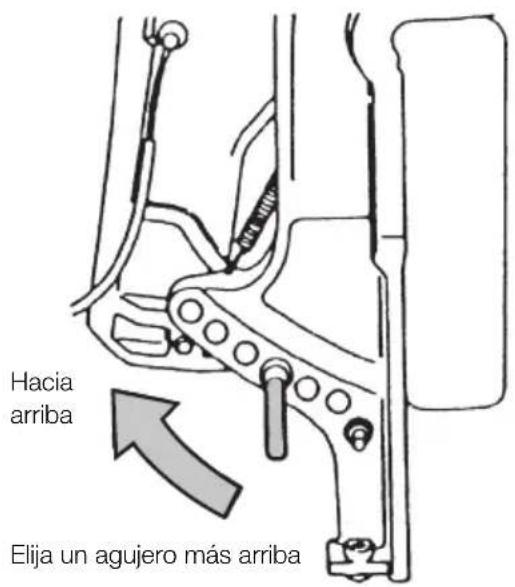
natural_image
Line drawing of a hand holding a tool near a car's side panel (no text or symbols)natural_image
Technical line drawing of a mechanical device with an arrow indicating rotation (no text or symbols present)
ADVERTENCIA
natural_image
Mechanical assembly diagram showing a valve mechanism with no visible text or symbols■ RETIRAR Y TRANSPORTAR EL MOTOR FUERA-BORDA
natural_image
Line drawing of a small boat or motor with handle and spoked base (no text or symbols)
ADVERTENCIA
natural_image
Technical line drawing of a mechanical device with no visible text or symbolsNota
natural_image
Technical line drawing of a mechanical device with a pointed tip and base, resting on a hatched surface (no text or symbols)Nota
natural_image
Technical line drawing of a multi-blade electric motor or engine with propeller and rotor (no text or symbols)PRECAUCIÓN
natural_image
Hand holding a wrench inside a car window with a circular arrow symbol (no text or labels)text_image
0.9 - 1.0 mm (0.035 - 0.039 inNotas
- Par de apriete de las bujías: 27.0 Nm (20 ft-lb) (2.7 kgf-m)
natural_image
Technical line drawing of a mechanical assembly with no visible text or symbolsnatural_image
Technical line drawing of a mechanical component with no visible text or symbolsnatural_image
Line drawing of a submarine partially submerged in water with visible cracks and waves (no text or symbols)natural_image
Simple circular gauge or dial with needle pointing to the center (no text or symbols)Tacómetro

natural_image
Line drawing of an engine oil can with a coiled hose beside it (no text or symbols)Aceite para motor (0.4 L, 1 L, 4 L, 20 L)

Tapón de descarga
natural_image
Simple line drawing of a cylindrical object with a pointed tip, resembling a tool or tube (no text or symbols)natural_image
Simple line drawing of a mechanical component with no text or symbolsHélice
TABLA DE HÉLICES
Address : 5-4, 3-chome, Azusawa, Itabashi-ku,