B85MDGS - Carte mère ASROCK - Free user manual and instructions
Find the device manual for free B85MDGS ASROCK in PDF.
Download the instructions for your Carte mère in PDF format for free! Find your manual B85MDGS - ASROCK and take your electronic device back in hand. On this page are published all the documents necessary for the use of your device. B85MDGS by ASROCK.
USER MANUAL B85MDGS ASROCK
Copyright©2014 ASRock INC. All rights reserved.
No part of this documentation may be reproduced, transcribed, transmitted, or
translated in any language, in any form or by any means, except duplication of
documentation by the purchaser for backup purpose, without written consent of
Products and corporate names appearing in this documentation may or may not
be registered trademarks or copyrights of their respective companies, and are used
only for identication or explanation and to the owners’ benet, without intent to
Specications and information contained in this documentation are furnished for
informational use only and subject to change without notice, and should not be
constructed as a commitment by ASRock. ASRock assumes no responsibility for
any errors or omissions that may appear in this documentation.
With respect to the contents of this documentation, ASRock does not provide
warranty of any kind, either expressed or implied, including but not limited to
the implied warranties or conditions of merchantability or tness for a particular
In no event shall ASRock, its directors, ocers, employees, or agents be liable for
any indirect, special, incidental, or consequential damages (including damages for
loss of prots, loss of business, loss of data, interruption of business and the like),
even if ASRock has been advised of the possibility of such damages arising from any
defect or error in the documentation or product.
is device complies with Part 15 of the FCC Rules. Operation is subject to the following
(1) this device may not cause harmful interference, and
(2) this device must accept any interference received, including interference that
may cause undesired operation.
CALIFORNIA, USA ONLY
e Lithium battery adopted on this motherboard contains Perchlorate, a toxic substance
controlled in Perchlorate Best Management Practices (BMP) regulations passed by the
California Legislature. When you discard the Lithium battery in California, USA, please
follow the related regulations in advance.
“Perchlorate Material-special handling may apply, see www.dtsc.ca.gov/hazardouswaste/
11 Clear CMOS Jumper (CLRCMOS1)
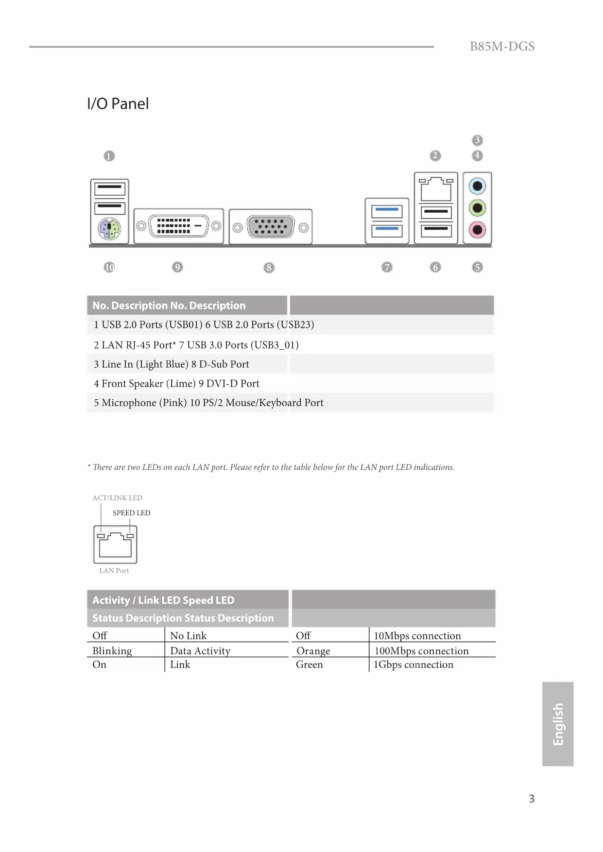
No. Description No. Description
2 LAN RJ-45 Port* 7 USB 3.0 Ports (USB3_01)
3 Line In (Light Blue) 8 D-Sub Port
4 Front Speaker (Lime) 9 DVI-D Port
5 Microphone (Pink) 10 PS/2 Mouse/Keyboard Port * ere are two LEDs on each LAN port. Please refer to the table below for the LAN port LED indications.
Activity / Link LED Speed LED Status Description Status Description
ank you for purchasing ASRock B85M-DGS motherboard, a reliable motherboard
produced under ASRock’s consistently stringent quality control. It delivers excellent
performance with robust design conforming to ASRock’s commitment to quality
1.1 Package Contents
ASRock B85M-DGS Motherboard (Micro ATX Form Factor)
ASRock B85M-DGS Quick Installation Guide
ASRock B85M-DGS Support CD
2 x Serial ATA (SATA) Data Cables (Optional)
1 x I/O Panel Shield Because the motherboard specications and the BIOS soware might be updated, the content of this documentation will be subject to change without notice. In case any modications of this documentation occur, the updated version will be available on ASRock’s website without further notice. If you require technical support related to this motherboard, please visit our website for specic information about the model you are using. You may nd the latest VGA cards and CPU support list on ASRock’s website as well. ASRock website http://www.asrock.com.B85M-DGS
High Density Glass Fabric PCB CPU
Supports Intel® Turbo Boost 2.0 Technology
Dual Channel DDR3 Memory Technology
Supports DDR3 1600/1333/1066 non-ECC, un-buered
Max. capacity of system memory: 16GB (see CAUTION)
be supported only with processors which are GPU integrated.
Supports Intel® HD Graphics Built-in Visuals : Intel® Quick
Sync Video with AVC, MVC (S3D) and MPEG-2 Full
Dual graphics output: support DVI-D and D-Sub by
independent display controllers
Supports DVI-D with max. resolution up to 1920x1200 @
Supports D-Sub with max. resolution up to 1920x1200 @
Supports HDCP with DVI-D Port
Supports Full HD 1080p Blu-ray (BD) playback with DVI-D Port6
Supports Surge Protection (ASRock Full Spike Protection)
Supports Wake-On-WAN
Supports Wake-On-LAN
Supports Lightning/ESD Protection (ASRock Full Spike
Supports LAN Cable Detection
Supports Energy Ecient Ethernet 802.3az
Supports PXE Rear Panel
4 x USB 2.0 Ports (Supports ESD Protection (ASRock Full
2 x USB 3.0 Ports (Supports ESD Protection (ASRock Full
1 x RJ-45 LAN Port with LED (ACT/LINK LED and SPEED LED)
HD Audio Jacks: Line in / Front Speaker / Microphone
4 x SATA3 6.0 Gb/s Connectors, support NCQ, AHCI and
1 x CPU Fan Connector (4-pin)
1 x Chassis Fan Connector (4-pin)
1 x Power Fan Connector (3-pin)
2 x USB 2.0 Headers (Support 4 USB 2.0 ports) (Supports ESD Protection (ASRock Full Spike Protection))
1 x USB 3.0 Header (Supports 2 USB 3.0 ports) (Supports ESD Protection (ASRock Full Spike Protection))
32Mb AMI UEFI Legal BIOS with multilingual GUI support
ACPI 1.1 Compliant wake up events
CPU/Chassis temperature sensing
CPU/Chassis/Power Fan Tachometer
CPU/Chassis Quiet Fan (Auto adjust chassis fan speed by
CPU/Chassis Fan multi-speed control
bit / 7 32-bit / 7 64-bit
ErP/EuP ready (ErP/EuP ready power supply is required)
Please realize that there is a certain risk involved with overclocking, including adjust-
ing the setting in the BIOS, applying Untied Overclocking Technology, or using third-
party overclocking tools. Overclocking may aect your system’s stability, or even cause
damage to the components and devices of your system. It should be done at your own
risk and expense. We are not responsible for possible damage caused by overclocking.
* For detailed product information, please visit our website:
http://www.asrock.com
Due to limitation, the actual memory size may be less than 4GB for the reservation
for system usage under Windows® 32-bit operating systems. Windows® 64-bit operat-
ing systems do not have such limitations. You can use ASRock XFast RAM to utilize
the memory that Windows® cannot use.8
e illustration shows how jumpers are setup. When the jumper cap is placed on
the pins, the jumper is “Short”. If no jumper cap is placed on the pins, the jumper
is “Open”. e illustration shows a 3-pin jumper whose pin1 and pin2 are “Short”
when a jumper cap is placed on these 2 pins.
CLRCMOS1 allows you to clear the data in CMOS. To clear and reset the system
parameters to default setup, please turn o the computer and unplug the power
cord from the power supply. Aer waiting for 15 seconds, use a jumper cap to
short pin2 and pin3 on CLRCMOS1 for 5 seconds. However, please do not clear
the CMOS right aer you update the BIOS. If you need to clear the CMOS when
you just nish updating the BIOS, you must boot up the system rst, and then shut
it down before you do the clear-CMOS action. Please be noted that the password,
date, time, and user default prole will be cleared only if the CMOS battery is
If you clear the CMOS, the case open may be detected. Please adjust the BIOS option
“Clear Status” to clear the record of previous chassis intrusion status.B85M-DGS
1.4 Onboard Headers and Connectors
switch, reset switch and
system status indicator on
the chassis to this header
according to the pin
assignments below. Note
the positive and negative
pins before connecting
GND RESET#PWRBTN#PLED-PLED+ GND HDLED-HDLED+ 1
GND PWRBTN (Power Switch):
Connect to the power switch on the chassis front panel. You may congure the way to
turn o your system using the power switch.
RESET (Reset Switch):
Connect to the reset switch on the chassis front panel. Press the reset switch to restart
the computer if the computer freezes and fails to perform a normal restart.
PLED (System Power LED):
Connect to the power status indicator on the chassis front panel. e LED is on when
the system is operating. e LED keeps blinking when the system is in S1/S3 sleep state.
e LED is o when the system is in S4 sleep state or powered o (S5).
HDLED (Hard Drive Activity LED):
Connect to the hard drive activity LED on the chassis front panel. e LED is on when
the hard drive is reading or writing data.
e front panel design may dier by chassis. A front panel module mainly consists
of power switch, reset switch, power LED, hard drive activity LED, speaker and etc.
When connecting your chassis front panel module to this header, make sure the wire
assignments and the pin assignments are matched correctly.
Onboard headers and connectors are NOT jumpers. Do NOT place jumper caps over
these headers and connectors. Placing jumper caps over the headers and connectors
will cause permanent damage to the motherboard.10
connectors support SATA
data cables for internal
storage devices with up to
6.0 Gb/s data transfer rate.
Besides four USB 2.0 ports
on the I/O panel, there
are two headers on this
motherboard. Each USB
2.0 header can support
Besides two USB 3.0 ports
on the I/O panel, there
is one header on this
motherboard. Each USB
3.0 header can support
connecting audio devices
to the front audio panel.
Please connect the chassis
speaker to this header.
Chassis and Power Fan
Please connect fan cables
to the fan connectors and
match the black wire to
vides a 4-Pin CPU fan
(Quiet Fan) connector.
If you plan to connect a
3-Pin CPU fan, please
connect it to Pin 1-3.
vides a 24-pin ATX power
connector. To use a 20-pin
ATX power supply, please
plug it along Pin 1 and Pin
1. High Denition Audio supports Jack Sensing, but the panel wire on the chassis must
support HDA to function correctly. Please follow the instructions in our manual and
chassis manual to install your system.
2. If you use an AC’97 audio panel, please install it to the front panel audio header by
A. Connect Mic_IN (MIC) to MIC2_L.
B. Connect Audio_R (RIN) to OUT2_R and Audio_L (LIN) to OUT2_L.
C. Connect Ground (GND) to Ground (GND).
D. MIC_RET and OUT_RET are for the HD audio panel only. You don’t need to
connect them for the AC’97 audio panel.
E. To activate the front mic, go to the “FrontMic” Tab in the Realtek Control panel
and adjust “Recording Volume”.
Please connect an ATX
12V power supply to this
supports a serial port
detection feature that
detects if the chassis cove
has been removed. is
feature requires a chassis
with chassis intrusion
is connector supports
Trusted Platform Module
(TPM) system, which can
securely store keys, digital
certicates, passwords,
and data. A TPM system
network security, protects
digital identities, and
ensures platform integrity. CCTS#1RRTS#1DDSR#1DDTR#1RRXD1 GND TTXD1DDCD#1 1 RRI#1 1
connection of printer
Visuals : Intel® Quick Sync Video with AVC, MVC (S3D) and
bit / 7 32-bit / 7 64-bit
•Supporto WOW (Wake-On-WAN)
•Supporta Wake-On-LAN
•Supporto la protezione da fulmini/scariche elettrostatiche
(ESD) (protezione completa ASRock dai picchi di corrente)
•Supporta Energy Ecient Ethernet 802.3az
bit / 7 32-bit / 7 64-bit
bit / 7 32-bit / 7 64-bit
bit / 7 32-bit / 7 64-bit
•Siap untuk ErP/EuP (memerlukan catu daya untuk ErP/EuP)Contact Information
If you need to contact ASRock or want to know more about ASRock, you’re welcome
to visit ASRock’s website at http://www.asrock.com; or you may contact your dealer
for further information. For technical questions, please submit a support request
form at http://www.asrock.com/support/tsd.asp
ASRock Incorporation
2F., No.37, Sec. 2, Jhongyang S. Rd., Beitou District,