
VSX821K - AV receiver PIONEER - Free user manual and instructions
Find the device manual for free VSX821K PIONEER in PDF.
| Product Type | Audio-Video Receiver |
| Brand | Pioneer |
| Model | VSX-821K |
| Output Power | 80 W per channel (8 Ω, 20 Hz - 20 kHz, 0.08 % THD) / 110 W per channel (1 kHz, 8 Ω, 0.05 % THD) |
| Speaker Impedance | 6 Ω to 16 Ω (terminals A or B), 12 Ω to 16 Ω (A+B) |
| Supported Audio Formats | Dolby Digital, Dolby Digital Plus, Dolby TrueHD, DTS, DTS-HD Master Audio, Multichannel PCM (up to 192 kHz) |
| Automatic Setup | MCACC (Multi-Channel Acoustic Calibration with included microphone) |
| HDMI Connectivity | 3 inputs, 1 output with Audio Return Channel (ARC) |
| USB Port | 1 front input (compatible with iPod/iPhone/iPad and USB storage devices) |
| Bluetooth Adapter | Optional (Pioneer models AS-BT100/AS-BT200) via dedicated port |
| Tuner | AM/FM with 30 presets, SIRIUS Satellite Radio (via SiriusConnect tuner) |
| Remote Control | Included with component control and code programming |
| Dimensions (W x H x D) | 435 mm x 168 mm x 362.5 mm |
| Weight | 9.2 kg (without packaging) |
| Power Supply | 120 V AC, 60 Hz |
| Power Consumption | 415 W (operation), 0.4 W (standby) |
| Supplied Accessories | MCACC microphone, remote control, AAA batteries (x2), AM loop antenna, FM wire antenna, iPod cable, user manual |
| Control HDMI Function | Allows synchronization with compatible TV (on/off, input selection) |
| Maximum Video Resolution | 1080p/24, Deep Color and x.v.Color compatible |
| Cleaning | Soft, dry cloth; do not use solvents or chemicals |
| Safety | Do not obstruct ventilation openings; avoid humidity and heat sources |
Frequently Asked Questions - VSX821K PIONEER
User questions about VSX821K PIONEER
0 question about this device. Answer the ones you know or ask your own.
Ask a new question about this device
Download the instructions for your AV receiver in PDF format for free! Find your manual VSX821K - PIONEER and take your electronic device back in hand. On this page are published all the documents necessary for the use of your device. VSX821K by PIONEER.
USER MANUAL VSX821K PIONEER
Register your product on
http://www.pioneerelectronics.com (US)
http://www.pioneerelectronics.ca (Canada)
- Protect your new investment
The details of your purchase will be on file for reference in the event of an insurance claim such as loss or theft.
Receive free tips, updates and service bulletins on your new product - Improve product development
Your input helps us continue to design products that meet your needs.
Receive a free Pioneer newsletter
Registered customers can opt in to receive a monthly newsletter.
Operating Instructions
Mode d'emploi
The lightning flash with arrowhead symbol within an equilateral triangle, is intended to alert the user to the presence of uninsulated 'dangerous voltage' within the product's enclosure that may be of sufficient magnitude to constitute a risk or electric shock to persons.
CAUTION
RISK OF ELECTRIC SHOCK. DO NOT OPEN
CAUTION:
TO PREVENT THE RISK OF ELECTRIC SHOCK,DO NOT REMOVE COVER OR BACK.NO USER SERVICEABLE PARTS INSIDE. REFER SERVICING TO QUALIFIED SERVICE PERSONNEL

The exclamation point within an equalized triangle is intended to avert the user to the presence of important operating and maintenance (servicing) instructions in the literature accompanying the appliance.
D3-4-2-1 A1 En
NOTE:
This equipment has been tested and found to comply with the limits for a Class B digital device, pursuant to Part 15 of the FCC Rules. These limits are designed to provide reasonable protection against harmful interference in a residential installation. This equipment generates, uses, and can radiate radio frequency energy and, if not installed and used in accordance with the instructions, may cause harmful interference to radio communications. However, there is no guarantee that interference will not occur in a particular installation. If this equipment does cause harmful interference to radio or television reception, which can be determined by turning the equipment off and on, the user is encouraged to try to correct the interference by one or more of the following measures:
- Reorient or relocate the receiving antenna.
- Increase the separation between the equipment and receiver.
- Connect the equipment into an outlet on a circuit different from that to which the receiver is connected.
- Consult the dealer or an experienced radio/TV technician for help.
D8-10-1-2 A1 En
Information to User
Alterations or modifications carried out without appropriate authorization may invalidate the user's right to operate the equipment. D8-10-2_A1_En
WARNING
This equipment is not waterproof. To prevent a fire or shock hazard, do not place any container filled with liquid near this equipment (such as a vase or flower pot) or expose it to dripping, splashing, rain or moisture, D3-4-2-1-3_A1_En
WARNING
To prevent a fire hazard, do not place any naked flame sources (such as a lighted candle) on the equipment.
D3-4-2-1-7a A1 En
VENTILATION CAUTION
When installing this unit, make sure to leave space around the unit for ventilation to improve heat radiation (at least 40 cm at top, 20 cm at rear, and 20 cm at each side).
WARNING
Slots and openings in the cabinet are provided for ventilation to ensure reliable operation of the product, and to protect it from overheating. To prevent fire hazard, the openings should never be blocked or covered with items (such as newspapers, tablecloths, curtains) or by operating the equipment on thick carpet or a bed.
WARNING
Before plugging in for the first time, read the following section carefully.
The voltage of the available power supply differs according to country or region. Be sure that the power supply voltage of the area where this unit will be used meets the required voltage (e.g., 230 V or 120 V) written on the rear panel.
D3-4-2-1-4A1_En
Operating Environment
Operating environment temperature and humidity: +5°C to +35°C (+41°F to +95°F) less than 85%RH (cooling vents not blocked)
Do not install this unit in a poorly ventilated area, or in locations exposed to hign humidity or direct sunlight (or strong artificial light) D3-4-2-1-7c-A1_EN
Caution
To prevent fire hazard, the Class 2 Wiring Cable should be used for connection with speaker, and should be routed away from hazards to avoid damage to the insulation of the cable.
D3-7-13-67*A1En
IMPORTANT SAFETY INSTRUCTIONS
1) Read these instructions.
2) Keep these instructions.
3) Heed all warnings.
4) Follow all instructions.
5) Do not use this apparatus near water.
6) Clean only with dry cloth.
7) Do not block any ventilation openings. Install in accordance with the manufacturer's instructions.
8) Do not install near any heat sources such as radiators, heat registers, stoves, or other apparatus (including amplifiers) that produce heat.
9) Do not defeat the safety purpose of the polarized or grounding-type plug. A polarized plug has two blades with one wider than the other. A grounding type plug has two blades and a third grounding prong. The wide blade or the third prong are provided for your safety. If the provided plug does not fit into your outlet, consult an electrician for replacement of the obsolete outlet.
10) Protect the power cord from being walked on or pinched particularly at plugs, convenience receptacles, and the point where they exit from the apparatus.
11) Only use attachments/accessories specified by the manufacturer.
12) Use only with the cart, stand, tripod, bracket, or table specified by the manufacturer, or sold with the apparatus. When a cart is used, use caution when moving the cart/apparatus combination to avoid injury from tip-over.

13) Unplug this apparatus during lightning storms or when unused for long periods of time.
14) Refer all servicing to qualified service personnel. Servicing is required when the apparatus has been damaged in any way, such as power-supply cord or plug is damaged, liquid has been spilled or objects have fallen into the apparatus, the apparatus has been exposed to rain or moisture, does not operate normally, or has been dropped.
D3-7-13-69_En
This Class B digital apparatus complies with
Canadian ICES-003.
D8-10-1-3 A1 En
CAUTION
This product satisfies FCC regulations when shielded cables and connectors are used to connect the unit to other equipment. To prevent electromagnetic interference with electric appliances such as radios and televisions, use shielded cables and connectors for connections. D8-10-3a A1 En
IMPORTANT NOTICE
THE MODEL NUMBER AND SERIAL NUMBER OF THIS EQUIPMENT ARE ON THE REAR OR BOTTOM RECORD THESE NUMBERS ON YOUR ENCLOSED WARRANTY CARD AND KEEP IN A SAFE PLACE FOR FUTURE REFERENCE.
D36-AP9-1_A1_En
WARNING: Handling the cord on this product or cords associated with accessories sold with the product may expose you to chemicals listed on proposition 65 known to the State of California and other governmental entities to cause cancer and birth defect or other reproductive harm.
Wash hands after handling.
D36-P5_B1_En
If the AC plug of this unit does not match the AC outlet you want to use, the plug must be removed and appropriate one fitted. Replacement and mounting of an AC plug on the power supply cord of this unit should be performed only by qualified service personnel. If connected to an AC outlet, the cut-off plug can cause severe electrical shock. Make sure it is properly disasessed after removal. The equipment should be disconnected by removing the mains plug from the wall socket when left unused for a long period of time (for example, when on vacation).
D3-4-2-2-1a A1 En
CAUTION
The φ STANDBY/ON switch on this unit will not completely shut off all power from the AC outlet. Since the power cord serves as the main disconnect device for the unit, you will need to unplug it from the AC outlet to shut down all power. Therefore, make sure the unit has been installed so that the power cord can be easily unplugged from the AC outlet in case of an accident. To avoid fire hazard, the power cord should also be unplugged from the AC outlet when left unused for a long period of time (for example, when on vacation).
D3-4-2-2-2a*A1En
This product is for general household purposes. Any failure due to use for other than household purposes (such as long-term use for business purposes in a restaurant or use in a car or ship) and which requires repair will be charged for even during the warranty period.
(Symbol examples for batteries)
These symbols are only valid in the European Union.
K058c A1 En
Thank you for buying this Pioneer product. Please read through these operating instructions so you will know how to operate your model properly. After you have finished reading the instructions, put them away in a safe place for future reference.
Contents
Before you start 5
Checking what's in the box 5
Installing the receiver 5
Flow of settings on the receiver. 5
01 Controls and displays
02 Connecting your equipment
Fron panel 6
Display. 7
Remote control 8
Leasing the heliherin 9
Loading the batteries 9
Operation range of remote control 2
Operating range of remote control. 9
Placing the speakers. 10
Hints on the speaker placement. 10
Connecting the speakers. 11
Connect the surround back or front height speakers ..11
Switching the speaker system 12
Making cable connections 12
HDMI cables 12
AboutHDMI 12
A.
Analogc audio cales. 13
Digital audio cables 13
Video cables. 13
About video outputs connection 13
Connecting a TV and playback components 14
Connecting using HDMI 14
Connecting your component with no HDMI terminal..15
Connecting a satellite receiver or other digital
sel-top box. 15
Connecting an HDD/DVD recorder, Blu-ray Disc
recorder and other video sources 16
Using the component video jacks. 16
Connecting other audio components 17
Connecting optional Bluetooth ADAPTER 17
Connecting your Sirius Connect Tuner 17
Connecting antennas 18
Using external antennas 18
Connecting to the front panel video terminal. 18
Connecting an iPod. 19
Connecting a USB device 19
Plugging in the receiver 19
03 Basic Setup
Canceling the demo display 20
Automatically setting up for surround sound (MCACC)...20
Other problems when using the Auto MCACC setup...21
04 Basic playback
Playing a source 22 Selecting the audio input signal 22
Selecting the audio input signal 22
Playing an iPod 23
Playing back files stored on an iPod 24
Basic playback controls. 24
Wolchng photos and video content 24
Playing a USB device 24
Basic playback controls. 25
Compressed audio compatibility 25
Bluetooth ADAPTER for Wireless Enjoyment
of Music 25
Wireless music play
Pairing the Bluetooth ADAPTER and Bluetooth
wireless technology device 26
Listening to Music Contents of Bluetooth wireless
technology device with Your System 26
Listening to Satellite Radio 26
Listening to SIRIUS Radio. 27
Saving channel presets 27
Using the SIRIUS Menu. 27
Listening to the radio 28
Improving FM sound 28
Saving station presets 28
Listening to station presets 28
Naming preset stations 28
05 Listening to your system
Choosing the listening mode 29
Autoplayback 29
Listening in surround sound 29
Using the Advanced surround 30
Using Stream Direct 30
Using the Sound Retriever 30
Listening with Acoustic Calibration EQ. 30
Better sound using Phase Control 31
Using surround back channel processing 31
Setting the Up Mix function 31
Setting the Audio options. 32
Making an audio or a video recording 33
06 The System Setup menu
Using the System Setup menu.. 34
Manual speaker set up. 24
Spearer Setting 34
Speaker Setting 34
Crossover Network 35
Channel Level 35
Speaker Distance 36
The Input Assign menu 36
The Pre Out Setting 37
The Auto Power Down menu 37
The FL Demo Mode menu 37
07 Control with HDMI function
Making Control with HDMI connections 38
HDMI Setup. 38
Before using synchronization. 39
About synchronized operations 39
About connections with a product of a different brand
that supports the Control with HDMI function 39
Cautions on the Control with HDMI function 39
08 Controlling the rest of your system
Setting the remote to control other components 40
Selecting presel codes directly 40
Clearing all the remote control sellings 40
Controls for TVs 41
Controls for air pollution risk 41
Controls for other components 41
#
09 Additional information
Troubleshooting 44
General 44
HDMI 45
Important information regarding the HDMI
connection 45
iPod messages 46
USB messages 46
SIRIUS radio messages 46
About iPod/iPhone/iPad. 46
Resetting the main unit 46
Cleaning the unit 46
Specifications 47
Before you start
Checking what's in the box
Please check that you've received the following supplied accessories:
- Setup microphone
Remote control
AAA size IEC R03 dry cell balleries (to confirm system operation) X2
AM loop antenna
FM wire apolppa - iPod cable
These operating instructions
Installing the receiver
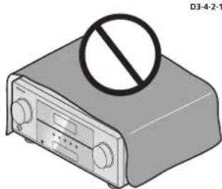
- When installing this unit, make sure to put it on a level and stable surface.
Don't install it on the following places:
-on a color TV (the screen may disolor) - near a cassette deck (or close to a device that gives off a magnetic field). This may interfere with the sound.
in direct sunlight
-in camp or wet areas
in extremely hot or cold areas - in places where there is vibration or other movement
- in places that are very dusty
in places that have hot fumes or oils (such as a kilcher)
Flow of settings on the receiver
The unit is a full-fledged AV receiver equipped with an abundance of functions and terminals. It can be used easily after following the procedure below to make the connections and settings.
The colors of the steps indicate the following:
Required setting item
Setting to be made as necessary
1 Connecting the speakers
Where you place the speakers will have a big effect on the sound.
- Placing the speakers (page 10)
- Connecting the speakers (page 11)
- Switching the speaker system (page 12)

2 Connecting the compo
For surround sound, you'll want to hook up using a digital connection from the Blu-ray Disc/DVD player to the receiver.
About video outputs connection (page 13)
- Connecting a TV and playback components (page 14)
- Connecting antennas (page 18)
Plugging in the receiver (page 19)

3 Power On
Make sure you've set the video input on your TV to this receiver. Check the manual that came with the TV if you don't know how to do this.

4 The Pre Out Setting (page 37)
(When connecting the front height speakers.)
The Input Assign menu (page 36)
(When using connections other than the recommended connections.)
Using the Audio Return Channel function (page 38)
(When the connected TV supports the HDMI Audio Return Channel function.)

5 Use the on-screen automatic MCACC setup to set up your system
Automatically setting up for surround sound (MCACC) (page 20):

6 Playing a source (page 22)
- Selecting the audio input signal (page 22)
- Playing an iPod (page 23)
- Playing a USB device (page 24)
- Choosing the listening mode (page 29)

7 Adjusting the sound as desired
Using the Sound Retriever (page 30)
- Belter sound using Phase Control (page 31)
- Listening with Acoustic Calibration EQ (page 30)
- Using surround back channel processing (page 31)
- Setting the Up Mix function (page 31)
- Setting the Audio options (page 32)
- Manual speaker setup (page 34)

8 Making maximum use of the remote control
- Siting the remote to control other components (page 40):
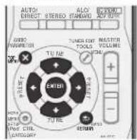
Chapter 1: Controls and displays
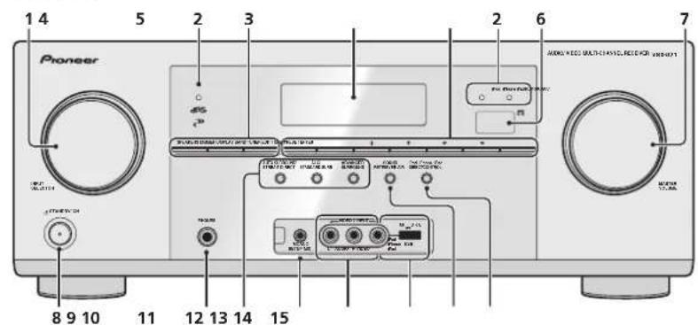
Front panel
1 INPUT SELECTOR dial
Selects an input source (page 22).
2 indicators
MCACC - Lights when Acoustic Calibration EQ (page 30) is on (Acoustic Calibration EQ is automatically set to on after the Auto MCACC setup (page 20)).
HDMI - Blinks when connecting an HDMI-equipped component; lights when the component is connected (page 14).
iPod iPhone iPad - Lights when an iPod/iPhone/Pad is connected and iPod USB input is selected (page 19).
3 Receiver control buttons
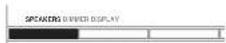
SPEAKERS - Use to change the speaker system (page 12).
DIMMER - Dims or brightons the display. The brightness can be controlled in four steps.
DISPLAY - Switches the display of this unit. The listening mode, sound volume, Pre Out setting or input name can be checked by selecting an input source.
- The Pre Cut setting may or may not be displayed, depending on the input source you have selected.
4 Character display
See Display on page 7.
5 Tuner control buttons
BAND-Switches between AM,FM ST (stereo) and FM MCNO radio bands page 28.
TUNER EDIT - Use with TUNE ↑/↓, PRESET ←/→ and ENTER to memorize and name slations for recall (page 28). Used to preset the channel in SIRIUS Radio (page 27).
TUNE ↑/↓ - Used to find radio frequencies (page 28) and SIRIUS Radio channels (page 27).
PRESET ← / → -Use lo select preset radio stations
(page 28) and to select SIRUS Radio channels (page 27).
6 Remote sensor
Receives the signal(s) from the remote control (see Operating range of remote control or page 9).
7 MASTER VOLUME dial
8 STANDBY/ON
9 PHONES jack
Use to connect headphones. When the headphones are connected, there is no sound output from the speakers. The listening mode when the sound is heard from the headphones
STEREO ALC mode (S.R AIR mode can be also selected with ADAPTER input).
Controls and displays
10 Listening mode buttons
AUTO SURROUND/STREAM DIRECT - Switches between Auto surround mode (page 29) and Stream Direct playback (page 30).
ALC/STANDARD SURR - Press for standard decoding and to switch between the modes of Pro Logic II, Pro Logic IIx, Pro Logic IIz and NEO-6, and the Auto level control stereo mode (page 29).
ADVANCED SURROUND - Switches between the various surround modes (page 30).
11 MCACC SETUP MIC jack
Use to connect a microphone when performing Auto MCACC setup (page 20).
12 AUDIO/VIDEO input terminal
See Connecting to the front panel video terminal on page 18.
13 iPod iPhone iPad/USB terminal
Use to connect your Apple iPod or USB mass storage device as an audio source (page 19).
14 SOUND RETRIEVER AIR
When the button is pressed, the input switches to ADAPTER and the listening mode is automatically set to S.R AIR (page 26).
15 iPod iPhone iPad DIRECT CONTROL
Change the receiver's input to the iPod and enable iPod operations on the iPod (page 24).
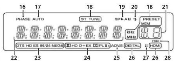
Display
16 PHASE
Lights when the Phase Control is switched on (page 31).
17 AUTO
Lights when the Auto Surround feature is switched on (page 29).
18 Tuner/SIRIUS indicators
ST-Lights when a stereo FM broadcast is being received in auto stereo mode (page 28).
TUNE - Lights when a normal broadcast channel or SIRIUS channel is being received.
PRESET - Shows when a preset radio station is registered or called.
MEM-Blinks when a radio station is registered
kHz/MHz - Lights when the character display is showing the currently received AM/FM broadcast frequency.
19 Speaker indicators
Lights to indicate the current speaker system, A and/or B (page 12).
20 Sleep timer indicator
Lights when the receiver is in sleep mode (page 8).
21 PRESET information or input signal indicator
Shows the preset number of the tuner or the input signal type, etc.
22 Character display
Displays various system information
23 DTS indicators
DTS = Lights when a source with DTS encoded audio signal is detected.
HD - Lights when a source with DTS-EXPRESSION or DTS-HD encoded audio signals is detected.
ES-Lights to indicate DIS-ES decoding.
96/24 - Lights when a source with DTS 96/24 encoded audio signals is detected.
NEO:6 - When one of the NEO:6 modes of the receiver is on, this lights to indicate NEO:6 processing (page 29).
24 Dolby Digital indicators
D-Lights when a Dolby Digital encoded signal is deleted.
- Lights when a source with Dolby Digital Plus encoded audio signals is detected.
HD-Lights when a source with Dolby TrueHD encoded audio signals is detected.
EX-Lights to indicate Dolby Digital EX decoding.
DOLPI(x) - Lights to indicate Pro Logic II/IO Pro Logic IIx decoding. Light will go off during Pro Logic IIz
decoding (see Listening in surround sound on page 29 for more on this).
25 ADV.S.
Lights when one of the Advanced Surround modes has been selected (see Using the Advanced surround on page 30 for more on this).
26 SIGNAL SELECT indicators
DIGITAL-Lights when a digital audio signal is selected. Blinks when a digital audio signal is selected and selected audio input is not provided.
HDMI - Lights when an HDMI signal is selected. Blinks when an HDMI signal is selected and selected HDMI input is not provided.
27 Up Mix/DIMMER indicator
Lights when the Up Mix function is set to ON (page 31). Also, lights when DIMMER is set to off.
28 DIR.
Lights when the DIRECT or PURE DIRECT mode is switched on (page 30).
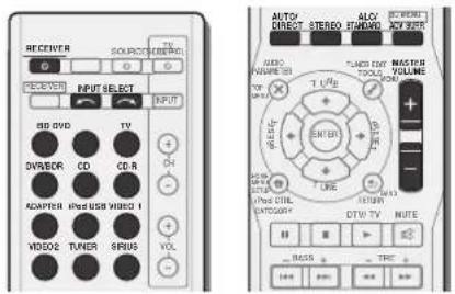
Remote control
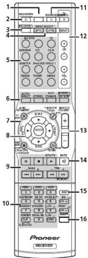
1 SLEEP
Press to change the amount of time before the receiver switches into standby (30 min - 60 min - 90 min - Off). You can check the remaining sleep time at any time by pressing SLEEP once.
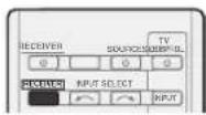
2 RECEIVER
Switches the receiver between standby and on.
3 RECEIVER
Switches the remote to control the receiver (used to select the white commands above the number buttons (MIDLIGHT, etc)). Also use this button to set up surround sound (page 34) or Audio parameters (page 32).
4 INPUT SELECT
Use to select the input source (page 22).
5 Input function buttons
Use to select the input source to this receiver (page 22). This will enable you to control other components with the remote control (page 40).
6 Listening mode buttons
AUTO/DIRECT - Switches between Auto surround mode (page 29) and Stream Direct playback (page 30).
STEREO - Press to select stereo playback (page 29).
ALC/STANDARD SURR - Press for standard decoding and to switch between the modes of Pro Logic II, Pro Logic II, Pro Logic II and NEO;6, and the Auto level control stereo mode (page 29).
ADV SURR - Switches between the various surround modes (page 30).
Press BD first to access:
BD MENU* - Displays the disc menu of Blu-ray Discs.
7 System Setup and component control buttons
The following button controls can be accessed after you have selected the corresponding input function button (BD, DVD, etc.).
Press RECEIVERcess:
AUDIO PARAMETER - Use to access the Audio options (page 32).
SETUP - Press to access the System Setup menu (page 34).
RETURN - Confirm and exit the current menu screen.
Press BD, DVD or DVR/BDR first to access:
TOP MENU - Displays the disc 'top' menu of a Blu-ray Disc/DVD.
HOME MENU - Displays the HOME MENU screen.
RETURN - Confirm and exit the current menu screen.
MENU-Displays the TOOLS menu of Blu-ray Disc player.
Press TUNER or SIRIUS first to access:
TUNER EDIT-Memorizes stallions for recall page 28
When TUNER is pressed, also used to change the name (page 28).
BAND - Switches between AM, FM ST (stereo) and FM MONO radio bands (page 28).
CATEGORY - Press to browse SIRIUS radio broadcasts. Press iPod USB first lo access:
iPod CTRL - Switches between the iPod controls and the receiver controls (page 24).
8 ↑/↓←/→ (TUNE ↑/↓, PRESET ←/→), ENTER
Use the arrow buttons when setting up your surround sound system (page 34). Also used to control Blu-ray Disc/DVD menus/options.
Use TUNE / can be used to find radio frequencies and PRESET ← → can be used to select preset radio slations (page 28).
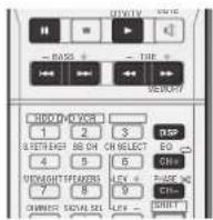
9 Component control buttons
The main buttons 一 , etc.) are used to control a component after you have selected it using the input function buttons.
The controls above these buttons can be accessed after you have selected the corresponding input function button (BD).
DVD. DVR/BDR and CD). These buttons also function as described below.
Press RECEIVERAccess
BASS-/+TRE-/+-Use to adjust Bass or Treble.
- Those controls are disabled when the listening mode is set to DIRECT or PURE DIRECT
Controls and displays
- When the front speaker is set as SMALL in the Speaker Setting (or automatically via the Auto MCACC setup) and the Crossover Network is set above 150 Hz, the subwoofer channel level will be adjusted by pressing BASS - / + page 35.
Press TV first to access:
DTV/TV - Switches between the DTV and analog TV input modes for Pioneer TVs.
10 Number buttons and other component controls
Use the number buttons to directly select a radio frequency (page 28) or the tracks on a CD, etc. There are other buttons that can be accessed after REeWERd. (For example MIDNIGHT, etc.)
HDD*DVD*VCR*These buttons switch between the hard disk, DVD and VCR controls for HDD/DVD/VCR recorders.
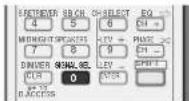
S.RETRIEVER - Press to restore CD quality sound to compressed audio sources (page 30).
SB CH -Press to select ON, AUTO or OFF the surround back channel (page 31).
CH SELECT - Press repeatedly to select a channel, then use LEV +/− to adjust the level (page 36).
LEV + / - Use to adjust the channel level.
EQ - Press to switch on/off Acoustic Calibration EQ setting (page 30).
MIDNIGHT - Switches to Midnight or Loudness listening (page 32).
SPEAKERS - Use to change the speaker system (page 12).
PHASE - Press to switch on/off Phase Control (page 31). DIMMER - Dims or brightens the display. The brightness can be controlled in four steps:
SIGNAL SEL - Press to select the audio input signal of the component to play back (page 22).
Press SIRIUS first to access:
D. ACCESS After pressing, you can access a radio station directly using the number buttons (page 27).
11 SOURCE
Press to turn on/off other components connected to the receiver (page 41).
12 TV CONTROL buttons
These buttons are dedicated to control the TV assigned to the TV button. Thus if you only have one TV to hook up to this system assign it to the TV button (page 41).
-Use to turn on/off the power of the TV.
INPUT - Use to select the TV input signal.
CH+/-Use to select channels.
VOL +/- Use to adjust the volume on your TV.
13 MASTER VOLUME +/-
Use lo sel the listening volume.
14 MUTE
Mules/unmutes the sound.
15 DISP
Switches the display of this unit. The listening mode, sound volume, Pre Out setting or input name can be checked by selecting an input source.
- The Pre Cut setting may or may not be disassembled, depending on the input source you have selected.
16SHIFT
Press to access the 'boxed' commands (above the buttons) on the remote. These buttons are marked with an asterisk (*) in this section.
Loading the batteries
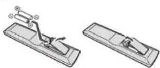
The batteries included with the unit are to check initial operations; they may not last over a long period. We recommend using alkaline batteries that have a longer life.
CAUTION
- Incorrect use of batteries may result in such hazards as leakage and bursting. Observe the following precautions:
Never use new and old batteries together
- Insert the pus and minus sides of the batteries properly according to the marks in the battery case.
Ballics with the same shape may have different voltages. Do not use different batteries together.
-
When disposing of used batteries, please comply with governmental regulations or environmental public instruction's rules that apply in your country or area.
-
Do not use or store batteries in direct sunlight or other excessively hot place, such as inside a car or near a theater. This can cause batteries to leak, overheal, explode or catch fire. It can also reduce the life or performance of ballers.
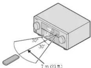
Operating range of remote control
The remote control may not work properly if:
There are obstacles between the remote control and the receiver's remote sensor.
- Direct sunlight or fluorescent light is shining onto the remote sensor.
The receiver is located near a device that is emitting infrared rays.
- The receiver is operated simultaneously with another infrared remote control unit.
Chapter 2: Connecting your equipment
Placing the speakers
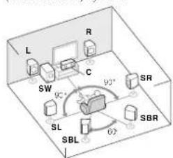
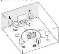
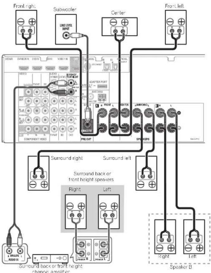
By connecting the left and right front speakers (L/R), the center speaker (C), the left and right surround speakers (SL/SR), and the subwoofer (SW), a 5.1 ch surround system can be enjoyed. Further, by using an external amplifier, you can connect the left and right surround back speakers (SBL/SBR) or the left and right front height speaker (FHL/FHR) to boost your system up to a 7.1 ch surround system.
- You can also connect one surround back speaker (SB) and enjoy a 6.1 ch surround system. To achieve the best possible surround sound, install your speakers as shown below.
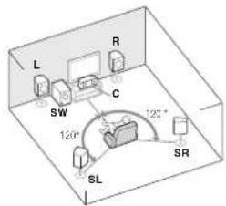
5.1 channel surround system:
7.1 channel surround (Surround back) system: a
6.1 channel surround (Surround back) system:
7.1 channel surround (front height) system: a
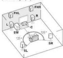
a. This layout is available only when the additional amplifier is connected to the unit and the surround back or front height speakers are connected to the amplifier. For details, see Connect the surround back or front height speakers on page 11.
Hints on the speaker placement
Where you put your speakers in the room has a big effect on the quality of the sound. The following guidencies should help you to get the best sound from your system.
- The subwoofer can be placed on the floor. Ideally, the other speakers should be at about ear-level when you're listening to them. Putting the speakers on the floor (except the subwoofer), or mounting them very high on a wall is not recommended.
For the best stereo effect, place the front speakers 2m to 3m (6 ft. to 9 ft.) apart; at equal distance from the TV. - If you're going to place speakers around your CRT TV, use shielded speakers or place the speakers at a sufficient distance from your CRT TV.
- If you're using a center speaker, place the front speakers at a wider angle. If not, place them at a narrower angle.
- Place the center speaker above or below the TV so that the sound of the center channel is localized at the TV screen. Also, make sure the center speaker does not cross the line formed by the leading edge of the front left and right speakers.
- It is best to angle the speakers towards the listening position. The angle depends on the size of the room. Use less of an angle for bigger rooms.
- Surround and surround back speakers should be positioned 60 cm to 90 cm (2 ft. to 3 ft.) higher than your ears and filled slight downward. Make sure the speakers don't face each other. For DVD-Audio, the speakers should be more directly behind the listener than for home theater playback.
- If the surround speakers cannot be set directly to the side of the listening position with a 7.1-channel system, the surround effect can be enhanced by turning off the Up Mix function (see Setting the Up Mix function on page 31).
- Try not to place the surround speakers farther away from the listening position than the front and center speakers. Doing so can weaken the surround sound effect.
- Place the left and right front height speakers at least one meter directly above the left and right front speakers.

CAUTION
- Make sure that all speakers are securely installed. This not only improves sound quality, but also reduces the risk of damage or injury resulting from speakers being knocked over or falling in the event of external shocks such as earthquakes.

Important
- To connect the surround back or front height speakers, an additional amplifier is required. Connect the additional amplifier to the PRE OUT SURR BACK/FRONT HEIGHT outputs of this unit and connect the surround back or front height speakers to the additional amplifier (see Connect the surround back or front height speakers on page 11).
Connecting your equipment
Connecting the speakers
The receiver will work with just two stereo speakers (the front speakers in the diagram) but using at least three speakers is recommended, and a complete setup is best for surround sound.
Make sure you connect the speaker on the right to the right (R) terminal and the speaker on the left to the left (L) terminal. Also make sure the positive and negative (+/-) terminals on the receiver match those on the speakers.
You can use the speakers connected to the B speaker terminals to listen to stereo playback in another room. See Switching the speaker system on page 12 for the listening options with this setup.
You can use speakers with a normal impedance between 6Ω and 16Ω.
However, note that only the front speakers are set to a value between 12Ω and 16Ω if you select SP▶AB in Switching the speaker system on page 12.
Be sure to complete all connections before connecting this unit to the AC power source.
Bare wire connections
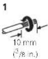
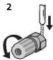
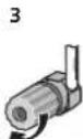
1 Twist exposed wire strands together.
2 Loosen terminal and insert exposed wire.
3 Tighten terminal.
CAUTION
- These speaker terminals carry HAZARDOUS LIVE voltage. To prevent the risk of electric shock when connecting or disconnecting the speaker cables, disconnect the power cord before touching any uninsulated parts.
- Make sure that all the bare speaker wire is twisted together and inserted fully into the speaker terminal. If any of the bare speaker wire touches the back panel it may cause the power to cut off as a safety measure.
Connect the surround back or front height speakers
Connect the PRE OUT SURR BACK/FRONT HEIGHT outputs of the unit and additional amplifier to add a surround back or front height speaker.
The Pre Out setting must be set if the above connections are performed. Select SURR.Back if the surround back speaker is connected and HEIGHT if the front height speaker is connected (if neither the surround back speaker nor the front height speaker is connected, either setting will suffice) (see The Pre Out Selling on page 37).
- You can use the additional amplifier on the surround back channel pre-outs for a single speaker as well. In this case plug the amplifier into the left (L (Single)) terminal only.
Switching the speaker system
Three speaker system settings are possible using the SPEAKERS button.
- Use the SPEAKERS button on the front panel to select a speaker system setting.
Press repealedly to choose a speaker system option:
- SP▶A - Sound is output from the speakers connected to the A speaker terminals and PRE OUT SURR BACK/
FRONTHEIGHT (multichannel playback is possible). - SP▶B - Sound is output from the two speakers connected to speaker system B (only stereo paack is possible).
SPB-AB-Sound is output from speaker system A, the two speakers in speaker system B, and the subwoofer. Multichannel sources are downmixed only when the STEREO or STEREO ALC mode is selected for stereo output from speaker systems A and B. - SP - No sound is output from the speakers.
Note
The subwoofer output depends on the settings you made in Speaker Setting on page 34. However, if SP> B is selected above, no sound is heard from the subwoofer (the LFE channel is not downmixed).
- You can use speakers with a normal impedance between 6Ω and 16Ω. However, be aware that only the front speakers are set to a value between 12Ω and 16Ω when you select SP>AB.
Making cable connections
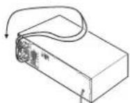
Make sure not to bend the cables over the top of this unit (as shown in the illustration). If this happens, the magnetic field produced by the transformers in this unit may cause a humming noise from the speakers.
Important
Before making or changing connections, switch off the power and disconnect the power cord from the AC outlet. Before unplugging the power cord, switch the power into standby.
HDMI cables
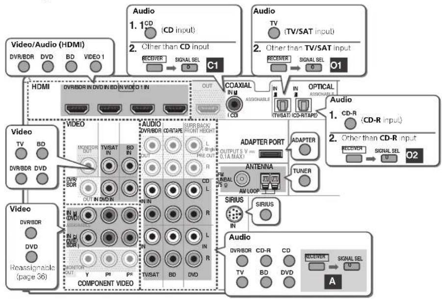
Bohn video and sound signals can be transmitted simultaneously with one cable, if connecting the player and the TV via this receiver, for both connections, use HDMI cables.
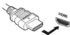
Be careful to connect the terminal in the proper direction.
Note
Sel the HDMI parameter in Setting the Audio options on page 32 to THRU (II) (ROUGI) and set the input signal in Selecting the audio input signal on page 22 to HDMI, if you want to hear HDMI audio output from your TV (no sound will be heard from this receiver).
If the video signal does not appear on your TV, try adjusting the resolution settings on your component or display. Note that some components (such as video game units) have resolutions that may not be displayed. In this case, use a (analog) composite connection.
- When the video signal from the HDMI is 480i, 480p, 576i or 576p, Multi Ch PCM sound and HD sound cannot be received.
About HDMI
The HDMI connection transfers uncompressed digital video, as well as almost every kind of digital audio that the connected component is compatible with, including DVD-Video, DVD-Audio, SACD, Dolby Digital Plus, Dolby TrueHD, DTS-HD Master Audio (see below for limitations), Video CD/ Super VCD and CD.
This receiver incorporates High-Definition Multimedia Interface (HDMI®) technology.
This receiver supports the functions described below through HDMI connections.
- Digital transfer of uncompressed video (contents protected by HDCP (1080p/24, 1080p/60, etc.))
- 3D signal transfer
- Deep Color signal transfer
x.v.Color signal transfer
Audio Return Channel - Input of multi-channel linear PCM digital audio signals (192 kHz or less) for up to 8 channels
- Input of the following digital audio formats:
-Dolby Digital, Dolby Digital Plus, DTS, High b-trate audio (Dolby TrueHD, DTS-HD Master Audio), DVD, CD, SACD (DSD 2 ch only), Video CD, Super VCD - Synchronized operation with components using the Control with HDMI function (see Control with HDMI function on page 38);
Note
- Use a High Speed HDMI cable. If HDMI cable other than a High Speed HDMI cable is used, it may not work properly.
- When an HDMI cable with a built-in equalizer is connected, it may not operate properly.
Connecting your equipment
- 3D. Deep Color, x.v.Color signal transfer and Audio Return Channel are only possible when connected to a compatible component.
- HDMI format digital audio transmissions require a longer time to be recognized. Due to this, interruption in the audio may occur when switching between audio formats or beginning playback.
- Turning on/off the device connected to this unit's HDMI OUJ terminal during playback, or disconnecting/ connecting the HDMI cable during playback, may cause noise or interrupted audio.
HDMI, the HDMI Logo and High-Definition Multimedia Interface are trademarks or registered trademarks of HDMI Licensing, LLC in the United States and other countries.
"X.v.Color" and are wColor of Sony Corporation.
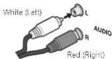
Analog audio cables
Use stereo RCA phone cables to connect analog audio components. These cables are typically red and white, and you should connect the red plugs to R (right) terminals and white plugs to L (left) terminals.
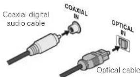
Digital audio cables
Commercially available coaxial digital audio cables or optical cables should be used to connect digital components to this receiver.
Video cables
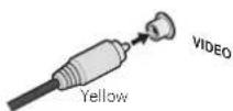
Standard RCA video cables
These cables are the most common type of video connection and are used to connect to the composite video terminals. The yellow plugs distinguish them from cables for audio,
Component video cables
Use component video cables to get the best possible color reproduction of your video source. The color signal of the TV is divided into the luminance (Y) signal and the color (Pb and PR) signals and then output. In this way, interference between the signals is avoided.

About video outputs connection
This receiver is not loaded with a video converter. When you use component video cables or HDMI cables for connecting to the input device, the same cables should be used for connecting to the TV.
The signals input from the analog (composite and component) video inputs of this unit will not be output from the HDMI OUT.

Terminal for connection with source device

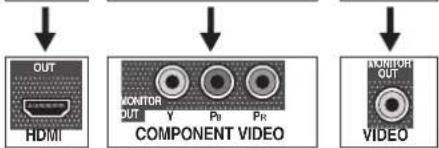
Terminal for connection with TV monitor

Connecting a TV and playback components
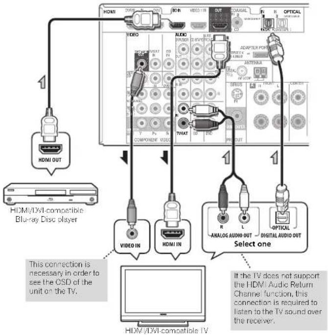
Connecting using HDMI
If you have an HDMI or DVI (with HDCP) equipped component (Blu-ray Disc player, etc.), you can connect it to this receiver using a commercially available HDMI cable.
If the TV and playback components support the Control with HDMI feature, the convenient
Control with HDMI functions can be used (see Control with HDMI function on page 38). The following connection/setting is required to listen to the sound of the TV over this receiver.
If the TV does not support the HDMI Audio Return Channel function, connect the receiver and TV with audio cables (as shown).
If the TV supports the HDMI Audio Return Channel function, the sound of the TV is input to the receiver via the HDMI terminal, so there is no need to connect an audio cable. In this case, set ARC at HDMI Setup to ON (see HDMI Setup on page 38).

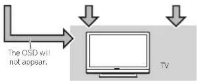
Important
If the receiver is connected to a TV using an HDMI cable, the on-screen display (OSD) will not be displayed. Be sure to use a standard RCA analog video cable to connect. In this case, switch the TV input to analog to see the OSD screen (for setup, etc.) on the TV.
- When the Control with HDMI function is ON and the receiver is connected to a compatible TV with an HDMI cable, and you switch the input of the TV to composite or component, the input of the receiver may automatically switch to TV/SAT. If this happens, switch the receiver's input back to the original input, or turn OFF the Control with HDMI function (see HDMI Setup on page 38).
Connecting your equipment
Connecting your component with no HDMI terminal
This diagram shows connections of a TV and DVD player (or other playback component) with no HDMI terminal to the receiver.
- If both TV and player has a component videoacks: you can connect these too. See Using the component videoacks on page 16 for more on this.
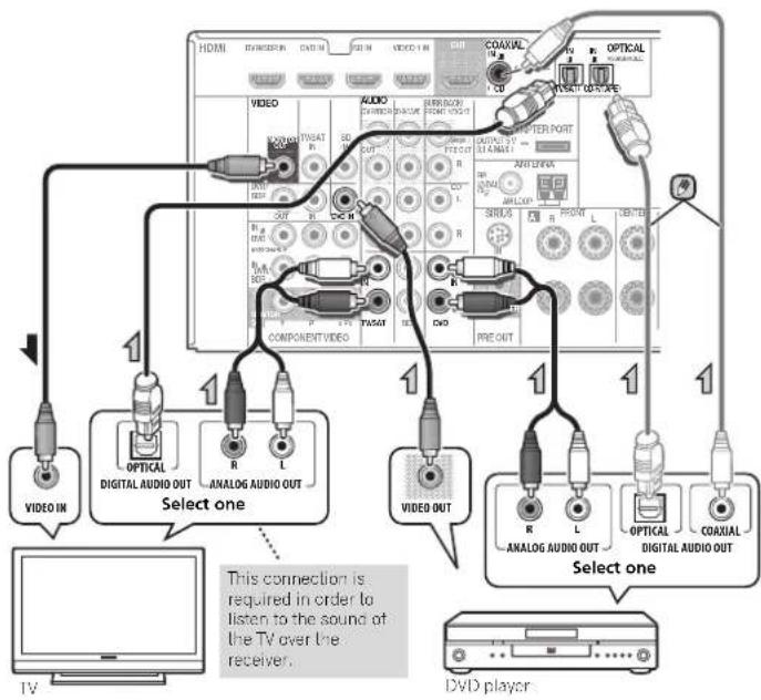
Note
In order to listen to the audio from the DVD player that is connected to this receiver using an optical cable or a coaxial cable, first, switch to the DVD input, then use RECEIVER and SIGNAL SEL to choose the audio signal O2 (OPTICAL2) or C1 (COAXIAL1) (see Selecting the audio input signal on page 22).
Connecting a satellite receiver or other digital set-top box
Satellite and cable receivers, and terrestrial digital TV tuners are all examples of so-called 'settopoosks'.
If the set-top box or video component also has an HDMI or a component video output, you can connect this too. See Connecting using HDMI on page 14 or Using the component video jacks on page 16 for more on this.
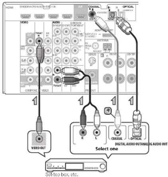
Note
- In order to listen to the audio from the source component that is connected to this receiver using a coaxial cable, first, switch to the TV/SAT, then use [RECEIVER] and SIGNAL SEL to choose the audio signal C1 (COAXIAL) (see Selecting the audio input signal on page 22).
Connecting an HDD/DVD recorder, Blu-ray Disc recorder and other video sources
This receiver has audio/video inputs and outputs suitable for connecting analog or digital video recorders, including HDD/DVD recorders and Blu-ray Disc recorders.
Only the signals that are input to theVIDEO IN terminal can be output from theVIDEO OUT terminal.
Audio signals that are input through the digital terminal will not be output from the analog terminal.

Note
In order to listen to the audio from the source component that is connected to this receiver
using an optical cable first switch to the DVR/ BDRinput then use RECEIVER SIGNAL SEL to choose the audio signal O2 (OPTICAL2) (see Selecting the audio input signal on page 22).
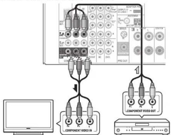
Using the component video jacks
Component video should deliver superior picture quality when compared to composite video. A further advantage (if your source and TV are both compatible) is progressive-scan video, which delivers a very stable, flicker-free picture. See the manuals that came with your TV and source component to check whether they are compatible with progressive-scan video.
For the audio connection, refer to Connecting your component with no HDMI terminal on page 15.

Important
- If you connect any source component to the receiver using a component video input, you must also have your TV connected to this receiver's COMPONENTVIDEO MONITOR OUT JACKS.
- If necessary, assign the component video inputs to the input source you've connected. This only needs to be done if you didn't connect according to the following defaults:
COMPONENTVIDEOIN1:DVD
COMPONENTVIDEOIN2:DVR/BDR
See The Input Assign menu on page 36 for more on this.
DVD player
Connecting your equipment
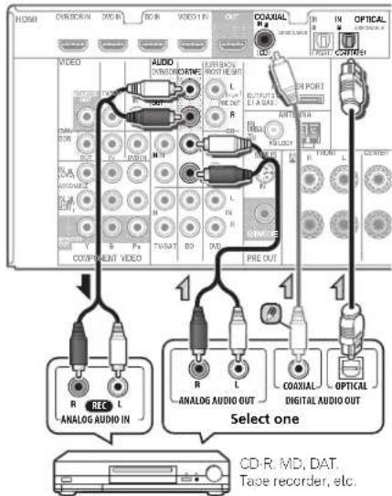
Connecting other audio components
The number and kind of connections depends on the kind of component you're connecting. Follow the steps below to connect a CD-R, MD, DAT, tape recorder or other audio component.
- Note that you must connect digital components to analog audio jacks if you want to record lo/from digital components (like an MD) to/from analog components.
Note
In order to listen to the audio from the CD player that is connected to this receiver using a coaxial cable, first, switch to the CD-R input, then use [RECEIVER] and SIGNAL SEL to choose the audio signal C1 (COAXIAL1) (see Selecting the audio input signal on page 22).
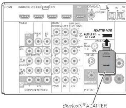
Connecting optional Bluetooth® ADAPTER
When the Bluetooth ADAPTER (Pioneer Model No. AS-BT100 or AS-BT200) is connected to this unit, a product equipped with Bluetooth wireless technology (portable cell phone, digital music player, etc.) can be used to listen to music wirelessly.
- Connect a Bluetooth ADAPTER to the ADAPTER PORT terminal on the rear panel.
- For instructions on playing the Bluetooth wireless technology device, see Paining the Bluetooth ADAPTER and Bluetooth wireless technology device on page 26.
Important
- Do not move the receiver with the Bluetooth ADAPTER connected. Doing so could cause damage or faulty contact.
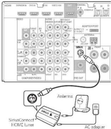
Connecting your SiriusConnect™ Tuner
To receive SIRIUS Safelite Radio broadcasts, you will need to activate your SiriusConnect tuner.
- Connect a SiriusConnect tuner to the SIRIUS IN jack on the rear panel.
- You will also need to connect the antenna and AC adaptor to the SiriusConnect tuner.
- For instructions on playing the SIRIUS Radio, see Listening to SIRIUS Radio on page 27.
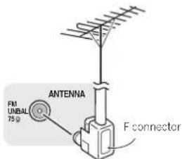
Connecting antennas
Connect the AM loop antenna and the FM wire antenna as shown below. To improve reception and sound quality, connect external antennas (see Using external antennas below).
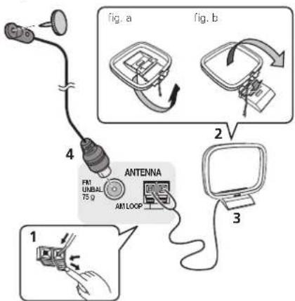
1 Push open the tabs, then insert one wire fully into each terminal, then release the tabs to secure the AM antenna wires.
2 Fix the AM loop antenna to the attached stand
To fix the stand to the antenna, bend in the direction indicated by the arrow (fig. a) then clip the loop onto the stand (fig. b).
3 Place the AM antenna on a flat surface and in a direction giving the best reception.
4 Connect the FM wire antenna into the FM antenna socket.
For best results, extend the FM antenna fully and fix to a wall or door frame. Don't drape loosely or leave coiled up.
Using external antennas
To improve FM reception
Use an F connector (not supplied) to connect an external FM antenna.
To improve AM reception
Connect a 5 m to 6 m (16 ft. to 20 ft.) length of vinyl-coated wire to the AM antenna terminal without disconnecting the supplied AM loop antenna.
For the best possible reception, suspend horizontally outdoors.

Connecting to the front panel video terminal
Front video connections are accessed via the front panel using the INPUT SELECTOR or VIDEO2 button on the remote control. There are standard audio/video jackets. Hook them up the same way you made the rear panel connections.
- Push down on the PUSH OPEN lab to access the front video connections.

Connecting your equipment
Connecting an iPod
This receiver has a dedicated iPod terminal that will allow you to control playback of audio content from your iPod using the controls of this receiver.
- Switch the receiver into standby, and then use the iPod cable to connect your iPod to the iPod terminal on the front panel of this receiver.
Push down on the PUSH OPEN tab to access the iPod terminal.
For the cable connection, refer to also the operating instructions for iPod.
For instructions on playing the iPod, see Playing an iPod on page 23.
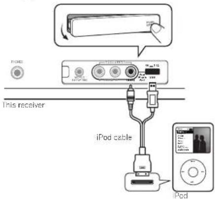
- When the Control with HDMI function is ON and the receiver is connected to a compatible TV with an HDMI cable, and you switch the input of the TV when the receiver's selection is iPod USB input, the receiver may automatically switch to TV/SAT. If this happens, switch the receiver's input back to the original input, or turn OFF the Control with HDMI function (see HDMI Setup on page 38).
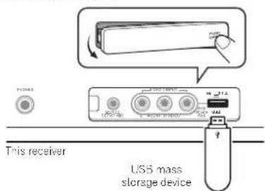
Connecting a USB device
It is possible to listen to two-channel audio using the USB interface on the front of this receiver.
-
Switch the receiver into standby then connect your USB device to the USB terminal on the front panel of this receiver.
-
Push down on the PUSH OPEN tab to access the USB terminal.
This receiver does not support a USB hub.
For instructions on playing the USB device, see Playing a USB device on page 24.
Plugging in the receiver
Only plug in after you have connected all your components to this receiver, including the speakers.
Plug the AC power cord into a convenient AC power outlet.

CAUTION
- Handle the power cord by the plug part. Do not pull out the plug by Lugging The cord, and never touch the power cord when your hands are wet, as this could cause a short circuit or electric shock. Do not place the unit, a piece of furniture, or other object on The power cord or pinch the cord in any other way. Never make a knot in the cord or tie it with other cables. The power cords should be routed so that they are not likely to be stepped on. A damaged power cord can cause a fire or give you an electric shock. Check the power cord once in a while, if you find it damaged, ask your nearest Pioneer authorized independent service company for a replacement.
The receiver should be disconnected by removing the mains plug from the wall socket when not in regular use, e.g., when on vacation.
Note
After this receiver is connected to an AC outlet, a 2 second to 10 second HDMI initialization process begins. You cannot carry out any operations during this process. The HDMI indicator in the front panel display blinks during this process, and you can turn on this receiver once it has stopped blinking. When you set the Control with HDMI to OFF, you can skip this process. For details about the Control with HDMI feature, see Control with HDMI function on page 38.

Chapter 3: Basic Setup
Canceling the demo display
The display on the front panel shows various information (demo displays) when the receiver is not operating. You can turn off the demo display. For details, see The Fl Demo Mode menu on page 37.
The demo mode is canceled automatically when the Auto MCACC setup is performed (see below).
Automatically setting up for surround sound (MCACC)
The Auto Multi-Channel Acoustic Calibration (MCACC) setup measures the acoustic characteristics of your listening area, taking into account ambient noise, speaker size and distance, and tests for both channel delay and channel level. After you have set up the microphone provided with your system, the receiver uses the information from a series of test tones to optimize the speaker settings and equalization for your particular room.
CAUTION
The test tones used in the Auto MCACC setup are outo1 at high volume.
Important
The QSD will not appear if you have connected using the HDMI output to your TV. Use composite or connections for system setup.
- The Auto MCACC setup will overwrite any existing speaker sellings you've made.
- Before using the Auto MCACC setup, the iPod USB input should not be selected as an input source.
If you connected either the surround back speaker or the front height speaker, make sure that the Pre Out setting is correctly set before performing the Auto MCACC setup (see page 37). (Here is an explanation using the OSD screen for a surround back speaker connection.)

1 Switch on the receiver and your TV.
2 Switch the TV input to the input that connects this receiver to the TV through the corresponding composite or component cable.
3 Connect the microphone to the MCACC SETUP MIC jack on the front panel.
Make sure there are no obstacles between the speakers and the microphone.
If you have a tripod, use it to place the microphone so that it's about ear level at your normal listening position. Otherwise, place the microphone at ear level using a table or a chair.
4 Press Rendemote control, then press the
SETUP button.
The System Setup menu appears on your TV. Use ↑/↓/←/→ and ENTER on the remote control to navigate through the screens and select menu items. Press RETURN to exit the current menu.
-
Pres s SETUP at any time to exit the System Setup menu. If you cancel the Auto MCACC setup at any time, the receiver automatically exits and no settings will be made.
-
The screensaver automatically starts after three minutes of inactivity.
5 Select 'Auto MCACC' from the System Setup menu, then press ENTER.
- MIC IN blinks when the microphone is not connected to MCACC SETUP MIC jack.
Try to be as quiet as possible after pressing ENTER. The system outputs a series of test tones to establish the ambient noise level.
6 Follow the instructions on-screen.
Make sure the microphone is connected.
Make sure the subwoofer is on and the volume is turned up.
- When using surround back or front height speakers, turn on the power to the amplifier to which the surround back or front height speakers are connected, and adjust the sound level to the desired level.
See below for notes regarding background noise and other possible interference.
Basic Setup
7 Wait for the test tones to finish.
A progress report is displayed on-screen while the receiver outputs test tones to determine the speakers present in your setup. Try to be as quiet as possible while it's doing this.
For correct speaker settings, do not adjust the volume during the test tones.
8 Confirm the speaker configuration.
The configuration shown on-screen should reflect the actual speakers you have.

- With error messages (such as Too much ambient noise) select RETRY after checking for ambient noise (see Other problems when using the Auto MCACC setup below). If the speaker configuration displayed isn't correct, use ↑/↓ to select the speaker and ←/→ to change the setting. When you're finished, go to the next step. If you see an error message (ERR) in the right side column, there may be a problem with the speaker connection, if selecting RETRY doesn't fix the problem, turn off the power and check the speaker connections.
9 Make sure 'OK' is selected, then press ENTER.
If the screen in step 7 is left untouched for 10 seconds and ENTER is not pressed in step 8, the Auto MCACC setup will start automatically as shown.
A progress report is displayed on-screen while the receiver outputs more test lorres to determine the optimum receiver settings for channel level, speaker distance, and Accoustic Calibration EQ.
Again, try to be as quiet as possible while this is happening. It may take 1 to 3 minutes.
10 The Auto MCACC setup has finished! You return to the System Setup menu.
The settings made in the Auto MCACC setup should give you excellent surround sound from your system, but it is also possible to adjust these settings manually using the System Setup menu (starting on page 34).
Note
- Depending on the characteristics of your room, sometimes identical speakers with one sizes of around 12 cm (5 inches) will end up with different size settings. You can correct the setting manually using the Speaker Setting on page 34.
The subwoofer distance setting may be farther than the actual distance from the listening position. This setting should be accurate (taking delay and room characteristics into account) and generally does not need to be changed.
Other problems when using the Auto MCACC setup
If the room environment is not optimal for the Auto MCACC setup (too much background noise, echo off the walls, obstacles blocking the speakers from the microphone) the final settings may be incorrect. Check for household appliances (air conditioner, fridge, fan, etc.), that may be affecting the environment and switch them off if necessary. If there are any instructions showing in the front panel display, please follow them.
Some older TVs may interfere with the operation of the microphone. If this seems to be happening, switch off the TV when doing the Auto MCACC setup.
Chapter 4: Basic playback
Playing a source
Here are the basic instructions for playing a source (such as a DVD disc) with your home theater system.
1 Switch on your system components and receiver. Start by switching on the playback component (for example a DVD player), your TV and subwoofer (if you have one), then the receiver (press 心 RECEIVER).
Make sure the setup microphone is disconnected.
2 Switch the TV input to the input that connects this receiver.
For example, if you connected this receiver to theVIDEO jacks on your TV, make sure that theVIDEO input is now selected.
3 Press input function buttons to select the input function you want to play.
The input of the receiver will switch over, and you will be able to operate other components using the remote control. To operate the receiver, first press RECEIVER the remote control, then press the appropriate button to operate.
The input source can also be selected by using INPUT SELECT on the remote control, or by using the front panel INPUT SELECTOR dial. In this case, the remote control won't switch operational modes.
If you selected the proper input source and there is still no sound, select the audio input signal for playback (see Selecting the audio input signal below).
4 Press AUTO/DIRECT to select 'AUTO SURROUND' and start playback of the source.
If you're playing a Dolby Digital or DTS surround sound DVD disc, with a digital audio connection, you should hear surround sound. If you're playing a stereo source or if the connection is an analog audio connection, you will only hear sound from the front left/right speakers in the default listening mode.
It is possible to check on the front panel display whether or not a surround sound playback is being performed properly. When using a surround back speaker, DOD+PLIIx is displayed when playing Dolby Digital 5.1-channel signals.
and DTS+NEO:6 is displayed when playing DTS 5.1-channel signals.
When not using a surround back speaker, DOD is displayed when playing Dolby Digital signals.
If the display does not correspond to the input signal and listening mode, check the connections and settings.
Note
You may need to check the digital audio output settings on your DVD player or digital satellite receiver. It should be set to output Dolby Digital, DTS and 88.2 kHz/96 kHz PCM (2 channel) audio, and if there is an MPEG audio option, set this to convert the MPEG audio to PCM.
Depending on your DVD player or source discs, you may only get digital 2 channel stereo and analog sound. In this case, the receiver must be set to a multichannel listening mode if you want multichannel surround sound.
5 Use MASTER VOLUME to adjust the volume level.
Turn down the volume of your TV so that all sound is coming from the speakers connected to this receiver.
Selecting the audio input signal
The audio input signal can be selected for each input source. Once it is set, the audio input that was selected will be applied whenever you select the input source using the input function buttons.
Press Press Signal SEL to select the
audio input signal corresponding to the source component. Each press cycles through the following:
-
H - Selects an HDMI signal. H can be selected for BD. DVD, DVR/BDR or VIDE01 input. For other inputs, H cannot be selected.
-
When the HDMI option in Setting the Audio options on page 32 is set to THRU, the sound will be heard through your TV, not from this receiver.
A Selects the analog inputs.
- C1/01/02 - Selects the digital input. The coaxial 1 input is selected for C1, and the optical 1 or 2 audio input is selected for O1 or O2.
When H (HDMI) or C1/01/02 (digital) is selected and the selected audio input is not provided, A (analog) is automatically selected.
Note
VIDEO1 input is fixed to H (HDMI). It cannot be changed.
For the TV/SAT input, only A (analog) or C1/O1/O2 (digital) can be selected. However, if the ARC at HDMI Setup is set to ON, the input is fixed to H (HDMI) and cannot be changed.
- When set to H (HDMI) or C1/O1/O2 (digital), ☐ lights when a Dolby Digital signal is input and DTS lights when a DTS signal is input.
- When the H (HDM) is selected, the A and DIGITAL indicators are off (see page 7).
Basic playback
- When digital input (optical or coaxial) is selected, this receiver can only play back Dolby Digital, PCM (32 kHz to 96 kHz) and DTS (including DTS 96 kHz/24 bit) digital signal formats. The compatible signals via the HDMI terminals are: Dolby Digital, DTS, SACD (DSD 2 ch only), PCM (32 kHz to 192 kHz sampling frequencies), Dolby TrueHD, Dolby Digital Plus, DTS-EXPRESS, DTS-HD Master Audio and DVD Audio (including 192 kHz). With other digital signal formats, set to A (analog).
Tip
In order to enjoy the picture and/or sound from devices connected to each terminal, select the input by doing the following.
- You may get digital noise when a LD or CD player compatible with DTS is playing an analog signal. To prevent noise, make the proper digital connections (page 13) and set the signal input to C1/O1/O2 (digital).
Some DVD players don't output DTS signals. For more details, refer to the instruction manual supplied with your DVD player.
Playing an iPod
This receiver has a dedicated iPod terminal that will allow you to control playback of audio content from your iPod using the controls of this receiver.

Important
- Pioneer cannot under any circumstances accept responsibility for any direct or indirect loss arising from any inconvenience or loss of recorded material resulting from the iPod failure.
Note
This system is compatible with the audio and the video of the iPod nano, iPod (fifth generation), iPod classic, iPod touch and iPhone (only supports iPod (fifth generation) and iPod nano (first and second generation) audio playback) (iPod shuffle not supported). However, that some of the functions may be restricted for some models.
This receiver has been developed and tested for the software version of iPod/Phone/iPad indicated on the website of Pioneer.
- Installing software versions other than indicated on the website of Pioneer to your iPod/iPhone/iPad may result in incompatibility with this receiver.
- iPod and iPhone are licensed for reproduction of noncopyrighted materials or materials the user is legally permitted to reproduce.
- Features such as the equalizer cannot be controlled using this receiver, and we recommend switching the equalizer off before connecting.
1 Switch on the receiver and your TV.
See Connecting an iPod on page 19.
2 Switch the TV input to the input that connects this receiver to the TV through the corresponding composite or component cable.
3 Press iPod USB on the remote control to switch the receiver to the iPod USB input.
The front panel display shows Loading while the receiver verifies the connection and retrieves data from the IPod.
4 Use TOP MENU to display iPod Top menu.
When the display shows Top Menu you're ready to play music from the iPod.

If after pressing iPod the display shows NO DEVICE, try switching off the receiver and reconnecting the iPod to the receiver.
The controls of your iPod (excluding the iPod touch and Phone) will be inoperable when connected to this receiver (Pioneer shows in the iPod display).
Playing back files stored on an iPod
To navigate songs on your iPod, you can take advantage of The OSD of your TV connected to this receiver. You can also control all operations for music in the front panel display of this receiver.
Note that non-roman characters in the title are displayed as *
This feature is not available for photos or video clips on your iPod.
Finding what you want to play
When your iPod is connected to this receiver, you can browse songs stored on your iPod by playlist, artist, album name, song name, genre or composer, similar to using your iPod directly.
1 Use / to select a category, then press ENTER to browse that category.
To return to the previous level any time, press RETURN.
2 Use / to browse the selected category (e.g., albums).
- Use ← / → to move to previous/next levels.
3 Continue browsing until you arrive at what you want to play, then press to start playback.
Tip
If you're in the song category, you can also press ENTER to start playback.
- You can play all of the songs in a particular category by selecting the All item at the top of each category list. For example, you can play all the songs by a particular artist
Basic playback controls
This receiver's remote control buttons can be used for basic playback of files stored on an iPod.
- Press iPod USB to switch the remote control to the iPod/USB operation mode.
During Audiobook playback, press ↑/↓ to switch the playback speed: Faster → Normal → Slower
Watching photos and video content
To view photos or video on your iPod, since video control is not possible using this receiver, you must use the main controls of your iPod instead.
Important
- To play photos or video on your iPed, you must connect the composite monitor OUT jack and TV.
- iPod photos and video content can be viewed only when the iPod is connected to the iPod VIDEO input on the front panel.
- This feature can only be used with an iPod having video output.
1 Press iPod CTRL to switch to the iPod controls for photo and video playback.
The receiver controls will be unavailable while you are watching iPod videos or browsing photos.
2 Press iPod CTRL again to switch back to the receiver controls when you're done.
Tip
- Change the receiver's input to the iPod in one action by pressing iPod iPhone iPad DIRECT CONTROL on the front panel to enable iPod operations on the iPod.
Playing a USB device
It is possible to listen to two-channel audio using the USB interface on the front of this receiver.
Important
- Pioneer cannot guarantee compatibility (operation and/or bus power) with all USB mass storage devices and assumes no responsibility for any loss of data that may occur when connected to this receiver.
Note
This includes playback of WMA/MP3/MPEG-4 AAC files (except files with copy-protection or restricted playback)
- Compatible USB devices include external magnetic hard drives, portable flash memory (particularly keydrives) and digital audio players (MP3 players) of formal FAT16/32. It is not possible to connect this receiver to a personal computer for USB playback.
- With large amounts of data, it may take longer for the receiver to read the contents of a USB device.
If the file selected cannot be played back, this receiver automatically skips to the next file playable.
- When the file currently being played back has no title assigned to it, the file name is displayed in the OSD instead; when neither the album name nor the artist name is present, the row is displayed as a blank space.
Note that non-roman characters in the playlist are displayed as *
- Make sure the receiver is in standby when disconnecting the USB device.
1 Switch on the receiver and your TV.
See Connecting a USB device on page 19.
2 Switch the TV input to the input that connects this receiver to the TV through the corresponding composite or component cable.
3 Press iPod USB on the remote control to switch the receiver to the iPod USB input.
Loading appears in the OSD as this receiver starts recognizing the USB device connected. After the recognition, a playback screen appears in the OSD and playback starts automatically.
Basic playback
Basic playback controls
This receiver's remote control buttons can be used for basic playback of files stored on USB devices.
- Press iPod USB to switch the remote control to the iPod/USB operation mode.

Important
If a USB Error message lights in the display, try following the points below:
- Switch the receiver off, then on again.
- Reconnect the USB device with the receiver switched off.
- Select another input source (like BD), then switch back to
iPod USB
- Use a dedicated AC adapter (supplied with the device) for USB power.
For more information on error messages, see USB messages on page 46.
If this doesn't remedy the problem, it is likely your USB device is incompatible.
Compressed audio compatibility
Note that although most standard bit/sampling rate combinations for compressed audio are compatible, some irregularly encoded files may not play back. The list below shows compatible formats for compressed audio files:
- MP3 (MPEG-7/2/2.5 Audio Layer 3) - Sampling rates: 8 kHz to 48 kHz; Bit rates: 8 kbps to 320 kbps (128 kbps or higher recommended); file extension: .mp3
WMA (Windows Media Audio) - Sampling rates: 32 kHz/44.1 kHz; Bit rates: 32 kbps to 192 kbps (128 kbps or higher recommended); File extension: .wma; WMA9 Pro and WMA lossless encoding; No - AAC (MPEG 4 Advanced Audio Coding) - Sampling rates: 11,025 kHz to 48 kHz. Bit rates: 16 kbps to 320 kbps (128 kbps or higher recommended); File extension: .m4a; Apple lossless encoding: No
Other compatibility information
- V3R (variable bit rate) MP3/WMA/MPEG 4 AAC playback; Yes (Note Inal in some cases playback time will not be dispayed correctly.)
- DRV (Digital Rights Management) protection compatible: Yes (DRM protected audio files will not play in this receiver.)
About MPEG-4 AAC
Advanced Audio Coding (AAC) is at the core of the MPEG-4 AAC standard, which incorporates MPLG-2 AAC, forming the basis of the MPEG 4 audio compression technology. The file format and extension used depend on the application used to encode the AAC file. This receiver plays back AAC files encoded by iTunes® bearing the extension 'm4a'. DRM-protected files will not play, and files encoded with some versions of iTunes® may not play. Apple and iTunes are trademarks of Apple Inc., registered in the U.S. and other countries.
About WMA
WMA is an acronym for Windows Media Audio and refers to an audio compression technology developed by Microsoft Corporation. This receiver plays back WMA files encoded using Windows Media Player bearing the extension .wma'. Note that DRM-protected files will not play, and files encoded with some versions of Windows Media Player may not play.
Bluetooth® ADAPTER for Wireless Enjoyment of Music

Bluetooth wireless technology enabled device: cell phone

Bleuethow wireless technology enabled devices: Digital music player

Device not equipped with Bluetooth wireless technology: Digital music player + Bluetooth audio transmitter (sold commercially)

Wireless music play
When the Bluetooth ADAPTER (Pioneer Model No. AS-BT100 or AS-BT200) is connected to this unit, a product equipped with Bluetooth wireless technology (portable cell phone, digital music player, etc.) can be used to listen to music wirelessly. Also, by using a commercially available transmitter supporting Bluetooth wireless technology, you can listen to music on a device not equipped with Bluetooth wireless technology. The AS-BT100 and AS-BT200 model supports SCMS-T contents protection, so music can also be enjoyed on devices equipped with SCMS-T type Bluetooth wireless technology.
- It must be necessary that the Bluetooth wireless technology enabled device supports A2DP profiles.


Important
- Pioneer does not guarantee proper connection and operation of this unit with all Bluetooth wireless technology enabled devices.
Remote control operation
The remote control supplied with this unit allows you to play and stop media, and perform other operations.
- It must be necessary that the Bluetooth wireless technology enabled device supports AVRCP profiles.
Remote control operations cannot be guaranteed for all Bluetooth wireless technology enabled devices.
Pairing the Bluetooth ADAPTER and Bluetooth wireless technology device
"Pairing" must be done before you start playback of Bluetooth wireless technology content using Bluetooth ADAPTER. Make sure to perform pairing first time you operate the system or any time pairing data is cleared. "Pairing" is the step necessary to register Bluetooth wireless technology device to enable Bluetooth communications. For more details, see also the operating instructions of your Bluetooth wireless technology device.
- Pairing is required when you first use Bluetooth wireless technology device and Bluetooth ADAPTER.
- To enable Bluetooth communication, pairing should be done with both of your system and Bluetooth wireless technology device.
- If the Bluetooth wireless technology device's security code is "0000", there is no need to make the security code selling on the receiver. Press ADAPTER to switch the ADAPTER input, then conduct the pairing operation on the Bluetooth wireless technology device. If pairing is successful, there is no need to performing the pairing operation below.
- When using Inc AS-BT200 only; If the Bluetooth wireless technology device supports SSP (Secure Simp Carping), there is no need to make the security code setting. Press ADAPTER to switch the ADAPTER input, then conduct the pairing operation on the Bluetooth wireless technology device. If pairing is successful, there is no need to performing the pairing operation below.
1 Press TOP MENU.
2 Press ENTER to enter PAIRING.
3 Select the PIN code to be used from 0000/1234/8888 using ← / → then press ENTER.
PAIRINGblinks.
You can use any of 0000/1234/8588 PIN codes. Bluetooth wireless technology device using any other PIN code cannot be used with this system.
4 Switch on the Bluetooth wireless technology device that you want to make pairing, place it near the system and set it into the pairing mode.
5 Check to see that the Bluetooth ADAPTER is detected by the Bluetooth wireless technology device.
When Bluetooth wireless technology device is connected: Bluetooth wireless technology device name appears in the receiver display.
The system can display alphanumeric characters only.
Other characters may not be displayed correctly. When Bluetooth wireless technology device is not connected:
NODEVICE appears in the receiver display. In this case, perform the connection operation from the side of the Bluetooth wireless technology device.
6 From the Bluetooth wireless technology device list, select Bluetooth ADAPTER and enter the PIN code selected in the step 4.
PIN code may in some case be referred to as PASSKEY.
Listening to Music Contents of Bluetooth wireless technology device with Your System
1 Press ADAPTER to switch the receiver to ADAPTER input.
The ADAPTER input can also be selected by pressing SOUND RETRIEVER AIR on the front panel. In this case, S.R AIR, the optimum listening mode, is selected automatically.
2 Perform the connection operation from the side of the Bluetooth wireless technology device to the Bluetooth ADAPTER.
When the Bluetooth ADAPTER is not plugged into the ADAPTER PORT terminal, NO ADAPTER will be displayed if ADAPTER input is selected.
3 Start playback of music contents stored in Bluetooth wireless technology device.
This receiver's remote control buttons can be used for basic playback of files stored on the Bluetooth wireless technology device.
- Bluetooth wireless technology device should be compatible with AVRCP profile.
Depending on Bluetooth wireless technology device you use, operation may differ from what is shown in the remote control bullons.

The Bluetooth® word mark and logos are registered trademarks owned by Bluetooth SIG, Inc. and any use of such marks by Pioneer Corporation is under license. Other trademarks and trade names are those of their respective owners.
Listening to Satellite Radio
To listen to Satellite Radio, you'll need to connect a SIRIUS Satellite Radio tuned (sold separately) to your Sirius-Ready receiver. SIRIUS Satellite Radio is available to residents of the US (except Alaska and Hawaii) and Canada.
Satellite Radio delivers a variety of commercial-free music from categories ranging from Pop, Rock, Country, R&B, Dance, Jazz, Classical and many more plus coverage of all the too professional and college sports including play by play games from select leagues and teams. Additional programming includes expert sports talk, uncensored entertainment, comedy, family programming, local traffic and weather and news from your most trusted sources. Once you've purchased a SIRIUS tuner you'll need to activate it and subscribe to begin enjoying the service. Easy to follow installation and setup instructions are provided with the SIRIUS tuner. There are a variety of programming packages available, including the option of adding "The Best of XM"
Basic playback
programming to the SIRIUS service. The Best of XM service is not available to SIRIUS Canada subscribers at this time. Please check with SIRIUS Canada for any updates using the numbers and web address below.
Family friendly packages are also available to restrict channels featuring content that may be inappropriate for children.
To subscribe to SIRUS, U.S. and Canadian customers can call 1-888-639-SIRI (1-888-539-7474) or visit sirius.com (US) or siriuscanada.ca (Canada).
SIRIUS, XM and all related marks and logos are trademarks of Sirius XM Radio Inc. and its subsidiaries. All rights reserved.
Service not available in Alaska and Hawaii.
Listening to SIRIUS Radio
After connecting, you will be able to use this receiver to select channels using the front panel display.
Note
In order to activate your radio subscription, you will need the SIRIUS ID (SID) which uniquely identifies your tuner. The SID may be found on a sticker located on the packaging, or on the bottom of the tuner itself. The label will have a printed 12-digit SID number. When you have located the SID, write it down in the space provided near the end of this manual. Connect SIRIUS on the internet at: https://activalc.siriusradio.com Follow the prompts to activate your subscription, or you can also call SIRIUS toll-free at 1-888-539-SIRIUS (1-888-539-7474).
- Press SIRIUS to switch to the SIRIUS input.
For best reception, you may need to move the SiriusConnecttuner antenna near a window (refer to the manual for theSiriusConnectHome tuner for antenna placementrecommendations).
- If after pressing SIRIUS the display shows Antenna Error, try disconnecting the antenna and reconnecting. If the display shows Check Sirius Tuner, check the connection of the AC adapter and this receiver to the Sirius Connect Tuner.
- You can check the strength of reception by pressing DISP (DISPLAY).
Selecting channels and browsing by genre
Use the front panel display to select channels. You can select channels from your favorite genre.
- You can, however, use just the front panel display to do everything if you prefer.
Press / to select the channel. In the next 2 seconds, the radio broadcast is automatically tuned in.
To select a channel from your favorite genre, press CATEGORY and use ↔ to select a genre, and then use 14 and ENTER to select a channel from the selected genre. Select SRO00 (SIRIUS ID) from the front panel display to search the Audio ID of the SIRIUS Genre list.
To cancel and exit any time, press RETURN
Tip
- You can select channels directly by pressing D.ACCESS then the three-digit channel number.
- You can press DISP (DISPLAY) to change SIRIUS Radio information in the front panel display.
- The currently selected channel is automatically chosen (without pressing ENTER) after 2 seconds.
Saving channel presets
This receiver can memorize up to 30 channels, stored.
1 Select the channel you want to memorize.
See Selecting channels and browsing by genre above.
2 Press T.EDIT.
The display shows a blinking memory number.
3 Press ← / → to select the channel preset you want. You can also use the number buttons to select a preset.
4 Press ENTER.
After pressing ENTER, the preset number stop blinking and the receiver stores the SIRIUS channel.
Listening to channel presets
You will need to have some presets stored to do this.
- Press ← / → to select the channel preset you want.
- You can also use the number buttons on the remote control to recall the channel preset.
Using the SIRIUS Menu
The SIRIUS Menu provides additional SIRIUS Radio features.
1 Press TOP MENU.
2 Use / to select a menu item then press ENTER.
Choose between the following menu items:
- All CHANNEL SKIP CLEAR - Clear the channel skip function set by the SiriusConnect tuner. If the channel skip function is not cleared here, not all channels are displayed because this receiver stores the channels set for skipping in the SiriusConnect tuner.
- Parental Lock - Use ↑/↓ and ENTER to select channels you would like to place under parental lock. Channels put under parental lock are not displayed in the Channel Guide, but may be accessed by directly inputting their channel number and providing the parental lock password.
- Password Set - Set the parental lock password.
3 When you're finished press TOP MENU to return to the reception display.
- You can reset the channel presets, parental lock and Password Set in Resetting the main unit on page 46.
Listening to the radio
The following steps show you how to tune in to FM and AM radio broadcasts using the automatic (search) and manual (step) tuning functions. Once you are tuned to a station you can memorize the frequency for recall later—see Saving station presets below for more on how to do this.

1 Press TUNER to select the tuner.
2 Use BAND to change the band (FM or AM), if necessary. Each press switches the band between FM (stereo or mono) and AM.
3 Tune to a station.
There are three ways to do this:
Automatic tuning
To search for stations in the currently selected band, press and hold TUNE for about a second. The receiver will start searching for the next station, stopping when it has found one. Repeat to search for other slantions.
Manual tuning
To change the frequency one step at a time, press TUNE ↑/↓.
High speed tuning
Press and hold TUNE ↑/↓ for high speed tuning.
Release the bullon at the frequency you want.
Improving FM sound
If the TUNE or ST indicators don't light when tuning to an FM station because the signal is weak, set the receiver to the mono reception mode.
Press BAND to select FM MONO.
This should improve the sound quality and allow you to enjoy the broadcast.
Saving station presets
If you often listen to a particular radio station, it's convenient to have the receiver store the frequency for easy recall whenever you want to listen to that station. This saves the effort of manually tuning in each time. This unit can memorize up to 30 stallions.
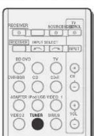
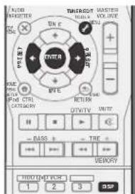
1 Tune to a station you want to memorize.
See Listening to the radio on page 28 for more on this.
2 Press TUNER EDIT.
The display shows PRESET, then a blinking MEM and station preset.
3 Press PRESET ← / → to select the station preset you
want.
You can also use the number buttons.
4 Press ENTER.
The preset number stop blinking and the receiver stores the station.
Note
If the receiver is left disconnected from the AC power outlet for over a month, the station memories will be lost and will have to be reprogrammed.
- Stalions are stored in stereo. When the stalion is stored in the FM MONO mode, it shows as ST when recalled.
Listening to station presets
You will need to have some presets stored to co this. See Saving station presets above if you haven't done this already.
- Press PRESET ← / → to select the station preset you want.
- You can also use the number buttons on the remote control to recall the station preset.
Naming preset stations
For easier identification, you can name all of your preset stations.
1 Choose the station preset you want to name.
See Listening to station presets above for how to do this.
2 Press TUNER EDIT twice.
The cursor at the first character position is blinking on the display.
3 Input the name you want.
Choose a name up to eight characters long.
- Use PRESET ← / → to select character position.
Use TUNE / to select characters.
The name is stored when ENTER is pressed.
Tip
To erase a station name, follow steps 1 and 2, and press
ENTER while the display is blank. Press TUNER EDIT
while the display is blank, to keep the pre
Once you have named a station preset, Press DISP to show the name. When you want to return to the frequency display, press DISP several times to show the frequency.
Listening to your system
Chapter 5: Listening to your system
Choosing the listening mode
This receiver offers a variety of listening modes to accommodate playback of various audio formats. Choose one according to your speaker environment or the source.
While listening to a source, press the listening mode button repeatedly to select a listening mode you want.
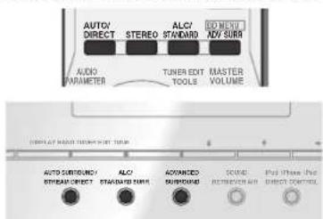
The listening mode is shown on the display on the front panel.
Important
The listening modes and many features described in this section may not be available depending on the current source, settings and status of the receiver.
Auto playback
The simplest, most direct listening option is the AUTO SURROUND feature. With this, the receiver automatically detects what kind of source you're playing and selects mulichannel or stereo playback as necessary.
- Press AUTO/DIRECT repeatedly until AUTO SURROUND shows briefly in the display (it will then show the decoding or playback format). Check the digital format indicators in the display to see how the source is being processed.
4 Note
- Stereo surround (matrix) formats are decoded accordingly using NEO:6 CINEMA or DOLBY PLIIx MOVIE (see Listening in surround sound below for more on these decoding formats).
- When listening to the ADAPTER input, the S.R AIR feature is selected automatically (see Using the Advanced surround on page 30 for more on this).
Listening in surround sound


Using this receiver, you can listen to any source in surround sound. However, the options available will depend on your speaker setup and the type of source you're listening to.
- If the source is Dolby Digital, DTS, or Dolby Surround encoded, the proper decoding format will automatically be selected and shows in the display.
When you select STEREO ALC (Auto Level Control stereo mode), this unit equalizes playback sound levels if each sound level varies with the music source recorded in a portable audio player.
When you select STEREO, you will hear the source through just the front left and right speakers (and possibly your subwoofer depending on your speaker settings). Dolby Digital and DTS multichannel sources are downmixed to silco.
The following modes provide basic surround sound for stereo and multichannel sources. Explanatory notes
No: No connected / Yes: Connected / Two: Two speakers are connected / -; Whether connected or no
| Type of surround modes | Suitable sources | Surround back speaker(s) | From height speakers |
| Two channel sources | |||
| STEREO ALC See above. -- | |||
| DOLBY PLIIx MOVIE Movie | Yesa | No | |
| DOLBY PLII MOVIE No - | |||
| DOLBY PLIIx MUSICb | Music | Yesa | No |
| DOLBY PLII MUSICb | No | - | |
| DOLBY PLIIx GAME Video games | Yesa | No | |
| DOLBY PLII GAME No - | |||
| DOLBY PLIIZ HEIGHTc | Movie/Music | No | Yes |
| NEO:6 CINEMAd | Movie | -- | |
| NEO:6 MUSICd | Music | -- | |
| DOLBY PRO LOGIC | Old movies | -- | |
| Straight Doodlee | No additional effects | No - | |
| STEREOSf | See above. -- | ||
| Multichannel sources | |||
| STEREO ALC See above. -- | |||
| DOLBY PLIIx MOVIE Movie | Twoa | No | |
| DOLBY PLII MOVIE No - | |||
| DOLBY PLIIx MUSICb | Music | Twoa | No |
| DOLBY PLII MUSICb | No | - | |
| DOLBY DIGITAL EX | Movie/Music | Yes | No |
| DTS-ES | Movie/Music | Yes | No |
| DTS NEO:6 | Movie/Music | Yes | No |
| DOLBY PLIIZ HEIGHT | Movie/Music | No | Yes |
| Straight Decodee | No additional effects | -- | |
| STEREOSf | See above. -- | ||
a. If surround back channel processing (page 31) is switched off, or the surround back speakers are set to NO DOLBY PLIIx becomes DOLBY PLII (5.1 channel sound).
b. You can also adjust the C.WIDTH, DIMEN., and PNRM. effect (see Setting the Audio options or page 32):
c. You can also adjust the H.GAIN effect (see Setting the Audio Options on page 37).
d. You can also adjust the CIMG effect (see Setting the Audio options on page 32).
e. Cannot be seected when the Pre Out is set to Surr. Back (see The Pre Out Setting on page 37).
f. You can choose the STEREO mode by using STEREO button on the remote control. The audio is heard with your surround settings and you can still use the Midnight Loudness Phase Control, Sound Retriever and Tone functions.
Note
- In modes that give 6.1 channel sound, the same signal is heard from both surround back speakers.
Using the Advanced surround


The Advanced surround feature creates a variety of surround effects. Try different modes with various soundtracks to see which you like.
ACTION Designed for action movies with dynamic soundtracks.
DRAMADesigned for movies with lots of dialog.
ENT.SHOW Suitable for musical sources.
ADVANCED GAME SUltable for video games.
SPORTS Suitable for sports programs.
CLASSICAL Gives a large concert hall-type sound
ROCK/POP Creates a live concert sound for rock and/or pop music.
UNPLUGGED Suitable for acoustic music sources.
EXT.STEREO Gives multichannel sound to a stereo source, using all of your speakers
F.S.S.ADVANCE
(Front) Slage Surround ADVANCE
Allows you to create natural surround sound effects using just the front speakers and the subwoofer. Use to provide a rich surround sound effect directed to the center of where the front left and right speakers sound projection on area converges.
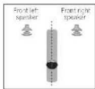
S.R AIR
Sound Retrever All!
Suitable for listening to the sound from a Bluetooth wireless technology device. The S.R AIR listening mode can only be selected when the ADAPTER input is
PHONES SURR
When listening through 'headphones, you can still get the effect of overall surround
Using Stream Direct


Use the Stream Direct modes when you want to near the infeas possible reproduction of a source. All unnecessary signal processing is bypassed.
AUTO
SURROUND
See Auto playback on page 29
DIRECT Sources are heard according to the settings made in the Manual SP Setup (speaker setting, channel level, speaker distance), as well as with dual mono settings. You will hear sources according to the number of channels in the signal. Phase Control, Acoustic Calibration EQ, Sound Delay, Auto Delay, LFE Attenuate and Center image functions are available.
PURE DIRECT Analog and PCV sources are heard without any digital processing.
Using the Sound Retriever
When audio data is removed during the compression process, sound quality often suffers from an uneven sound image. The Sound Retriever feature employs new DSP technology that helps bring CD quality sound back to compressed 2-channel audio by restoring sound pressure and smoothing jagged artifacts left over after compression.
Presspress S.RETRIEVER to switch the S.RTV (Sound Retriever) ON or OFF.
Note
- The Sound Retriever is only applicable to 2-channel sources.
Listening with Acoustic Calibration EQ
You can listen to sources using the Acoustic Calibration Equalization set in Automatically setting up for surround sound (MCACC) on page 20. Refer to these pages for more on Acoustic Calibration Equalization.
While listening to a source, press press EQ to switch the EQ (Acoustic Calibration EQ) ON or OFF. The MCACC indicator on the front panel lights when Acoustic Calibration EQ is active.
You can't use Acoustic Calibration Q with Stream Direct mode and it has no effect with headphones.
Listening to your system
Better sound using Phase Control
This receiver's Phase Control feature uses phase correction measures to make sure your sound source arrives at the listening position in phase, preventing unwanted distortion and/or coloring of the sound.
Phase Control technology provides coherent sound reproduction through the use of phase matching for an optimal sound image at your listening position. The default selling is on and we recommend leaving Phase Control switched on for all sound sources.
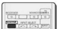
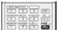
Press Reriewpress PHASE to switch the P.CTL (Phase Control) ON or OFF.
Note
- Phase matching is a very important factor in achieving proper sound reproduction. If two waveforms are in phase, they crest and trough together, resulting in increased amplitude, clarity and presence of the sound signal. If a crest of a wave meets a trough, then the sound will be out of phase and an unreliable sound image will be produced.
- If your subwoofer has a phase control switch, set it to the plus (+) sign (or 0°). However, the effect you can actually feel when Phase Control is set to ON on this receiver depends on the type of your subwoofer. Set your subwoofer to maximize the effect. It is also recommended you try changing the orientation or the place of your subwoofer.
-
Set the built-in lowpass filter switch of your subwoofer to OFF. If this cannot be done on your subwoofer, set the cutoff frequency to a higher value.
If the speaker distance is not properly set, you may not have a maximized Phase Control effect.
The Phase Control mode cannot be set to ON in the following cases: -
When the PURE DIRECT mode is switched on,
-
When the headphones are connected.
Using surround back channel processing
You can have the receiver automatically use 6.1 or 7.1 decoding for 6.1 encoded sources (for example, Dolby Digital EX or DTS-ES), or you can choose to always use 6.1 or 7.1 decoding (for example, with 5.1 encoded material). With 5.1 encoded sources, a surround back channel will be generated, but the material may sound better in the 5.1 format for which it was originally encoded (in which case, you can simply switch surround back channel processing off).
With a 7.1 channel surround system, audio signals that have undergone matrix decoding processing through surround back channel processing to which the Up Mix function is added are output from the surround back speakers.
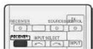
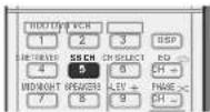
Press SB/press SB CH repeatedly to cycle the surround back channel options.
Each press cycles through the options as follows:
- SB ON - Matrix decoding processing for generating the surround back component from the surround component is turned on.
- SB AUTO - Matrix decoding processing for generating the surround back component from the surround component is switched automatically. Matrix decoding processing is only performed when surround back channel signals are detected in the input signals.
- SB OFF - Matrix decoding processing for generating the surround back component from the surround component is turned off.
Setting the Up Mix function
In a 7.1-channel surround system with surround speakers placed directly at the sides of the listening position, the surround sound of 5.1-channel sources is heard from the side. The Up Mix function mixes the sound of the surround speakers with the surround back speakers so that the surround sound is heard from diagonally to the rear as it should be.
Using the Up Mix function is effective when the speakers in the 7.1-channel surround system are set up as recommended in the example on page 10.
Depending on the positions of the speakers and the sound source, in some cases it may not be possible to achieve good results. In this case, set the setting to OFF.
1 Switch the receiver into standby.
2 While holding down PRESET ⇒ on the front panel, and hold the STANDBY/ONfor about two seconds.
UP MIX: OFF appears and the Up Mix function turns off. If you want to turn this function on, perform steps 1 and 2 again.
- When set to ON the (Up Mix) indicator on the front panel lights.
Note
- Set to ON regardless of this setting when playing DTS-HD signals.
- May automatically be set to OFF even when set to ON, depending on the input signal and listening mode.
Setting the Audio options
There are a number of additional sound settings you can make using the AUDIO PARAMETER menu. The defaults, if not stated, are listed in bold.

Important
Note that if a setting doesn't appear in the AUDIO PARAMETER menu, it is unavailable due to the current source, settings and status of the receiver.

1 PressPress AUDIOPARAMETER button.
2 Use / to select the setting you want to adjust.
Depending on the current status/mode of the receiver, certain options may not be able to be selected. Check the table below for notes on this.
3 Use to set it as necessary.
See the table below for the options available for each setting.
4 Press RETURN to confirm and exit the menu
Setting/What it does Option(s)
| EQ (Acoustic Calibration EQ)Switches on/off the effect of Acoustic Calibration EQ. | ONOFF |
| S.DELAY (Sound Delay)Some monitors have a slight delay when showing video, so the sound track will be slightly cut off sync with the picture. By adding a bit of delay, you can adjust the sound to match the presentation of the video. | 0.0 to 9.0(frames)1 second = 30frames (NTSC)Default: 0.0 |
Setting/What it does Option(s)
| MIDNIGHT/LOUDNESSaThe MIDNIGHT allows you to hear effective surround sound of movies at low volumes.The LOUDNESS is used to get good bass and trebe from music sources at low volumes. | |
| MIDNIGHT | |
| LOUDNESS | |
| S.RTV (Sound Retriever)bWhen audio data is removed during the WMA/MP3 compression process, sound quality often suffers from an uneven sound image. The Sound Retriever feature employs new DSP technology that helps bring CD quality sound back to compressed 2-channel audio by restoring sound pressure and smoothing jagged artifacts left over after compression. | |
| OFFd | |
| ON | |
| DUAL MONObSpecifies how dual mono encoded Dolby Digital soundtracks should be played. | |
| CH1 - Channel 1is heard only | |
| CH2 - Channel 2is heard only | |
| CH? CH2 - Both channels heard from front speakers | |
| F.PCM (Fixed PCM)This is useful if you find there is a slight delay before OFF recognizes the PCM signal on a CD, for instance.When ON is selected, noise may be output during playback of non-PCM sources. Please select another input signal if this is a problem. | |
| OFF | |
| ON | |
| DRC (Dynamic Range Control)Adjusts the level of dynamic range for movie soundtracks optimized for Dolby Digital, DTS, Dolby Digital Plus, Dolby TrueHD, DTS-HD and DTS-HD Master Audio (you may need to use this feature when listening to surround sound at low volumes). | |
| AUTOf | |
| MAX | |
| MID | |
| OFF | |
Setting/What it does Option(s)
| LFE ATT (LFE Attenuate) | 0 (0 dB) |
| Some Dolby Digital and DIS audio sources include ultra-low bass tones. Set the LFE attenuator as necessary to prevent the ultra-low bass tones from distorting the sound from the speakers. The LFE is not limited when set to 0 dB, which is the recommended value. When set to -15 dB, the LFE is limited by the respective degree. When OFF is selected, no sound is output from the LFE channel. | 5 (-5 dB) |
| 10 (-10 dB) | |
| 15 (-15 dB) | |
| 20 (-20 dB) | |
| ** (OFF) | |
| SACD G. (SACD Gain)g | 0 (0 dB) |
| Brings out detail in SACDs by maximizing the dynamic range (during digital processing). | -6 (+6 dB) |
| HDMI (HDMI Audio) | AMP |
| Specifies the routing of the HDMI audio signal out of this receiver (AMP) or through to a TV (THRU). When THRU is selected, no sound is output from this receiver. | THRU |
| A.DLY (Auto Delay)h | OFF |
| This feature automatically corrects the audi-c-to-video delay between components connected with an HDMI cable. The audio delay time is set depending on the operational status of the display connected with an HDMI cable. The video delay time is automatically adjusted according to the audio delay time. | ON |
| C.WIDTH (Center Width)i | 0 to 7 |
| (Applicable only when using a center speaker) | Default: 3 |
| Spreads the center channel between the front right and left speakers, making it sound wider (higher settings) or narrower (lower settings). | |
| DIMEN (Dimension)i | -3 to +3 |
| Adjusts the surround sound balance from front to back, making the sound more distant (minus settings), or more forward (positive settings). | Default: 0 |
Listening to your system
Setting/What it does Option(s)
| PNRM. (Panorama)1 Extends the front stereol image to include surround speakers for a 'wraparound' effect. | OFF |
| ON | |
| CIMG (Center Image)1 (Applicable only when using a center speaker) Adjust the center image to create a wider stereo effect with vocals. Adjust the effect from 0 (all center channel sent to front right and left speakers) to 10 (center channel sent to the center speaker only). | 0 to 10 Default: 3 (NEO-6 MUSIC) 10 (NFO-6) CINEMA) |
| H.GAIN (Height Gain) | L (Low) |
| Adjusts the output from the front height oscillator when listening in DOLBY PLLiz | M (Mid) |
| HEIGHT mode. If set to H, the sound from the top will be more emphasized. | H (High) |
a. You can change the MIDNIGHT/LOUDNESS options at any time by using MIDNIGHT button.
b. You can change the Scurd Retreiver feature at any time by using S.RETRIVER button.
c. WMA and MP3 playback available only via iPod USB input.
d. The default setting when the iPod USB or ADAPTER input is selected is ON.
e. This selling works only with dual mono encoded Dolby Digital and DTS soundtracks.
f. The initial set AUTO is only available for Dolby TrueHD's signals. Select MAX or MID for signals other than Dolby TrueHD.
g. You shouldn't have any problems using this with most SACD discs, but if the sound distorts, it is best to switch the gain setting back to 0 dB.
h. This feature is only available when the connected display supports the automatic audio/video synchronizing capability (lip-sync) for HDMI. If you find the automatically set delay time unsuitable, set A.DLY to OFF and adjust the delay time manually. For more details about the lip-sync feature of your display, contact the manufacturer directly.
i. Only available with 2 channel sources in DOLBY PLII MUSIC mode.
J. Only when listening to 2-channel sources in NEO:6 CINEMA and NEO:6 MUSIC mode.
Making an audio or a video recording
You can make an audio or a video recording from the built-in tuner, or from an audio or video source connected to the receiver (such as a CD player or TV).
Only video signals that were input to this receiver through a composite video cable or analog audio inputs can be recorded. Signals that were input through an HDMI cable, component video cable or digital audio cable (see Connecting other audio components on page 17 for more on connections).

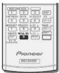
1 Press input function buttons to select the input function you want to record.
The input of the receiver will switch over, and you will be able to operate other components using the remote control.
The input source can also be selected by using INPUT
SELECT buters on the remote control, or by
using the front panel INPUT SELECTOR dial.
2 Select the audio input signal (if necessary).
Press RECEIVER'S SIGNAL SEL and select the analog inputs (A) for the source component of which you want to record (see page 22 for more on this).
3 Prepare the source you want to record.
Tune to the radio station, load the CD, video. DVD etc.
4 Prepare the recorder.
Insert a blank tape, MD. video etc. into the recording device and set the recording levels.
Refer to the instructions that came with the recorder if you are unsure how to do this. Most video recorders set the audio recording level automatically-check the component's instruction manual if you're unsure.
5 Start recording, then start playback of the source component.
Note
The receiver's volume, balance, tone (bass, treble, loudness), and surround effects have no effect on the recorded signal.
Some video sources are copy-protected. These cannot be recorded.
Chapter 6: The System Setup menu
Using the System Setup menu
The following section shows you how to make detailed settings to specify how you're using the receiver, and also explains how to fine-tune individual speaker system settings to your liking.

Important
The OSD will not appear if you have connected using the HDMI output to your TV. Use component or composite connections for system setup.
- If headphones are connected to the receiver, disconnect them.
- You can't use the System Setup menu when the iPod USB input is selected.

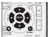
1 Switch on the receiver and your TV.
Press 品 RECEIVER to switch on.
2 Switch the TV input to the input that connects this receiver to the TV through the corresponding composite or component cable.
3 Press RBenRRess SETUP.
The System Selup menu appears on your TV. Use ↑/↓/←/→ and ENTER on the remote control to navigate through the screens and select menu items. Press RETURN to confirm and exit the current menu.
- Press SETUP at any time to exit the System Setup menu.
4 Select the setting you want to adjust.
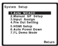
- Auto MCACC - This is a quick and effective automalic surround setup (see Automatically setting up for surround sound (MCACC) on page 20).
- Manual SP Setup
-
Speaker Setting - Specify the size and number of speakers you've connected (see below).
-
Crossover Network - Specify which frequencies will be sent to the subwoofer (page 35).
-
Channel Level - Adjust the overall balance of your speaker system (page 35).
-
Speaker Distance - Specify the distance of your speakers from the listening position (page 36).
-
Input Assign - Specify what you've connected to the component video inputs (see The input Assign menu on page 36).
-
Pre Out Setting - Specify how to use the PRE OUT SURR BACK/FRONT HEIGHT outputs (see The Pre Out Setting on page 37).
HDMI Setup - Sets synchronized operations when connected to a device/TV that supports the Control with HDMI function (see HDMI Setup on page 38).
-
Auto Power Down - Sets to automatically turn off the power when the receiver has not operated for several hours (see The Auto Power Down menu on page 37).
-
FL Demo Mode - Sets the demo display on the front panel display (see The FL Demo Mode menu on page 37).
Manual speaker setup
This receiver allows you to make detailed settings to optimize the surround sound performance. You only need to make these settings once (unless you change the placement of your current speaker system or add new speakers). These settings are designed to fine-tune your system, but if you're satisfied with the settings made in Automatically setting up for surround sound (MCACC) on page 20, it isn't necessary to make all of these settings.
CAUTION
- The test Iones used in the System Setup are output at high volume.
Q Important
Depending on the Pre Out Setting, there will be differences in the speaker items that can be adjusted. The OSD display for these operating instructions is an example of when the Pre Out Setting is set to Surr. Back.
Speaker Setting
Use this setting to specify your speaker configuration (size, number of speakers). It is a good idea to make sure that the settings made in Automatically setting up for surround sound (MCACC) on page 20 are correct.
1 Select 'Manual SP Setup' from the System Setup menu.
2 Select 'Speaker Setting' from the Manual SP Setup menu.
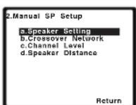
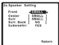
3 Choose the set of speakers that you want to set then select a speaker size.
Use ↔ to select the size (and number) of each of the following speakers:
The System Setup menu
- Front - Select LARGE if your front speakers reproduce bass frequencies effectively, or if you didn't connect a subwoofer. Select SMALL to send the bass frequencies to the subwoofer.
- Center - Select LARGE if your center speaker reproduces bass frequencies effectively, or select SMALL to send bass frequencies to the other speakers or subwoofer. If you didn't connect a center speaker, choose NO (the center channel is sent to the other speakers).
- Front Height - Select LARGE if your frontal height speakers reproduce bass frequencies effectively. Select SMALL to send bass frequencies to the other speakers or subwoofer. If you didn't connect front height speakers choose NO.
- You can only adjust the Front Height setting when Pre Out Setting is set to Height.
- Surr - Select LARGE if your surround speakers reproduce bass frequencies effectively. Select SMALL to send bass frequencies to the other speakers or subwoofer. If you didn't connect surround speakers choose NO (the sound of the surround channels is sent to the other speakers).
- Surr. Back - Select the number of surround back speakers you have (one, two or none). Select LARGE if your surround back speakers reproduce bass frequencies effectively. Select SMALL to send bass frequencies to the other speakers or subwoofer. If you didn't connect surround back speakers choose NO.
- You can only adjust the Surr. Back setting when Pre Out Setting is set to Surr. Back.
If you select one surround back speaker only, make sure that additional amplifier is hooked up to the PRE OUT L (Single) terminal. - Subwoofer - LFE signals and bass frequencies of channels set to SMALL are output from the subwoofer when YES is selected (see notes below). Choose Inc PLUS setting if you want the subwoofer to output bass sound continuously or you want deeper bass (the bass frequencies that would normally come out the front and center speakers are also routed to the subwoofer). If you did not connect a subwoofer choose NO (the bass frequencies are output from other speakers).
4 When you're finished, press RETURN.
You return to the Manual SP Setup menu.
Note
- If you select SMALL for the front speakers, the subwoofer will automatically be fixed to YES. Also, the center, surround, surround back and front height speakers can't be set to LARGE if the front speakers are set to SMALL. In this case, all bass frequencies are sent to the subwoofer.
- If the surround speakers are set to NO, the surround back speakers will automatically be set to NO.
- If you have a subwoofer and like lots of bass, it may seem logical to select LARGE for your front speakers and PLUS for the subwoofer. This may not, however, yield the best bass results. Depending on the speaker placement of your room you may actually experience a decrease in the amount of bass due to low frequency cancellations. In this case, try changing the position or direction of speakers. If you can't get good results, listen to the bass response with it set to PLUS and YES or the front speakers set to LARGE and SMALL alternatively and let your ears judge which sounds best. If you're having problems, the easiest option is to route all the bass sounds to the subwoofer by selecting SMALL for the front speakers.
Crossover Network
Default setting: 100Hz
This selling decides the cutoff between bass sounds playing back from the speakers selected as LARGE, or the subwoofer, and bass sounds playing back from those selected as SMALL. It also decides where the cutoff will be for bass sounds in the LFE channel.
- For more on selecting the speaker sizes, see Speaker Setting or page 34.
1 Select 'Manual SP Setup' from the System Setup menu.
2 Select 'Crossover Network' from the Manual SP Setup menu.
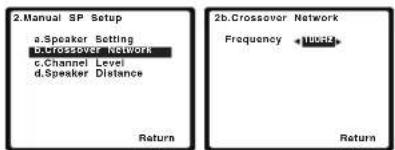
3 Choose the frequency cutoff point.
Frequencies below the cutoff point will be sent to the subwoofer (or LARGE speakers),
4 When you're finished, press RETURN.
You return to the Manual SP Setup menu.
Channel Level
Using the channel level settings, you can adjust the overall balance of your speaker system, an important factor when setting up a home theater system.
1 Select 'Manual SP Setup' from the System Setup menu.
2 Select 'Channel Level' from the Manual SP Setup menu
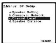
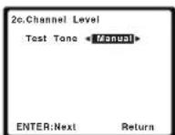
3 Select a setup option.
- Manual - Move the test tone manually from speaker to speaker and adjust individual channel levels.
- Auto - Adjust channel levels as the lost tone moves from speaker to speaker automatically.
4 Confirm your selected setup option.
The test lones will start after you press ENTER. After the volume increases to the reference level, test tones will be output.
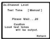
5 Adjust the level of each channel using / ⇒
If you selected Manual, use ↑/↓ to switch speakers. The Auto setup will outtostones in the order shown onscreen:
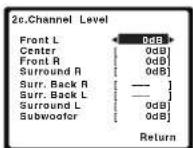
Adjust the level of each speaker as the test lone is emilled.
Note
If you are using a Sound Pressure Level (SPL) meter, take the readings from your main listening position and adjust the level of each speaker to 75 dB SPL (C-weighting/slow reading).
The subwoofer test lone is outal low volumes.You may need to adjust the level after testing with an actual soundtrack.
6 When you're finished, press RETURN.
You return to the Manual SP Setup menu.
Tip
- You can change the channel levels at any time by press RECEIVER. Then press CH SELECT and LEV +/- on the remote control. You can also press CH SELECT and use ↑/↓ to select the channel, and then use ←/→ to adjust the channel levels.
Speaker Distance
For good sound depth and separation from your system, you need to specify the distance of your speakers from the listening position. The receiver can then add the proper delay needed for effective surround sound.
1 Select 'Manual SP Setup' from the System Setup menu.
2 Select 'Speaker Distance' from the Manual SP Setup menu.
3 Adjust the distance of each speaker using ← / → .
You can adjust the distance of each speaker in 0.1 feet increments.
4 When you're finished, press RETURN.
You return to the Manual SP Setup menu.
The Input Assign menu
You only need to make settings in the Input Assign menu if you don't hook up your equipment according to the default settings for the component video inputs.
- Default settings:
- Component-1: DVD
Component-2: DVR (DVR/BDR)
Important
- If you connect any source component to the receiver using a component video input, you should also have your TV connected to this receiver's COMPONENTVIDEO MONITOR OUT output (down converting component video is not possible after assigning an input).
If you didn't make component video connections according to the defaults above, you must assign the numbered input to the component you've connected (or else you may see the video signal of a different component). For more on this, see Using the component video jacks on page 16.
1 Select 'Input Assign' from the System Setup menu.
2 Select 'Component Input' from the Input Assign menu.
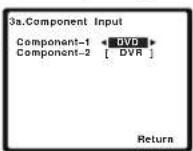
3 Select the number of the component video input to which you've connected your video component.
The numbers correspond with the numbers beside the inputs on the rear of the receiver;
4 Select the component that corresponds with the one you connected to that input.
Select between BD, DVD, TV (TV/SAT), DVR (DVR/BDR) or OFF
- Use ← / → and ENTER to do this.
- If you assign a component input to a certain function, any component inputs previously assigned to that function will automatically be switched off.
Make sure you have connected the audio from the component to the corresponding inputs on the rear of the receiver.
5 When you're finished, press RETURN.
You return to the Input Assign menu.
For the assignment of the digital signal inputs, see Selecting the audio input signal on page 22.
The System Setup menu
The Pre Out Setting
Specify either using the surround back speaker or the front height speaker connection with the PRE OUT SURR BACK/FRONT HEIGHT outputs. An additional amplifier is required for the speaker connection.
- Default setting: Surr. Back
1 Select 'Pre Out Setting' from the System Setup menu.
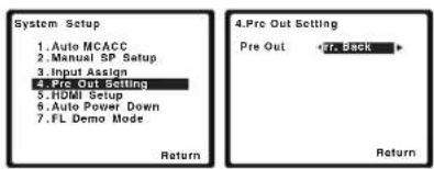
2 Select which speaker to connect to the PRE OUT SURB BACK/FRONT HEIGHT outputs using ↔ →
- Surr. Back - Connect the surround back speaker.
- Height - Connect the front height speaker
3 When you're finished, press RETURN.
You return to the System Setup menu.
The Auto Power Down menu
Set to automatically turn off the receiver after a specified time has passed (when the power has been on with no operation for several hours.
Default setting. OFF
1 Select 'Auto Power Down' from the System Setup menu.
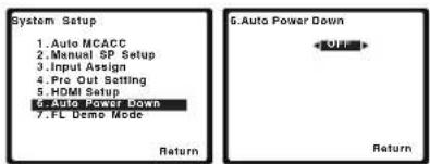
2 Specify the amount of time to allow before the power
is turned off (when there has been no operation).
- You can select 2, 4 or 6 hours, or OFF (if no automatic shuloff is desired).
3 When you're finished, press RETURN.
You return to the System Setup menu.
The FL Demo Mode menu
Sel whether or not various demo are to be shown on the front panel display.
1 Select 'FL Demo Mode' from the System Setup menu.

2 Choose ON or OFF for the demo display.
3 When you're finished, press RETURN.
You return to the System Setup menu.
Chapter 7: Control with HDMI function
Synchronized operations below with a Control with HDMI-compatible Pioneer TV or Blu-ray Dsc player or with a component of another make that supports the Control with HDMI functions are possible when the component is connected to the receiver using an HDMI cable.
Synchronized amp mode
The receiver's volume can be set and the sound can be muted using the TV's remote control.
Power synchronization with TV
Automatic switching of inputs
The receiver's input switches over automatically when the TV's input is changed or a Control with HDMI-compatible component is played.
Important
- With Pioneer devices, the Control with HDMI functions are referred to as "KURO LINK".
- You cannot use this function with components that do not support Control with HDMI.
We only guarantee this receiver will work with Pioneer made Control with HDMI-compatible components and components of other makes that support the Control with HDMI function. However, we do not guarantee that all synchronized operations will work with components of other makes that support the Control with HDMI function. - Use a High Speed HDMI® cable when you want to use the Control with HDMI function. The Control with HDMI function may not work properly if a different type of HDMI cable is used.
- For details about concrete operations, settings, etc., refer to also the operating instructions for each component.
Making Control with HDMI connections
You can use synchronized operation for a connected TV and up to four other components.
- Be sure to connect the TV's audio cable to the audio input of this unit. When the TV and receiver are connected by HDMI connections, if the TV supports the HDMI Audio Return Channel function, the sound of the TV is input to the receiver via the HDMI terminal, so there is no need to connect an audio cable. In this case, see ARC at HDMI Setup to ON (see HDMI Setup below).
For details, see Connecting using HDMI on page 14.
Important
- When connecting this system or changing connections, be sure to switch the power off and disconnect the power cord from the wall socket. After completing all connections, connect the power cords to the wall socket.
After this receiver is connected to an AC outlet, a 2 second to 10 second HDMI initialization process begins. You cannot carry out any operations during initialization. The HDMI indicator on the display unit blinks during initialization, and you can turn this receiver on once it has stopped blinking.
To get the most out of this function, we recommend that you connect your HDMI component not to a TV but rather directly to the HDMI terminal on this receiver. - While the receiver is equipped with four HDMI inputs, the Control with HDMI function can only be used with up to three DVD or Blu-ray Disc players or up to three DVD or Blu-ray Disc recorders.
HDMI Setup
You must adjust the settings of this receiver as well as the connected Control with HDMI-compatible components in order to make use of the Control with HDMI function. For more information see the operating instructions for each component.
1 Switch on the receiver and your TV.
Press 口 RECEIVERto switch on.
2 Switch the TV input to the input that connects this receiver to the TV through the corresponding composite or component cable.
3 Press RECEIVER
then
press
SETUP.
The System Setup menu appears on your TV. Use / / ← and ENTER on the remote control to navigate through the screens and select menu items. Press RETURN to confirm and exit the current menu.
- Press Setup at any time to exit the System Setup menu.
4 Select 'HDMI Setup' from the System Setup menu.
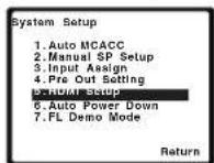
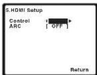
5 Select the 'Control' setting you want.
Choose whether to set this unit's Control with HDMI function ON or OFF. You will need to set it to ON to use the Control with HDMI function.
When using a component that does not support the Control with HDMI function, set this to OFF.
ON-Enables the Control with HDMI function. When this unit's power is turned off and you have a supported source begin playback while using the Control with HDMI function, the audio and video outputs from the HDMI connection are output from the TV.
- OFF - The Control with HDMI is disabled. Synchronized operations cannot be used. When this unit's power is turned off, audio and video of sources connected via HDMI are not output.
Control with HDMI function
6 Select the 'ARC' setting you want.
When a TV supporting the HDMI Audio Return Channel function is connected to the receiver, the sound of the TV can be input via the HDMI terminal.
- ON - The TV's sound is input via the HDMI terminal. This can only be selected when Control is set to ON.
- OFF - The TV's sound is input from the audio input terminals other than HDMI inputs.
7 When you're finished, press RETURN.
You return to the System Setup menu.
Before using synchronization
Once you have finished all connections and settings, you must:
1 Put all components into standby mode.
2 Turn the power on for all components, with the power for the TV being turned on last.
3 Choose the HDMI input to which the TV is connected to this receiver, and see if video output from connected components displays properly on the screen or not.
4 Check whether the components connected to all HDMI inputs are properly displayed.
About synchronized operations
The Control with HDMI-compatible component connected to the receiver operates in sync as described below.
Synchronized amp mode
From the menu screen of the Control with HDMI-compatible TV, set audio to be played through this receiver, and the receiver will switch to the synchronized amp mode.
- When in the synchronized amp mode, the synchronized amp mode is canceled when the receiver's power is turned off. To turn the synchronized amp mode back on, set audio to be played through the receiver from the TV's menu screen, etc. This receiver will power up and switch to the synchronized amp mode.
- When in the synchronized amp mode, the synchronized amp mode is canceled if an operation that produces sound from the TV is performed from the TV's menu screen, etc.
When the synchronized amp mode is canceled, the receiver's power turns off if you were viewing an HDMI input or a TV program on the TV.
Power synchronization with TV
- When the TV's power is set to standby, the receiver's power is also set to standby. (Only when the input for a component connected to the receiver by HDMI connection is selected or when watching the TV.)
Automatic switching of inputs
- The receiver's input switches automatically when the Control with HDMI-compatible component is played.
- The receiver's input switches automatically when the TV's input is switched.
The synchronized amp mode remains in effect even if the receiver's input is switched to a component other than one connected by HDMI.
About connections with a product of a different brand that supports the Control with HDMI function
The synchronized operations below can be used when the receiver's Control with HDMI function is connected to a TV of a brand other than Pioneer that supports the Control with HDMI function. (Depending on the TV, however, some of the Control with HDMI functions may not work.)
- When the TV's power is set to standby, the receiver's power is also set to standby. (Only when the input for a component connected to the receiver by HDMI connection is selected or when watching the TV)
The sound of TV programs or an external input connected to the TV can also be output from the speakers connected to the receiver. (If the TV does not support the HDMI Audio Return Channel function, this requires connection of an optical digital cable, etc., in addition to the HDMI cable.)
The synchronized operations below can be used when the receiver's Control with HDMI function is connected to a player or recorder of a brand other than Pioneer that supports the Control with HDMI function.
- When playback starts on the player or recorder, the receiver's input switches to the HDMI input to which that component is connected.
See the Pioneer website for the latest information on the models of non-Pioneer brands and products that support the Control with H DMI function.
Cautions on the Control with HDMI function
- Connect the TV and components (Bi-ray Disc player, etc.) directly to this receiver. Interrupting a direct connection with other amps or an AV converter (such as an HDMI switch) can cause operational errors.
- When the receiver's Control is turned ON, even if the receiver's power is in the standby mode, it is possible to output the audio and video signals from a player via HDMI to the TV without producing sound from the receiver, but only when a Control with HDMI-compatible component (Blu-ray Disc player, etc.) and compatible TV are connected. In this case, the receiver's power turns on and the power and HDMI indicators light.
Chapter 8: Controlling the rest of your system
Setting the remote to control other components
Most components can be assigned to one of the input function buttons using the component's manufacturer preset code stored in the remote.
However, please note that there are cases where only certain functions may be controllable after assigning the proper preset code, or the codes for the manufacturer in the remote control will not work for the model that you are using.
Note
TV CONTROL buttons are only dedicated to control the TV (for example, codes for TV, CATV, Satellite TV or DTV).
- You can cancel or exit any of the steps by pressing RECEIVER.
After one minute of inactivity, the remote automatically exits the operation.
Selecting preset codes directly
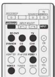
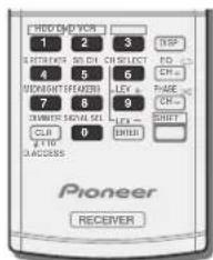
1 While pressing press and hold the 1' button for three seconds.
2 Press the input function button for the component you want to control.
The component can be assigned to the BD.DVD.TV,DVR/ BDR.CD.CD-R.VIDEO1 or VIDEO2 button.
- When assigning preset codes to TV CONTROL, press INPUT here.
3 Use the number buttons to enter the preset code.
You can find the preset codes on page 41. If the correct code has been input the power of the component being input will turn on or off. The power of the component being input will only turn on or off if that component is able to be turned on directly by remote control.
4 Repeat steps 2 through 3 to try a different code, or to enter a code for another component you want to control.
5 When you're done, press RECEIVER
Clearing all the remote control settings
You can clear all presets and restore the factory default settings.
While pressing RpsesBrid hold the 0' button
for three seconds.
Default preset codes
| Input function button | Preset code |
BD22a3
DVD 2256
TV0291
DVR/BDR2257
CD5000
CD-R5001
VIDEO16099
VIDEO2 1053
TV CONTROL 0291
Controlling the rest of your system
Controls for TVs
This remote control can control components after entering the proper codes or teaching the receiver the commands (see Controlling the rest of your system on page 40 for more on this). Use the input function buttons to select the component.
The TV CONTROL bullons on the remote control are dedicated to control the TV assigned to the TV CONTROL INPUT bullon.
| Button(s) Function | TV | DRV | Satellite/ Cable TV | |
| TV CONTROL | Switches the DV on or off. -√ - | |||
| Switches the TV or CATV between standby and on. | √ | √ | ||
| TV CONTROL INPUT | Switches the TV input. (Not possible with all models.) | √ | - | - |
| TV CONTROL CH +/- | Selects channels. √ √ √ | |||
| TV CONTROL VOL +/- | Adjust the TV volume. √ √ √ | |||
| ○ SOURCE | Press to switch the component assigned to the TV button on or off. | √ | √ | √ |
| DTV/TV Switches between the DV and analog TV input modes for Pioneer TVs. | √ | √ | - | |
| HOME MENU | Use as the GUIDE button for navigating. | √ | √ | √ |
| RETURN Use to select closed captioning with DV. | -√ | - | ||
| Number buttons | Use to select a specific TV channel. | √ | √ | √ |
| ENTER | Use to enter a channel. | √ | √ | √ |
| MENU | Press to display the DV menu. | - | √ | - |
| Select the menu screen. | √ | -√ | ||
| ↑/↓/←/→/ ENTER | Press to select or adjust and navigate items on the menu screen. | √ | √ | √ |
| CH +/- | Selects channels. | √ | √ | √ |
Controls for other components
This remote control can control these components (BD, DVR, CD, DVR (BDR), VCR, CD-R) after entering the proper codes or learning the receiver the commands (see Controlling the rest of your system on page 40 for more on this). Use the input function buttons to select the component.
| Button(s) | Function |
| For Blu-ray Disc player, DVD player, CD player, DVR (BDR), VCR, CD-R | |
| SOURCE | Press to switch the component between standby and on. |
| Press to return to the start of the current track. Repeated presses skip to the start of previous tracks. | |
| Press to advance to the start of the next track. Repeated presses skip to the start of following tracks. | |
| Pause playback or recording. | |
| Start playback. | |
| Hold down for fast forward playback. | |
| Hold down for fast reverse playback. | |
| Stops playback (on some models, pressing this when the disc is already stopped will cause the disc tray to open). | |
| Number buttons | Use to enter a title/character/track number. |
| DISP | Press to display information. |
| TOP MENU | Displays the disc 'top' menu of a BD/DVD player. |
| MENU | Displays menus for the current BD/DVD or DVR you are using. |
| ENTER/RETURN | Navigates BD/DVD menu/options. |
| HOME MENU | Displays the HOME MENU. |
| CH +/- | Selects channels. (DVR/VCR only) |
Button(s)
Function
For HDG/DVD/VCB recorder
HDD (SHIFT - 1) Swilcres to the hard cask controls.
DVD (SHIFT + 2) Switches to the DVD controls.
VCR (SHIFT + 3) Switches to the VCR controls.

Preset Code List
You should have no problem controlling a component if you find the manufacturer in this list, but please note that there are cases where codes for the manufacturer in the list will not work for the model that you are using. There are also cases where only certain functions may be controllable after assigning the proper preset code.

Important
We do not guarantee the operations of all the manufacturers and devices listed. Operation may not be possible even if a preset code is entered.
| example: | |
| TV | Category |
| Pioneer 0291 | Preset code |
| Manufacturer | |
Controlling the rest of your system
TV
Pioneer 0291-013,0294.0286 Adm 0001-014
Adventura 2012
Aiwa 000
Akai 0002,0100
Albatron CC Alleron CC
America Action C104
Amtron CCC
Anam 0104 120
Anam National 009-0085 126 0001,0005,0006,0020
AOC 0004,0103,5008,5168
Apex 0001,0102,0106
ApexoX, 10
Aventura 0013
Axion 0094
Bang & Olufsen0111
Belcor
Bell & Howell 001
Benq Bradt
Brardford 606-604
Brillian 079
Brickwood 2004
Brokson 0102
Candle 0004,0006,0012,0100
Carnivale 9100
Carver 6101
CCE 00 Calibarity
Celebrity 10:00
Changhong:106
Citizen 0004,0005,0008,010C
Clarion 010
Coby
Colortyme 0004,0006 Concorct 00040006
Conterto 604,605
Contero104
Durabrand0041,0103.0104
Dwin0014
Electroband 002
Electrograph 107
Electrohome 0002,0003,0004
0006 1.0000
Element 99266066637
Emerson 0002,0006,0007
0006:0008:0023:03,0164
Emprex 0052 Envision 2004
Epon 00E1
ESA
Fuiitsu 0009
Funai CC06,0009,0103,0104
Futuretech 0008,0104
Gateway0067,0107,0108
GE0006,0002.0004,0006,0010
0016.039274 0007.039
GFM C8C.004 Ciblral 2226, CC11, CC003
Gibrater004-6011-0099 0103
000Goldstar2004-0005-0006
Goldstar 900P,800S,600E 0067010C
Gridente 0356
Grunpy 0008,0009,0104
HaierC112
Hallmark0004 C008
Harman/Kardon 0101
Harvard 0008 C104
Herman 0003
Havermy 0012 Havermy Packard 0053
Hewlett Packard License 16/69
Hisense 000 Hitachi004-0006-0007
Hyundai0098
10009
IMAAUSS
Infinity 9191
InFocus 0074
Initial0091
Insignia 0085.0086
Integ. 009
Janei 2
JBLC101 10Dowse 232222429%
JC Penney 0533,534,536392005-0010
000C:0ICB 0009
Jensen004 0006
IVC 2997.0016.C44
Kawasho 0002,0004,0006
KEC0104
Kenwood 0004,0006,0100 Radio Shack 0100,0104
KLH0106
KlossNovabeam 0008,0012
Taung 003,516
Tao 2010,212
Technics 2010/358
Techuned 2001/60
Tecnwo 00040006010 Tekpika 00010001002b
Teknika 0051,0394,3883 0006.0007.0008.0009.C101
0104
TMK 0004,0006
TNCI 0099
Toshiba 0025,0028,0036
0068,0040,0043,0102
Vector Research 0100
Vidikron 0101
Vidtech004,005,000
Viewsonic 0058, 0107
Viking 2
Viore 2089
Vizio 5602,0070,0071,C1C
Wards 0000,0001,2004,0005
0006,0009,0130,0101
Waycon0102
Westinghouse 0047,0051
White Westinghouse 002
Yamaha 0004,0005,0006,0100
Zenith 0001,0004,0011,0015
0099
一
BVD
If operations are not
possible using the preset
codes below, you may be
able to conduct operations
with the preset codes for
theBD.DVR(BDR, HDR)
Pioner 2015-2014
PIF1 Acc
Accurun 202
Advent 20
Alwa 20
Akai 2006
A1-0070
Alco 2075
Allegra 2067
Alegro 2001
Amphion Me
AMW2357
Apex 2002, 2018, 2079, 2080
Apple 2058
Arrgo2088
Aspire 2013
Ast
Audiovox 207C
Axion2045
Bang & Olufsen 2081
Blaupunkt208C
Blue Parade
Boston
Broksonic 2066
California Audio Labs, 268
CambridgeSoundWorks COE
2006 Cine Vision1987
Cinevision 2007
Coby 2009
Coby 2019
Gurt Met
Curtis Mathies 2009 CyberHome 2000,2688
Cyber Home Cyttron 158
Daewoo2021, 2023
Denon 22
Desay2055
DiamondVision 2042
Disney202
Duroabran
Emerson 2067, 2082, 2091
Entero
ESA263.2017
Fisher 283
Funai201
FANALGE 2018
GEM243
Go Video:
Gradient
Greenhill 2080
Hager 2004
Harman/Kardon 2030, 2064
Hitachi20
Hiteker 2079
Live 2062
102038
Initial 2035, 2050
Insignia 2036,2064,2091
Integra 2078
Symphony 260
JBL2084A
MC25 10070
Kawasaki 270
If
Kenwood 2028, 2068
KLH 200
Koss 2024,2039,2015
Landel 2015
Lasonic289
Lenoxx 2074.2096
LG2019,2051,2061,2082,2087
Liquid Video 2013
Liteon 2023,2032 12267-5976-6864
Magnavox 2057, 206, 2091
Magnetov 2056
Memorex 2000 Min 3977
Microsoft 2017
Mintok 2005, 9
Mitsubishi2020
mitsubishi Nesa 28
Next B
Next Base 203 Nexttech 21b6
Onky 2017
Onkyo 2016 Onp741
Oppo 2061,2067 Critera 2069,507
Onrion2008,2070
Baparanic2005,2007,2014
Panasonic 000,2007.2017;
2052,2053,2006,2008,2010
Philips 2045, 2075
Proceeds 2078
Proces 975
Ploscan 2079
Owester 2060
Qwestal 2008 PCA 2008,2016,2017,2017
2078.2080
Recent 2074
Rin 205
Ri0 602
SOMC2009,2011,2015
Samsung 2008, 2011, 2012 2013, 2014, 2015
Sansui 20
Sanal 2066,2083
Shany 2035
Sherwood 2083
Shinsonic2086
Sonic Blue 2087
Sony2009, 2004, 2010, 2012
2027204620472048
Sungale 2054
Superscan 208
Sylvania 2023, 2067, 2091
Symphonic 2923
Teac 2010
Technics 2068
Theta Digital 2073
Toshiba 2001, 2006, 2019
20662076
Trutech2000
Urban Concepts 2076
US Logic 2086
Venturer207C
Xbox 2017
Yamaha 2005, 2068
Zenith 2019, 2076, 2082, 2087
BD
If operations are not
possible using the preset
codes below; you may be
able to conduct operations
with the preset code
the DVD.DVR (BDR)
HDR).
Pioneer 2255,2192,228
Denon2310,2311,2312
Hitachi 2307, 2306, 2309
JVC2290,2291,2293,2294
2296,2296
LG 2286,2287
Marantchi 0000
Mitsubishi 2000,253
Ongyko 9989
Panasonic2212282263
Panishe2211,2216,2278, 2290
Samsung22
Sharp230423052306
Sun 2089,2084,2285,2202
Sony 2288.2262
Toshiba 2288.2262
Yamaha 2297,2298 2299
DVR (BDR, HDR)
If operations are not
possible using the preset
codes below, you may be
able to conduct operations
with the preset codes for
the DVD.BD
Pioneer2257,2193,2258,2259
2280,2261,2264,2265,2266
2270
Panasonic2263,2269
Sharp 2267, 2275
Sony 2268, 2971, 2972, 2273
2276
Toshiba2274
VCR
Pioneer 1053,1108
ABS 1017
Adventura 1005
Aiwa 1005
Alienware10-7
American High 1004
Asha 1002
Audio Dynamics 1000
Audiovox 003
Bang & Olufsen 1032
Beaumark1902
Controlling the rest of your system
Bell & Howell 1001
Calix 1003
Candle 1002,1003 1874
Canon 1004
Citizen 1002, 1003
CoIyTeM 100C
Craig 502,1003
Curtis Mathes 1000,1002
1004
Cybernex 1002
CyberPower 1917
Sydney
DBX
Dell
DIRECTV 1016,1020,1022
1023,1024,1027,1030,1031
Dish Network 029
Dishpro 1029
Durabrand 1018
Dynatech 1005
Echostar
Electrohome 1003
Electrophonic 003
Emerson 1003, 1004, 1005
Expressvu
Fisher 100
Fuji 012
Funai 1005
Garrard 1008
Gateway 107
GE 1002
GOI 1029
Goldstar 1000,1003
Gradient 100s
Harley Davidson 1005
Harman/Kardon
Headquarter 001
Hewlett Packard 1017
HNS 016
Howard Computers 1018
HP 1017
HTS 1029
Hughes Network Systems 10
1018,1020,1022,1023,1024 1026,1027
Humax [1]
Hush 197
JUPPOWED 1917
BOYPOWER 1017
Instant Replay 1004
JC Penney 1000,1001,502 1003-1004
104
VCG1000160116001029
JVC 1000,1001,1020,1029 Konwocd 1000,1001
Kenwood 1992
Kodak 1003,504
LC-1802
LG 100
Linksys 107
Haveta 1296
Lloyd's LXX1002
Ex 1005 Moerney 1964.1918
Magnavox 1004,1918
Magnin 105
Marantz 1000,10017004
Marta 1003
Media Center PC 1017
MEI
Memorex 1001,1002,1003.
1004.1006,1018,1019
MGN Technology 1002
Microsoft
Mind 1917
Mitsubishi 1010
Motorola 1004
MTC 1902
Multitech 1002.1005
NEC10001001
Nikko 1993
Niveus Media 1017
Noblex 1002
Northgate 1917
Olympus 1004
Olympus 1003
Orion 1014,1213
Panasonic 1004 1003
Pahleco 104
Philips 1004 1011 1916 1020
1022.1025.1024.1025
Philips Magnavox 101
Philips Me
Pilot 1993
Pilot 1003
Brocar, 105
Proscan 1004
Dulac 1268
Pusar 158
Querter 100
Quarter 100
Quota 100
Quartz 1001
Quasar 1004
Radio Shack 1003 Radio Shack (P.O. Box 1201)
Radio Shack/Realistic 135, 1400-1600-1624-6995
1002,1003,1004,1005
Radix 1005
Randex 1003
RCA 1002100410071018
10201022
Realistic 100,002,160
1004.1005
ReplayTV 1026
Ricavision 1017
Runco 1018
Samsung 1002, 1016, 1022
1024
Sanky 1018
Sansui 1014, 1019
Sanyo 1001, 1002
Sears 1001, 1003, 1004
Sharp 1012
Shogun 1002
Singer1004
Sonic Blue 1026
Sony 1996,1999,1917,1921
Stack 1017
STS 1004
Sylvania 1004, 1005
Symphonic 1005
Systemax 1017
Tangar Systems 1017
Tandy Systems 1997 Tandy 2003
Tashiko 1003
Teac 1005
Technics 1004
Tekpika1003,1004,1005
Tivo 1016,1020,1021,1022
1025
TMK 102
Toshiba 1015, 1017, 1028
Totevision 1002.1003
Touch
UltimateTV 05
Unitech 1002
Vector Research 100C
Video Concepts 1000
Videosonic 1002
Viewsonic 13
Voodoo
Wards 1002,1003,1004,1995
XR-1000 1204.1005
Yamaha 1000,1001
Yannane 103-1018
ZT Group 2017
21 G
Satellit
Pioneer 6097,6098
ADB60256001
Akai Liang
Alba6005.5011.5013
Allsat 6102
Alltech611
Amstrad6033,6030,6044
Anton6013
Acatlon
Austar 600CC6045
Roll ExpressVul
Ben Express TV British Sky Broadcasting
6030
Canal6105
Chaparral 5034
CN5003
Cockat 6021
Crossdigital
Cipan 84
Bige 594
Bigg 6052
DigiWave 6070.6119.6:11.6062
Direct 666,670,670,670,682 683,6117,6293,6298,6295
6063.6113.6098.5358.6054 6068.6069.6259.6243.6018
609.6000,6039,5943,6018 6114.6115.6116.6202
B114.6115,6116,5993
Bihn Netbnt 50072
Dish Network System 0022, 6988-6977-0021
6089.6033.6044
Disnpro 6002689,6945etco-60026896003
Echostar 6002, BUB95, ECU36 8885-6887-6884
8008.6003.6004
Expressvu 5002,6004
Fortec Star
Fresat 114
FunaiBUN
GE 6111
General Instrument 6032
GOI602,604
Grundig 5007,6030
Hirschmann 6033
Hisense 6020
Hitachi 5038,6049
Houston 8002
HTS6002.6004
Hughes Network Systems
5113.6038.605461146115
6116
Hyundai 2019
ybjieshou@20.com
Innova 5053
Inova 6932 Jerrold 6032
JVC 602,6003,6004
Kathrein 6096
Lava 6053
169478
Marantz 502
McIntosh 6132
MitsubishiFOS
Motorola 632.6052
NEC650
Netsat 8059
Next Level 6/52
Next Level 500
Nakai 8025666661188119
Nokia 0020,0020,0110,0119 8121
0627 60356035
Pace 6038:6065, 1000000000000
Panarex 6000
Panoe 6000
Panaonco 000s Pnss
Pansat 6016,6022
DL 899369999999
Philips 5,042,6113,6038,6084 6053,6053,6100,6107,6200
6083.6089.6107.6103.6297 6084
014 Primostor 6032
Pnneae 6109611
Proscan 0110,0111 Proton 6000
Pd010520 RadioStock 6003,6111,6032
Radish 8056
Rae 8000611081118112
RCA6002.0110.011188109,6961,6114
6014
Saba 6017
Scam 8946-8999
Tivo6113,6114,6115,6116
Toshiba 6038,6054,6039
TPS 6041
Triasat 6033
Ultrasat 602
US Digital 602C
USDTV5323
ViewSat6048
Voom 5032
Zehnder610
Zenith 6042, 6069, 6037
Satellite Set Top Box
(SAT/PVR)
Combination)
Bell ExpressVu 6002,6003
DircTV 60708:10.80
8080.699.614.61
Dish Network System
605
Dishpro 60026089
Echostar 6002,6089,6003
Expressvu 6002
Hughes Networ
6113.6174.6115.61
JVC 6003
Motorola 6032
Philips 613,614
Proscan 6110
Samsung €114
Sonicview 6055,6107
Sony 052
Star Choice 6032
Tyo 6113.6114.6115.6116
Bright House 50746029
Cable One 6074,6229
Cablevision60746029 电话:(010)85333333
Charter 6074, 5029, 6058
Cisco 8029,8028,6
Comcast 6014,6029,1982
Cox6074 6029
Digeo 5029, 8058
Direct
Emerson 6122
Fosgate6072
General Instrument 6073
6072.6122
Homecast 6024
i3 Micro607
Insight 6074.6073.6029
Jebsee 8122
1 + u/8 = u/8 + 12
Jerrold 6073,6072,6122
Knology 6029
Macab 6040
Mediacom 6074,6029
Memorex 61
Motorola 6074,6073,6072
60/29.5:22
MTS 6094
Myrio 6077, 6078
Noos 6040
Pace 6074.6029,6028,6106
663
Panasonic 6112 6083
Paragon 6112
Penney 6112
Philips 6012
Pulsar 6112
Quas
Regal 607
Rogers 6029
Runco 6112
Samsung 6095
Scientific Atlanta 6029, 5028
6027.51
Sejin 6077
Shaw 8974
Starcom 6122
Stargate 6122
Suddenlink 6074,6029
Supercable 6072
Time Warner 601
Time:51/6
Toshiba E112
United Cable 3072,6122
US Electronics 54
Videoway 6112
Zenith
1
Cable Sci.
Cable Set Top
(Cable/PVR)
Combination)
Pioneer6029
Amina 6978
Bright House 50746029
Cable One 607&608
Cablevision 607
Cableview002363003003003003003003003003003003003003003003003003003003003003003003003003003003003003003003003
Cisco 602150
Comcast 674.50295083
6176
Cox
C0X 6017P
Bigoe Homestead
Homecast 6024 Insight 6074 609
Inlogy 6028
Kthology 225 Mediarom 60
Mediacn 6072,6082
Motorola
MYI0697
Pace 0029
Panasonic 6083
Rogers 6029
Scientific Atlanta 6029
Shaw 6074
Suddenlink 8074
Supercable 6072
Time Warner 6074,6029,6058
Tiyio 6078
CD
Pioneer 5006-5013
PIONEER 0AKAI5043
Asuka
Denon 5019
Fischer 5046
Fisher 90 Goldstar
Goldstar 8649 Hitachi 5042
Kenywood
Kelwood 9020,9021,9031 Luxman 5049
Luxman 5043 Marantz 5033
0000000000000000000000000000000000000000000000
Silkyo 691-100 Panasonipr 6226
Philips 5022,5032,5044
BCA 5013-5029
RCA 5052
Roadstar
sharp 6001 Scrib5012,5023,5026,5027
sory 5082,507
TEAC6015,5016,5034,5035.
503
Technics 5021
Victor 5014
Yamaha 5024,5025,5038
504508
CD-R
Pioneer 5001,5053
Philips 1054
Yamaha 5055
Tuner
Pioneer 5060
Laser Disc Player
Pioneer 5002.50
- 实验原理
Casette Deck
Pioneer 5058,5069
Digit
Pioneer 5057
MD
Pioneer 5056
Chapter 9: Additional information
Troubleshooting
Incorrect operations are often mistaken for trouble and malfunctions. If you think that there is something wrong with this component, check the points below. Take a look at the other components and electrical appliances being used because sometimes the problem may lie there. If the trouble isn't sorted out even after going through the checks below, ask your nearest Pioneer authorized independent service company to carry out repair work.
If the unit does not operate normally due to external effects such as static electricity disconnect the power plug from the outlet and insert again to return to normal operating conditions.
General
The power does not turn on.
→ Disconnect the power plug from the outlet, and insert again. → Make sure there are no loose strands of speaker wire touching the rear panel. This could cause the receiver to shut off automatically.
The receiver suddenly switches off.
When the Auto Power Down function is working, the power will automatically turn off if the receiver has not operated for several hours. Check the setting for the Auto Power Down function (see The Auto Power Down menu on page 37).
After about a minute (you won't be able to switch the unit on during this time), switch the receiver back on. If the message persists, call a Pioneer authorized independent service company.
The power suddenly turns on or off, or the input suddenly changes (When the Control with HDMI is ON).
This happens because of the synchronized operation due to the Control with HDMI function. If synchronized operations are not needed, set the Control with HDMI to OFF (see HOMI Setup on page 38).
OVERHEAT shows in the display and the power turns off. → The temperature within the unit has exceeded the allowable value. Try moving the unit for better ventilation (see page 2) → Lower the volume level. TEMP shows in the display and the volume level drops.
The temperature within the unit has exceeded the allowable value. Try moving the unit for better ventilation (see page 2).
Lower the volume level.
No sound is output when an input function is selected. → Use MASTER VOLUME to turn up the volume.
→ Press MUTE on the remote control to turn mating off.
→ Press SPEAKERS to select the proper speaker set (see Switching the speaker system on page 12).
→ Sel the SIGNAL SEL to H (HDMI). C1/O1/O2 (digital) or A (analog) according to the type of connections made (refer to page 22).
→ Make sure the component is connected correctly (refer to Connecting your equipment on page 10).
Check the audie output settings of the source component.
Refer to the instruction manual supplied with the source component.
No image is output when an input function is selected.
→ Make sure the component is connected correctly (refer to Connecting your equipment on page 10).
- Use the same type of video cables for the source component and TV to connect to this receiver (see About video outputs connection on page 13).
Check The Input Assign menu on page 36 to make sure you're assigned the correct input.
The video input selected on the TV monitor is incorrect. Refer to the instruction manual supplied with the TV.
No sound from subwoofer.
Make sure the subwoofer is switched on.
→ If the subwoofer has a volume knob, make sure it's turned up.
The Doble Digital or DTs source you are listening to may not have an LFE channel.
→ Switch the subwoofer setting in Speaker Setting on page 34 to YES or PLUS.
Switch the LFE ATT (LFE Attenuate) on page 32 to LFEATT0 or LFEATT5
No sound from surround or center speakers.
→ Connect the speakers properly (refer to page 11).
→ Refer to Speaker Settings on page 34 to check the speaker settings.
Refer to Channel Level on page 35 to check the speaker levels.
The Phase Control feature doesn't seem to have an audible effect.
If applicable, check that the lowpass filter switch on your subwoofer is off, or the owpass cutoff is set to the highest frequency setting. If there is a PHASE setting on your subwoofer, set it to 0° for depending on the subwoofer, the setting where you think it has the best overall effect on the sound).
Make sure the speaker distance setting is correct for all speakers (see Speaker Distance on page 36).
Considerable noise in radio broadcasts.
Connect the antenna (page 18) and adjust the position for best reception.
- Route any loose cables away from the antenna terminals and wires.
→ Fully extend the FM wire antenna, position for best reception, and secure to a wall (or connect an outdoor FM antenna).
Connect an additional internal or external AM antenna (page 18).
Turn off equipment causing interference or move it away from the receiver (or move antennas farther away from equipment causing noise).
Broadcast stations cannot be selected automatically.
→ Connect an outdoor antenna (refer to page '8). Noise during playback of a cassette deck.
Move the cassette neck away from your receiver until the noise disappears.
No sound is output or a noise is output when software with DTS is played back.
Make sure the player's settings are correct and/or the OTS signal output is on. Refer to the instruction manual supplied with the DVD player.
There seems to be a time lag between the speakers and the output of the subwoofer.
See Automatically selling up for surround sound (MCACC) on page 20 to set up your system again using MCACC (this will automatically compensate for a delay in the subwoofer output).
After using the Auto MCACC setup, the speaker size setting (LARGE or SMALL) is incorrect.
Low-frequency noise could have been caused by an air conditioner or motor. Switch off all appliances in the room and run the Auto MCACC setup:
Additional information
Can't operate the remote control.
→ Replace the batteries (refer to page 9).
Operate within 7m (23 ft), 30° of the remote sensor (refer to page 9).
→ Remove the obstacle or operate from another position,
Avoid exposing the remote sensor on the front panel to direct light.
The display is dark or off.
Press DIMMER on the remote control repeatedly to return to the default.
The front panel display switches over for no apparent reason to various different displays.
This happens because the demo display is in operation, to turn off the demo display, press any button to go back to the original display, or set the FL Demo Mode to OFF (see The FL Demo Mode menu on page 37).
The receiver doesn't recognize iPod touch/iPhone.
Try the following.
1. Simultaneously keep pressing the sleep button and home button on the iPad touch or iPhone for over 10 seconds to resign.
2. Turn on the receiver.
3. Connect the iPod touch/iPhone to the receiver
The Bluetooth wireless technology device cannot be connected or operated. Sound from the Bluetooth wireless technology device is not emitted or the sound is interrupted.
- Check that no object that emits electromagnetic waves in the 2.4 GHz band (microwave oven, wireless LAN device or Bluetooth wireless technology apparatus) is near the unit. If such an object is near the unit, sell the unit far from it. Or, stop using the object emitting the electromagnetic waves.
Check that the Bluetooth wireless technology device is not too far from the unit and that obstructions are not set between the Bluetooth wireless technology device and the unit. Set the Bluetooth wireless technology device and the unit so that the distance between them is less than about 10 m (32 ft) and no obstructions exist between them. -
Check that the Bluetooth ADAPTER and the ADAPTER PORT terminal of the unit are correctly connected.
The Bluetooth wireless technology device may not be set to the communication mode supporting the Bluetooth wireless technology. Check the setting of the Bluetooth wireless technology device. -
Check that pairing is correct. The pairing setting was copied from this unit or the Bluetooth wireless technology device. Reset the pairing.
- Check that the profile is correct. Use a Bluetooth wireless technology device that supports A2DP profile and AVRCP profile.
HDMI
No picture or sound.
If the problem still persists when connecting your HDM component directly to your monitor, please consult the component or monitor manual or contact the manufacturer for support.
No picture.
Video signals that are input from the analog video terminal will not output from the HDMI terminal. Signals that are input from the HDMI terminal will not output from the analog video terminal. Be consistent with the type of cable between input and output.
→ Depending in the output settings of the source component, it may be outputting a video forma that can't be displayed. Change the output settings of the source, or connect using the component or composite jacks.
→ This receiver is HDCP compatible. Check that the components you are connecting are also HDCP-compatible. If they are not, please connect them using the component or composite video racks.
→ Depending on the connected source component, it's possible that it will not work with this receiver (even if it is HDCP-compatible), in this case, connect using the component or composite video jacks between source and receiver.
→ if video images do not appear on your TV, try adjusting the resolution, Deep Color or other setting for your component.
→ output signals in Deep Color, use an HDMI cable (High Speed HDMI Cable) to connect this receiver to a component or TV with the Deep Color feature.
The OSD screen (System Setup menu or the menu screen for the iPod/USB) isn't displayed.
The OSU will not appear if you have connected using the HDMI output to your TV. Use component or composite connections when setting up the system.
No sound, or sound suddenly ceases.
- Check that the Audio Parameter setting is set to HDMI AMP/THRU (refer to page 32).
If the component is a DVI device, use a separate connection for the audio.
→ HDMI format digital audio transmissions require a longer time to be recognized. Due to this, interruption in the audio may occur when switching between audio formats or beginning playback.
→ Turning on/off the device connected to this unit's HDMI/OUT terminal during playback, or disconnecting/connecting the HDMI cable during playback, may cause noise or interrupted audio.
Synchronized operation not possible using Control with HDMI function.
Check the IDMI connections.
The cable may be damaged.
→ Select ON for the Control with HDMI setting (see HDMI Setup on page 38).
Turn the TV's power on before turning on this receiver's power.
Set the TV side Control with HDMI setting to on (see TV's operating instructions).
Important information regarding the HDMI
connection
There are cases where you may not be able to route HDMI signals through this receiver (this depends on the HDMI equipped component you are connecting-check with the manufacturer for HDMI compatibility information). If you aren't receiving HDMI signals properly through this receiver (from your component), please try the following configuration when connecting up.
Configuration
Connect your HDMI-equipped component directly to the display using an HDMI cable. Then use the most convenient connection (digital is recommended) for sending audio to the receiver. See the operating instructions for more on audio connections. Set the display volume to minimum when using this configuration.
Note
Depending on the component, audio output may be limited to the number of channels available from the connected display unit (for example audio output is reduced to 2 channels for a monitor with stereo audio limitations).
If you want to switch the input source, you'll have to switch functions on both the receiver and your display unit.
- Since the sound is muted on the display when using the HDMI connection, you must adjust the volume on the display every time you switch input sources.
iPod messages
'iPod/USB Error 1 (I/U ERR1)
iPod/USB Error 3 (I/U ERR3)
→ Switch off the receiver and reconnect the iPod to the receiver. If this doesn't seem to work, try resetting your iPod.
iPod/USB Error 2 (I/U ERR2)
→ Switch off the receiver and reconnect the iPod to the receiver. If this doesn't seem to work, try resetting your iPod.
→ An iPod not supported by this receiver is connected. Connect the iPod supported by this receiver (see page 23).
'No Track'
When there are no tracks in the category selected on the iPod. Select a different category.
USB messages
'Pod/USB Error 1 (I/U ERR1)'
There is a problem with the signal path from the USB to the receiver. Switch off the receiver and reconnect the USB to the receiver.
iPod/USB Error 3 (I/U ERR3)
When there is no response from the USB, Swi1con off the receiver and reconnect the USB to the receiver.
iPod/USB Error 4 (I/U ERR4)
The power requirements of the USB device are too high for this receiver. Switch off the receiver and reconnect the USB to the receiver.
SIRIUS radio messages
'NO ANT'
- Antenna is not properly connected. Check that the antenna cable is attached securely.
CHECK SIRIUS TUNER
SIRIUS Connect timer is not properly connected. Check that the B pin mini DIN cable and AC Adapter are attached securely.
'NO SIG'
- The SiRUS signal is too weak at the current location. There is no SiRUS signal or the SiusConnect Tuner is connected.
'SUB UPDT'
Unit is updating subscription. Wait until the encryption code has been updated.
UPD ***%
→ Unit is updating channels. Wait until the encryption code has been updated.
"INVLD CH"
- Selected channel is not available/does not exist. Select another channel.
About iPod/iPhone/iPad
Made for


"Made for iPod," "Made for iPhone" and "Made for iPad" mean that an electronic accessory has been designed to connect specifically to iPod, iPhone, or iPad, respectively, and has been certified by the developer to meet Apple performance standards. Apple is not responsible for the operation of this device or its compliance with safety and regulatory standards. Please note that the use of this accessory with iPod, iPhone, or iPad may affect wireless performance.
iPod and iPhone are trademarks of Apple Inc., registered in the U.S. and other countries. iPad is a trademark of Apple Inc.
Resetting the main unit
Use this procedure to reset all the receiver's settings to the factory default. Use the front panel controls to do this.
1 Switch the receiver into standby.
2 While holding down BAND, press and hold
STANDBY/ONfor about two seconds.
3 When you see RESET? appear in the display, press AUTO SURROUND/STREAM DIRECT.
OK? shows in the display.
4 Press ALC/STANDARD SURR to confirm.
OK appears in the display to indicate that the receiver has been reset to the factory default settings.
Cleaning the unit
- Use a polishing cloth or dry cloth to wipe off dust and dirt.
- When the surface is dirty, wipe with a soft cloth dipped in some neutral cleanser diluted five or six times with water, and wrung out well, and then wipe again with a dry cloth. Do not use furniture wax or cleansers.
- Never use hrimners, benzene, insecticide sprays or other chemicals on or near this unit, since these will corrode the surface.
Additional information
Specifications
Amplifier section
Continuous average power output of 80 watts* per channel, min., at 8 ohms, from 20 Hz to 20 000 Hz with no more than 0.08% ** total harmonic distortion
no more than 0.08% total harmonic distortion. Front (stereo) . 80 W + 80 W Power output (1 KHz, 8Ω, 0.05 %) . 110 W per channel
Guaranteed speaker impedance
FRONT:A.B. 6Ω to 16Ω
FRONTA+B 12Ωto16Ω
SUBROUND,CENTER 6Ω to 16Ω
- Measured pursuant to the Federal Trade Commission's Trade
Regulation rule on Power Output Claims for Amplifiers
** Measured by Audio Spectrum Analyzer
Audio Section
Input (Sensitivity/Impedance)
LINE. 200 mV/47 kΩ
Output (Level/Impedance)
REC. 200 mV/2.2 kΩ
Signal-to-Noise Ratio (HF, short circuited, A network)
LINE 95 dB
Signal-to-Noise Ratio [EIA, at 1 W (1 kHz)]
LINE 79 dB
Video Section
Signal level
Composite. 1 Vp-p (75 Ω)
Component Video. 1.0 Vp-p (75Ω)
PB,PR:0.7 Vp-p (75Ω) Corresponding maximum resolution
Component Video. 1080p (125p)
Tuner Section
Frequency Range (FM). .87.5 MHz to 108 MHz
Antenna Inout (FM) 75Ω unbalanced
Frequency Range (AM) 530 kHz to 1700 kHz
Antenna (AM) .Loop antenna
Digital In/Out Section
HDMI terminal Type A (18-pin)
HDMI output type .5 V, 100 mA
USB terminal USB2.0 Full Speed (Type A)
Pod terminal USB, and Video (Composite)
SIRIUS antenna cable .5-pin mini DIN cable
ADAPTER PORT terminal .5 V, 100 mA
Miscellaneous
Power Requirements AC 120 V, 60 Hz
Power Consumption. 415 W
Instandby. 0.4W (Control OFF)
Dimensions. 435 mm (W) x 168 mm (H) x 362.5 mm (D)
17/16 in. (W) x 6/8 in. (H) x 14/16 in. (D)
Weight (without package) 9.2 kg (20 lb 5 oz)
Furnished Parts
Microphone (for Auto MCACC setup) 1
Remote control 1
Dry cell batteries (AAA size IEC R03) 2
AM loop antenna 1
PM wire antenna. 1
Pod cable.
These operating instructions
Note
- Specifications and the design are subject to possible modifications without notice, due to improvements.
Manufactured under license from Dolby Laboratories. "Dolby", "Pro Logic", "Surround EK", and the double-D symbol are trademarks of Dolby Laboratories.
Manufactured under license under U.S. Patent #: 5,451,942; 5,956,674; 5,974,380; 5,378,762; 6,226,616; 6,487,535; 7,212,872; 7,333,929; 7,389,195; 7,279,567 & other U.S. and worldwide patents issued & pending. DTS and the Symbol are registered trademarks, & DTS-HD, DTS-HD Master Audio, and the DTS logos are trademarks of DTS, Inc. Product includes software. © DTS, Inc. All Rights Reserved.
The Safety of Your Ears is in Your Hands
Get the most out of your equipment by playing it at a safe level - a level that lets the sound come through clearly without annoying blaring or distortion and, most importantly, without affecting your sensitive hearing. Sound can be deceiving. Overtime, your hearing.
"comfort level" adapts to higher volumes of sound, so what sounds "normal" can actually be loud and harmful to your hearing. Guard against this by setting your equipment at a safe level BEFORE your hearing adapts.
ESTABLISH A SAFE LEVEL:
- Set your volume control at a low setting.
- Slowly increase the sound until you can hear it comfortably and clearly, without distortion.
Once you have established a comfortable sound level, set the dial and leave it there.
BE SURE TO OBSERVE THE FOLLOWING GUIDELINES:
Do not turn up the volume so high that you can't hear what's around you.
Use caution or temporarily discontinue use in potentially hazardous situations.
- Do not use headphones while operating a motorized vehicle; the use of headphones may create a traffic hazard and is illegal in many areas.
S001a_A1_En
Published by Pioneer Corporation
Copyright © 2010 Pioneer Corporation.
All rights reserved.
IMPORTANT

Raccordement a veire tuner Sinusconnect . 17
S.R AIR (Sound Retriever AIR)
Pioneer 0291,0113,0294,0296
AdmiralUCC1.0C14
Adventura 0012
Aiwa 0302
Akai 0002,0100
Albatron CC97
Alleron 0009
America Action C1C4
Amtron 0008
Anam 0104
Anam National 0003.0008
AOC 0004,0005,0006,0100
Apex021.0102.0106
Audiovox 0008.0104
Aventura 0103
Axion 0034
Bang & Olufsen
Belcor 0004
Bell & Howell 2001
Beng [05]
Beng 10080104
Brillian
Brockwood 2004
Broksonic 0106
Candle 0004200800120100
Cannale 004,6006,6012,6105
Cannivale (Canv)
Carver 0112
Celebrity 2006
Celebrity
Changhong
Changhong 508
Cite: 2004-0008
Cianen 004, 0335, 3686, 6166 Clarian 0121
Clanon 01046
Coby 0008
Coioryme 002,006
Concerto 004,005
ContecuL4
Contec/Cony 0007,0008
Craig 0008,014
Crosley081,010
Crown CC08, 0104
CTX 0063
Curtis Mathes 0000,0004.
0006.0014.0
CXC00080194
Cytron 0
Daewoo 00040005006
0023
Daytron 00040096
Doll
DiamondVision COG
Dimanics 000
Dimensla 00
Disney 0016
Dumont 000460116099
Dumont 6004-6011-6553Durabrand 9041-9102-918
Durabrand 0041,018
Durin6614
Dwin4 Electroband 1
Electroband 002 Elective work 013
Electrograph 501 Electroferric 2000-2003-2004
Electronome 0002,0003,004
0000 Element 0000
Element 0082 2001
Emerson 004-006-037 007-008-022-018
0068.009,0023,0103,0104
Emprex 0092
Envision 0004.0006.0100
Epson 0061
ESA 01.05
Fujiitsu 0008
Funai0060009.0103.0104
Futuretech 2008,0106
Gateway 0087,0107,0108
6520000007000400060010
00160039 02
GEMCC80064
GPM 0062004Gibraltar 1005,0011,0029
Gibran 0100
∴ m = 3/11 ;
004.005
095
0025.0028.0036
2020/9/26 19:00
0486436102
Rese
6n U104
0004,0008,0008
onic 088,0107
052
1089004200
004,007,007,01C82000000000000
0006301,00020005
3009,5430,5461
on 0102
hghouse 0047.0051
Westinghouse 0023
na0004,0005,0006,0700
3001,800
∴ m = 3/11
1/2 =
commandes ne
agent pas avec les
co-irrigation
e pregrage 10.2009-04-07
iss,essary 0 nimer
e e
BRS (BRS, HDR)
VR (BDR, HDR)
2256.2014
an 2692
2072
2012
166
图1
070
2087
on MediaWorks 2037
2037
2002201820792080
2058
2088
203
2015年1月16日
2052
VOX 2010
2040
& Olufsen 2031
unkt
grade 2078
2759
20
HIC 2008
California Audio Labs 2068
CambridgeSoundWorks
2
CineVision 2083
Coby 2023
C
Curis Mathes 2008
CubarHomo 2010, 2038
CyberHome
Cyrton 2021, 2067
Daewoo2021-2023Daeon 600860
Denon 2020, Denon 2055
Desay 2000
Din:143-6049
DiamondVis
Disne
Durabrand 2090
Emerson2067,2082,209
Enterprise 2080
Enterprise 2002 ESA 253 28
Fisher 2083
Fujai 201
Fulal=05201600770640
GE
GFM2043 1007
Go Video 2087
Gradients 2008
Greenhill 2080
Haier 2004
Harman/Kardon 2030,2064
Hitachi2.
Hiteker2019
Live 2062
10238
Initial A08,260
Insignia 2036, 2064, 2091
Integra 2018
iSymphony 2060
JBL238
JVC2013
Kawasaki 070
Kenwood 2028, 2068
KLH 2010,2080
Koss2021.2069.20
Landel 2093
Jasonic 2982
Lenoxx 2074,2090
1620192051206120822087
Liquid Vid
Liquid Vida 2025
Eron 2067,2076,2091
MagnavvMemory2006
Memorials 2017
Microsoft 2008
Mintek 2008, 1995
Mitsi
Nesa 280
Next Base2053
Nexe
Onkyo
Oppo 247-2057
Oritrnon2069,2075
Panasonic 2005, 2007, 2017
2032,2033,2050.2068.2076
Philips 2045,2076
Proceed 2079
Proscar
Owestar 2009
BCA 2008, 2016, 2070, 2077.
2075、2080
Recent2014
Rege
Rowa 2071
Samsung 2009, 2011, 2015
26.17
Sansui 266
Sanyo 2066,2083
Sharp2385
Sherwood 2053
Shinsonic/2086
Sonic Blue
Sony 2003, 2004, 2010, 2012
2027,2048,2049
Sungale 205/
Superscan
Sylvania 2023 2067 2091
Symphonic 2023
Teac 2010
Technics2068
Theta Digital 273
Toshiba 2001, 2006, 2049
2066.2066
Tritech 2010
Urban Con
Urban Concepts 2015 US Logic 2015
03 Logit 2006
Venture
XOx 2005-2068
Yamala 2005-2006
Zenith 2018-2076-2082-2087
Zenr2016:2006,2002,2007
BD
Gioe comrondco
Sles commandes ne (nontopoeiae
Pioneer 2255,2192,2281
Denon2310.2311,2312
Hitachi 2307, 2308, 2309
JVC 2230,2291,2293,2294
2295.2296
LG 2286.2287
Marantz23022303
Mitsubishi2300,2301
Onkyo 270
Panasonic 227,2278,2279
Philips2280
Samsung
samsung. com
Sony 2283,2284,2285,2292
Tony Toshiba 2288, 2262
Yamahita 2007-2008
Talanda2207,2208,2209
DVR (BDR, HDR)
Silescommandesne
Pioneer2257,2193,2258
2250.2260.2261.2264
2265,2266,2270
Panasonic 2261-2280
Panasonic 226,500
Sham 2267,2275
Sharp 9688,6671,66720075
301 2768.2211.2212,2213
2270 Tachibha3244
Magnétoscope
Pioneer1053-1108
PBC 101
AB
Adventura 10.5
AIwa10
Allienware 107
American High 100.4
Asha 1002
Audio Dynamics 1000
Audiovox 106
Bang & Olufsen 1032
Beaumark 100
Bell & Howell 1001
Calix 1003
Candle 1002.1003
Canon 1004
Citizen 1002, 1003
Colortyme 1000
Craig 100
Curtis Mathes 1000, 1002
1
Cybernex 1002
CyberPower 1917
Daewoo 1005
DBX100
Dell 1617
DETE111 DIRECT:102.6-1930-1022
DIRECTV106,1620,1622.1983-1984-1987-1630-1631
1028,1024,1021,1030,1031 1032,1033,1034,1035
Dish Network Dishes 1023
Disnpro 29
Durabrand 108
Dynate
Echostar 1029
Electrohome1003
Electrophonic 106
Emerson 1003, 1004, 1005
Expressv1 1929
Fisher 1001
Ful1004
Fuji 1984
Funal 1005
Gaffard 503
Gattan 101
Gateway 101
GE 002 CO180
GOI102
Goldstar 1000,1003
Gradiente 1005
Harley Davidson 1995
Harman/Kardon
Headquarter 001 Howlott Packard 1017
HNS 2016
HNS 100 Howard Computers 1917
HP 1017
Hrs 102
Hughes Network Systems
1018,1029,1022-023,10
Humax
Hush 17
BIPENDOME
BOYPOWER 107 Instant Replay (1)
- Parry 1000,1001,2002
JC Penney 1003, 1014
1034
JNC1000,1001,1020,1029
Kenwood 1000, 100
Kodak
LG 1003
Linksys 10.17
Lloyd's LVI 003
LMPV0X 10041016
Magnin 1005
Marantz 1000,1001,1004
Marta
Media Center PC 1017
MEI 504
Memorex 1001,1002,1003 1004,1005,1008,2019
MGN Technology 1002
Microsoft
Mind
Mitsubishi 1010
Motorola 1004
MTC1002
Multitech 1002, 1995
NEC 1008
Nikko 1003
Niveus Media 1917
Noblex 1002 Northgate 1917
Nortigate 1012
Olympus 1004 Optimus 1003
Optimus 104-1919
Onishi 4, 1065
Panasonic 10C4
Philco 1004
Philips 1004, 101, 106, 1020
1022,1023,1024,1025
Philips Magnavox 1011
Pilot 1003 1000
Proscan 130
2018
Pulsar 1018
Quarter 129
Quarter 1991
Quart 1001
Quasal 1004 Radio Shack 1003
Radio Shack/Realistic 1001
1002.1003.1004.1005
Radix 1003
Randex 1003
RCA1002.1004.1007.1016
1020,1022,1030,1031
Realistic 100, 1002, 1003
4.1006
ReplayTV 1026
Bicayision 101
Bunco 1918
Samsung 1002, 1016, 1022
102
Sanky 1018
Sansui1014,1019
Sanyo 1001,1002
Sears 1001, 1006, 1004
Sharp 1012
Shogun 1002
Singer 1004
Sonic Blue 1026
Sony 1006,1009,2017,2021
Stack
STS 1004
Sylvania 1004, 1006
Symphonic 1005
Systemax 101
Tagar Systems 1017
Tandy 100
Tashiko 1003
Teac 1005
Technics 104
2011-1068
Teknika 1003,1004,1005
Tiv018,1029,1027
102
TMK 1002
Toshiba 105,157,928
Totevision 1002,1003
Touh 107 H
UltimateTV
Unitech 100
Vector Research 1000
Video Concepts 1000
Video Concepts 1000 Videoconics 102
Videoic 102 Viewsonic 1017
Viewson Veeroo 101
Voooo 102
XR-100010041005
XR-1000 1000
Yamaha 10CC 1000
Zenith 1013, 1018
ZT Group 1017
∴ m - 1 ≠ 0 ;
Décodeur satellite
Pioneer 60976056
ADR 6035.8001
Akai 6122
Alba 6005,601°,603
Allsat6102
Alltech 6011
Amstrad 6032,6030,6044
Antton 6019
Asat612
Austar 6000.6045
Poll ExptnNo:6000,6002
Bell Expressv6002,6003 British Sky Broadcasting
60
6030
Canal 610
Chaparral 8034
CNS 600.1
Coolsat EC21
Crossdigital 6343
Digenius 6104
2.1.1.1.1
Digiwave 5053
DirecTV6070.6110.511.6062
8063.6113,6008,8038,6054
6069.6060,6059,6043,6018
6114.6115.6116.6093
Dish Network System 6002
889.6003.6004 12 688,5766,594
Dishpro 6002,6089,6091.4 6002,6089,6096
chostar 6032,6089,6039 6095,6063,6034
6003600360480092
Expressv6002,6003
Fortec Star 5123,48 Fersat614
Funa6070
FulHs GE 611
General
General Instrument 6052 GOIEOO2.6004
Grundig 6017
Hirschmann 33
Hisense 6020
Hitachi 6038, 6049
Houston 6032
HTS6002,6004
Hughes Network Systems
6113.6038.6054.6114.6115
6116 buptarai@26.com
Hyundai 0010600
10020
Inn
Inova 6008
Janssens 6008
Jerrold 6032 IVC 6002,6003,8004
Kathrine 6096
Kaufeng Laya P/L
16.6047.6018
Marantz 6:02
McIntosh 6032
Mitsubishi 3058
Motorola 5052,6042
NEC6050
Netsat 605
Next Level 6032
nfusion 6019
Nokia 6025,6026,318,8119
6121
Pace 6035,6005,6030.6031
Panarex
Panasonic 5008,5009,8030 D. 6916-6926
Pansat6016,6022
PHIPS002E113686,600 809050-961086380
600.0008,0192,5 $114
10
Primestar 532 Proscan61106111
Proscalf 6010
Proton020 RadioShack 6002.611.6032
Radix EC63
RCA002,6113,6111,6113
6108.6061.6114
Saba 6014
Sagem60/1.6120
Samsung 50/60, 6113, 6098
6187, 6247, 6314, 6392
6043.60160%
Sanyo CC40
SatCruiser(7)56
Schwalger 5J68
Siemens 607,6036
Siemers 8981,650 SKY642,669,6830,631
SM Electronic 6C11
Smart 51
Sonicview 6055,6107
Sony 6062,6063,6030
Star Choice 6032
StarTrak 6032
TechniSai 5053
Thomson6110,6'11,8014
Tivo 6113,6114,6115,6116
Toshiba 6058,6054,6039
TPS 6041
Triasat 6033
Ultrasat 6021
US Digital
USDTV 8020
ViewSat 8048
Voom 5032
Zehnder 0
Zenith 8042,6069,6037
Décodeur satellite
(Combé SAT/PVR)
Bell ExpressVul602 6003
DirectV5070.6110.6026113
6060.6059.6114.6115.6116
Dish Network System
6089
Dishpro 6002 6089
Echostar5002,6089ECC3
ExpressVol
Hughes Network Systems
6113,6112,6115,6116
MC 6003 Material
Motorola 932
Philips 8118,6114
Proper 6069
Proscan 60
Samsung814
Sanisung 614
Sonicview 6755,6127
Sony 6062
Sony Choi
Starechok 6002 Tivo 6113,6114,6115,6116
Décodeur cable
Pioneer 8029602860958099
0297
ABC 6122
Accuphase 5122
Amin60/7,60/8
Auna 6082
AECBCCF7%
Bell & Howe
Bright House 6074,6029
Cable One 6014, 6029
Cablevision6074,602
Charter 6074.6029.605
Cisco 6029,6028,5083
Comcast 5074,5029,1982
Cox6074.6079
Digeo 6029,6058
Director 6073
Emerson322
Fosgate
General Instrument 8073
6072.612
Homecast 6024
i3 Micro 6077
Insight 6074,6073,6029
Jebsee 3:22
Jerrold 6073,6072,6122
Knology 912
Macab 6040
Mediacom 10
Memorex 6112 M
Motorola 6074,6073,6072 5899-8122-6924
0029,622,684MTS 8194
M136042 Muriu 6077,6078
Myth 1040
Pace 6074,6029,6028,5136.
6083
Panasonic 612.6083
Paragon 512
Penney 5112
Philips 6012
Pulsa
Quasar 6112
Regal 6072
Rogers 3024
Runco 312
SOMMER500
Samsung 6085 ScientificAtlant6028,6028
Scientific Atlanta 0023, 0029, 8027,812
Seijin 2017
Sejim 071 Shaw 01/6
Starcom 6122
Stargate 6122
Suddenlink 60
Supercab
Time Warner 6074,8029,6068
Tivo 6076
Toshiba 6113
United Cable 6072,6122
US Electronic Vidrange 5
Video way
ZEN
Décodeur cable
(Combé Câble/PVR)
Pioneer 6029
Amino 618
Aminu Bright
Cable One E074, B029
Cablevision 6074 6029
Charter 6074,6029,608
Cisco 8029,8083
Comcast6074,6029,6083
6075
Cox 6074, 6029
Digeo6081,6058
Homecast6024
Insight 6974, 6029
Knology 2005
Mediacom 6074,6029
Motorola 6074, 6081
Myri607
Pace 6029
Panasonic 080
Rogers
Scientific Atlanta 629
Shaw
Suddenlink 6074,6029
Supercable 6072
Time Warner 6074,6029,6058
Tyo 6076
CD
Pioneer 5000,5011
AKAI 5043
Asuka 5045
Denon 5019
Fisher 548
Goldstar 5040 Hitachi 5042
Kenwood 5020,50
Kerwood 0029,0021,003 Luxman5049
Marantz 563
Onkyo 5017,5018,5039,5050
Panasonic 1
Philips 5022,5032,5042
RCA 5013,5029
Roadstar 5052
Sharp 8.05
Sony 502,5023,5026,5027, 5028,5034
TEAC201350186036603b
5037
Technics 5041
Victor 50'4
Yamaha 5024,5025,5038
5046,5047
CD-R
Pioneer 50015053
Phillips 564
Yamaha 6055
Syntoniseur
Pioneer 5060
Lecteur de di
laser
Pioneer 5002,5003
Plati
Plathe a cassette
Pioneer 5038,5039
Platine à cassette
numérique
Pioneer 5067
MD
Pioneer 5056
'IPod/USB Error 1 (I/U ERR1)',
iPod/USB Error 3 (I/U ERR3)
A propos de I'iPod/iPhone/iPad
Made for

iPod iPhone iPad
Publication de Pioneer Corporation.
© 2010 Pioneer Corporation.
Reproductionson sanio envolvente 29
Hao de faired and ground 30
Use de Stream Direct 30
30
7 Dial MASTER VOLUME
8 STANDBY/ON
9 Conector PHONES
11 Conector MCACC SETUP MIC
- Internacional: A total of 100 countries, including the United States, Canada, and Japan.
1 Pulse frequency pulse bolt AUDIO PARAMETER.
3 Pulse Ropulse SETUP.
Pioneer 0291,0113,0294,0296
AdmiralUCC1.0C14
Adventura 0012
Aiwa 002
Akai 0002,0100
Albatron CC97
Alleron 0009
America Action C1C4
Amtron 0008
Anam 0104
Anam National 0003.0008
AOC 0004,0005,0006,0100
Apex021.0102.0106
Audiovox 0008.0104
Aventura 0103
Axion 0034
Bang & Olufsen011
Belcor 0004
Bell & Howell 2001
Beng [05]
Bradford 0008,0104
Brillian
Brockwood 2004
Broksonic 0106
Candle 0004200800120100
Cannale 0100
Cannivale (Canv)
Carver 0112
Celebrity 2006
Celebrity
Changhong
Changhong 508
Cite: 2004-0008
Citizen.com, 6008, 5508, 6166
Clariant 2011
Clanon 01046
Coby 0085
CalTus 009
Coioryme 0002.0006
Concerto 004,005
ContecuL4
Contec/Cony 0007,0008
Craig 0008,014
Crosley081,00
Crown 0006,0104
CTX 0063
Curtis Mathes 0000,0004.
0006.0014.0
CXC00080194
Cytron GCS
Daewoo 00040005006
0023
Daytron 00040096
Doll
DiamondVision COG
Dimanics 000
Dimensla 00
Disney 0016
Dumont 000460116099
Dumont 6004-6011-6553Durabrand 9041-9102-918
Durabrand 0041,018
Durin6614
Dwin4 Electroband 1
Electroband 002 Elective work 013
Electrograph 501 Electroferric 2000-2003-2004
Electronome 0002,0003,004
0000 Element 0000
Element 0082 2001
Emerson 004-006-097 008-009-012
0068.009,0023,0103,0104
Emprex 0092
Envision 0004.0006.0100
Epson 0061
ESA 01.05
Fujiitsu 0008
Funai0060009.0103.0104
Futuretech 2008,0106
Gateway 0087.0107.0108
6520000007000400060010
00160039 02
GEMCC80064
GPM 0062004Gibraltar 100500110099
Gibran 0100
2002, 2018, 2019, 2020
2058
2088
2073
2052
V0X 2070
2040
& Olufsen 2081
unkt 2C60
arade 2078
2059
Broksonic 2006
California Audio Labs 2068
CambridgeSoundWorks
205
CineVision 2087
2022
Coby 2029
Curfis Mother 2059
Curtis Mathies 2009
CyberHome 2000, 2005
Cutter 2039
Cyan 50%
Daewoo 202
Daeon 2026
Denon 2
Desay 2155
DiamondVision 2442
Disney 2022
Durabrand2090
Emerson 2067, 2082, 2091
Enterprise 20
ESA 2053,209
Fisher 2083
Funai201
FEN201620772080
GEM 2143
Go Video 2018
Grae 0
Graeffle 2080
Greenlin Hua 274
Haier 2004
Harman/Karlson 2030, 2084
Hannan/Kalon2000,2004
Hitachi 2011 Hitaker 2012
Hiteke2003
Live 2018
116236
Initial 2085,2090
Insighia 2006,2004,2001
Integra 2018
Isymphony 280
JBL28 10
Vc201
Kawasaki 1,000
Kenwood 2078268
BCA 2008,2016,2070,2071
2075-2080
Recent2074
Rio 2087
Rowa 2071
Samsung 2009, 2011, 2015
2031242968
Sansui 2056
Sanyo 2766,2783
Shary235
Sharwood 2063
Shinson 2086
Sonic PI
Sonic Blue 2009 Sony 2003, 2004, 2010, 2012
2027204620472048
Sunas
Sunsgale 2067 Sunsgale 2067
Superscan 2301
Sudanipin972,2067,2061
sylvana2009-2007-2001
symphonic 2023
Tec
Technics2008Theta Digital 2078
Meta Digital 2016
Toshiba 2001, 2000, 2009, 2006, 2005, 2004, 2003, 2002, 2001, 2000, 2007
2000.2010
Truete 2000 Urban Conctes 2076
UrbanConcept US Landsc 2086
US Logic 2006 Venturing 2010
Venture
Xbox 2011
Yamaha 2005 2008
Yanfanda 2016-0076-2003-2007
Zenith 2013; 2016; 2012; 2017
BD
Si los codigos
preseecipadoos ouse.
INCAGA CONTINUING
funcionan, intente malizar
G
crtirres amoeosionatae
congdspreselection 10000000000000000000000000000000000000000000000000000
paedv, DVR (BDR, UDD)
HDR).
Pioneer2255,2182,2281
Denon2310.2311,2312
Hitachi 2307, 2308, 2309
JVC2290.2291.2293.2294
2295,2296
LG 2286,2287
Marantz2302.2303
Mitsubishi2300.2301
Onkyo 2269
Panasonic 2217,2218,2219
Philips 2980
Samsung 2282
Sharp2304,2305,2306
Sony 2283.2284.2285.2292
Toshiba 2288,2267
Yamaha2297 2298 2299
DVR (BDR, HDR)
Si los codigos
preselectiongados gusse.
indicag a confirmacion no.
fuciponeninterte malkar
Anomio
Pioneer2257,2193,2258,2259
2260.2261.2264.2265.2266
2270
Panasonic 2253,2253
Sharp 2261, 2215
Sony 2268,2271,2272,2273
2276
Toshiba2274
#
Pioneer:053-1108
Pioneer 353,108
APG1617
ABS 1017 Adjusted
Adventura 1958
AIWA 105
Allenware 107
American High 1004
Asna
Audio Dynamics 1000
Audiovox 1903
Bang & Olufsen 1032
Beaumark 1002
Bell & Howell 1001
Calix 1003
Candle 1002.1003
Canon 100
Citizen 1002, 1003
Colortyme 1000
Craig 100
Curtis Mathes 1000, 1002.
1004
Cybernex 1002
CyberPower 1017
Daewoo 1005
DBX1000
Dell 1017
DIRECTV106,1020,1022
1923.1024.1027.1030.1031
Dish Network 1029
Hughes Network Systems 215,433,1322,497,181
1016,1520,1522
Honor: 1016-1993
Humax 1016, 025 Hush 1017
BILBYPOWER 1017
Instant Replay 00
JC Penney1000,1001,1002 1003
1008,10041.6%
JCC 534 JVC 1990.1001.1020.1929
Kenwood 1000, 1001
Kodak 1003,004
LG 1003
Linksys 1971
Havitz 1995
Lloyds LXY
Mannayox 1004,1018
Magnin 1003
Marantz 1000,1001,1004
Marta 1005
Media Center PC 1017 MEL 2004
Moperx100110021003
MieHIORe 1007,102,No. 1004,1005,1018,1019
MGN Technology 1002
Microsoft
Mind 1017
Mitsubishi 1004
Motorola 104 MTC2008
MTC 002 Multitech1002-1005
Munitec 352 NEC1998,1991
Nikko
Niko R. Niveus Media 197
Noblex
Northgate 1017
Olympus 1004
Optimus 1003
Orion 104,1919
Panasonic TCC4, TCC8
Philco 1004 Philco 100
PHILIPS 102.94,07,6,8,1020, 1022,1023,1024,1025
Philips Magnesoy 1011
PhilmsMag Pli-1603
Pilot 100s Proscan 1030
Pulsar
Pulsar
Quarter 1991
Quartz 1901
Quartus Quasar 1004
Radio Shack 1003
Radio Shack/Realistic 1001
1002.1003.1004.1005
Radix 1053
Panday 1205
Kandex 1035
RCA 1002,1004-1007,1016
1020.1022.130.131
Realistic 1991, 1002, 1003
1994.1995
ReplayTV 1026
Ricavision 1017
Bunco 1914
Samsung 1002, 1016, 1022
102
Sanky 1016
Sansui 1014, 1019
Sanyo 1001, 1002 1003, 1004
Sears 100,1003,004
Sharp 1012 Shamun 169
Shogun 1002
Singer 1004
Singer 1964
Sonic Phu 1076
sonic Blue 120
Sony 10061004017021
Sckl 1017
STS
Sylvania 1004.1005
Symphonic 1005
Systemax
Tagar Systems 1017
Tandy 1031 Tachiko 1003
Tahiko 1005
TeaT 10 Technic
Takoka1003-1004-1005
Tekhika 1082-1024-1022
125
TMK 1002
Toshiba 10-5, 917, 1028
Totevision 1002,1003
Touch 197
UltimateTV 1031
UH-1006
Unitech 1002 Vector Research 1000
Vector Research 100
Video Concepts 1000
Video Concepts 102
Videosonic 102
Viewsonic 1017
Voodoo 101
Wards 1002, 1003, 1004, 1005
XR-1000 1004,1005
Yamaha 1000,1001
Zenith 1013, 1018
ZT Group 1017
British Sky Broadcasting Co.
6030
Canal 6109
Chaparral C034 CN6001
CNSBCC
Crossdigital 6043
Digeniu 6104
Digiwave 6053
DirecTV6070.6110.6111,5062
6063.6113600860386054
6069.6060.6059.6043.6018
6114.6115.6118.6093
ish Network System6007
6089.6003.6004
ishpro 6002 6089 574
chostar 602,6089.6346
600360036004
expressvu 3002,6004
eetee Stg173-7003
roset 60614
esai 10
6111
General Instrument 6132
0160026004
fundig 6007,6030
irschmann 5033
isense 6020
itchi 6038, 6649
ouston 6002476689004
18602 6
Hughes Network Systems 6312,6625,6904,6314,6115
6116.0088,0034,914,0115
yundai@163.com
yao 6020
anova 6059
errod 6032
JC6002,6003,5004
athrein
ava 6053
2004-2014
G6047,6018
Marantz 932
Klatter 6032
Iitushishi 308
Iotolpa 6032,602
EC6050
etsat6059
extLevel 6032
fusion 6015
okia6025,6026,618,6119
6121
ace 6035,6005,8030,6031
anarex 6016
anasonic 6038,5093,5030
centact6016,6623
ansa600.C622. 1hijin-600C6113
60805059610281036030
6114
rimestar632
tncsran 8110.6111
roton
radioShack 6002,6117,6032
adix EC36
CA602.5119.6111.6113.
6109,60E1,6114
aba 6014
agem6041.6120
Samsung 60/7, 61/8, 62/9, 63/10, 64/12, 65/14, 66/20
6043.6015947
anyoc
atCruiser 93
thu#e 566
knwaiger 8006
emenn 6057,6058
xy6042,6053,603
M Electronica 011
mart 651
onicview 8055,6107
Sony 6062,6063,6030
Star Choice 6032
StarTrak 6032
TechniSat 603
Thomson 5110, 5-11, 6314
Tivo 6009,8056,8023
Toshiba 0033,0034,0035
TPS EOMT 1303
Thasat 607
US Digital (2)
USDTV6320
USDTV 9528 ViewSat 5443
Voom 5932
Zehnder 80
Zenith 6042,6069,6037
Echostar502,6089,6033 Expressv600
Expressivew HughesNetw
Hughes Network Systems 6113,6114,6115,6116
1003
Motorola 6032
Philips 6113,6114
Proscan 6110
Samsung
SonicView5.55,8-97
Sony Ochoo
Shane Choi
Tivo 6113,6114,6115,6116
- 实验原理
Receptor de cable
Pioneer 5029,6028,6095,5099
3297
ABC 6122
Accuphase 622
Amr 907-683
Amino 6077, 6078
Auna 0022 BCC 601
BCC 102
Bell & Howell 612, Bright House 6074
Bright House 6014-6029
Cable One 6074-8029
Cablevision 607460
Charler 60/4,6029,6058
Cisco 6029,6028,5083
Comcast 8074,8029,1982
Cox 6074629 8000800
Digeo 6023, 66 Director 6072
Emerson 52
Ermerson 8072 Fosgate 8072
General Instrument 6013
6072.61
Homecast 2014
13 Micro 8077
Insight 6074,6073,6029
Jebsee 5-22
Jerrold 6073, 6072, 6122
Knology 602
Macab 6945 Mediacom 6074,6029
Memorex 6112
Mentorola 6074,6073,6072
6029,6122,6094
MTS 6094
Myrio 6077 6078
Noos 640
D 6074
Pace 6014,6023,6028,5106, 5103
Panasonic 612,6083
Paragon 6112
Penney 6112
Philips 6012
Pulsa
Quasar 6112 4000
Regal 012
Rorans 812
Rogers 102
Kunco Samsung 6095
Scientific Atlanta 6028,5028
6027,6
Sejin 6977 8072
Shaw
Starcom 922 Stargate 6122
Suddenlink 6074,6028
Supercable 607
Time Warner 6074,6029,6068
Tivo 8076
Toshiba 6112
United Cable 8072,6122 US Electronics 8019
US Electronics 6072
Mideoway 6112
VideoSway Zenith2
Receptor de cable
(Combinación de
Cable/PVR
Pioneer 5029
Amino 8078
Bright House 60/4, 6029
TEAC503,503,5034,5035 5037
837 Techni
Techies 5641 Victor304
Victor Yamaha
5046,5047
CD-R
Pioneer 50C1.50C3
Philips 5064
Yamaha 5055
Sintonizador
Pioneer 5060
Reproducr de
disroas Jaser
Pioneer 500
Platina de casete
Pioneer 6058,6059
FIOCT 000,000
∴ m = 3/11 ;
Cinta digital
Pioneer 5057
MD
Pioneer 5056
'IPod/USB Error 1 (I/U ERR1)',
iPod/USB Error 3 (I/U ERR3)
Copyright © 2010 Pioneer Corporation.
PIONEER ELECTRONICS OF CANADA, INC.
PIONEER ELECTRONICS (USA) INC.
LIMITED WARRANTY NLY. IN COUNTRY OF PR
LIMITEDWARRANTY WARRANTYVALID ONLY IN COUNTRY OF PRODUCT PURCHASE
WARRANTY
Pioneer Electronics (USA) Inc.
P t t t t t t t t t t t t t t t t t t t t t t t t t t t t t t t t t t t t t t t t t t t t t t t t t t t i e o o o o o o o o o o o o o o o o o o o o o o o o o o o o o o o o o o o o o o o o o o o o o o o o o o .
ALSO ONGOTHYRAIDED. ROD OF PURCHASE SHOWING THE DATE OF OBTAINMENT/REDEUCTURE, IN MEDIUM, YOUR DELIVERY OR PARTS OF PURCHASE ARE NOT INCLUDED.
PRODUCT WARRANTY PERIOD Parts Labor
Home Audio and Video 1 Year - 1 Year
Home Audio and Video . . . . . . . . . . . . . . . . . . . . . . . . . . . . . . . . . . . . . . . . . . . . . . . . . . . . . . . . . . . . . . . . . . . . . . . . . . . . . . . . . . .
Microphones, Headphones, Piano Cartridges and Stylistus 50 Days 50 Days Shorter limited warranty period apply to some models. Please refer to the limited warranty document endorsed with this product for a definitive statement of the uncertainty period.
The warranty period for retail customers who rent the product commences upon the date product is first put into use (a) during the rental period or (b) retail sale, whichever occurs first.
WHAT IS NOT COVERED IF THIS PRODUCT WAS PURCHASED FROM AN UNAUTHORIZED DISTRIBUTOR, THERE ARE NO WARRANTYES. EXPRESS OR IMplied, INCLUDING THE IMPLIED WARRANTY.
HIN THIS PRODUCT WAS PURCHASED FROM ANOTHER THAN THE OTHER. THERE ARE NO WANDANCES, LESS ASSETS ON IMPLOYED. INCLUDING THE IMPLOYED WANDAMS. OF MERCHANTIBILITY AND THE IMplied WARRANTY OF FITNESS FOR A PARTICULAR PURPOSE AND THIS PRODUCT IS SOLD STRICTLY "AS IS" AND "WITH ALL FAULTS."
PIONEER SHALL NOT BE LIABIBLE FOR ANY CONSEQUENTIAL AND/OR INCIDENTAL DAMAGE.
THIS WARRANTY DOES NOT APPLY THE PRODUCT HAS BEEN SUPPLIED BY THE INDUSTRY OR ANY INDUSTRAL OR COMMERCIAL APPLICATION.
THIS WARRANTY DOES NOT COVER TELEVISION OR DISPLAY SCREENS DAMAGED BY STATIC NON-MOVING IMAGES APPLIED FOR LENGTHY PERIODS (BURN-IN)
THIS WARRANTY DOES NOT COVER THE CABINET OR ANY APPEARANCE ITEM, USER ATTACHED ANTENNA, ANY DAMAGE TO RECORDS OR RECORDING TAPES ORDISCS, ANY
DAMAGE TO THE PRODUCT RESULTING FROM ALTERATIONS, MODIFICATIONS NOT AUTHORIZED IN WRITING BY PIONEER, ACCIDENT, MISUSE OR ABUSE, DAMAGE DUE TO LIGHTNING OR TO POWER SURGES. SUBSEQUENT DAMAGE FROM LEAKING. DAMAGE FROM INOPERATIVE BATTERIES. ORTHEUSE OF BATTERIES NOT CONFORMING TO THOSE
SPECIFIED IN THE OWNER'S MANUAL.
ANY S W R A R T E O F T H E N T I A N I E B A L I E R A B O U T I E D S C O M P A N Y O F T H E O T H E D E S C I N A T I O N L O C A T I O N. T h i s W R A R T A Y D O E S N O T C O V E D E S E C T I S O B D A M A G C A U S E D
ANY SOURCE OR OTHER THAN APPLIED AUTHIZED SERVICE COMPANY OR OTHERWISE DESIGNATED LOCATION. THIS WANGANANTI DOES NOT COVER DEFECTS OR DAMAGE CAUSED BY THE USE OF UNAUTHORIZED PARTS OR LABOR OR FROM IMPROPER MAINTENANCE.
ALTERED,DEFACED,OR REMOVED SERIAL NUMBERS VOID THIS ENTIRE WARRANTY
NOOTHERWARRANTIES
T
MCHANNTIAYIITY AND FISHTSS FOR A PARTICULAR PORPOWTE TOA PERIDONOT EXCEED THE WARRANTY PERIOD: NOW WARRANTIES SHALL APPLY APITER THE WARRANTY PERIOD. SOME STATES DON'T ALLOW LIMITATIONS ON HOW LONG AN IMPLED WARRANTY LASTS AND SOME STATES DO NOT ALLOW THE EXCLUSIONS
OR LIMITATIONS OF INCIDENTAL OR CONSEQUENTIAL DAMAGES, SO THE ABOVE LIMITATIONS OR EXCLUSIONS MAY NOT APPLY TO YOU. THIS WARRANTY GIVES YOU SPECIFIC LEGAL RIGHTS AND YOU MAY HAVE OTHER RIGHTS WHICH MAY VARY FROM STATE TO STATE.
IN CANADA - EXCEPT AS EXPRESSLY PROVIDED HEREIN, THERE ARE NO REPRESENTATIONS, WARRANTYES, OBLIGATIONS OR CONDITIONS, IMPLIED, STATUTORY
OR OTHERWISE, APPLICABLE TO THIS PRODUCT.
TO OBTAIN SERVICE
you need to present your sales receipt or, if renewed, your rental contract showing place and date of original owner's transaction. If shipping the unit you will need to package
are carefully and send it. transportation prepaid by a traceable, insured method to an Authorized Service Company. Package the product using adequate padding material to
P
on all complaints and concerns in the U.S.A. Call Customer Support at 1-600-421-1404, or, in Canada, call Customer Satisfaction at 1-671-263-9501.
IN THE U.S.A. IN CANADA For book up and operation of your unit or to locate an
Authorized Service Company, please call or write:
CUSTCMER SATISFACTIONGROUPOFTECHNOLOGYINC. PIONEFELECTRONICSOFCANADAGC
PIONEERECRONICS SERVICE, INC. PIONEERECRONICS OPGANADA, INC. PIONEERECRONICS OPGANADA, INC. 300 ALLSTATE PARKWAY
LONG BEACH, CALIFORNIA 90801 MARKHAM, ON L3R 0P2
1-800-421-1404 (905) 479-4411 1,877,263,5901
http://www.pioneerelectronics.com http://www.pioneerelectronics.ca
DISRUPE RESOLUION
IN THE U.S.A. - Following our response to any initial request to Customer Support, should a dispute arise between you and Pioneer, Pioneer makes available its Complaint
o
To Use the Complaint Resolution Program call 1-800-421-1404 and explain to the customer service representative the problem you are experiencing, steps you have taken
to have explained in the representative, a resolving number will be issued. Within 40 days of receiving your complaint, Pioneer will investigate the dispute and will either
(1) respond to your complaint in writing informing you what action Pioneer will take, and in what time period, to resolve the dispute; or (2) respond to your complaint in writing
IN CANADA. Call the Canadian Satisfaction Manager at (905) 916-7416 to discuss your complaint and to obtain a prompt resolution.
IN CANADA - Call the Customer Satisfaction Manager at (305) 940-7446 to discuss your complaint and to obtain a prompt resolution.
RECORD THE PLACE AND DATE OF PURCHASE FOR FUTURE REFERENCE
ModiNo.
ModelNo.
KEEP THIS INFORMATION AND YOUR SALES RECEIPT IN A SAFE PLACE
Pioneer
PIONEER ELECTRONIQUES DU CANADA, INC.
GARANTIE LIMITEE GARGNTIE VALE DE SEULEMENT DANS LE BOYS CHLE PRODUIT A ET E ACHTET
Pn 100
FELFMENTS NON COUVERTS PAR A GARANTIF
UN PRODUIT ACHETÉ CHEZ UN DISTRIBUTEUR NON AUTORISÉ N'EST COUVERT PAR AUCUNE GARANTIE EXPRESSE OU IMPLICITE, Y COMPRIS QUELQUE GARANTIE
IMP\LCE TO QUALITE MARCHANDE OU D'ADAPTATION A UN USAGE PARTICULAR QUE CE SOIT. DE PLUS, CE PRODUIT EST STRICTEMENT VENDU 喜 TEL QUEL 喜 EET 喜 AVECITE TOUS SES DEFACTS EVENTS 喜
PIONEER N'EST PAS RESPONSABLE DE QUELQUE DOMMAGE CONSECUTIF ET(OU) INDIRECT QUE CE SOIT.
PONIERE NEGARITANTAS PRODUITS ENUMERES CDESSUS LORQUILS SONT UTILISÉS À DES FINS COMMERCIALES OU PROFESSIONNELLES, OU AU SEIN DE TONE APPLIATION INDUSTRIELLE DU COMMERCALE QUE CE SOIT.
A PRESENTE GARANTIE NE S'APPLIQUE PAS SU LE PROUIT A ET E SOUIA UNI PUSSANCE NOMINALE EXCEDANT CELLE OIL A ET ETABUE DANS LES
DODUCNTS SIT APPLICANT.
LA PRESENTE GARANTE NE COUVRE PAS LES TELEVSEURS OU LES ECRANS ENDOMMAGES EN RAISON DE L'APPLICATION D'IMAGES STATIQUES ET IMMOBILES PENDENT DE LONGUES PERIODES (IMAGES REMANENTES).
LA PRESENTE GARANTIE NE COUVR PAS LE COFFRAGE OU LES ÉLÉMENTS ESTHÉTIQUES, LES ANTENNES INSTALLÉS PAR L'UTILISATEUR, LES DOMMAGES AUX DISQUES
OUX ROUBANS OU DISQUES D'ENREGISTMENT, LES DOMMAGES AU PRODU DECOULANT D'une RETOCHE, D'une MODIFICATION NON AUTONISSE PAR ECRIT PAR PIONEER, DUN ACCIDENT, D'UN USAGE INAPPROPRIE OU D'UN USAGE ABUSIF, LES DOMMAGES PRODUITS PAR LA FoudRE OU LA SURTENSION, LES DOMMAGES
SUBSEQUENTS DECOULANT DE FUITES, LES DOMMAGES DECOULANT DE PILES DEFECTEUSES OU DE L'UTILISATION DE PILES NON CONFORMES À CELLES QI SONT SPECIFIÉS DANS LE MANUEL DE L'UTILISATEUR.
LA PRESENTE GARANTE NE COUVRE PAS LE COU T DES PIECES OU DE LA MAIN-D'OEUVRE QUI SERAIENT AUTREMENT OFFERTES SANS FRAIS EN VERTU DE LA PRESENTE
GARANTIE NÉ COUVRE PAS LES DEFECTUOSITES OU LES DOMMAGES CAUSES PAR L'UTILISATION D'une MAIN-D'ÉVÈRUE OU DE PIECES NON AUTORISEES, NI D'UN
ENTRETIEN INADEQUAT.
LEES NUMEROS DE SERIAL MODIFIES, OBILITERES OU ENLEVES ANNULENT LA PRESENTE GARANTIE DANS SA TOTALITE.
AUX ETATS UNIS - PIONEER LIMITE SES ORIGATIONS EN VERTU DE TOUTE GARANTEE IMPLICATE QUE CE SOIT X COMPRIS ENTRE AUTRES LES GARANTIES IMPLICITES DE
ALI 1A 11
OU LEMIATION DE DOMMAGES CONSEQUITS OU INDIRECTES, LES LIMITATIONS ET EXCLUSIONS ETABLIES CI-DESSUS PEUVENT DONC NE PAS S'APPLIQUER A VOUS.
LA PRESENTE GARANTE VOUS DONNE DROITS LEGAUX SPECIFIÉS. VOUS VOUVE ZOUI JOU R D'AUTRES DROITS, QI PEUVÉ VARIEN D'UN ETAT À L'AUTRE. AU CANADA — SOUS RESVERTE DE CE QUI EST EXPÉRSEMENT STIPULÉ DANS LE PRESENTES, AUCUNE REprésentATION, GARANTE, OBLIGATION OU CONDITION,
OUUEELLE SOIT IMPLICITE. OBLIGATIOIRE OU AUTRE, NE S'APPLIQUE A CE PRODUIT.
PUSI t P
To register your product, find the nearest authorized service location, to purchase replacement parts, operating instructions, or accessories, please go to one of following URLs:
In Canada/Aux Canada http://www.pioneerelectronics.ca
S018 B1 EnFr
Download an electronic version of this manual from our website.
Published by Pioneer Corporation.
Copyright © 2010 Pioneer Corporation.
All rights reserved.
Publication de Pioneer Corporation.
© 2010 Pioneer Corporation.
PIONEER ELECTRONICS (USA) INC.
P.O. BOX 1540, Long Beach, California 90801-1540, U.S.A. TEL: (800) 421-1404
PIONEER ELECTRONICS OF CANADA, INC.
300 Allstate Parkway, Markham, Ontario L3R 0P2, Canada TEL: 1-877-283-5901, 905-479-4411
PIONEER EUROPE NV
Haven 1087, Keetberglaan 1, B-9120 Melsele, Belgium TEL: 03/570.05.11
PIONEER ELECTRONICS ASIACENTRE PTE. LTD.
253 Alexandra Road, #04-01, Singapore 159936 TEL: 65-6472-7555
PIONEER ELECTRONICS AUSTRALIA PTY. LTD.
5 Arco Lane, Heatherton, Victoria, 3202, Australia, TEL: (03) 9586-6300
PIONEER ELECTRONICS DE MEXICO S.A. DE C.V.
Blvd.Manuel Avila Camacho 138 10 piso Col.Lomas de Chapultepec, Mexico, D.F. 11000 TEL: 55-9178-4270
K002_B2_En


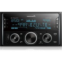
- CAUTION
- NOTE
- INFORMATION TO USER
- WARNING
- VENTILATION CAUTION
- OPERATING ENVIRONMENT
- IMPORTANT SAFETY INSTRUCTIONS
- IMPORTANT NOTICE
- (SYMBOL EXAMPLES FOR BATTERIES)
- CONTENTS
- 01 CONTROLS AND DISPLAYS
- 02 CONNECTING YOUR EQUIPMENT
- 03 BASIC SETUP
- 04 BASIC PLAYBACK
- 05 LISTENING TO YOUR SYSTEM
- 06 THE SYSTEM SETUP MENU
- 07 CONTROL WITH HDMI FUNCTION
- 08 CONTROLLING THE REST OF YOUR SYSTEM
- 09 ADDITIONAL INFORMATION
- BEFORE YOU START
- CHECKING WHAT'S IN THE BOX
- INSTALLING THE RECEIVER
- FLOW OF SETTINGS ON THE RECEIVER
- REQUIRED SETTING ITEM
- SETTING TO BE MADE AS NECESSARY
- 1 CONNECTING THE SPEAKERS
- 2 CONNECTING THE COMPO
- 3 POWER ON
- 4 THE PRE OUT SETTING (PAGE 37)
- 5 USE THE ON-SCREEN AUTOMATIC MCACC SETUP TO SET UP YOUR SYSTEM
- 6 PLAYING A SOURCE (PAGE 22)
- 7 ADJUSTING THE SOUND AS DESIRED
- 8 MAKING MAXIMUM USE OF THE REMOTE CONTROL
- CHAPTER 1: CONTROLS AND DISPLAYS
- 1 INPUT SELECTOR DIAL
- 2 INDICATORS
- 3 RECEIVER CONTROL BUTTONS
- 4 CHARACTER DISPLAY
- 5 TUNER CONTROL BUTTONS
- 6 REMOTE SENSOR
- 7 MASTER VOLUME DIAL
- 8 STANDBY/ON
- 9 PHONES JACK
- CONTROLS AND DISPLAYS
- 10 LISTENING MODE BUTTONS
- 11 MCACC SETUP MIC JACK
- 12 AUDIO/VIDEO INPUT TERMINAL
- 13 IPOD IPHONE IPAD/USB TERMINAL
- 14 SOUND RETRIEVER AIR
- 15 IPOD IPHONE IPAD DIRECT CONTROL
- DISPLAY
- 16 PHASE
- 17 AUTO
- 18 TUNER/SIRIUS INDICATORS
- 19 SPEAKER INDICATORS
- 20 SLEEP TIMER INDICATOR
- 21 PRESET INFORMATION OR INPUT SIGNAL INDICATOR
- 22 CHARACTER DISPLAY
- 23 DTS INDICATORS
- 24 DOLBY DIGITAL INDICATORS
- 25 ADV.S
- 26 SIGNAL SELECT INDICATORS
- 27 UP MIX/DIMMER INDICATOR
- 28 DIR
- REMOTE CONTROL
- 1 SLEEP
- 2 RECEIVER
- 3 RECEIVER
- 4 INPUT SELECT
- 5 INPUT FUNCTION BUTTONS
- 6 LISTENING MODE BUTTONS
- 7 SYSTEM SETUP AND COMPONENT CONTROL BUTTONS
- PRESS RECEIVERCESS
- 8 ↑/↓←/→ (TUNE ↑/↓, PRESET ←/→), ENTER
- 9 COMPONENT CONTROL BUTTONS
- 10 NUMBER BUTTONS AND OTHER COMPONENT CONTROLS
- 11 SOURCE
- 12 TV CONTROL BUTTONS
- 13 MASTER VOLUME
- 14 MUTE
- 15 DISP
- 16SHIFT
- LOADING THE BATTERIES
- OPERATING RANGE OF REMOTE CONTROL
- CHAPTER 2: CONNECTING YOUR EQUIPMENT
- PLACING THE SPEAKERS
- HINTS ON THE SPEAKER PLACEMENT
- IMPORTANT
- CONNECTING YOUR EQUIPMENT
- CONNECTING THE SPEAKERS
- BARE WIRE CONNECTIONS
- CONNECT THE SURROUND BACK OR FRONT HEIGHT SPEAKERS
- SWITCHING THE SPEAKER SYSTEM
- MAKING CABLE CONNECTIONS
- HDMI CABLES
- ABOUT HDMI
- ANALOG AUDIO CABLES
- DIGITAL AUDIO CABLES
- VIDEO CABLES
- STANDARD RCA VIDEO CABLES
- COMPONENT VIDEO CABLES
- ABOUT VIDEO OUTPUTS CONNECTION
- CONNECTING A TV AND PLAYBACK COMPONENTS
- CONNECTING USING HDMI
- CONNECTING YOUR COMPONENT WITH NO HDMI TERMINAL
- CONNECTING A SATELLITE RECEIVER OR OTHER DIGITAL SET-TOP BOX
- CONNECTING AN HDD/DVD RECORDER, BLU-RAY DISC RECORDER AND OTHER VIDEO SOURCES
- USING THE COMPONENT VIDEO JACKS
- CONNECTING OTHER AUDIO COMPONENTS
- CONNECTING OPTIONAL BLUETOOTH® ADAPTER
- CONNECT A BLUETOOTH ADAPTER TO THE ADAPTER PORT TERMINAL ON THE REAR PANEL
- CONNECTING YOUR SIRIUSCONNECT™ TUNER
- CONNECT A SIRIUSCONNECT TUNER TO THE SIRIUS IN JACK ON THE REAR PANEL
- CONNECTING ANTENNAS
- USING EXTERNAL ANTENNAS
- TO IMPROVE FM RECEPTION
- TO IMPROVE AM RECEPTION
- CONNECTING TO THE FRONT PANEL VIDEO TERMINAL
- CONNECTING AN IPOD
- CONNECTING A USB DEVICE
- PLUGGING IN THE RECEIVER
- CHAPTER 3: BASIC SETUP
- CANCELING THE DEMO DISPLAY
- AUTOMATICALLY SETTING UP FOR SURROUND SOUND (MCACC)
- 1 SWITCH ON THE RECEIVER AND YOUR TV
- 4 PRESS RENDEMOTE CONTROL, THEN PRESS THE
- SETUP BUTTON
- 5 SELECT 'AUTO MCACC' FROM THE SYSTEM SETUP MENU, THEN PRESS ENTER
- 6 FOLLOW THE INSTRUCTIONS ON-SCREEN
- BASIC SETUP
- 7 WAIT FOR THE TEST TONES TO FINISH
- 8 CONFIRM THE SPEAKER CONFIGURATION
- 9 MAKE SURE 'OK' IS SELECTED, THEN PRESS ENTER
- 10 THE AUTO MCACC SETUP HAS FINISHED! YOU RETURN TO THE SYSTEM SETUP MENU
- OTHER PROBLEMS WHEN USING THE AUTO MCACC SETUP
- CHAPTER 4: BASIC PLAYBACK
- PLAYING A SOURCE
- 4 PRESS AUTO/DIRECT TO SELECT 'AUTO SURROUND' AND START PLAYBACK OF THE SOURCE
- 5 USE MASTER VOLUME TO ADJUST THE VOLUME LEVEL
- SELECTING THE AUDIO INPUT SIGNAL
- PRESS PRESS SIGNAL SEL TO SELECT THE
- BASIC PLAYBACK
- TIP
- PLAYING AN IPOD
- 2 SWITCH THE TV INPUT TO THE INPUT THAT CONNECTS THIS RECEIVER TO THE TV THROUGH THE CORRESPONDING COMPOSITE OR COMPONENT CABLE
- 4 USE TOP MENU TO DISPLAY IPOD TOP MENU
- PLAYING BACK FILES STORED ON AN IPOD
- FINDING WHAT YOU WANT TO PLAY
- BASIC PLAYBACK CONTROLS
- WATCHING PHOTOS AND VIDEO CONTENT
- PLAYING A USB DEVICE
- IPOD USB
- COMPRESSED AUDIO COMPATIBILITY
- OTHER COMPATIBILITY INFORMATION
- ABOUT MPEG-4 AAC
- ABOUT WMA
- BLUETOOTH® ADAPTER FOR WIRELESS ENJOYMENT OF MUSIC
- WIRELESS MUSIC PLAY
- REMOTE CONTROL OPERATION
- PAIRING THE BLUETOOTH ADAPTER AND BLUETOOTH WIRELESS TECHNOLOGY DEVICE
- 1 PRESS TOP MENU
- LISTENING TO MUSIC CONTENTS OF BLUETOOTH WIRELESS TECHNOLOGY DEVICE WITH YOUR SYSTEM
- LISTENING TO SATELLITE RADIO
- LISTENING TO SIRIUS RADIO
- PRESS SIRIUS TO SWITCH TO THE SIRIUS INPUT
- SELECTING CHANNELS AND BROWSING BY GENRE
- PRESS / TO SELECT THE CHANNEL. IN THE NEXT 2 SECONDS, THE RADIO BROADCAST IS AUTOMATICALLY TUNED IN
- SAVING CHANNEL PRESETS
- 1 SELECT THE CHANNEL YOU WANT TO MEMORIZE
- 2 PRESS T.EDIT
- 4 PRESS ENTER
- LISTENING TO CHANNEL PRESETS
- PRESS ← / → TO SELECT THE CHANNEL PRESET YOU WANT
- USING THE SIRIUS MENU
- 2 USE / TO SELECT A MENU ITEM THEN PRESS ENTER
- 3 WHEN YOU'RE FINISHED PRESS TOP MENU TO RETURN TO THE RECEPTION DISPLAY
- LISTENING TO THE RADIO
- 1 PRESS TUNER TO SELECT THE TUNER
- 3 TUNE TO A STATION
- AUTOMATIC TUNING
- MANUAL TUNING
- HIGH SPEED TUNING
- IMPROVING FM SOUND
- PRESS BAND TO SELECT FM MONO
- SAVING STATION PRESETS
- 1 TUNE TO A STATION YOU WANT TO MEMORIZE
- 2 PRESS TUNER EDIT
- 3 PRESS PRESET ← / → TO SELECT THE STATION PRESET YOU
- LISTENING TO STATION PRESETS
- PRESS PRESET ← / → TO SELECT THE STATION PRESET YOU WANT
- NAMING PRESET STATIONS
- 1 CHOOSE THE STATION PRESET YOU WANT TO NAME
- 2 PRESS TUNER EDIT TWICE
- 3 INPUT THE NAME YOU WANT
- LISTENING TO YOUR SYSTEM
- CHAPTER 5: LISTENING TO YOUR SYSTEM
- CHOOSING THE LISTENING MODE
- AUTO PLAYBACK
- 4 NOTE
- LISTENING IN SURROUND SOUND
- USING THE ADVANCED SURROUND
- F.S.S.ADVANCE
- S.R AIR
- PHONES SURR
- USING STREAM DIRECT
- AUTO
- SURROUND
- USING THE SOUND RETRIEVER
- LISTENING WITH ACOUSTIC CALIBRATION EQ
- BETTER SOUND USING PHASE CONTROL
- PRESS RERIEWPRESS PHASE TO SWITCH THE P.CTL (PHASE CONTROL) ON OR OFF
- USING SURROUND BACK CHANNEL PROCESSING
- PRESS SB/PRESS SB CH REPEATEDLY TO CYCLE THE SURROUND BACK CHANNEL OPTIONS
- SETTING THE UP MIX FUNCTION
- 1 SWITCH THE RECEIVER INTO STANDBY
- 2 WHILE HOLDING DOWN PRESET ⇒ ON THE FRONT PANEL, AND HOLD THE STANDBY/ONFOR ABOUT TWO SECONDS
- SETTING THE AUDIO OPTIONS
- 1 PRESSPRESS AUDIOPARAMETER BUTTON
- MAKING AN AUDIO OR A VIDEO RECORDING
- CHAPTER 6: THE SYSTEM SETUP MENU
- USING THE SYSTEM SETUP MENU
- 3 PRESS RBENRRESS SETUP
- 4 SELECT THE SETTING YOU WANT TO ADJUST
- MANUAL SP SETUP
- MANUAL SPEAKER SETUP
- Q IMPORTANT
- SPEAKER SETTING
- 1 SELECT 'MANUAL SP SETUP' FROM THE SYSTEM SETUP MENU
- 3 CHOOSE THE SET OF SPEAKERS THAT YOU WANT TO SET THEN SELECT A SPEAKER SIZE
- THE SYSTEM SETUP MENU
- CROSSOVER NETWORK
- CHANNEL LEVEL
- 5 ADJUST THE LEVEL OF EACH CHANNEL USING / ⇒
- 6 WHEN YOU'RE FINISHED, PRESS RETURN
- SPEAKER DISTANCE
- 3 ADJUST THE DISTANCE OF EACH SPEAKER USING ← / →
- 4 WHEN YOU'RE FINISHED, PRESS RETURN
- THE INPUT ASSIGN MENU
- 1 SELECT 'INPUT ASSIGN' FROM THE SYSTEM SETUP MENU
- 2 SELECT 'COMPONENT INPUT' FROM THE INPUT ASSIGN MENU
- 3 SELECT THE NUMBER OF THE COMPONENT VIDEO INPUT TO WHICH YOU'VE CONNECTED YOUR VIDEO COMPONENT
- 4 SELECT THE COMPONENT THAT CORRESPONDS WITH THE ONE YOU CONNECTED TO THAT INPUT
- 5 WHEN YOU'RE FINISHED, PRESS RETURN
- THE PRE OUT SETTING
- THE AUTO POWER DOWN MENU
- THE FL DEMO MODE MENU
- CHAPTER 7: CONTROL WITH HDMI FUNCTION
- SYNCHRONIZED AMP MODE
- POWER SYNCHRONIZATION WITH TV
- AUTOMATIC SWITCHING OF INPUTS
- MAKING CONTROL WITH HDMI CONNECTIONS
- HDMI SETUP
- 4 SELECT 'HDMI SETUP' FROM THE SYSTEM SETUP MENU
- 5 SELECT THE 'CONTROL' SETTING YOU WANT
- CONTROL WITH HDMI FUNCTION
- 6 SELECT THE 'ARC' SETTING YOU WANT
- 7 WHEN YOU'RE FINISHED, PRESS RETURN
- BEFORE USING SYNCHRONIZATION
- 1 PUT ALL COMPONENTS INTO STANDBY MODE
- ABOUT SYNCHRONIZED OPERATIONS
- ABOUT CONNECTIONS WITH A PRODUCT OF A DIFFERENT BRAND THAT SUPPORTS THE CONTROL WITH HDMI FUNCTION
- CAUTIONS ON THE CONTROL WITH HDMI FUNCTION
- CHAPTER 8: CONTROLLING THE REST OF YOUR SYSTEM
- SETTING THE REMOTE TO CONTROL OTHER COMPONENTS
- SELECTING PRESET CODES DIRECTLY
- CLEARING ALL THE REMOTE CONTROL SETTINGS
- DEFAULT PRESET CODES
- CONTROLLING THE REST OF YOUR SYSTEM
- CONTROLS FOR TVS
- CONTROLS FOR OTHER COMPONENTS
- BUTTON(S)
- FUNCTION
- PRESET CODE LIST
- TV
- 一
- BD
- HDR)
- DVR (BDR, HDR)
- THE DVD.BD
- VCR
- CHAPTER 9: ADDITIONAL INFORMATION
- TROUBLESHOOTING
- GENERAL
- THE POWER DOES NOT TURN ON
- THE RECEIVER SUDDENLY SWITCHES OFF
- THE POWER SUDDENLY TURNS ON OR OFF, OR THE INPUT SUDDENLY CHANGES (WHEN THE CONTROL WITH HDMI IS ON)
- OVERHEAT SHOWS IN THE DISPLAY AND THE POWER TURNS OFF. → THE TEMPERATURE WITHIN THE UNIT HAS EXCEEDED THE ALLOWABLE VALUE. TRY MOVING THE UNIT FOR BETTER VENTILATION (SEE PAGE 2) → LOWER THE VOLUME LEVEL. TEMP SHOWS IN THE DISPLAY AND THE VOLUME LEVEL DROPS
- NO SOUND IS OUTPUT WHEN AN INPUT FUNCTION IS SELECTED. → USE MASTER VOLUME TO TURN UP THE VOLUME
- NO IMAGE IS OUTPUT WHEN AN INPUT FUNCTION IS SELECTED
- NO SOUND FROM SUBWOOFER
- NO SOUND FROM SURROUND OR CENTER SPEAKERS
- THE PHASE CONTROL FEATURE DOESN'T SEEM TO HAVE AN AUDIBLE EFFECT
- CONSIDERABLE NOISE IN RADIO BROADCASTS
- BROADCAST STATIONS CANNOT BE SELECTED AUTOMATICALLY
- NO SOUND IS OUTPUT OR A NOISE IS OUTPUT WHEN SOFTWARE WITH DTS IS PLAYED BACK
- THERE SEEMS TO BE A TIME LAG BETWEEN THE SPEAKERS AND THE OUTPUT OF THE SUBWOOFER
- AFTER USING THE AUTO MCACC SETUP, THE SPEAKER SIZE SETTING (LARGE OR SMALL) IS INCORRECT
- ADDITIONAL INFORMATION
- CAN'T OPERATE THE REMOTE CONTROL
- THE DISPLAY IS DARK OR OFF
- THE FRONT PANEL DISPLAY SWITCHES OVER FOR NO APPARENT REASON TO VARIOUS DIFFERENT DISPLAYS
- THE RECEIVER DOESN'T RECOGNIZE IPOD TOUCH/IPHONE
- THE BLUETOOTH WIRELESS TECHNOLOGY DEVICE CANNOT BE CONNECTED OR OPERATED. SOUND FROM THE BLUETOOTH WIRELESS TECHNOLOGY DEVICE IS NOT EMITTED OR THE SOUND IS INTERRUPTED
- HDMI
- NO PICTURE OR SOUND
- NO PICTURE
- THE OSD SCREEN (SYSTEM SETUP MENU OR THE MENU SCREEN FOR THE IPOD/USB) ISN'T DISPLAYED
- NO SOUND, OR SOUND SUDDENLY CEASES
- SYNCHRONIZED OPERATION NOT POSSIBLE USING CONTROL WITH HDMI FUNCTION
- IMPORTANT INFORMATION REGARDING THE HDMI
- CONNECTION
- CONFIGURATION
- IPOD MESSAGES
- IPOD/USB ERROR 1 (I/U ERR1)
- IPOD/USB ERROR 3 (I/U ERR3)
- IPOD/USB ERROR 2 (I/U ERR2)
- NO TRACK
- USB MESSAGES
- POD/USB ERROR 1 (I/U ERR1)
- IPOD/USB ERROR 4 (I/U ERR4)
- SIRIUS RADIO MESSAGES
- NO ANT
- CHECK SIRIUS TUNER
- NO SIG
- SUB UPDT
- UPD
- INVLD CH
- ABOUT IPOD/IPHONE/IPAD
- RESETTING THE MAIN UNIT
- 3 WHEN YOU SEE RESET? APPEAR IN THE DISPLAY, PRESS AUTO SURROUND/STREAM DIRECT
- 4 PRESS ALC/STANDARD SURR TO CONFIRM
- CLEANING THE UNIT
- SPECIFICATIONS
- AMPLIFIER SECTION
- AUDIO SECTION
- VIDEO SECTION
- TUNER SECTION
- DIGITAL IN/OUT SECTION
- MISCELLANEOUS
- FURNISHED PARTS
- THE SAFETY OF YOUR EARS IS IN YOUR HANDS
- ESTABLISH A SAFE LEVEL
- BE SURE TO OBSERVE THE FOLLOWING GUIDELINES
- MAGNÉTOSCOPE
- A PROPOS DE I'IPOD/IPHONE/IPAD
- 7 DIAL MASTER VOLUME
- 9 CONECTOR PHONES
- 11 CONECTOR MCACC SETUP MIC
- 1 PULSE FREQUENCY PULSE BOLT AUDIO PARAMETER
- 3 PULSE ROPULSE SETUP
- PIONEER ELECTRONICS OF CANADA, INC
- PIONEER ELECTRONICS (USA) INC
- LIMITED WARRANTY NLY. IN COUNTRY OF PR
- WARRANTY
- PIONEER
- PIONEER ELECTRONIQUES DU CANADA, INC
- PIONEER EUROPE NV
- PIONEER ELECTRONICS ASIACENTRE PTE. LTD
- PIONEER ELECTRONICS AUSTRALIA PTY. LTD
- PIONEER ELECTRONICS DE MEXICO S.A. DE C.V
Brand : PIONEER
Model : VSX821K
Category : AV receiver