
Edition Two - Receiver MAGNAT - Free user manual and instructions
Find the device manual for free Edition Two MAGNAT in PDF.
| Product type | 2-channel stereo power amplifier |
| Brand | Magnat |
| Model | Edition Two |
| Maximum output power (4 Ω) | 2 × 150 W / 1 × 500 W (bridged) |
| RMS power (4 Ω) | 2 × 55 W / 1 × 150 W (bridged) |
| Maximum output power (2 Ω) | 2 × 250 W |
| RMS power (2 Ω) | 2 × 75 W |
| Speaker impedance (stereo) | 2 - 8 Ω |
| Frequency response | 5 - 50,000 Hz (-3 dB) |
| Total harmonic distortion | < 0.08% at 1 kHz |
| Crosstalk attenuation | > 60 dB at 1 kHz |
| Signal-to-noise ratio | > 100 dB (IEC A) |
| LOW LEVEL input sensitivity | 0.4 - 4 V |
| LOW LEVEL input impedance | 20 kΩ |
| Low-pass filter | 40 - 300 Hz, 12 dB/octave |
| High-pass filter | 40 - 300 Hz, 12 dB/octave |
| Bass Boost | 0 - 12 dB at 45 Hz |
| Power supply | 12 V (10 - 15 V), negative ground |
| Fuse | 1 × 20 A |
| Dimensions (W × H × D) | 221 × 57 × 236 mm |
| Weight | 2.1 kg |
| Special features | Automatic on/off, bridgeable operation, Tri-mode, additional RCA outputs, short-circuit and overload protection |
Frequently Asked Questions - Edition Two MAGNAT
User questions about Edition Two MAGNAT
0 question about this device. Answer the ones you know or ask your own.
Ask a new question about this device
Download the instructions for your Receiver in PDF format for free! Find your manual Edition Two - MAGNAT and take your electronic device back in hand. On this page are published all the documents necessary for the use of your device. Edition Two by MAGNAT.
USER MANUAL Edition Two MAGNAT
EDITION TWO EDITION TWO LIMITED
2 KANAL LEISTUNGSVERSTÄRKER 2 CHANNEL POWER AMPLIFIER AMPLIFICATEUR DE PUISSANCE À 2 CANAUX
BEDIENUNGSANLEITUNG/GARANTIEURKUNDE OWNER'S MANUAL/WARRANTY DOCUMENT MODE D'EMPLOI/CERTIFICAT DE GARANTIE
Magnat®

At the end of the product's useful life, please dispose of it at appropriate collection points provided in your country.
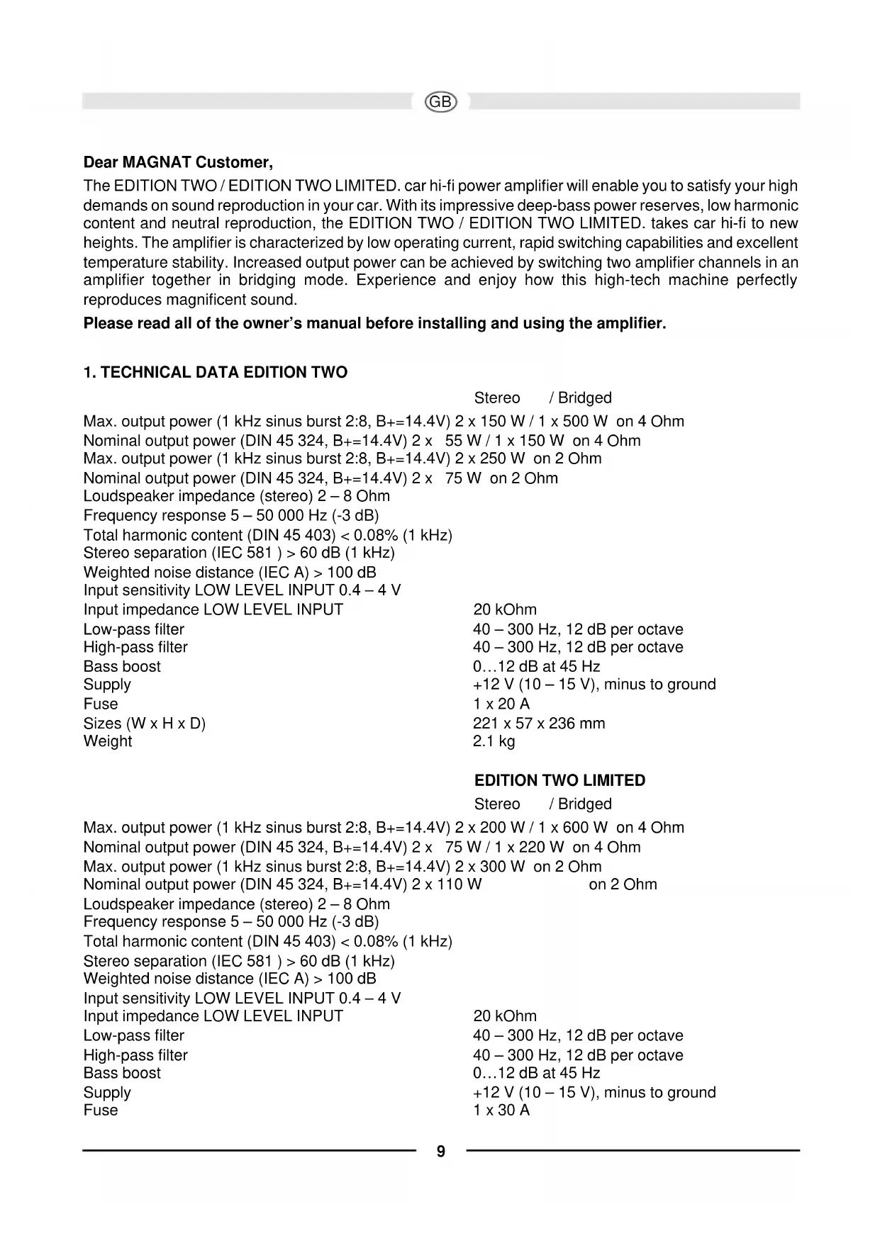
Dear MAGNAT Customer,
The EDITION TWO / EDITION TWO LIMITED. car hi-fi power amplifier will enable you to satisfy your high demands on sound reproduction in your car. With its impressive deep-bass power reserves, low harmonic content and neutral reproduction, the EDITION TWO / EDITION TWO LIMITED. takes car hi-fi to new heights. The amplifier is characterized by low operating current, rapid switching capabilities and excellent temperature stability. Increased output power can be achieved by switching two amplifier channels in an amplifier together in bridging mode. Experience and enjoy how this high-tech machine perfectly reproduces magnificent sound.
Please read all of the owner's manual before installing and using the amplifier.
1. TECHNICAL DATA EDITION TWO
Stereo /Bridged
Max. output power (1 kHz sinus burst 2:8, B_+ = 14.4V 2× 150~W / 1× 500~W on 4 Ohm
Nominal output power (DIN 45 324, B + = 14.4V) 2× 55W / 1× 150W on 4 Ohm
Max. output power (1 kHz sinus burst 2:8, B+=14.4V) 2 x 250 W on 2 Ohm
Nominal output power (DIN 45 324, B + = 14.4V) 2x75W on 2 Ohm
Loudspeaker impedance (stereo) 2-8 Ohm
Frequency response 5 - 50 000 Hz (-3 dB)
Total harmonic content (DIN 45 403) < 0.08% ( 1kHz)
Stereo separation (IEC 581) > 60 dB (1 kHz)
Weighted noise distance (IEC A) >100 dB
Input sensitivity LOW LEVEL INPUT 0.4 - 4V
Input impedance LOW LEVEL INPUT
Low-pass filter
High-pass filter
Bass boost
Supply
Fuse
Sizes (W× H× D)
Weight
20 kOhm
40-300 Hz, 12 dB per octave
40-300 Hz, 12 dB per octave
0...12 dB at 45 Hz
+12 V (10 - 15 V), minus to ground
1x20A
221× 57× 236mm
2.1 kg
EDITION TWO LIMITED
Stereo /Bridged
Max. output power (1 kHz sinus burst 2:8, B + = 14.4V 2× 200W / 1× 600W on 4 Ohm
Nominal output power (DIN 45 324, B + = 14.4V) 2× 75W / 1× 220W on 4 Ohm
Max. output power (1 kHz sinus burst 2:8, B_+ = 14.4V ) 2× 300W on 2 Ohm
Nominal output power (DIN 45 324, B_+ = 14.4V ) 2× 110W on 2 Ohm
Loudspeaker impedance (stereo) 2-8 Ohm
Frequency response 5 - 50 000 Hz (-3 dB)
Total harmonic content (DIN 45 403) < 0.08% ( 1kHz)
Stereo separation (IEC 581) >60 dB (1 kHz)
Weighted noise distance (IEC A) >100 dB
Input sensitivity LOW LEVEL INPUT 0.4 - 4V
Input impedance LOW LEVEL INPUT
Low-pass filter
High-pass filter
Bass boost
Supply
Fuse
20 kOhm
40-300 Hz, 12 dB per octave
40-300 Hz, 12 dB per octave
0...12 dB at 45 Hz
+12 V (10 - 15 V), minus to ground
1x30A
Sizes (W× H× D)
221× 57× 236mm
Weight 2.15kg
SUBJECT TO TECHNICAL CHANGE
2. FEATURES
- Complementary push-pull final stage
Automatic switching on/off via car radio - Infinitely adjustable high pass and low pass filters
- Infinitely variable bass equalisation
- Adjustable input sensitivity
- Bridgeable 2-/1-channel mode
- Tri-mode
- Electronic protective circuit against short circuiting, DC offset and excess temperature
- Mute switch for suppressing switch-on crackle interference
- Low-level outputs (cinch jacks) for connecting additional amplifiers
- Operating display (green LED) and overload indicator (red LED)
3. IMPORTANT INSTALLATION INFORMATION
- This appliance may only be connected to a 12 volt system with negative ground.
- The heat radiated when the amplifier is used means that sufficient air circulation is required at the place of installation. It is very important that the cooler's cooler ribs do not contact any metal plating or any surfaces which could impair air circulation. The amplifier may not be installed in small confined spaces or spaces without air circulation (e.g. spare wheel recess or under the vehicle carpeting). Installation in the boot is recommended.
- Install the amplifier in such a way that it is protected as far as possible against vibrations and dust and dirt.
- Make sure that the input/output cables are sufficiently distant from the power supply cables as otherwise interference may occur.
- Make sure that the fuse and operating elements are accessible after installation.
- The appliance's reliability and performance depend on the quality of installation. Preferably get an expert to install the system, particularly if you want to install several loudspeakers or a complex multi-way system.
4. CONNECTIONS
4.1 POWER SUPPLY AND AUTOMATIC SWITCHING ON
Important notice: Before commencing the installation, disconnect the plus terminals from the car battery in order to prevent short circuits.
The power cabling usually installed in on-board car networks is not sufficient for a power amplifier's demands. Make sure that the power lines to GND and to the +12V terminal have been sufficiently specified. A cable cross-section of at least 10mm^2 must be used to connect the battery to the amplifier's terminals.
First connect the amplifier's GND terminal to the battery's minus pole. It is very important that the connection is good. Dirt residues must be carefully removed from the battery's connection point. A loose connection may cause malfunctions or interference noise or distortion.
The +12V amplifier connection must then be connected with a power cable possessing an integrated fuse to the battery's plus pole. The fuse must be located close to the battery, the length of cable from the battery's positive pole to the fuse must be less than 60 centimetres for safety reasons. Only insert the fuse when all installation work, including the connection of the loudspeakers, has been completed.
Now connect the car hi-fi receiver's remote control connection to the amplifier's REM control jack. Acable with a cross-section of 0.75mm^2 is sufficient for connecting the amplifier's REMOTE connection and the control device.
4.2 AUDIO CABLES
When installing the audio cable between the cinch output of your car receiver and the cinch input of the amplifier inside your car, the audio and power supply cables should, wherever possible, not be routed along the same side of the vehicle. We recommend an isolated installation, e.g. routing the power cable through the cable duct on the left-hand side and the audio cable through the cable duct on the right-hand side or vice versa. This reduces interference due to crosstalk into the audio cables.
4.3 LOUDSPEAKER CONNECTIONS
- In normal operating mode (i.e. one loudspeaker on each individual amplifier channel), the lowest terminal resistance is 2 ohm per channel.
In bridging mode (two amplifier outputs combined) the lowest terminal resistance doubles to 4 ohm. - The impedance in tri-mode may not fall below 2 ohm per channel.
- Never connect the loudspeakers' minus terminals to the vehicle chassis.
- Never connect the +12V supply voltage to a loudspeaker output as this would destroy the amplifier final stage.
If the amplifier is operated with lower terminal resistances or incorrectly used as described above, both the amplifier and the loudspeakers may be damaged. The warranty becomes void in such cases.
5. OPERATING ELEMENTS AND IN/OUTPUTS
5.1 SETTING THE INPUT SENSITIVITY
The input sensitivity may be adapted to any car radio or tape deck. Turn the volume control of your radio to its central position and then adjust the input-level control (5) to produce an average medium volume. This setting usually provides sufficient power reserves at optimum weighted noise voltage.
ATTENTION: only reproduce loud test noises briefly to prevent damaging the loudspeakers.
5.2 LOW-PASS FILTER WITH ADJUSTABLE CROSS-OVER FREQUENCY
If the amplifier is used as a subwoofer amplifier, set the switch (3) to "LPF". Set the desired cross-over frequency with the control (4). This makes the filter adaptable to the installed woofer's sound requirements.
The filter's high edge steepness is responsible for the precision reduction of medium and high frequency ranges.
5.3 HIGH-PASS FILTER WITH ADJUSTABLE CROSS-OVER FREQUENCY
If the amplifier is to be used as an amplifier for satellite loudspeakers (mid-range/tweeter loudspeakers), set switch (3) to "HPF". Set the desired cross-over frequency with the control (4). Only the frequencies above the set cross-over frequency will then be amplified. This effectively minimizes distortions caused by excessive membrane movement at low frequencies and small satellite loudspeakers without reducing the bass level.
5.4 BASS-BOOST
The bass-boost function (2) is used to increase or equalize the lower bass frequencies.
5.5 OUTPUTS FOR CONNECTING ADDITIONAL AMPLIFIERS
The input signal of the INPUT connections L and R (1) is forwarded directly to the OUTPUT (7) Land R jacks. The OUTPUTconnections allow the use of additional amplifiers without requiring additional T-plugs and cables.
FIG. 1 POWER SUPPLY / REMOTE SWITCH-ON CONNECTION
(1) GND terminal for the ground, to the battery's minus pole
(2) REM terminal for remote switch-on
(3) Terminal for +12V battery voltage
(4) Battery
(5) Cable fuse
(6) To your car radio's automatic aerial connection If your car is not equipped with an automatic aerial connection, connect this cable's plus pole (+) to the ignition lock. An on/off switch should be inserted in this case. Make sure that this switch is switched off if the amplifier is not used.
FIG. 2 STEREO MODE
Connect and set the amplifier as shown in Fig. 2 if it is to be controlled with two output channels and to use two loudspeakers. The high-pass filter must also be activated if the amplifier is also used for satellite loudspeakers. See Chapter 5.3.
(1) To the car radio, left output
(2) To the car radio, right output
(3) Loudspeaker left
(4) Loudspeaker right
FIG. 3 BRIDGE MODE WITH STEREO CAR RADIO
If the amplifier has to generate more power to operate a subwoofer, connect and set it as shown in Fig. 3. The use of the low-pass filter is described in Chapter 5.2.
(1) To the car radio, left output
(2) To the car radio, right output
(3) Subwoofer
FIG. 4 MONO MODE WITH ONE CAR RADIO WITH SUBWOOFER OUTPUT
(1) To the car radio, subwoofer output
(2) Subwoofer
FIG. 5 OPERATING ELEMENTS AND IN/OUTPUTS
(1) Low-level input
(2) Bass-booster control
(3) Linear (FULL)/ low pass filter (LPF)/ high pass filter (HPF) option switch
(4) Cross-over frequency control for low pass / high pass
(5) Input-level control
(6) Mono-stereo switch
(7) Outputs for connecting additional amplifiers
Très cher client de MAGNAT
Bass Boost 0...12 dB a 45 Hz
Suministro +12V (10 - 15 V), negativo a tierra
Fusible 1 × 30 A
Dimensiones (A x A x P) 221 x 57 x 236 mm
Peso 2,15 kg
Bass boost 0...12 dB com 45 Hz
4.3 HÖGTALARANSLUTNINGAR
1. TEXHnueCKNE DAHHbIE
| Makc. BixoHaj Mochocb (1 kTc Sinus Burst 2:8, B+=14,4B) |
| HomnHaJIbHaj BixoHaj Mochocb (DIN 45 324, B+=14,4B) |
| Makc. BixoHaj Mochocb (1 kTc Sinus Burst 2:8, B+=14,4B) |
| HomnHaJIbHaj BixoHaj Mochocb (DIN 45 324, B+=14,4B) |
| POnHoe conpoTnbHeHne rpOMKOrOBopnten (ctpeopeKIM) |
| YactOTHaj xapaKTepcntka |
| O6uŋ Ko3ΦΦηηHT HeLHeHbIX NckaKeHη (DIN 45 403) |
| IpeXeOHDHe 3aTyxHne (IEC 581 ) |
| OTHOSeHne CunHaJ/Σym (IEC A) |
| UByCTBNTbHocb Ha BxOe LOW LEVEL INPUT |
| BxOHDHe NoNHOe conpoTnbHeHne LOW LEVEL INPUT |
| ΦnNbTp HnXhNx YactOT |
| ΦnNbTp BepXhNx YactOT |
| YcnIeHne Hn3Knx YactOT |
| ΠιTaHne |
| ΠρεθοχραHnteNb |
| Pa3Mepbl (Πx B x Γ) |
| Bec |
EDITION TWO
| Стейко / черснистуку |
| 2 x 150 BT / 1 x 500 BT κ 4 OM |
| 2 x 55 BT / 1 x 150 BT κ 4 OM |
| 2 x 250 BT κ 2 OM |
| 2 x 75 BT κ 2 OM |
| 2 - 8 OM |
| 5 - 50 000 Гu (-3 дБ) |
| < 0,08% (1 кгu) |
| > 60 дБ (1 кгu) |
| > 100 дБ |
| 0,4 - 4 B |
| 20 кOM |
| 40 - 300 Гu, 12 дБ на okтаву |
| 40 - 300 Гu, 12 дБ на okтаву |
| 0...12 дБ пи 45 Гu |
| +12 B (10 - 15 B), минус на масce |
| 1 x 20 A |
| 221 x 57 x 236 мм |
| 2,1 кг |
| MaKc. BbIXOHaH MaOuHocTb (1 KΓu Sinus Burst 2:8, B+=14,4B) |
| HomHaJIbHаr BbIXOHaH MoUHocTb (DIN 45 324, B+=14,4B) |
| MaKc. BbIXOHaH MoUHocTb (1 KΓu Sinus Burst 2:8, B+=14,4B) |
| HomHaJIbHаr BbIXOHaH MoUHocTb (DIN 45 324, B+=14,4B) |
| ПОЛhoe CONPOTIBeHne rPOMKOrOBOpITeHn (CTepeopeXm) |
| YacToTHa XapaKTePncTnka |
| ОБцИй Ko3ФФицHeNТ HeIиHeNHy bIX NcKaJxHn (DIN 45 403) |
| IpePexOДhoe 3aTyxHnne (IEC 581 ) |
| OTHOseHne CnIHaI/шуM (IEC A) |
| ЧУВСТВИТЕЛьНOCТь Ha BXОд LOW LEVEL INPUT |
EDITION TWO LIMITED
| Ctepeo / uepe3 nepeMbIky | |
| 2 x 200 Bt / 1 x 600 Bt κ 4 Om | |
| 2 x 75 Bt / 1 x 220 Bt κ 4 Om | |
| 2 x 300 Bt | κ 2 Om |
| 2 x 110 Bt | κ 2 Om |
| 2 - 8 Om | |
| 5 - 50 000 Γι (-3 έБ) | |
| < 0,08% (1 κΓι) | |
| > 60 έБ (1 κΓι) | |
| > 100 έБ | |
| 0,4 - 4 B | |
Bxohoe nonhoe conpoTnBneHne LOW LEVEL INPUT
20 kOM
ΦHbTp HxhHxuACTOT
40-300T,12DHaOKTaby
ΦHbTp BepxHnx YactOT
40-300T,12DHaOKTaby
YCNHNEHN3KHXACTOT
0...12Dpnp45
Ntahne
+12B(10-15B),MnHycHaMacce
PpeOxpaHnteB
1×30A
Pa3Mepbl (UxxBxΓ)
221 × 57 × 236 MM
Bec
2.15K
BO3MOXHbI TEXHNueCKNE N3MEHEHNA
2.OCO6EHHOCTN
- DOnONHHTeBHyI DByXTaKTHbI BbIXoHOKacka
ABTOMaTnueckoe BkHoueHne/BbIKHoueHne Yepe3 aBTOpaIOnnpMnK
PiabHO perynpemybIe pbltpbBepxHnx HnKHX qactOT - PnabHo peryIpyemar KoppeKmHn3Knx qactOT
Perynpemyam yBCTBntbHocTb Ha BXOe
Bo3MOXHOCTb nepembKaHn, 2-/1-kaHaNbHbI-pexHM
TpIMoI-peKmM (Tri-Mode)
3neKtpoHHa CXema 3auntbI OT KopoTKoro 3ambikaHn, CMeueHn NOCTOHHORO HanpJxehn n neperpeBa
Hemar cxema nnoabneHH Tpecka npn BkIouehnn
BbIXoDb C Hn3KIM yPOBHeM nepeKnHueHn (CInch-rHe3da) dna noKnHouHn eoONHnteJbHbX ycunTenei
Hdkkaqma pexima (3eHbI CBeToNO) npeperpy3Kn (KpachbI CBeToNO)
3. BAXKHAR INHΦOPMAUINI NEPED YCTAHOBKOJ
TO yCTPOINCTBO npedHa3HaueHo NCKIOHTeBHO nnoKIOUeHn K 12-BoIbTHo CNTeMe COTpuATeBHOH MAccO.
BcBraC BbIeHnem Tenn np Odae MoHocTH, Ha MeTe dN MaHTaXa DOJXHa 6bITb DOCTaTOHnA UpKyIaIaBIO3dyXa. OueHb BaXHo, YTObI OXNaXdIoUe pe6pa TeNIOOTBOda He Kacannc MetaJIInuecko Hn Dpyro NOBepxHOCTn, n3-3a Yero MOrna 6bl 6blb OrpaHnueHa CnpKyIaIaBIO3dyXa. Henb3y yCTaHabINBaTb ycUNtEnb B MaIbIX INn HE BeHTINPyEmbx NOOCTrx (Hanp., B yrny6neHn dNra 3anaCHoro KOneca INn NOk KOBPOBBIM NOKpbITmE ABTomO6nla). PekomeHdyETc pa3MeuHne B 6baraxHnke.
- YcTaHaBnBaIte ycInTeIb TaKIM o6pa3OM, yTo6bl OH 6bl XopoIo 3aunueH OT Bn6paun, OT NblN rpr3N.
Cneinte 3a tem, yto6bI Ka6enb BxOda/BbxOda HaxoDnnc Ha DoCTaTOHOM pacctoHHN OT Ka6enr 3NeKtponntAHn, TAK KAK 3TO MOKeT npBecT N O6nyeHIO, BB3bBaIOUcEMy NOMEXN.
Cneinte 3a TeM, yTo6bI npedoxpaHntB n opraHbI ynpabHeHnOCTaBAJNCb nocne MOHTaxKa IOCTyINHBIM.
Pa6ota n HadeXHOCTb yCTaHOBKn HAXOHTCBA INPpMoN 3aBNCMOCTN OT KaueCTBa MOHTaKa. Bblno 6bl npednoHTeNbHO npuyHb MoHTaX CneuaNNCTy, Oco6eHHo, ecnn peYb NIdet o6 yCTaHOBKe C HeCKoJIbKIMn rPOMKOROBOpHTeJAMN NN O KOMNJIeKCHOH MHOROCTOPOHHei CNCTeme.
4. BXOdbI N BbIXOdbI
4.1 3JIeKTPoPNTAHNE N ABTOMATNKA BKJIIOUeyHn
Baxnha cbblnka: Ppejde yem hauatb yctaHOky Bbl dONXHbI OTcoeHNHTb NOLOKHTeHbI 3axHM aBTOMO6HbHoro AKyMyJrTopa, TTO6bl H36eKaTb KOpOTkX 3AmbKaHH.
O6bHnA nA BTOMO6nBHO 6OpTOBO CTeN Ka6eNbHa pa3BOkKa YBnETCa HeoCTaTOHOn dna Notpe6hOteM OuHOrO yCnnteIa. CneIte 3a Tem, YTo6bI pa3Mepe bI 3NeKTPoPbOdkn K 3a3emnHoue WHe (GND) n K +12 B-3axmMy 6blnn DoCTaTOHbIMn. Dnra CoednHeHn aKKyMylTopa c 3neKTPnueeckmN 3axmamN ycHNTeIa peKOMeHdyETc npImeHrTa Ka6eNb C nonepueHbIM ceehnem He Mehee 10 MM2.
Chauana Bam Heo6xOIMO CoeHNHTb 3axm 3a3emJIOsei xHbI (GND) ycHNTeJIc MInHycOBoi Klemmo aKymyIaTOPa. Oeyb BaxHO yCTaHOBt npouHoe coeHNHeHne. Klemma aKymyIaTOPHO 6aTpeNdoJXHa 6bITb TuaTeNbHO OuNSeHa OT 3arp3HeHn. CBo6oHDoe COeHNHeHne MOKeT Bb3BaTb c60I NII WymOBble NOMEx N NCKaXeHn 3Byka.
Tenepb 3axn ycnnten ha +12B noedcoeHnaetcra nKtpokaeem c HTERpnpoBaHHbIM npedoxpaHntenm K noonxtelbHO Knemme akymyIaTopa. PpeoxpaHnte bdoJxeh HaxOHTc B6nn3n aKkymyIaTopa, nnHa Ka6ena ot noonxtelbHoro nonoCa akymyIaTopa do npedoxpaHntenr doXnHa coCTabNtB b ceJnx 6e30nacHocTn Mehee 60 cm. PpeoxpaHnte bdoJxeh 6blb ycTaHOBneH nnb nocne 3aBepueHnB Cex paBOT no MOHTaxy, BKnIOUaer noKDIOUeHne rpmKorOBopTe ne.
Tenepb noCoeHnHTe KaebIb DnCTaHcHOnHOrO ynpabHeHna ABTOMObHoro HiFi-npneMHnka K rHe3dy ynpabHeHn REM ycInTeJI. IJra CoeHNHeHn MeKdy BBOdom REMOTE ycInTeJIu ynpabNIOUm yCTpOINCTBOM DOCTaTOeH KaebIb C nonepueHbIM ceEHnEM 0,75 MM2.
4.2 AYDNOKABENb
Pn MOtaxe aydnoka6en MExdy BbIXoDM Cinch abTomobnlbHoro paHonpneMHNka n BXoDM Cinch ycunnteB aBTOMo6nne cneintb 3a TeM, yTo6bl aydnoka6en b TOKONoDBoaIuN Ka6enb NO BO3MOxHOCTn He npoknaDbBaINCb Ha ToJ Xe CTOpOHe ABTOMo6nla. NuyHM peweHem RnTcR OTdeNBbIM MOtaxK, T.e. npoknaKa TOKONoDBOraero Ka6enB NLeBOi Ka6enbHO JaxTe I npoknaKa aydnoka6en B npabOi Ka6enbHOJ axTe HnHaobopot. TaKM O6pa3OM CHXkAEcOnachocb nepekepcTHbIX NOMex 3ByKOBOrO CInHana.
4.3 NOOKJIIOUeHnI rPOMKOrOBOPTEJEn
B HopMaJIbHOM pexnme pa60TbI (T.e. no OdHomy rpoMkoROBOpTeIO Ha oIN HAkan Ycunnten) HaimeHbWee harpy3OuHoe conpOTNBneHne paBHO 2 OM ha oIN KaHAn.
BpeKIme nepeMbIyKn (COBMeCTHOe BKNIOHcHHe NByX BbIXOIOB yCNNTeJIa) HAnMeHbWee Harpy30uHoe cOnpoTnBHeHne yDbaNBAeTCdo 4 OM.
BpeXIMe TpIMoD noJIHoe cOpiOTnBHe He HxHe HxKe 2 OM Ha OIN KaHaJ.
Hn B Koem cnyuae He noocoeHHrTe MmhycoBbI KneMMbl rpmKorOBopnteK WACCn ABTOMO6nJ.
HnB KOem cnyuae He coeunHne HanpJxKeHne nHTAHn+12B c BbIXoOM rpomKorOBopuTeJI. 3TO BeDET K pa3pyuWeHHO BbIXoHOrO KacKaJa yCnIITeJI.
Ecnn ycnntenb 3KcniyaTnpyetc 60onee Hn3kM cnpotnbneHem nn He npabnbo, Kaonncano Bblwe, To 3TO MOxET npBecTN K nobpeJeHIO kak camoro ycunntenra, TAK n rpomkorOBopnten. B 3tOM cnyuae rapaHTna nponaadaet.
5. 3JEMEHTbI CNTcEMbl YNPABJIeHnI BxOdbI/BbIXOdbI
5.1 PEGYINPOBKA YUBCTBNTEJIbHOCTN HA BXODE
UyBCTBNTeJIbHOCTb Ha BXOJe MOXeT 6bIb NIOOrHaHa K JIObOMy ABTomO6nIbHOMy paDNOpNEMHNky Hnn ABTomaHHTone. NobepHnTe peryJrToP rPOMKocTN BaWero paDNOpNEMHnKa Do cpeINbI n HAcTpOIne peYJrToP BXoDHorO yPoBn (5) TakIM o6pa30M, UTO6bl NOnyUnacb CpeHna rPOMKocTb. O6bUHO TaKaJ HAcTpOJa k ObecneuHbaet DOCTaTOUHb Pe3epB MOUHOCTn npn ONTMaJIbHOM OTHOWeHH CNrHaN/WM.
BHIMAHNE: rPOMKne TecrHnbl BKnIOaTb TOnbKO Ha KOpOTKoe Bpemr qTo6bl n36eKaTb NOBpeXdHn rPOMKOrOBopnteJI.
5.2 ΦιλbTp HIXKHX YACTOT C PEGYINPYEMO INEPEXOHOYCACTOTOH
Ecn ycnntenb nCnoB3yETcB KaueCTBe ycHNTeNn Dn rPOMKOROBOPHTeNn Hn3kNx qactOT,TO Bam Heo6xOIMO yctahOBnTb nepeKnIOvateNB (3) Ha LPF. YcTaHOBnTe peryIaTOPOM (4) XeNaemyu nepexoHyu qactOTy. TaKIM o6pa3OM fNtbp MoKeT 6bITb npNCNOco6JHe K 3ByKObbIM notpe6hOCTAm npimeHReMOro rPOMKOROBOpNTeNn Hn3kNx qactOT.
BbICOKa KpyTn3Ha 0pOHTa 0nIbTpTa o6ecneuBaet ToUHOe cHIXeHHe CpeHNx N BbICOKnx Dmana3OHOB YAcTOT.
5.3 ΦиьтВЕХнхЧАСТOT C PEGУЛПУЕМОД ПЕPEXODHОД YACTOTOД
Ecnn ycnntenb npedha3haeH nna nncnb30baHnB kaueCTBe ycunnten da CnyTHNKOBbix rpomkorobopnten (rpomkorobopnten Dnra cpehnx/ Bbcoknx ToHO, To Bbl doJXhbI nepeDbHytb nepeknoyatEnb (3 ha ,HPF". YcTaHOBtpe peryrAToPOM (4) xeJaemyo nepexOndhyo qactoty. Takm 6pa3om BydyT ycIneHbI TOnbKO qAcTObbl BiIwe yctaHOBneHHoN nepexOHDH qactOtbl. TaK MOxHO 3ΦΦeKTHBHO CBeCTN K MHNIMMy UCKaKeHnR, Bbl3BaHHbIe CNIshKOM 6onblmm pa3Maxom MempaHbI npn Hn3kX qAcTOTax N MaIbIX pa3Mepax CnyTHNKOBbIX rpomkorobopnten, He CHNXAR yPOBHA Hn3kX qACTOT.
5.4 YCUNJEHNE HN3KNX YACTOT (BASS-BOOST)
C nOMOsbI nepeKIOUaTeJIy cHJEnHn HN3KNX qACTOT (2) MoKeT 6bITb DOCTnHyTO NOdEePKBaHHe NIN KOPPEKcuaBIX HN3KNX qACTOT.
5.5 BbIXOdbI DnI NOIKNIOUeyHn ApyuX yCNJNTEN
Bxodno cnraan BbOaOB INPUT L n R (1) nepedaetcna HnpanMyo K bixohbim rhe3dAm OUTPUT (7)LnR.BbxoDbI OUTPUT daot Bo3MOXHOCTb NOKIOHEny dpyrnx ycInnteJe 6e3 DononHntenbHoro T-WeKepa n Ka6ena.
PNC.5 3JIEMENTbI CNCTEMbl YNPABJEHn I BXOdbI/BbIXOdbI
(1) BxOD c Hn3Km ypoBHe m nepeKeIIOueHnA
(2) PerynTop Bass Boost
(3) NpeeknouateIb: pHnbTp Huxhnx yactOT (LPF) / nHeHbI (FULL) / pHnbTp BepxHx qactOT (HPF)
(4) PerynTOp nepexoHOn yactObl IJy fNtpa HxKHX xactOT / fNtpa BepxHx xactOT
(5) PerynTOp BxoHoro ypoBHa
(6) NpeeknouateIb MOHO/CTepeo
(7) BbIXoDbI dnn noDknIOUeHn Apynx ycunntenei
尊敬的 Magnat - 用户,
Congratulations! You have made a wise selection in becoming the owner of a MAGNAT HiFi equipment. Due to high quality MAGNAT HiFi products have earned an excellent reputation through the western world. And this high quality standard enables us to grant a 2-years warranty for MAGNAT HiFi-electronic components.
The equipments are checked and tested continuously during the entire production process. In case you have problems with your MAGNAT HiFi equipment, kindly observe the following:
- The guarantee period commences with the purchase of the component and is applicable only to the original owner.
- During the guarantee period we will rectify any defects due to faulty material or workmanship by replacing or repairing the defective part at our discretion. Further claims, and in particular those for price reduction, cancellation of sale, compensation for damages or subsequent damages, are excluded. The guarantee period is not altered by the fact that we have carried out guarantee work.
- Unauthorized tampering with the equipment will invalidate this guarantee.
- Consult your authorized dealer first, if guarantee service is needed. Should it prove necessary to return the component to the factory, please insure that the component is packed in original factory packing in good condition the quality control card has been filled out and enclosed with the component your enclose your receipt as proof of purchase.
- Excld from the guarantee are: - Illuminates - Shipping damages, either readily apparent or concealed (claims for such damages must be lodged immediately with forwarding agent, the railway express office or post office). - Scratches in cases, metal components, front panels, etc. (You must notify your dealer directly of such defects within three days of purchase.) - Defects caused by incorrect installation or connection, by operation errors (see operating instructions), by overloading or by external force. - Equipments which have been repaired incorrectly or modified or where the case has been opened by persons other than us. - Consequential damages to other equipments.
- Reimbursement of cools, without our prior consent, when repairing damages by third parties.
F
Toutes nos félicitations!
Name and address of the dealer/stamp
Käufer/Customer
Name/Name
StraBe/Street
PLZ, Ort/City
Land/Country
Kaufdatum/buying date
No warranty without receipt!


Magnat®

- EDITION TWO EDITION TWO LIMITED
- KANAL LEISTUNGSVERSTÄRKER 2 CHANNEL POWER AMPLIFIER AMPLIFICATEUR DE PUISSANCE À 2 CANAUX
- Dear MAGNAT Customer,
- TECHNICAL DATA EDITION TWO
- EDITION TWO LIMITED
- SUBJECT TO TECHNICAL CHANGE
- FEATURES
- IMPORTANT INSTALLATION INFORMATION
- CONNECTIONS
- POWER SUPPLY AND AUTOMATIC SWITCHING ON
- AUDIO CABLES
- LOUDSPEAKER CONNECTIONS
- OPERATING ELEMENTS AND IN/OUTPUTS
- SETTING THE INPUT SENSITIVITY
- LOW-PASS FILTER WITH ADJUSTABLE CROSS-OVER FREQUENCY
- HIGH-PASS FILTER WITH ADJUSTABLE CROSS-OVER FREQUENCY
- BASS-BOOST
- OUTPUTS FOR CONNECTING ADDITIONAL AMPLIFIERS
- 1 POWER SUPPLY / REMOTE SWITCH-ON CONNECTION
- 2 STEREO MODE
- 3 BRIDGE MODE WITH STEREO CAR RADIO
- 4 MONO MODE WITH ONE CAR RADIO WITH SUBWOOFER OUTPUT
- 5 OPERATING ELEMENTS AND IN/OUTPUTS
- Très cher client de MAGNAT
- HÖGTALARANSLUTNINGAR
- TEXHnueCKNE DAHHbIE
- EDITION TWO
- BO3MOXHbI TEXHNueCKNE N3MEHEHNA
- 2.OCO6EHHOCTN
- BAXKHAR INHΦOPMAUINI NEPED YCTAHOBKOJ
- BXOdbI N BbIXOdbI
- 3JIeKTPoPNTAHNE N ABTOMATNKA BKJIIOUeyHn
- AYDNOKABENb
- NOOKJIIOUeHnI rPOMKOrOBOPTEJEn
- 3JEMEHTbI CNTcEMbl YNPABJIeHnI BxOdbI/BbIXOdbI
- PEGYINPOBKA YUBCTBNTEJIbHOCTN HA BXODE
- ΦιλbTp HIXKHX YACTOT C PEGYINPYEMO INEPEXOHOYCACTOTOH
- ΦиьтВЕХнхЧАСТOT C PEGУЛПУЕМОД ПЕPEXODHОД YACTOTOД
- YCUNJEHNE HN3KNX YACTOT (BASS-BOOST)
- BbIXOdbI DnI NOIKNIOUeyHn ApyuX yCNJNTEN
- PNC.5 3JIEMENTbI CNCTEMbl YNPABJEHn I BXOdbI/BbIXOdbI
- 尊敬的 Magnat - 用户,
- F
- Toutes nos félicitations!
- Käufer/Customer
- Magnat®
Brand : MAGNAT
Model : Edition Two
Category : Receiver