
XO23 - Mixer Omnitronic - Free user manual and instructions
Find the device manual for free XO23 Omnitronic in PDF.
| Product type | Active frequency divider (crossover) for professional audio systems |
| Brand and model | Omnitronic XO-23 |
| Dimensions (H x W x D) | 483 x 147 x 46 mm (19" rack format) |
| Weight | 2 kg |
| Power supply and consumption | 230 V AC, 50 Hz ; 10 W |
| Fuse | T 0.5 A (250 V) |
| Operating modes | 2-way stereo or 3-way mono |
| Input | Mono/stereo via XLR; impedance 300/150 kΩ |
| Output | Mono/stereo via XLR; impedance 300/150 kΩ |
| Crossover frequency range | 45 Hz - 9 kHz (selectable via ×10 switch) |
| Filter | 24 dB/octave |
| Signal-to-noise ratio | > 100 dB |
| Distortion | < 0.05% |
| Input control | Range -∞ to +6 dB |
| Output control | Range -∞ to +12 dB (LOW and HIGH) |
| Special functions | Low Cut (30 Hz), phase inversion (0-180°), Mute button, LED indicators, low sum (Low Sum) |
| Maintenance and cleaning | Disconnect before cleaning; use a soft damp cloth; do not use alcohol or detergents |
| Safety | Protection class I; grounding mandatory; do not open the housing; keep away from moisture |
| Spare parts and repairability | Fuse replacement possible by user (type T 0.5A); other repairs by qualified technician |
Frequently Asked Questions - XO23 Omnitronic
User questions about XO23 Omnitronic
0 question about this device. Answer the ones you know or ask your own.
Ask a new question about this device
Download the instructions for your Mixer in PDF format for free! Find your manual XO23 - Omnitronic and take your electronic device back in hand. On this page are published all the documents necessary for the use of your device. XO23 by Omnitronic.
USER MANUAL XO23 Omnitronic
MULTI-LANGUAGE-INSTRUCTIONS
SAFETY INSTRUCTIONS 16
OPERATING DETERMINATIONS 17
DESCRIPTION 17
INSTALLATION 18
STARTING UP 19
OPERATION 19
CLEANING AND MAINTENANCE 24
TECHNICAL SPECIFICATIONS 24
Français
INTRODUCTION 25
INSTRUCTIONS DE SECURITE 25
EMPLOI SELON LES PRESCRIPIONS 27
DESCRIPTION DE L'APPAREIL 27
INSTALLATION 27
MISE EN MARCHE 29
QUELQUES CONSEILS AUX DÉBUTANTS 29
MANIEMENT 29
NETTOYAGE ET MAINTENANCE 35
CHARACTERISTIQUES TECHNIQUES 35
Keep this device away from rain and moisture! Unplug mains lead before opening the housing!
For your own safety, please read this user manual carefully before you initial start-up.
Every person involved with the installation, operation and maintenance of this device has to
- be qualified
- follow the instructions of this manual
- consider this manual to be part of the total product
- keep this manual for the entire service life of the product
- pass this manual on to every further owner or user of the product
- download the latest version of the user manual from the Internet
INTRODUCTION
Thank you for having chosen an OMNITRONIC XO-23. If you follow the instructions given in this manual, we are sure that you will enjoy this device for a long period of time.
Unpack your XO-23 crossover.
Features
High-quality active stereo crossover
- 2-way stereo or 3-way mono operation possible
24 dB octave slope - Crossover frequency control on the front panel
Frequency range of crossover frequency 45 Hz to 9.5 kHz - Individual output level controls for all bands
- Individual ouptut mutes for easy band adjustment
Phase invert control - Low Cut switch
XLR in and outputs - Illuminated switches for secure operation in dark environments
19"-dimensions
SAFETY INSTRUCTIONS
CAUTION!
Be careful with your operations. With a dangerous voltage you can suffer a dangerous electric shock when touching the wires!
This device has left our premises in absolutely perfect condition. In order to maintain this condition and to ensure a safe operation, it is absolutely necessary for the user to follow the safety instructions and warning notes written in this user manual.

Important:
Damages caused by the disregard of this user manual are not subject to warranty. The dealer will not accept liability for any resulting defects or problems.
If the device has been exposed to drastic temperature fluctuation (e.g. after transportation), do not switch it on immediately. The arising condensation water might damage your device. Leave the device switched off until it has reached room temperature.
Please make sure that there are no obvious transport damages. Should you notice any damages on the A/C connection cable or on the casing, do not take the device into operation and immediately consult your local dealer.
This device falls under protection-class I. The power plug must only be plugged into a protection class I outlet. The voltage and frequency must exactly be the same as stated on the device. Wrong voltages or power outlets can lead to the destruction of the device and to mortal electrical shock.
Always plug in the power plug least. The power plug must always be inserted without force. Make sure that the plug is tightly connected with the outlet.
Never let the power-cord come into contact with other cables! Handle the power-cord and all connections with the mains with particular caution! Never touch them with wet hands, as this could lead to mortal electrical shock.
Never modify, bend, strain mechanically, put pressure on, pull or heat up the power cord. Never operate next to sources of heat or cold. Disregard can lead to power cord damages, fire or mortal electrical shock.
The cable insert or the female part in the device must never be strained. There must always be sufficient cable to the device. Otherwise, the cable may be damaged which may lead to mortal damage.
Make sure that the power-cord is never crimped or damaged by sharp edges. Check the device and the power-cord from time to time.
If extension cords are used, make sure that the core diameter is sufficient for the required power consumption of the device. All warnings concerning the power cords are also valid for possible extension cords.
Always disconnect from the mains, when the device is not in use or before cleaning it. Only handle the power-cord by the plug. Never pull out the plug by tugging the power-cord. Otherwise, the cable or plug can be damaged leading to mortal electrical shock. If the power plug or the power switch is not accessible, the device must be disconnected via the mains.
If the power plug or the device is dusty, the device must be taken out of operation, disconnected and then be cleaned with a dry cloth. Dust can reduce the insulation which may lead to mortal electrical shock. More severe dirt in and at the device should only be removed by a specialist.
There must never enter any liquid into power outlets, extension cords or any holes in the housing of the device. If you suppose that also a minimal amount of liquid may have entered the device, it must immediately be disconnected. This is also valid, if the device was exposed to high humidity. Also if the device is still
English
running, the device must be checked by a specialist if the liquid has reduced any insulation. Reduced insulation can cause mortal electrical shock.
There must never be any objects entering into the device. This is especially valid for metal parts. If any metal parts like staples or coarse metal chips enter into the device, the device must be taken out of operation and disconnected immediately. Malfunction or short-circuits caused by metal parts may cause mortal injuries.
Before the device is switched on all faders and volume controls have to be set to "0" or "min" position.
CAUTION: Turn the amplifier on last and off first!
Please note that damages caused by manual modifications on the device or unauthorized operation by unqualified persons are not subject to warranty.
Keep away children and amateurs!

HEALTH HAZARD!
By operating an amplifying system, you can produce excessive sound pressure levels that may lead to permanent hearing loss.
There are no serviceable parts inside the device. Maintenance and service operations are only to be carried out by authorized dealers.
OPERATING DETERMINATIONS
This device is a professional crossover. This product is allowed to be operated with an alternating current of 230V , 50Hz and was designed for indoor use only.
Do not shake the device. Avoid brute force when installing or operating the device.
When choosing the installation-spot, please make sure that the device is not exposed to extreme heat, moisture or dust. There should not be any cables lying around. You endanger your own and the safety of others!
Do not operate the device in extremely hot (more than 30^ C) or extremely cold (less than 5^ C) surroundings. Keep away from direct insulation (particularly in cars) and heaters.
Operate the device only after having familiarized with its functions. Do not permit operation by persons not qualified for operating the device. Most damages are the result of unprofessional operation!
Never use solvents or aggressive detergents in order to clean the device! Rather use a soft and damp cloth.
Please use the original packaging if the device is to be transported.
Please consider that unauthorized modifications on the device are forbidden due to safety reasons!
Never remove the serial barcode from the device as this would make the guarantee void.
If this device will be operated in any way different to the one described in this manual, the product may suffer damages and the guarantee becomes void. Furthermore, any other operation may lead to dangers like short-circuit, burns, electric shock, etc.
DESCRIPTION
The OMNITRONIC crossover is designed for professional application. The operating elements differ in the operation mode: in 2-way stereo-mode, the upper descriptions are valid, in 3-way mono-mode, the lower ones.
INSTALLATION
RACK MOUNTING
The crossover is built for 19" racks/483 mm. The minimum mounting depth is 160 mm. The height is 44 mm. You can fix the crossover with four screws M6 in the rack.
When mounting the crossover into a rack, please make sure that there is a proper air circulation.
Please make sure that there is enough space around the device so that the heated air can be passed on.
The rack should be provided with a cooling fan.
Be careful when mounting the crossover into the rack. Put the heaviest devices into the lower part of the rack. Be aware that fastening the crossover with four screws on the front panel is not enough. In order to ensure safety, additional fastening by using ground and side bars is necessary.
If racks are to be transported or used for mobile use, additionally fasten the devices by connecting the rear brackets with the side or ground bars of the rack. In this way, the crossover cannot be pushed backwards. The front panel alone is not designed to absorb acceleration forces occurring during transportation.
INPUTS
A good cable run improves the sound quality remarkably. Input cables should be short and direct, since high frequencies will be mostly be absorbed if the cables are unnecessarily long. Besides that a longer cable may lead to humming and noise trouble. If long cable runs are unavoidable, you should use balanced cables. The inputs of your OMNITRONIC XO-23 are equipped with electronically balanced XLR-connectors.
OUTPUTS
The high damping factor of your crossover supplies a clear sound reproduction. Unnecessarily long and thin cables will influence the damping factor and thus the low frequencies in a negative way. In order to safeguard good sound quality, the damping factor should lie around 50. The longer a cable has to be, the thicker it should be.
The outputs of your OMNITRONIC XO-23 are equipped with electronically balanced XLR-connectors.
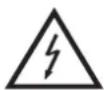
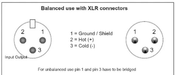
Occupation balanced XLR-connection:
CONNECTION TO THE MAINS
Connect the OMNITRONIC XO-23 only after having made sure that the right voltage (230 V) is available. This device features a T 0.5 A, 250 V fuse.
Connect the device to the mains with the enclosed power supply cable.
The occupation of the connection-cables is as follows:
| Cable Pin International | |
| Brown Live L | |
| Blue Neutral N | |
| Yellow/Green Earth |
The earth has to be connected!
If the device will be directly connected with the local power supply network, a disconnection switch with a minimum opening of 3mm at every pole has to be included in the permanent electrical installation.
The device must only be connected with an electric installation carried out in compliance with the IEC standards. The electric installation must be equipped with a Residual Current Device (RCD) with a maximum fault current of 30mA .
STARTING UP
Make sure to power-up before your power amplifier is turned in order to avoid loud transients which could damage your speakers or annoy your audience.
System test
After connecting all cables, you should carry out a system test. Press all four Mute Buttons in order to mute all outputs.
Activate the HF-outputs first. In case of wrong cabling, HF-signal will come out of bass-speakers that cannot be harmed this way. Vice versa, the LF-signal would destroy your HF-speakers.
Starter's guide to crossovers
With an active crossover, you can separate the output signal of your mixer in different frequency ranges. In this way you can define which signal portion will go to which amplifier.
The Omnitronic crossover can either be run in 2-way stereo or in 3-way mono mode.
Stereo operation is to be used in medium-sized and larger discotheques.
Mono-operation is to be used for larger PAs and requires 2 crossovers.
The crossover is delivered in 2-way stereo mode. If you wish to run the crossover in 3-way mono mode, please press the stereo/mono switch.
OPERATION
Front panel
Channel A and B are identical.
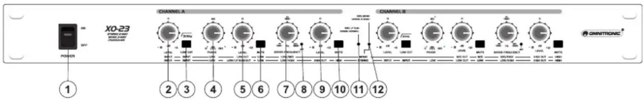
1. POWER Switch
Turns power to the crossover on and off. Be sure to power-up before your power amplifier is turned on to avoid loud transients which could damage your speakers or annoy your audience.
2. INPUT LEVEL Control
To adjust the input level from - to +6 dB.
3. LOW CUT Selector
This switch activates the highpassfilter and allows you to cut down unwanted low frequencies.
With the Low Cut-function, you can attenuate all signals below 30Hz . Please keep this button pressed if you do not need these extremely low frequencies at any rate. If your speaker-system does not support these frequencies, there is danger of speaker damage!
4. PHASE Control
This control reverses the polarity of the Low output.
5. LOW OUTPUT LEVEL Control
Controls the output level of the Low band from - to +12 dB.
6. MUTE Switch
Mutes the Low band.
7. XOVER FREQUENCY Control
This control adjusts the crossover frequency between the respective bands. When the XOVER FREQUENCY switch on the rear unit is pressed, the frequency range is multiplied by the factor 10.
8. XOVER LED
Lights up when the XOVER FREQ switch is active.
9. HIGH OUTPUT LEVEL Control
Controls the output level of the High band from - to +12 dB.
10. MUTE Switch
Mutes the High band.
11. LF LED
This indicator glows red if the Low Sum switch on the rear panel is active.
12. MONO / STEREO LED
This indicator lights red in mono operation and green in stereo operation.
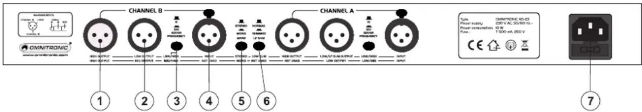
Rear panel
1. HIGH OUTPUT Socket
XLR output for the High Band signal.
2. LOW OUTPUT Sockets
XLR output for the Low Band signal.
3. XOVER FREQUENCY Switch
Switches the control range of the front-panel XOVER FREQ Control from 45 to 950Hz or 450 to 9.5kHz .

Always switch off the entire system before you press this button, as it produces heavy interference noise that could damage your speaker and/or other equipment.
4. INPUT Socket
XLR input signal connector.
5. STEREO/MONO Switch
Switches the unit from stereo to mono.

Always switch off the entire system before you press this button, as it produces heavy interference noise that could damage your speaker and/or other equipment.
6. LOW SUM Switch
In stereo mode, both Low paths can be summed with the Low Sum switch and routed to the Low output of channel A, which is particularly useful in systems using additional subwoofoers.
7. AC-Connection with Fuseholder
Used to plug the power-cord in.
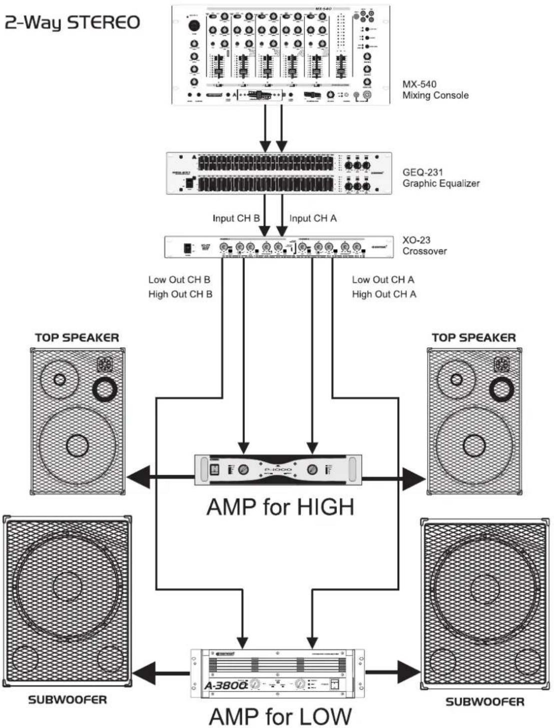
2-way stereo operation
Activate the stereo mode via the MODE switch on the rear panel.
Example for setting the frequency ranges (depending on the system and the room):
Bass Highs
40 Hz - 250 Hz 250 Hz - 20 kHz
The frequency can be adjusted via the LOW/HIGH XOVER Frequency Control, depending on the XOVER Frequency Switch between 45 Hz and 950 Hz or between 450 Hz or 9,5 kHz (LED lit).
With the Input Level Control, you can adjust the incoming signal level from - to +6 dB.
With the Low Level and High Level Controls, you can attenuate the respective output level from - to +12 dB. In the stereo mode, both channels should be adjusted the same way.
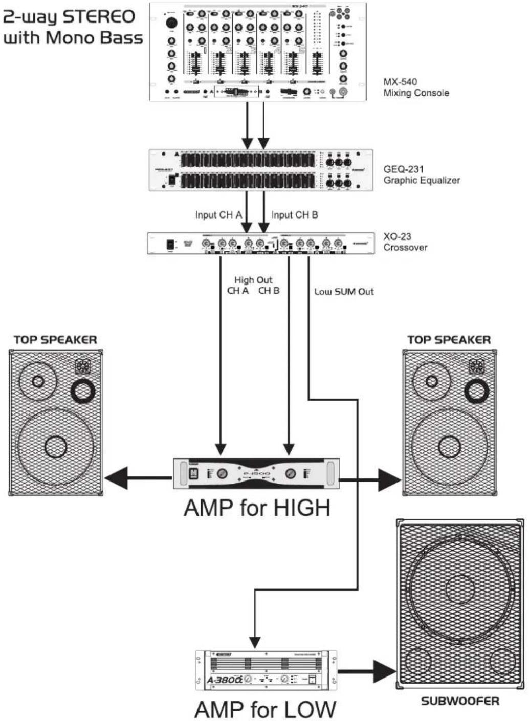
2-way stereo operation with mono-subwoofer
Most common setting in discotheque appliances. Phase erasions in the bass-range can be avoided and the system gains around 3 dB in the bass-range.
Activate the stereo mode via the MODE switch on the rear panel.
Example for setting the frequency ranges (depending on the system and the room):
Bass Highs
40 Hz - 250 Hz 250 Hz - 20 kHz
The frequency can be adjusted via the LOW/HIGH XOVER Frequency Control, depending on the XOVER Frequency Switch between 45 Hz and 950 Hz or between 450 Hz or 9.5 kHz (LED lit).
With the Input Level Control, you can adjust the incoming signal level from - to +6 dB.
With the Low Level and High Level Controls, you can attenuate the respective output level from - to +12 dB. In the stereo mode, both channels should be adjusted the same way.
English
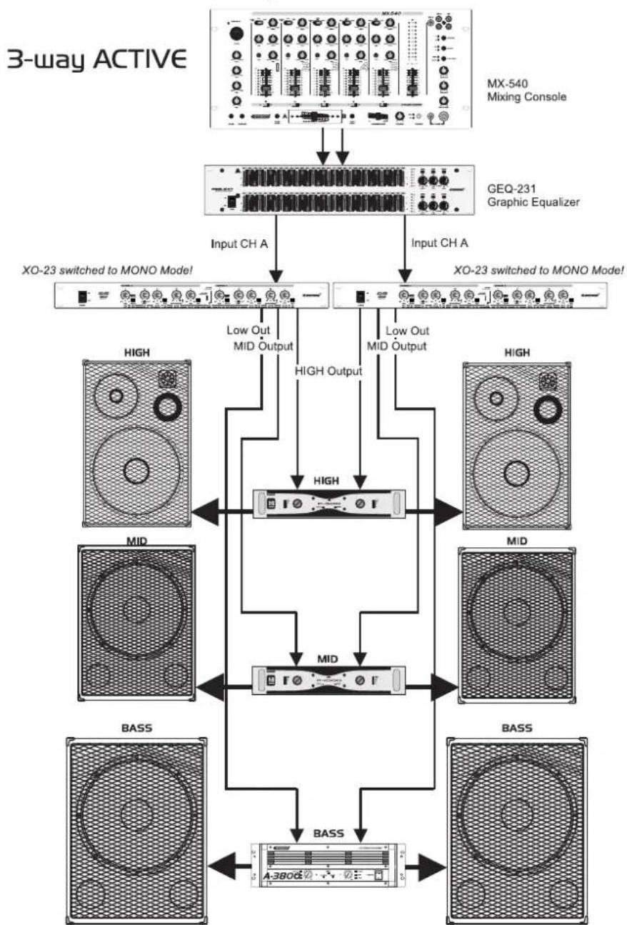
3-way mono operation
Activate the mono mode via the MODE switch on the rear panel.
Please adjust the desired separation frequency between mids and highs via the MID/HIGH XOVER Frequency Control. Make sure that the XOVER Frequency Switch is active. The frequency range ranges from 450 Hz to 9.5 kHz.
The portion of the mids can then be cut via the Mid Level Control.
The portion of the highs can then be cut via the High Level Control.
Example for setting the frequency ranges (depending on the system and the room):
Bass Mids Highs
40-250 Hz 250-6 kHz 6-20 kHz
Please adjust the desired separation frequency between lows and mids via the LOW/MID XOVER Frequency Control. Make sure that the XOVER Frequency Switch is not active. The frequency range ranges from 45 Hz to 950 Hz.
The portion of the bass can then be cut via the Low Output Level Control.
With the Input Control, you can adjust the incoming signal level from - to +6 dB.
With the Low Level and High Level Controls, you can adjust the respective output level from - to +6 dB. For stereo mode two units, which are set identically, are needed.
CLEANING AND MAINTENANCE
DANGER TO LIFE!
Disconnect from mains before starting maintenance operation!
We recommend a frequent cleaning of the device. Please use a soft lint-free and moistened cloth. Never use alcohol or solvents!
There are no servicable parts inside the device except for the fuse. Maintenance and service operations are only to be carried out by authorized dealers.
Replacing the fuse
If the fine-wire fuse of the device fuses, only replace the fuse by a fuse of same type and rating.
Please note: This fuse is being used for both 115V and 230V .
Before replacing the fuse, unplug mains lead.
Procedure:
Step 1: Open the fuseholder on the rear panel with a fitting screwdriver.
Step 2: Remove the old fuse from the fuseholder.
Step 3: Install the new fuse in the fuseholder.
Step 4: Replace the fuseholder in the housing.
Should you need any spare parts, please use genuine parts.
If the power supply cable of this device becomes damaged, it has to be replaced by a special power supply cable available at your dealer.
Should you have further questions, please contact your dealer.
TECHNICAL SPECIFICATIONS
| Power supply: 230 V AC, | 50 Hz ~ |
| Power consumption: 10 W | |
| Fuse: T 0.5 A | |
| Slope: 24 dB / octave | |
| Operation-modes: 2-way-stereo or 3-way-mono | |
| Input: Mono/stereo | |
| Input impedance: 10/20 kOhms (unb./bal.) | |
| Output: Mono/stereo | |
| Output impedance: 300/150 kOhms (unb./bal.) | |
| In/Out connectors: XLR | |
| S/N-ratio: >100 dB | |
| Xover frequency range: 45 Hz - 9 kHz | |
| THD: 0.05% | |
| Crosstalk: | >80 dB, -3 dB |
| Input gain: | -∞ to +6 dB |
| Output gain: | -∞ to +12 dB |
| Low Cut: | 30 Hz |
| Phase adjustment: | 0-180° |
| Dimensions (WxDxH): | 483 x 147 x 46 mm |
| Weight: | 2 kg |
Please note: Every information is subject to change without prior notice. 07.09.2006 ©

OMNITRONIC
X0-23
Occupation balanced XLR-connection:
- MULTI-LANGUAGE-INSTRUCTIONS
- Français
- INTRODUCTION
- Features
- High-quality active stereo crossover
- SAFETY INSTRUCTIONS
- CAUTION!
- Important:
- English
- HEALTH HAZARD!
- OPERATING DETERMINATIONS
- DESCRIPTION
- INSTALLATION
- RACK MOUNTING
- INPUTS
- OUTPUTS
- Occupation balanced XLR-connection:
- CONNECTION TO THE MAINS
- The occupation of the connection-cables is as follows:
- STARTING UP
- System test
- Starter's guide to crossovers
- OPERATION
- Front panel
- POWER Switch
- INPUT LEVEL Control
- LOW CUT Selector
- PHASE Control
- LOW OUTPUT LEVEL Control
- MUTE Switch
- XOVER FREQUENCY Control
- XOVER LED
- HIGH OUTPUT LEVEL Control
- MUTE Switch
- LF LED
- MONO / STEREO LED
- HIGH OUTPUT Socket
- LOW OUTPUT Sockets
- XOVER FREQUENCY Switch
- INPUT Socket
- STEREO/MONO Switch
- LOW SUM Switch
- AC-Connection with Fuseholder
- 2-way stereo operation
- Bass Highs
- 2-way stereo operation with mono-subwoofer
- 3-way mono operation
- Bass Mids Highs
- CLEANING AND MAINTENANCE
- DANGER TO LIFE!
- Replacing the fuse
- Procedure:
- TECHNICAL SPECIFICATIONS
- OMNITRONIC
- X0-23
Brand : Omnitronic
Model : XO23
Category : Mixer