
CCDTR760E - Camcorder SONY - Free user manual and instructions
Find the device manual for free CCDTR760E SONY in PDF.
| Product type | 8 mm camcorder |
| Brand | Sony |
| Model | CCD-TR760E |
| Recording format | 8 mm video cassette (Hi8 compatible) |
| Sensor | CCD (Charge-Coupled Device) |
| Optical zoom | Approximately 12x |
| Focus | Automatic (autofocus) and manual via the underwater housing |
| Viewfinder | Electronic viewfinder (color) |
| Power source | Rechargeable Sony battery (model NP-55 recommended) |
| Dimensions (W x H x D) | Approximately 110 x 110 x 200 mm (without accessories) |
| Weight | Approximately 700 g (without battery or cassette) |
| Main functions | Recording, playback, power zoom, autofocus, adjustable white balance |
| Care and cleaning | Clean with a soft, dry cloth; do not use solvents |
| Safety | Avoid moisture and spray; use only recommended accessories |
| Spare parts | Battery, charger, cables, O-ring (for housing) |
| Repairability | Entrust to an authorized Sony service center |
| Included accessories | A/B/C adapters, mounting plate, O-rings, grease, strap, viewfinder adapter (for housing) |
| General information | Compatible with Marine Pack MPK-TRV2 underwater housing for use down to 75 m |
Frequently Asked Questions - CCDTR760E SONY
User questions about CCDTR760E SONY
0 question about this device. Answer the ones you know or ask your own.
Ask a new question about this device
Download the instructions for your Camcorder in PDF format for free! Find your manual CCDTR760E - SONY and take your electronic device back in hand. On this page are published all the documents necessary for the use of your device. CCDTR760E by SONY.
USER MANUAL CCDTR760E SONY
Operating Instructions
Mode d'emploi
1997 by Sony Corporation
English
Table of contents
Features 2
Supplied accessories....3
Precautions 4
Labeling the parts and controls 5
Position of the adaptor and the remote control cable ..... 6
Notes on the O-ring 8
Attaching the video camera recorder to the marine pack .... 9
Recording....13
When the LEAK lamp flashes 14
Removing the video camera recorder 15
Underwater recording 16
Specifications.... 17
Prerecording checklist....17

This mark indicates that this product is a genuine accessory for Sony video products. When purchasing Sony video products, Sony recommends that you purchase accessories with this "GENUINE VIDEO
ACCESSORIES" mark.
Features
The MPK-TRV2 marine pack allows the following 8 mm video camera recorders to be used underwater.
CCD-TR1*/TR1E*
CCD-TR3*/TR3E*
CCD-TR8*/TR8E*
CCD-TR18E*
CCD-TR330/TR330E
CCD-TR340E
CCD-TR401E
CCD-TR402E
CCD-TR403
CCD-TR410E
CCD-TR420/TR420E
CCD-TR440/TR440E
CCD-TR490/TR490E
CCD-TR501E
CCD-TR502E
CCD-TR503E
CCD-TR506/TR506E
CCD-TR507
CCD-TR510E
CCD-TR520E
CCD-TR555/TR555E
CCD-TR590/TR590E
CCD-TR610E*
CCD-TR620E
CCD-TR710E*
CCD-TR720E
CCD-TR740E
CCD-TR760E*
CCD-TR810E*
CCD-TR820E
CCD-TR825E
CCD-TR910*/TR910E*
CCD-TR920E
CCD-TR1100E
CCD-TR2200*/TR2200E*
CCD-TR2300*/TR2300E*
CCD-TR3000*/TR3000E*
CCD-TR3100E
CCD-TR3300*/TR3300E*
CCD-TR3400E
CCD-TRV10E
CCD-TRV11/TRV11E
CCD-TRV12/TRV12E
CCD-TRV14E
CCD-TRV21/TRV21E
CCD-TRV24E
CCD-TRV30/TRV30E
CCD-TRV31*/TRV31E*
CCD-TRV34
CCD-TRV40/TRV40E
CCD-TRV41*/TRV41E*
CCD-TRV44/TRV44E
CCD-TRV51*/TRV51E*
CCD-TRV54E
CCD-TRV56E
CCD-TRV60E
CCD-TRV61E
CCD-TRV64E
CCD-TRV70/TRV70E
CCD-TRV81E
CCD-TRV91*/TRV91E*
CCD-TRV94/TRV94E
CCD-TRV101/TRV101E
- Recording at a depth of 75 meters (246 feet) is possible.
• The following operations can be performed underwater.
Power on/off
Auto focusing on/off (Only models marked with *)
Recording start/stop
Power zooming
If there are specks or dust in focus on the front glass of the marine pack, move the power zoom lever towards the T (telephoto) side slightly so that the zoom indicator inside the viewfinder moves towards T. (See the illustration below.)

We recommend you use a wide-conversion lens (not supplied) when using the marine pack.
Supplied accessories
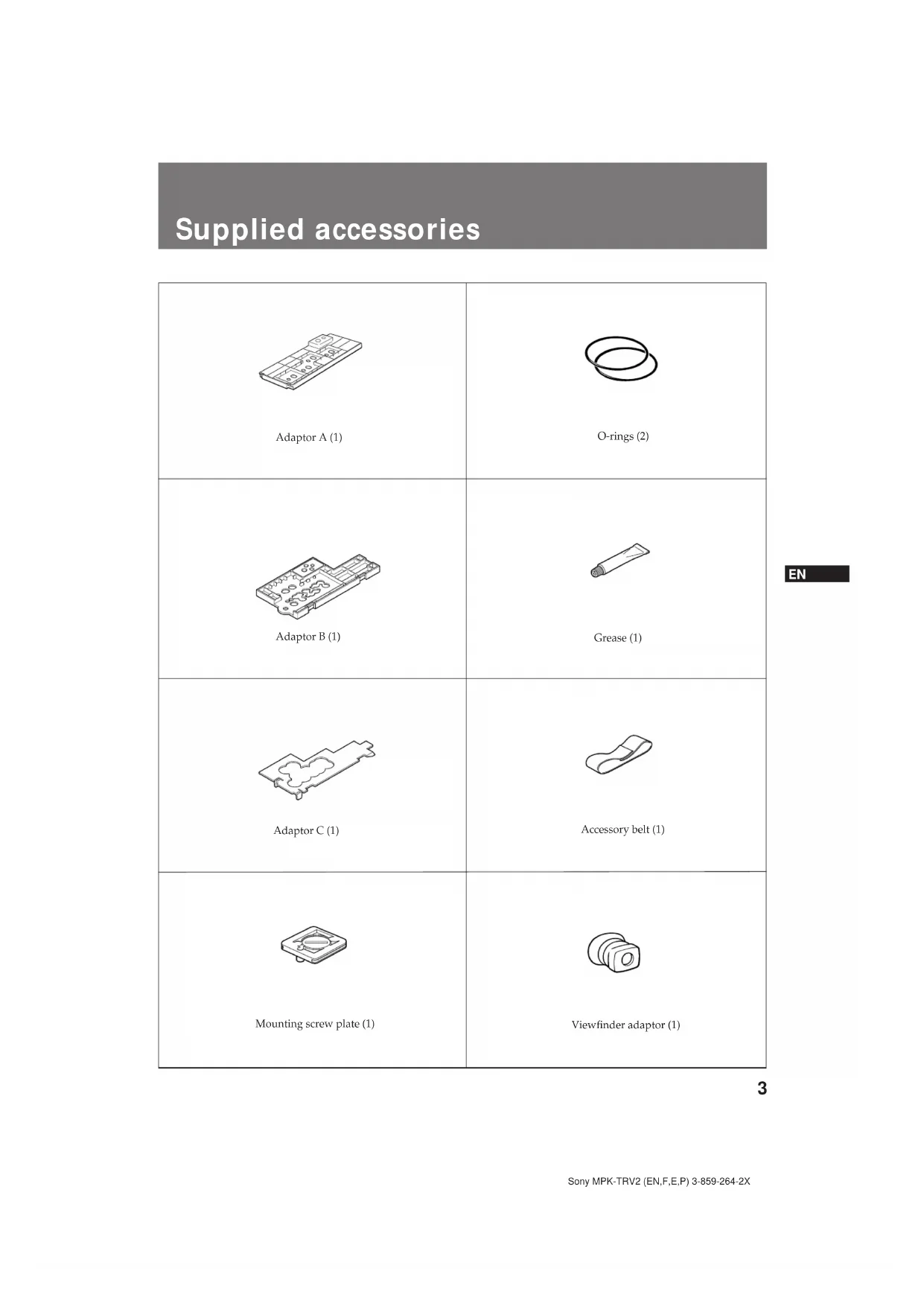
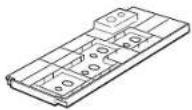 Adaptor A (1) Adaptor A (1) | 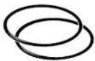 O-rings (2) O-rings (2) |
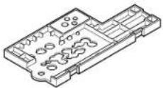 Adaptor B (1) Adaptor B (1) | 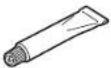 Grease (1) Grease (1) |
 Adaptor C (1) Adaptor C (1) | 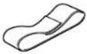 Accessory belt (1) Accessory belt (1) |
 Mounting screw plate (1) Mounting screw plate (1) |  Viewfinder adaptor (1) Viewfinder adaptor (1) |
Precautions
On the video camera recorder
Take care not to expose the equipment to salty air. Do not drip water on the equipment.
- Do not open the marine pack while at sea or at the seaside. Preparations such as installing and checking the equipment should be made in a place with low humidity and no salty air.
- When a video camera recorder is to be used near the sea for a long time, we recommend that it be checked periodically by a Sony dealer.
- If the equipment becomes wet, take it immediately to the nearest Sony dealer for preventive maintenance.
On the video camera recorder power source
We recommend you use battery packs with a large capacity. However, in some cases battery packs NP-99/4500/F930 cannot be attached to the video camera recorder.
On the marine pack
- If you open and join the front and rear shells in a place with high temperature and high humidity, moisture condensation may occur when you put the marine pack in the water, causing the front glass to fog.
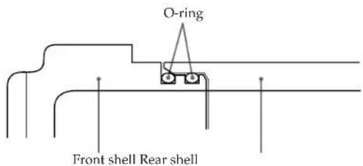
- The waterproof integrity of the marine pack is maintained by the O-ring, and the groove and surface where it touches. Be especially careful not to damage or deform that area.
- Do not leave the marine pack under direct sunlight for a long period of time, otherwise the temperature in the marine pack may rise and the equipment inside may be damaged.
- If you cannot avoid leaving the marine pack under direct sunlight, be sure to cover the marine pack with a towel or other protection.
- Do not throw the marine pack into the water. Lower it gently into the water.
On recording underwater
- Check that the equipment operates correctly and that there is no water leak at a depth of about one meter (3 feet) before you dive deeper.
- Be sure to follow the safety rules for diving, such as diving period and depth.
- Remove the bubbles from the outside of the front glass.
Sony does not accept liability for damage to the video camera recorder, battery, etc. in the marine pack or for the loss of prerecorded material if a water leak caused by incorrect operation occurs.
On maintenance
After recording in the sea, submerge the marine pack with the buckles tightly fastened in fresh water for a while to remove the sea water. Then rinse it with fresh water and dry it with a soft cloth.
- Every time you use the marine pack and the video camera recorder underwater, clean the video camera recorder and the inside of the marine pack with a dry soft cloth. Do not use any type of solvent, such as alcohol or benzine for cleaning, as this may damage the finish.
- When you store the marine pack, grease the O-ring and put it in the groove correctly. Join the front and rear shells then put in a cool place without fastening the buckles. Avoid storing the marine pack in a hot or very cold place, in a place subject to direct sunlight or excessive dust, or together with naphthalene or camphor as. This will damage the marine pack.
- If water comes between the rear shell and the rubber part, remove the rubber and clean it with a dry soft cloth.
On transportation
- When transporting the marine pack, be sure to remove the video camera recorder from the marine pack.
- When transporting the marine pack by air or by car, use a marine pack carrying case (not supplied).
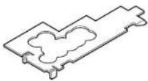
Labeling the parts and controls
- For the use of each part or control, see the pages indicated in parenthesis.
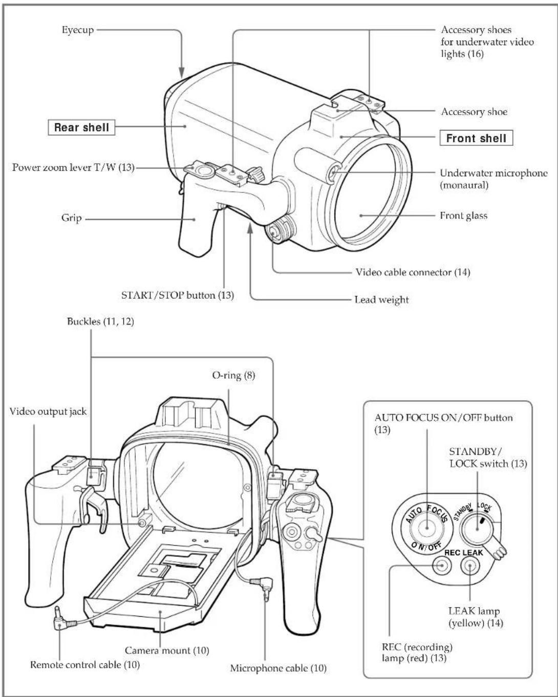
Position of the adaptor and the remote control cable
The position of the adaptor and the mounting screw plate depend on the video camera model. See the following page when adjusting the adaptor and mounting screw plate position.
Check the position for the video camera recorder you use. Mounting instructions are explained in "Attaching the video camera recorder to the marine pack" on page 9.
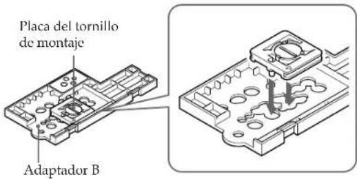
Position of the mounting screw plate on the adaptor
Put the mounting screw plate on the number of the adaptor depending upon the model of video camera recorder.
Adaptor A
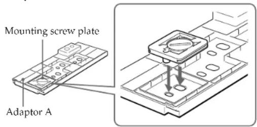
To disassemble after using.
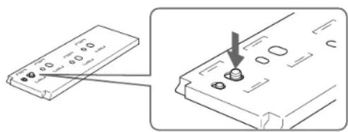
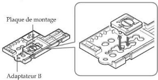
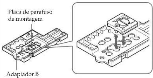
Adaptor B
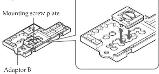
Attach adaptor C to adaptor B.
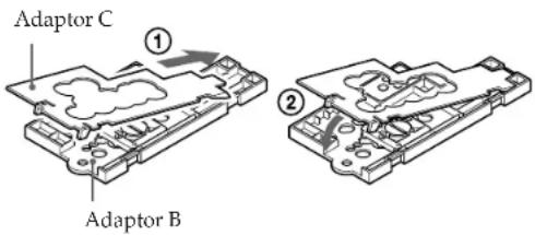
To detach adaptor C from adaptor B.
| Video camera recorder CCD- | Position of the mounting screw plate on the adaptor | Video camera recorder CCD- | Position of the mounting screw plate on the adaptor | ||
| Without a wide-conversion lens | With a wide-conversion lens | Without a wide-conversion lens | With a wide-conversion lens | ||
| TRV30/TRV40/TRV70TRV30E/TRV40E/TRV60E/TRV70E | A1 | A2 | TR1/TR3/TR8TR1E/TR3E/TR8E/TR18E | B1 | B3 |
| TR330/TR403/TR420/TR440/TR490/TR590TR330E/TR340E/TR401E/TR402E/TR410E/TR420E/TR440E/TR490E/TR510E/TR520E/TR590E | A3 | TR506/TR507/TR501E/TR502E/TR503E/TR506E/TR620E/TR720E/TR740E TRV11/TRV12/TRV21/TRV34/TRV44/TRV10E/TRV11E/TRV12E/TRV14E/TRV21E/TRV24E/TRV44E | B2 | B5 | |
| TRV94/TRV54E/TRV56E/TRV94E | B2 B9 | ||||
| TR3000/TR3000E | B3 B6 | ||||
| TR555/TR555E | B3 B7 | ||||
| TRV101/TRV101E | B3 | — | |||
| TR910/TR610E/TR710E/TR760E/TR810E/TR910E | B4 B6 | ||||
| TR2200/TR2300/TR3300/TR2200E/TR2300E/TR3100E/TR3300E/TR3400E/TRV31/TRV41/TRV51/TRV91/TRV31E/TRV41E/TRV51E/TRV61E/TRV81E/TRV91E | B4 B7 | ||||
| TRV64E/TRV820E/TRV825E/TRV920E | B5 B8 | ||||
| TR1100E | B5 B9 | ||||
A, B adaptor to be used.
1, 2, 3... corresponding number on the adaptor.
Notes
• The CCD-TRV101/TRV101E video camera recorders cannot be fitted with a wide conversion lens.
- When you attach a wide conversion lens to the CCD-TR820E/TR825E/TR1100E/TR2200/TR2200E/TR3100E/TRV10E/TRV11/TRV11E/TRV12/TRV12E/TRV21/TRV21E/TRV31/TRV31E/TRV41/TRV41E/TRV51/TRV51E/TRV61E/TRV81E/TRV91/TRV91E video camera recorders, you cannot attach the viewfinder adaptor.
- When you attach a wide conversion lens to the CCD-TRV10E/TRV11/TRV11E/TRV12/TRV12E/TRV21/TRV21E video camera recorders, you cannot attach Sony battery NP-99/4500.
- When you attach a wide conversion lens to the CCD-TR1100E/TR2200/TR2200E/TR2300/TR2300E/TR3100E/TR3300/TR3300E/TR3400E video camera recorders, you cannot attach Sony battery NP-F930.
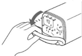
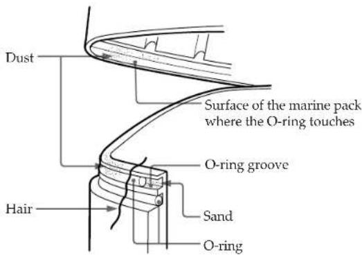
Notes on the O-ring
The O-ring assures the waterproof function of the marine pack. To maintain waterproof integrity, use it correctly. Incorrect handling may cause water to leak in.
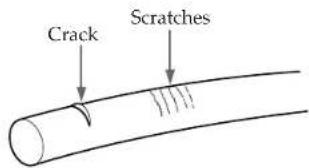
Check that there are no scratches or cracks.
Scratches or cracks on the O-ring may cause water to leak in. If the O-ring is damaged in this way, replace it with a new one. Do not remove the O-ring from the groove with a metal tool or a tool with a sharp point.
Remove any dust, sand or hair from the O-ring.
Make sure there is no dust, sand or hair on the O-ring, in the groove, or on the surface of the marine pack where the O-ring touches. If there is, clean it completely, or the O-ring and the surface of the marine pack may be damaged and water may leak in.
Grease the O-ring
The grease protects the O-ring from wear.
Check that there are no cracks or dust on the O-ring, then grease it using your finger. While greasing, double check that there are no cracks or dust.
Never use cloth or paper to apply grease because the fibers may cling.
Do not use any type of grease other than the supplied one, or it may damage the O-ring.
If you run out of silicone grease (2-115-921-01) you can purchase it from your nearest Sony Service Center.
Do not twist the O-ring.
Put the O-ring in the groove evenly. Never twist it.

Do not pinch the O-ring with the marine pack.
When joining the front and rear shells, take care not to pinch the O-ring between them shells. If this happens, not only will the O-ring be damaged, but water may leak in.
Storage
Put the supplied spare O-rings in the original carton and store it in a cool place.
- Do not expose the O-ring to direct sunlight.
- Do not place a heavy object on the O-ring.
- Do not fold the O-ring.
Useful life of the O-ring.
Depending upon maintenance and the length of use, we recommend changing the O-ring every one or two years. The O-ring (3-952-928-01) can be replaced at your nearest Sony Service Center.
Attaching the video camera recorder to the marine pack
| 1 Remove the lens cap, shoulder strap, filter, etc., from the video camera recorder. | 2 Attach a charged battery pack and insert a video cassette. | |
3 Attach the wide conversion lens (not supplied). By attaching the wide conversion lens, the shooting coverage becomes wider, and the subject size becomes smaller.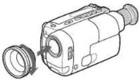 | 4 Attach the Viewfinder adaptor.If the viewfinder adaptor is loose when it is attached, bend the eyecup of the camcorder and attach it again.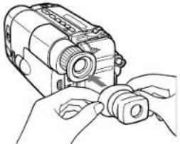 | |
5 When using adaptor A, attach it to the video camera recorder.Check that the position of the mounting screw plate is correct. (See pages 6 arWhen using adaptor B, s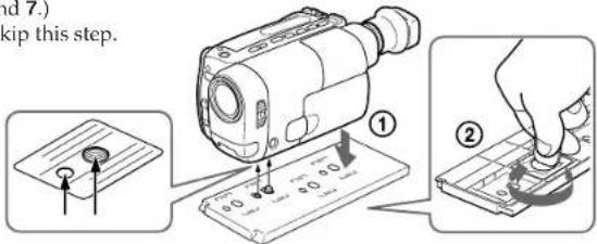 | ||
6 Adjust the video camera recorder.Refer to the operation manual of your video camera recorder.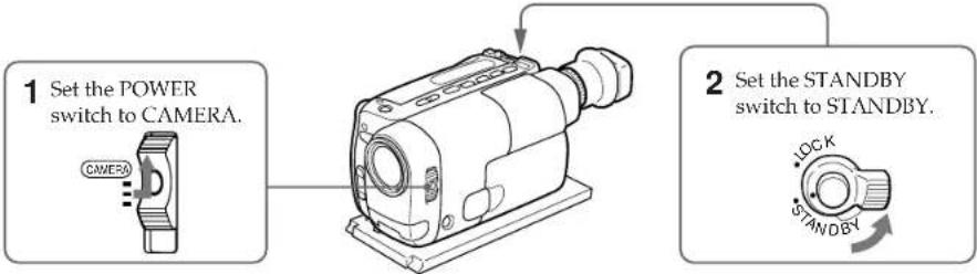 The following adjustments are needed when your video camera recorder has the corresponding function.Refer to the operation manual of the video camera recorder for details. The following adjustments are needed when your video camera recorder has the corresponding function.Refer to the operation manual of the video camera recorder for details. | ||
| White balance | Normally set to (outdoor).Set to (indoor) for night diving. | On some video camera recorder models, you cannot adjust the focus with the button on the marine pack.Set the focus to auto focus mode (see page 2). |
| Shutter speed | Set where no indicator appears. | |
| Program AE | Set where no indicator appears. | |
| Brightness | Turn off the indicator. | |
| White balance | Normally set to ⚙ (outdoor).Set to ⚙ (indoor) for night diving. |
| Shutter speed | Set where no indicator appears. |
| Program AE | Set where no indicator appears. |
| Brightness | Turn off the indicator. |
(continued)
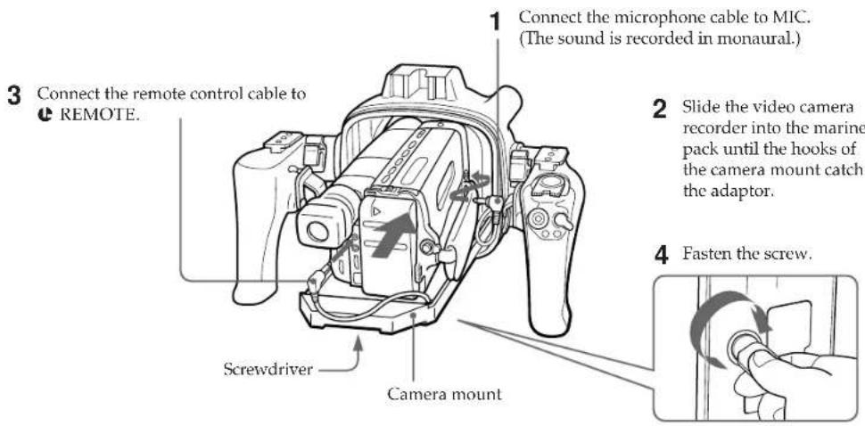
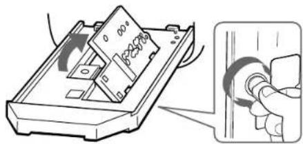
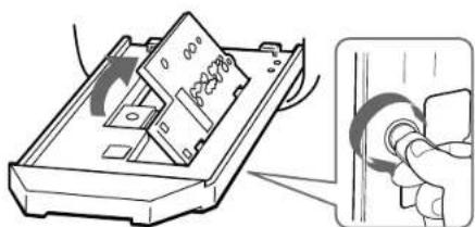
7 Attach the video camera recorder to the marine pack.
Check the position of the adaptor. (See pages 6 and 7.)
When using adaptor A
When using adaptor B
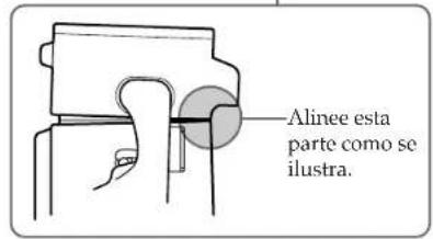
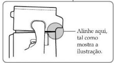
1 Align the right side of the adaptor with the hooks of the camera mount, then push down the adaptor.
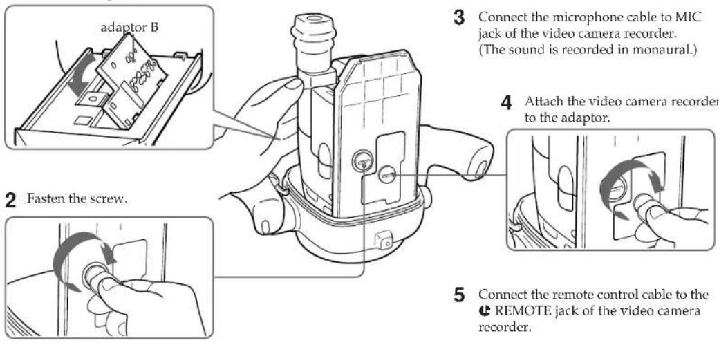
3 Connect the microphone cable to MIC jack of the video camera recorder. (The sound is recorded in monaural.)
4 Attach the video camera recorder to the adaptor.
5 Connect the remote control cable to the ⬆ REMOTE jack of the video camera recorder.
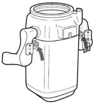
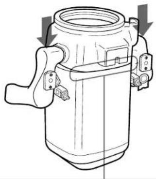
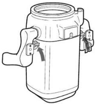
8 Raise the buckles until they stop.
Check the O-ring and grease it slightly.
9 Fasten the video camera recorder with the accessory belt.
When you fasten the video camera recorder with accessory belt, take care not to touch the zoom button.
(continued)
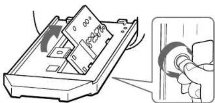
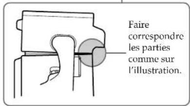
10 Attach the front shell to the rear shell.
1 Put the front shell on the rear shell.
2 Press the top of both grips firmly.
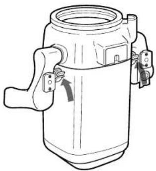
3 Lower both buckles at the same time until they are locked. You will hear a click.
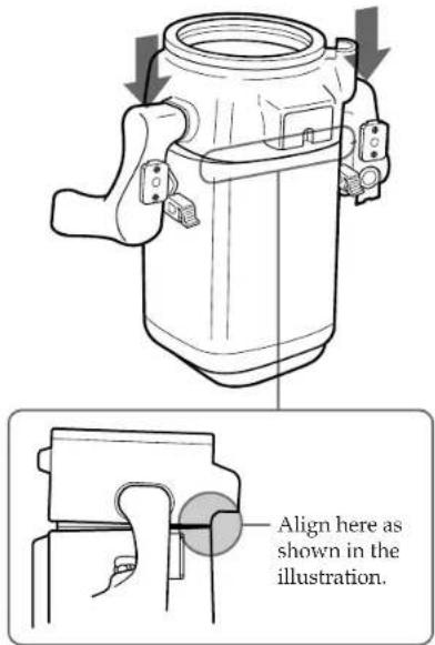
Now you are ready for underwater recording.
Set the STANDBY/LOCK switch of the marine pack to LOCK.
If you set it to STANDBY, the battery may be used up before recording.
Note
When the viewfinder adaptor is attached to the viewfinder of your camcorder, you get a wide view of what appears in the viewfinder screen. However, when viewed from an angle, the screen may appear distorted.
Recording
Check that the equipment operates correctly and that there is no water leak at a depth of about one meter (3 feet) before you dive deeper.
1 Set the STANDBY/LOCK switch to STANDBY.
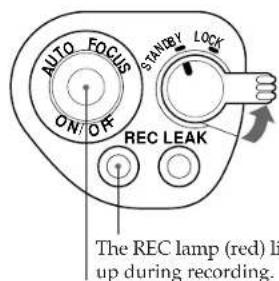
AUTO FOCUS ON/OFF button
Power zoom lever
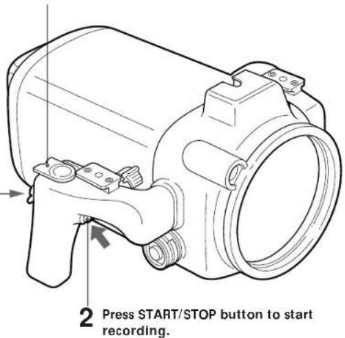
To zoom
Slide the power zoom lever towards T for telephoto (subject appears closer) or W for wide-angle (subject appears farther away). The zooming speed can be changed on some video camera recorder models from a slow speed to faster by sliding the zooming lever a little more.
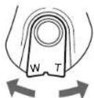
Wide-angle Telephoto
When you set the power zoom lever to the full wide-angle position (macro), specks or bubbles on the front glass may come into focus. In this case, slide the power zoom lever a little towards T and return towards W.
To keep a subject in focus
After you focus on a subject, press the AUTO FOCUS ON/OFF button to set the video camera recorder to manual focus mode.
Even if fish swim between the video camera recorder and the subject, you can still keep the subject in focus.
Note
On some video camera recorder models, the AUTO FOCUS ON/OFF button is not operative.
Set the video camera recorder to auto focus mode (see page 2).
To stop recording
Press the START/STOP button.
(continued)
To attach/detach the lid of the video cable connector
A video cable connector is provided so that video equipment can be connected to the marine pack in the future.
When you reattach the lid, grease the O-ring of the lid before inserting it into the connector.
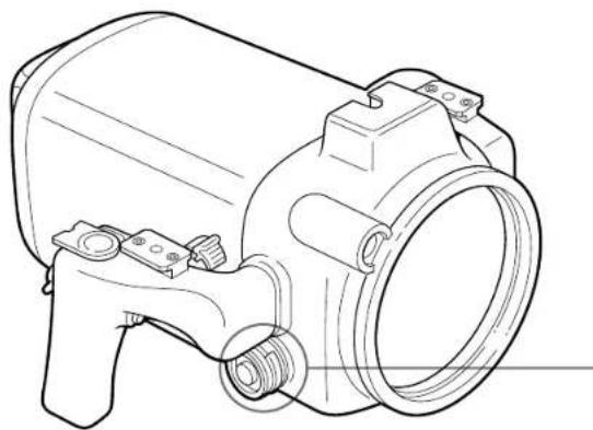
To detach To attach

2 pull out.
1 While pressing here,
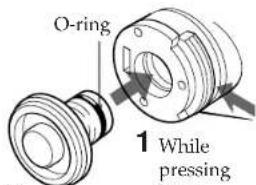
2 press in.
Note
Do not remove the lid underwater.
When the LEAK lamp flashes
If water happens to leak in, the LEAK lamp (yellow) flashes.
In such a case, remove the marine pack from the water as soon as possible, keeping it horizontal. Be sure to surface following the safety rules for diving.
Dry the marine pack with a soft cloth and then open it. To switch off the lamp, disconnect the remote control cable.
Check the cause of the leak.
If the video camera recorder is wet, take it to the nearest Sony dealer immediately.
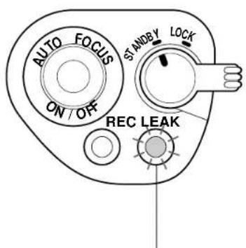
LEAK lamp (yellow)
Removing the video camera recorder
Before opening the marine pack, rinse it with fresh water and dry with a soft cloth.
Note
When you open the marine pack, follow this procedure to prevent the video camera recorder from getting wet.
• Dry the marine pack well.
- Wipe off any water between the front and rear shells with a towel.
- Make sure you are dry. Take care that no water drips from your wet suit.
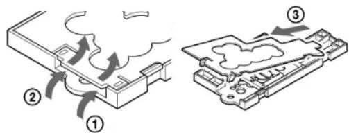
1 Remove the accessories.
2 Open the marine pack.
1 Before opening the marine pack, rinse it with fresh water and dry with a soft cloth.
2 Unfasten both buckles and remove the front shell.
4 Insert the remote control plug and the microphone plug where they were.
3 Take the video camera recorder out of the front shell.
1 Disconnect the remote control cable.
4 Disconnect the microphone
5 Remove the adaptor.
Adaptor A
Adaptor B
Underwater recording
Recording underwater is different from recording on land because it is affected by the clarity, depth of the water and the light conditions. The following are hints for good recording underwater.
Color characteristics underwater
Water absorbs light, especially red light, so that objects in deep water are seen as bluish. The color of objects is affected by the clarity of the water.
Best time for recording
The best recording time is from 10:00 a.m. to 2:00 p.m. When the sun its highest, optimum results can be obtained.
Subject size underwater
Since the refractive index underwater is higher than that in air, an object appears 1/4 more closer, and therefore larger. This phenomenon affects the lens on the video camera recorder as well as the human eye. Using a wide-conversion lens (not supplied) is recommended.
Camera work In slow and stable motion
When recording, keep your body stable. An unstable shot will be magnified on the TV screen. Move the video camera recording as slowly as possible. As most of the object underwater move, you can record a good programme without moving the video camera recorder.
Underwater video light
In deep water or under rocks where direct sunlight does not reach, recording with an underwater video light is recommended.
To record at night, use a powerful underwater video light.
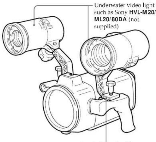
Attachable to the left and right shoes
Specifications
Compatible video camera recorder
See page 2.
Material Aluminum alloy, glass, plastic, lead
Waterproofing O-ring, 2 buckles
Usable depth Up to 75 meters (246 feet)
Underwater microphone
Condenser microphone (monaural)
Controllable function
Power on/off, recording start/stop, auto
focus on/off, power zooming
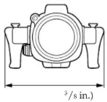
Dimensions
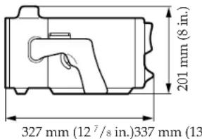
Mass Approx. 8 kg (17 lb 10 oz)
Supplied accessories
Adaptor A (1)/B (1)/C (1)
Mounting screw plate (1)
O-rings (2)
Grease (1)
Accessory belt (1)
Viewfinder adaptor (1)
Recommended accessories
Underwater video light HVL-M20, HVL-
ML20, HVL-80DA
Carrying case LCH-M40
Design and specifications are subject to change without notice.
Prerecording checklist
To make sure that you do not miss shooting opportunities, go over the following checklist.
| Item | Checkpoints |
| Battery pack | • Fully charged. |
| Video cassette | • A cassette is inserted.• Tape length will cover the planned recording time.• The tape is wound to the point where recording is to begin.• The safety tab on the cassette is in the correct position. (The window is not red.) |
| Microphone cable, remote control cable | • Firmly connected to the respective jacks of the video camera recorder (p. 10). |
| Video camera recorder | • Set POWER to CAMERA (p. 9).• Set STANDBY/LOCK to STANDBY (p. 9). |
| O-ring | • No scratches or cracks.• No dust, sand or hair around it.• Correctly set in the groove (p. 8). |
| Buckles | • Correctly fastened (p. 12). |
Français
Tables des matières
Caractéristiques 2
Accessoires fournis 3
Précautions 4
Nomenclature....5
Transport
Adaptateur B
| Camescope CCD- | Position de la plaque de montage sur l'adaptateur | Camescope CCD- | Position de la plaque de montage sur l'adaptateur | ||
| Sans convertisseur grand angle | Avec convertisseur grand angle | Sans convertisseur grand angle | Avec convertisseur grand angle | ||
| TRV30/TRV40/TRV70TRV30E/TRV40E/TRV60E/TRV70E | A1 | A2 | TR1/TR3/TR8TR1E/TR3E/TR8E/TR18E | B1 | B3 |
| TR330/TR403/TR420/TR440/TR490/TR590TR330E/TR340E/TR401E/TR402E/TR410E/TR420E/TR440E/TR490E/TR510E/TR520E/TR590E | A3 | TR506/TR507/TR501E/TR502E/TR503E/TR506E/TR620E/TR720E/TR740E TRV11/TRV12/TRV21/TRV34/TRV44/TRV10E/TRV11E/TRV12E/TRV14E/TRV21E/TRV24E/TRV44E | B2 | B5 | |
| TRV94/TRV54E/TRV56E/TRV94E | B2 B9 | ||||
| TR3000/TR3000E | B3 B6 | ||||
| TR555/TR555E | B3 B7 | ||||
| TRV101/TRV101E | B3 | — | |||
| TR910/TR610E/TR710E/TR760E/TR810E/TR910E | B4 B6 | ||||
| TR2200/TR2300/TR3300/TR2200E/TR2300E/TR3100E/TR3300E/TR3400E/TRV31/TRV41/TRV51/TRV91/TRV31E/TRV41E/TRV51E/TRV61E/TRV81E/TRV91E | B4 B7 | ||||
| TRV64E/TRV820E/TRV825E/TRV920E | B5 B8 | ||||
| TR1100E | B5 B9 | ||||
Retrait
Adaptateur B
Sobre el transporte
Adaptador B
| Videocámara CCD- | Posición de la placa del tornillo de montaje en el adaptador | Videocámara CCD- | Posición de la placa del tornillo de montaje en el adaptador | ||
| Sin un objetivo de conversión panorámica | Con un objetivo de conversión panorámica | Sin un objetivo de conversión panorámica | Con un objetivo de conversión panorámica | ||
| TRV30/TRV40/TRV70TRV30E/TRV40E/TRV60E/TRV70E | A1 | A2 | TR1/TR3/TR8TR1E/TR3E/TR8E/TR18E | B1 | B3 |
| TR330/TR403/TR420/TR440/TR490/TR590TR330E/TR340E/TR401E/TR402E/TR410E/TR420E/TR440E/TR490E/TR510E/TR520E/TR590E | A3 | TR506/TR507/TR501E/TR502E/TR503E/TR506E/TR620E/TR720E/TR740E TRV11/TRV12/TRV21/TRV34/TRV44/TRV10E/TRV11E/TRV12E/TRV14E/TRV21E/TRV24E/TRV44E | B2 | B5 | |
| TRV94/TRV54E/TRV56E/TRV94E | B2 B9 | ||||
| TR3000/TR3000E | B3 B6 | ||||
| TR555/TR555E | B3 B7 | ||||
| TRV101/TRV101E | B3 | — | |||
| TR910/TR610E/TR710E/TR760E/TR810E/TR910E | B4 B6 | ||||
| TR2200/TR2300/TR3300/TR2200E/TR2300E/TR3100E/TR3300E/TR3400E/TRV31/TRV41/TRV51/TRV91/TRV31E/TRV41E/TRV51E/TRV61E/TRV81E/TRV91E | B4 B7 | ||||
| TRV64E/TRV820E/TRV825E/TRV920E | B5 B8 | ||||
| TR1100E | B5 B9 | ||||
Para quitar
Adaptador B
Acerca do transporte
Adaptador B

2 Ajuste o interruptor STANDBY a STANDBY.

(Continua)

Para desacoplar
Adaptador B

- ENGLISH
- TABLE OF CONTENTS
- FEATURES
- SUPPLIED ACCESSORIES
- PRECAUTIONS
- ON THE VIDEO CAMERA RECORDER
- ON THE VIDEO CAMERA RECORDER POWER SOURCE
- ON THE MARINE PACK
- ON RECORDING UNDERWATER
- ON MAINTENANCE
- ON TRANSPORTATION
- LABELING THE PARTS AND CONTROLS
- POSITION OF THE ADAPTOR AND THE REMOTE CONTROL CABLE
- POSITION OF THE MOUNTING SCREW PLATE ON THE ADAPTOR
- NOTES
- NOTES ON THE O-RING
- GREASE THE O-RING
- DO NOT TWIST THE O-RING
- STORAGE
- USEFUL LIFE OF THE O-RING
- ATTACHING THE VIDEO CAMERA RECORDER TO THE MARINE PACK
- 7 ATTACH THE VIDEO CAMERA RECORDER TO THE MARINE PACK
- WHEN USING ADAPTOR B
- 9 FASTEN THE VIDEO CAMERA RECORDER WITH THE ACCESSORY BELT
- 10 ATTACH THE FRONT SHELL TO THE REAR SHELL
- NOW YOU ARE READY FOR UNDERWATER RECORDING
- NOTE
- RECORDING
- TO ZOOM
- TO KEEP A SUBJECT IN FOCUS
- TO STOP RECORDING
- TO ATTACH/DETACH THE LID OF THE VIDEO CABLE CONNECTOR
- WHEN THE LEAK LAMP FLASHES
- REMOVING THE VIDEO CAMERA RECORDER
- 1 REMOVE THE ACCESSORIES
- 2 OPEN THE MARINE PACK
- 4 INSERT THE REMOTE CONTROL PLUG AND THE MICROPHONE PLUG WHERE THEY WERE
- 3 TAKE THE VIDEO CAMERA RECORDER OUT OF THE FRONT SHELL
- 5 REMOVE THE ADAPTOR
- UNDERWATER RECORDING
- COLOR CHARACTERISTICS UNDERWATER
- BEST TIME FOR RECORDING
- SUBJECT SIZE UNDERWATER
- CAMERA WORK IN SLOW AND STABLE MOTION
- UNDERWATER VIDEO LIGHT
- SPECIFICATIONS
- PRERECORDING CHECKLIST
- FRANÇAIS
- TABLES DES MATIÈRES
- TRANSPORT
- SOBRE EL TRANSPORTE
- ACERCA DO TRANSPORTE
Brand : SONY
Model : CCDTR760E
Category : Camcorder