
DynaGATE 10-14 - IoT gateway Eurotech - Free user manual and instructions
Find the device manual for free DynaGATE 10-14 Eurotech in PDF.


User questions about DynaGATE 10-14 Eurotech
0 question about this device. Answer the ones you know or ask your own.
Ask a new question about this device
Download the instructions for your IoT gateway in PDF format for free! Find your manual DynaGATE 10-14 - Eurotech and take your electronic device back in hand. On this page are published all the documents necessary for the use of your device. DynaGATE 10-14 by Eurotech.
USER MANUAL DynaGATE 10-14 Eurotech
Multi-service IoT Gateway
ITxPT, AI Accelerated, LTE 5G Ready
EN
Hardware Manual
Original instructions
Document code: DYGATE-10-14_HWM_EN_0-8
Document revision: 0-8 (2023.06.15)
Intended audience of this document
This document is intended for system integrators. System integrator is a term applied to skilled persons who are specialized in linking together, physically or functionally, different computing systems and software applications to operate as a coordinated whole in compliance with the applicable regulations.
Skilled person is a term applied to persons who have training or experience in the equipment technology, particularly in knowing the various energies and energy magnitudes used in the equipment. Skilled persons are expected to use their training and experience to recognize energy sources capable of causing pain or injury and to take action for protection from injury from those energies. Skilled persons should also be protected against unintentional contact or exposure to energy sources capable of causing injury.
How to get technical support
To get technical support, refer to: https://www.eurotech.com/support
The following resources are available:
- Support Portal: https://support.eurotech.com
- Download Area: https://www.eurotech.com/download
RMA (Return Merchandise Authorization): https://www.eurotech.com/support/rma
Trademarks
All trademarks, registered trademarks, logos, trade names, products names contained in this document are the property of their respective owners.
Revision history
| Revision | Description | Date of Issue |
| 0-8 | Preliminary release for certification | 2023.06.15 |
To get started with the DynaGATE 10-14:
1. Obey the instructions and warnings contained in this Hardware Manual
To lower the risk of personal injury, electric shock, fire, or damage to the equipment, obey the instructions and warnings contained in this manual.
For more information, refer to: "Safety-related information" on page 7.
If you have questions about these instructions, refer to: https://www.eurotech.com/support.
2. Know the DynaGATE 10-14 and its interfaces
For more information, refer to:
"Product overview" on page 16
- "Technical specifications" on page 19
"Interfaces overview" on page 31
3. Install the DynaGATE 10-14
For more information, refer to:
- "Mechanical specifications" on page 68
- "Product installation" on page 70^
4. Supply power to the DynaGATE 10-14
For more information, refer to: "Product power requirements" on page 72
5. For more information
For more information, refer to: "DynaGATE 10-14 EL Software Manual".
CONTENTS
Intended audience of this document 2
How to get technical support 2
Trademarks 2
Revision history 2
Getting started 3
Contents 4
1 Safety-related information 7
1.1 Important information 8
1.2 Explanation of messages 8
1.3 Safety instructions 9
1.3.1 Power supply safety instructions 9
1.3.2 Wireless safety instructions 9
1.3.3 Product handling safety instructions: product's surfaces may be hot 9
3 Technical terms and graphical symbols 14
3.1 Technical terms (acronyms, abbreviations) 15
3.2 Graphical symbols 15
4 Product overview 16
4.1 Product description 17
4.2 Intended use and not allowed uses of the product 18
4.2.1 Deterministic output notice 18
4.2.2 Intended use 18
4.2.3 Not allowed uses 18
4.3 Technical specifications 19
4.4 Product label 21
4.5 Optional accessories 21
5 Certifications 22
5.1 CE marking 23
5.1.1 Safety 23
5.1.2 RoHS 3 compliance 23
5.1.3 Packaging and packaging waste 23
5.1.4 Product disposal and recycling 23
5.1.5 RED compliance (all product variants but: -x1) 24
5.2 REACH compliance 24
5.3 UKCA marking 24
5.4 FCC compliance 25
5.4.1 FCC marking 25
5.4.2 FCC compliance: Class B Digital Device 25
5.4.3 RF radiation exposure statement 26
5.4.4 FCC restrictions on 5 GHz Wi-Fi usage 26
5.4.5 FCC labeling information 26
5.5 ISED Canada compliance 27
5.5.1 ISED compliance: Class B Digital Device 27
5.5.2 RF radiation exposure statement 27
5.5.3 ISED restrictions on 5 GHz Wi-Fi usage 28
5.5.4 ISED labeling information 28
5.5.5 Responsible parties: Canadian Representative contact information 28
5.6 MIC Japan 29
5.7 Antennas list 30
5.7.1 Notice for EU 30
5.7.2 Notice for UK 30
5.7.3 Notice for US 30
5.7.4 Notice for Canada/Avis pour le Canada 30
6 Interfaces overview 31
6.1 Front side interfaces overview 32
6.2 LED indicators overview 33
6.3 Service Panel overview 34
6.3.1 How to remove the Service Panel cover 34
6.3.2 Service Interfaces overview 35
6.3.3 MicroSD and MicroSIM card connectors 36
6.3.4 Reset button 36
6.3.5 USB Serial Console 37
6.3.6 DIP switch definitions 38
6.3.7 User-programmable button: factory restore 39
6.4 Rear side interfaces overview 40
7 Front interfaces in detail 42
7.1 CAM (Camera IN) connector (only for product variant: -x5) 43
7.1.1 CAM connector specifications 43
7.2 HDMI connector 44
7.2.1 HDMI connector specifications 44
7.3 USB connectors 45
7.3.1 USB 0 and USB 1 connectors specifications 45
7.4 Audio connector (AUD) 46
7.4.1 Audio specifications 46
7.4.2 Audio connector specifications 46
7.4.3 99ACC-70000-A0001: Audio ITxPT cable 47
7.5 PWR (Power IN) connector 48
7.5.1 99ACC-70000-A0004: Power ITxPT cable 48
7.6 Earth connection terminal 49
8 Rear interfaces in detail 50
8.1 I/O (Digital I/Os and Analog INs) connector 51
8.1.1 I/O specifications 51
8.1.2 I/O connector specifications 52
8.1.3 99ACC-70000-A0002: Auxiliary (I/O) ITxPT cable 53
8.2 COM connectors 54
8.2.1 Termination resistors and fail-safe receivers 54
8.2.2 COM0 and COM1 connectors specifications (for all product variants) 55
8.2.3 COM2 and COM3 connectors specifications (only for product variants -x9) 56
8.3 Ethernet connectors 57
8.3.1 Ethernet specifications 57
8.3.2 Ethernet connectors specifications 57
8.4 CAN connectors 58
8.4.1 Termination resistors 58
8.4.2 CAN0 and CAN1 connectors specifications 58
8.4.3 99ACC-70000-A0003: CAN ITxPT cable 59
8.5 GNSS 60
8.5.1 GNSS specifications (product variants -x1, -x3, -x5, -x7, -x9) 60
8.5.2 GNSS specifications (product variants -x4) 60
8.5.3 GNSS antenna - Installation guidelines 60
8.5.4 GNSS antenna connector specifications 61
8.6 Wi-Fi and Bluetooth (all product variants but: -x1) 62
8.6.1 Wi-Fi and Bluetooth specifications 62
8.6.2 Wi-Fi/Bluetooth antenna - Installation guidelines 62
8.6.3 Wi-Fi/Bluetooth antenna connector specifications 63
8.7 Cellular Modem (all product variants but: -x1) 64
8.7.1 Cellular Modem specifications 64
8.7.2 Cellular Modem antennas - Installation guidelines 64
8.7.3 Cellular Modem antennas connectors specifications 65
9 Other interfaces in detail 66
9.1 TPM 67
9.2 Watchdog 67
9.3 RTC and tamper detection 67
9.3.1 The RTC Devices 67
9.3.2 The RTC backup supercap 67
9.3.3 The tamper detection 67
10 Mechanical specifications 68
10.1 Product enclosure specifications 69
10.2 Product mechanical dimensions 69
11 Product installation 70
11.1 Introduction 71
11.2 How to install the product 71
12 Product power requirements 72
12.1 Important note 73
12.2 Power specifications 73
12.3 Power IN connector specifications 73
12.4 How to supply power and turn ON the product 74
12.4.1 Power supply safety instructions 74
12.4.2 How to supply power and turn ON the product 75
12.5 Supercap-based power backup feature 76
12.6Turning OFF the product 76
12.7 Reducing the power consumption of the product 76
12.8 How to reset the product 76
12.8.1 Hardware reset 76
12.8.2 Software reset 76
13 Product maintenance 77
13.1 How to maintain the product 78
Notes 79
1 SAFETY-RELATED INFORMATION
This chapter gives the following information:
1.1 Important information 8
1.2 Explanation of messages 8
1.3 Safety instructions 9
1.1 Important information
For safe and proper use, obey these instructions. Keep them for future reference.
Failure to obey these instructions, violates the standards of safety, design, manufacture, and intended use of the product.
Eurotech assume no liability for damages caused by failure to obey these instructions.
If you have questions about these instructions, refer to: https://www.eurotech.com/support.
Additional safety-related information is given in the following chapters.
1.2 Explanation of messages
This Hardware Manual uses these messages:

DANGER
Indicates a hazardous situation that, if not avoided, will result in death or serious injury. Indicates how to avoid the hazardous situation.

WARNING
Indicates a hazardous situation that, if not avoided, could result in death or serious injury. Indicates how to avoid the hazardous situation.

CAUTION
Indicates a hazardous situation that, if not avoided, could result in minor or moderate injury. Indicates how to avoid the hazardous situation.

NOTICE
Used to address practices not related to physical injury.
1.3 Safety instructions
1.3.1 Power supply safety instructions

WARNING
Risk of electric shock. Failure to supply power correctly could result in death or serious injury, and could damage the equipment or other property.
Refer to "What to do before you supply power to the product" below.
1.3.1.1 What to do before you supply power to the product
Before you supply power to the product, obey the following safety instructions:
- Make sure that you have understood any instructions for safety, installation, and for operation
Make sure that your hands are dry - Make sure that all the cables to use:
meet the product requirements and comply with the relevant standards and regulations
are in good condition
are placed with care
are not placed where they may be trampled or compressed
- Make sure that all power-points and plugs:
are in good condition
are not overloaded
- Make sure that the product has a proper grounding connection
- Make sure that the power supply source meets the product requirements and complies with the relevant standards and regulations
- Make sure that the product installation is made correctly and in compliance with the relevant standards and regulations
- Make sure that you supply power only after the product installation is completed.
If you have questions about these instructions, refer to: https://www.eurotech.com/support.
1.3.2 Wireless safety instructions
Install the product's antennas with care:
- Make sure that the antennas are at least 20~cm away from nearby persons
- Make sure that the equipment (product with antennas installed) do not cause interferences with other electronic devices.
If you cannot obey these instructions, make sure that the equipment is assessed to be compliant with the SAR (Specific Absorption Rate) regulations.
1.3.3 Product handling safety instructions: product's surfaces may be hot

CAUTION
If the product is used at high temperatures, its surfaces become hot. Burn hazard. Before you touch the product's surfaces, make sure that they are cold.
2 CONSIGNES DE SECURITÉ
This chapter gives the following information:
3.1 Technical terms (acronyms, abbreviations) 15
3.2 Graphical symbols 15
3.1 Technical terms (acronyms, abbreviations)
The following technical terms (acronyms, abbreviations) can be used in this manual:
The following graphical symbols can be used in this manual:
This chapter gives the following information:
4.1 Product description 17
4.2 Intended use and not allowed uses of the product 18
4.3 Technical specifications 19
4.4 Product label 21
4.5 Optional accessories 21
4.1 Product description
The DynaGATE 10-14 is an E-Mark certified Edge Gateway for Public Transport and Road Vehicles that enables a fast transition to ITxPT both in existing and new deployments.
Fully compliant with the ITxPT installation requirements (with accessory cables), the DynaGATE 10-14 also provides legacy interfaces (e.g., serial RS-232/485/422) to support the integration in fleets that are still depending on them.
The DynaGATE 10-14 consolidates multiple devices in one, with significant savings while dramatically simplifying the installation and the interoperability challenges; DynaGATE 10-14 packs all the functions that would require dedicated GNSS units, Wi-Fi/BT to LTE/5G routers, IP and GSML II camera processors, CAN-FD controllers.
The DynaGATE 10-14 combines a rugged IoT Gateway with an AI and Computer vision platform: for instance, IP and GMSL II (factory option) video feeds from vehicle cameras can be processed by the integrated 2.3TOPS AI accelerator.
The DynaGATE 10-14 is a global product, certified by major LTE carriers and ready to deploy in North America, Europe and Japan; it is also 5G ready and additional cellular operator and country certifications are available as a professional service.
Cutting-edge cybersecurity is often a critical requirement: the DynaGATE 10-14 is PSA certified and can even be certified according to IEC 62443-4-1/-4-2 cybersecurity (Professional Service). System integrity and authenticity against unauthorized manipulations is layered across hardware and software: at the hardware level TPM 2.0 and an innovative, always-on, power-independent hardware antitamper monitor assure that the system has not been manipulated and that its sensitive data are safe. At a higher level, technologies such as Secure Boot and ARM Trust Zone expand the protection perimeter to the whole system.
The DynaGATE 10-14 comes with Everyware Software Framework (ESF), a commercial, enterprise-ready edition of Eclipse Kura, the open source Java/OSGi middleware for IoT Edge Gateways.
Distributed and supported by Eurotech, ESF supports ready-to-use field protocols (including Modbus, OPC-UA, S7), MQTT connectivity, web-based visual data flow programming and deep configuration. ESF is also integrated with Everyware Cloud (EC), Eurotech IoT Integration Platform (separately available), enabling advanced diagnostics, provisioning, and full remote device access and management.
For more information visit www.eurotech.com.
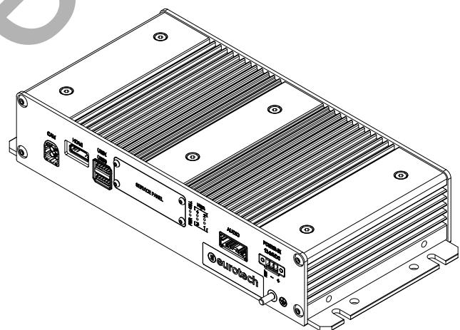
Fig. 1 - The DynaGATE 10-14
4.2 Intended use and not allowed uses of the product
The product is intended for professional use and must be installed by qualified personnel only.
The product must be installed in a secured location, accessible to authorized personnel only (for example in a cabinet / technical compartment).
The product is intended to be installed horizontally on a plane surface.
4.2.1 Deterministic output notice

NOTICE
This product is not intended to be physically or logically connected to an automation process.
4.2.2 Intended use
The DynaGATE 10-14 is an E-Mark certified Edge Gateway for Public Transport and Road Vehicles that enables a fast transition to ITxPT both in existing and new deployments.
The DynaGATE 10-14 must:
- Be installed in a secured location, only accessible to authorized personnel (for example in a cabinet/ technical compartment), and not exposed to atmospheric agents
- Be used indoors or in automotive applications. Before you use the DynaGATE 10-14 in automotive applications:
in the EU, switch-OFF the Wi-Fi frequency band 15150MHz - 5250MHz
in the US and Canada, switch-OFF the Wi-Fi frequency bands 15150 MHz - 5250 MHz and 5745 MHz - 5825 MHz
- Be used with appropriate interconnecting and power cables
-
Be used with an external DC power supply source that:
-
must meet the requirements stated on the identification label of the product
- must deliver a minimum power of 65 W
- must include an external Type F fuse on the line coming from the negative terminal (a 3 A Type F fuse is appropriate for 24VDC operation).
4.2.3 Not allowed uses
Do not use the DynaGATE 10-14:
- in railway applications
- in defense applications
outdoors - in safety-critical applications
- in environments with potentially explosive atmospheres
- if not installed according to the instructions and warnings contained in this document.
When used in automotive applications in any EU Member State, do not use the DynaGATE 10-14 with the following Wi-Fi bands enabled: 5150 MHz – 5250 MHz and 5745 MHz – 5825 MHz.
4.3 Technical specifications
The DynaGATE 10-14 family has the following technical specifications:
| Ordering Code: DYGATE-10-14-xx | ||||||||
| Ordering Code: HW(1) Only | -01 | -03 | -04 | -05 | -07 | -09 | ||
| Ordering Code: HW + EL(2) | -21 | -23 | -24 | -25 | -27 | -29 | ||
| Ordering Code: HW + EL + ESF(3) | -31 | -33 | -34 | -35 | -37 | -39 | ||
| PROCESSOR | CPU | NXP i.MX 8M Plus, 4 Core ARM Cortex A53 1.8 GHz + 1 Core ARM Cortex M7 800 MHz | ||||||
| ACCELERATORS | Neural Processor | Integrated, 2.3 TOPS | ||||||
| 2D/3D GPU | Integrated, Shader, Vivante GC520L, Vivante GC7000UL | |||||||
| MEMORY | RAM | 4 GB LPDDR4 (Up to 8 GB); Inline ECC (Contact Eurotech for more information) | ||||||
| STORAGE | Embedded | 32 GB eMMC (Up to 128 GB) | ||||||
| Other | 1x microSD Slot (User Accessible) | |||||||
| I/O INTERFACES | Ethernet | 2x GbE; M12 X-Coded | 4x GbE; M12 X-Coded | 2x GbE; M12 X-Coded | ||||
| USB | 2x Host 3.0 (Noise and Surge Protected); Type A | |||||||
| CAN | 2x CAN-FD bus, Protected and Isolated with Termination Resistors | |||||||
| Serial | 2x RS-232/422/485 | 4x RS-232/422/485 | ||||||
| Serial Protection | Isolated, Surge Protected, with Termination Resistors and Fail-safe Receivers | |||||||
| Debug Console | 1x USB Serial Console | |||||||
| Camera Input | Ethernet (IP Camera) | Ethernet (IP Camera) and 4x GMSL 3.12 Gbps Coax Input; FAKRA | Ethernet (IP Camera) | |||||
| Digital I/O | 11x Digital Input 36 V, 1.5 kV Isolated; 4x Digital Outputs (36 V AC/DC), 500 mA sink, 1 kHz Max Switching, 1.5 kV Isolated; 3x Digital Outputs (24 V DC, Log-level, Non-isolated) | |||||||
| Analog I/O | 2x Analog Inputs 36 V, 11-bit, Isolated | |||||||
| Video Out | 1x HDMI with 2D/3D Acceleration | |||||||
| Audio | Stereo Line-level Audio Output | |||||||
| RADIO INTERFACES | Internal Cellular | No | LTE Cat 4 (Global) - Factory Options: Cat 6, 12, 18; 5G Ready | |||||
| SIM Slot | No | 2x microSIM (User Accessible; LTE CAT 4 only supports 1x) | ||||||
| GNSS | GPS, Galileo, GLONASS, BeiDou, QZSS | |||||||
| GNSS type | UDR(4) | UDR | RTK(5) (sub-meter) | UDR | UDR | UDR | ||
| Wi-Fi | No | 802.11 a/b/g/n/ac (2.4 GHz, 5 GHz) | ||||||
| Bluetooth | No | BT/BLE5.0 (2.4 GHz) | ||||||
| Ext. Antennas | No | 2x Cellular, 1x Wi-Fi/BT, 1x GNSS; FAKRA (Factory Option: SMA/RP-SMA) | ||||||
| CYBERSECURITY (HARDWARE) | TPM | TPM 2.0 | ||||||
| Hardware | Yes (Enclosure and Service Panel - Always-on Monitoring and Event Logging with Time Stamping) | |||||||
| Ordering Code: DYGATE-10-14-xx | ||||||||
| OTHER | RTC | Yes (supercap backup) | ||||||
| Watchdog | Yes - CPU built-in | |||||||
| EEPROM | 256 Kbit | |||||||
| Temp. Sensor | Yes | |||||||
| Accelerometer | 3D Accelerometer / 3D Gyroscope | |||||||
| LEDs | 1x Power Blue, 1x Cellular Activity Green, 4x User Configurable (2x Green/Yellow, 2x Green/Red) | |||||||
| Buttons | 1x Reset Button 1x Programmable Button | |||||||
| EXPANSIONS | Internal Expansions | Internal, M.2, Internal Bay #1, Internal Bay #2 (Contact Factory for Expansion Options) | ||||||
| POWER | Input | Nominal: 12 and 24 V DC; Range: 9 to 35 V DC with Transient Protection and Vehicle Ignition Sense | ||||||
| Power Backup | Safe-shutdown; Configurable Sleep Timer, to Manage Shutdown | |||||||
| Consumption | Typical: 10 W; Sleep < 2.5 W | |||||||
| ENVIRONMENT | Operating Temp. | -40 to +70 °C | ||||||
| Storage Temp. | -40 to +70 °C | |||||||
| Humidity | 5 to 95% Relative Humidity (Non-condensing) at +40°C | |||||||
| CERTIFICATIONS | Cybersecurity | Secure Boot, TrustZone Architecture, PSA Level 1, California SB-327, Always-on Antitamper Monitor, TPM 2.0; IEC 62443-4-1/-4-2 - For Hardened Production-only Images | ||||||
| IoT Platform | AWS IoT Core Qualified; Microsoft Azure Certified; Everyware Cloud Native | |||||||
| Regulatory | EU/UK: CE(*), UKCA(*); North America: FCC(*), ISED(*); Japan: TELEC(*), JATE(*); Other Countries: Factory Option | |||||||
| Cellular | No | EU/UK: RED(*), Any Carriers; North America: PTCRB(*), AT&T(*), Verizon(*); Japan: Any Carriers; Other Countries: Factory Option | ||||||
| Safety | EN 62368-1(*), UL 62368-1($) | |||||||
| Road | E-Mark, ITxPT | |||||||
| Environmental | RoHS3, REACH | |||||||
| Ingress | IP40 | |||||||
| MECHANICAL | Enclosure | Material: Aluminum; Color: Black Anodized | ||||||
| Dimensions | 270 x 123 x 51mm (WxDxH) - Excluded Connectors | |||||||
(1) HW = Hardware
(2) EL = Eurotech Everyware Linux
(3) ESF = Everyday Software Framework
(4) UDR = Untethered Dead Reckoning
(5) RTK = Real Time Kinematics
(S) UL, NRTL listing Factory Option
(*) Ongoing
| SOFTWARE | ||
| SOFTWARE | OS | Eurotech Evereware Linux |
| SDK | Yocto-based Eclipse Tooling, Azul Java | |
| IoT Framework | Everyware Software Framework (Java/OSGi) | |
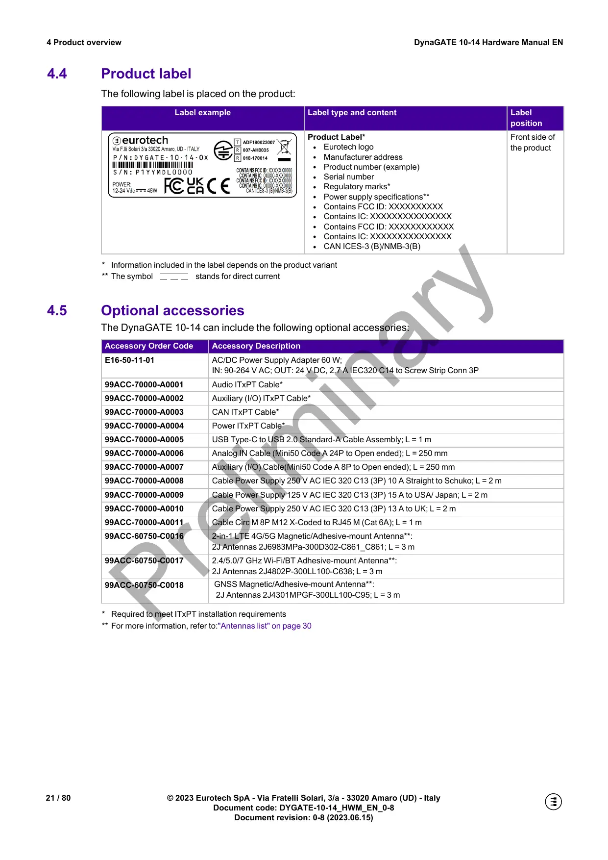
4.4 Product label
The following label is placed on the product:
| Label example | Label type and content | Label position |
| ®eurotech Via F. lili Solari 3/a 33020 Amaro, UD - ITALY P/N: DY GATE - 10 - 14 - 0X S/N: P1YYMDL0000 POWER: 12-24 Vdc----48W | Product Label* • Eurotech logo • Manufacturer address • Product number (example) • Serial number • Regulatory marks* • Power supply specifications** • Contains FCC ID:XXXXXXXXX • Contains IC:XXXXXXXXXX • Contains FCC ID:XXXXXXXXX • Contains IC:XXXXXXXXXX • CAN ICES-3(B)/NMB-3(B) | Front side of the product |
- Information included in the label depends on the product variant
** The symbol --- stands for direct current
4.5 Optional accessories
The DynaGATE 10-14 can include the following optional accessories:
| Accessory Order Code | Accessory Description |
| E16-50-11-01 | AC/DC Power Supply Adapter 60 W;IN: 90-264 V AC; OUT: 24 V DC, 2.7 A IEC320 C14 to Screw Strip Conn 3P |
| 99ACC-70000-A0001 | Audio ITxPT Cable* |
| 99ACC-70000-A0002 | Auxiliary (I/O) ITxPT Cable* |
| 99ACC-70000-A0003 | CAN ITxPT Cable* |
| 99ACC-70000-A0004 | Power ITxPT Cable* |
| 99ACC-70000-A0005 | USB Type-C to USB 2.0 Standard-A Cable Assembly; L = 1 m |
| 99ACC-70000-A0006 | Analog IN Cable (Mini50 Code A 24P to Open ended); L = 250 mm |
| 99ACC-70000-A0007 | Auxiliary (I/O) Cable(Mini50 Code A 8P to Open ended); L = 250 mm |
| 99ACC-70000-A0008 | Cable Power Supply 250 V AC IEC 320 C13 (3P) 10 A Straight to Schuko; L = 2 m |
| 99ACC-70000-A0009 | Cable Power Supply 125 V AC IEC 320 C13 (3P) 15 A to USA/ Japan; L = 2 m |
| 99ACC-70000-A0010 | Cable Power Supply 250 V AC IEC 320 C13 (3P) 13 A to UK; L = 2 m |
| 99ACC-70000-A0011 | Cable Circ M 8P M12 X-Coded to RJ45 M (Cat 6A); L = 1 m |
| 99ACC-60750-C0016 | 2-in-1 LTE 4G/5G Magnetic/Adhesive-mount Antenna**:2J Antennas 2J6983MPa-300D302-C861_C861; L = 3 m |
| 99ACC-60750-C0017 | 2.4/5.0/7 GHz Wi-Fi/BT Adhesive-mount Antenna**:2J Antennas 2J4802P-300LL100-C638; L = 3 m |
| 99ACC-60750-C0018 | GNSS Magnetic/Adhesive-mount Antenna**:2J Antennas 2J4301MPGF-300LL100-C95; L = 3 m |
- Required to meet ITxPT installation requirements
** For more information, refer to:"Antennas list" on page 30
5 CERTIFICATIONS
Note about the Declaration of Conformity
Upon request, Eurotech can provide the product Declaration of Conformity.
For more information, refer to: https://www.eurotech.com/support.
This chapter gives the following information:
5.1 CE marking 23
5.2 REACH compliance 24
5.3 UKCA marking 24
5.4 FCC compliance 25
5.5 ISED Canada compliance 27
5.6 MIC Japan 29
5.7 Antennas list 30
5.1 CE marking
This product is CE marked and complies with the essential requirements and other relevant requirements of the directives reported in the following sections.
Eurotech does not approve the use of this product with equipment (for example: power supplies, personal computers, etc.) that is not CE marked and that is not compliant with the requirements specified in this Hardware Manual.

5.1.1 Safety
This product complies with the standard IEC EN 62368-1 on the safety requirements in information and communication technology equipment.
5.1.2 RoHS 3 compliance
This product complies with the following Directives:
- Directive 2011/65/EU on the restriction of the use of certain hazardous substances in electrical and electronic equipment
- Commission Delegated Directive (EU) 2015/863 as regards the list of restricted substances.
5.1.3 Packaging and packaging waste
This product complies with the Directive 94/62/EC on packaging and packaging waste.
5.1.4 Product disposal and recycling
This product, at the end of its life cycle, must be collected separately and managed in accordance with the provisions of the Directive 2012/19/EU on waste of electrical and electronic equipment (WEEE).
For more information, refer to: "The WEEE label" below.
5.1.4.1 The WEEE label
This symbol, placed on the product, indicates that the product at the end of its life cycle must be sent to separate collection facilities for recovery and recycling. Because of the substances present in the product, improper disposal can cause damage to human health and to the environment.
For collecting and recycling information, refer to: https://www.eurotech.com/support.

5.1.5 RED compliance (all product variants but: -x1)
This product complies with the Directive 2014/53/EU on the harmonization of the laws of the Member States relating to the making available on the market of radio equipment.
Modification statement
Eurotech does not approve any changes or modifications to this product by the user. Any changes or modifications could void the user's authority to operate this product.
5.1.5.1 Class II product and EU restrictions on 5 GHz Wi-Fi usage
According to Commission Decision 2000/299/EC, establishing the initial classification of radio equipment and telecommunications terminal equipment and associated identifiers, the product falls within the scope of Class II.
The WiFi frequency band 5150-5350 MHz is restricted to indoor use only.
Dynamic Frequency selection (DFS) as master or subordinate is not supported by the product.
| AT | BE | BG | CH | CY | CZ | DE |
| DK | EE | EL | ES | FI | FR | HR |
| HU | IE | IT | IS | LI | LT | LU |
| LV | MT | NL | NO | PL | PT | RO |
| SE | SI | SK | TR | UK(NI) | ||
5.2 REACH compliance
This product is assessed to be compliant with the regulation (EC) No 1907/2006 concerning the Registration, Evaluation, Authorisation and Restriction of Chemicals (REACH), with the exceptions allowed by the EU Technical Committee.
Eurotech has set in place a monitoring process to assess compliance to REACH regulation.
For details and more information, refer to: https://www.eurotech.com/support.
5.3 UKCA marking
This product is UKCA marked and complies with the relevant UK Statutory Instruments and their amendments:
2017 No 1206 The Radio Equipment Regulations 2017
2012 No 3032 The Restriction of the Use of Hazardous Substances in Electrical and Electronic Equipment Regulations 2012
Eurotech does not approve the use of this product with equipment (for example: power supplies, personal computers, etc.) that is not UKCA marked and that is not compliant with the requirements specified in this Hardware Manual.

5.4 FCC compliance
5.4.1 FCC marking
This product is FCC marked and complies with the regulatory information reported in the following sections.
Eurotech is not responsible for the use of the product together with equipment (for example: power supplies, personal computers, etc.) that are not FCC marked and not compliant with the requirements specified in this instructions for use.
Modification statement
Changes or modifications not expressly approved by the party responsible for compliance could void the user's authority to operate the equipment.
5.4.2 FCC compliance: Class B Digital Device
This device complies with part 15 of the FCC Rules. Operation is subject to the following two conditions: (1) this device may not cause harmful interference, and (2) this device must accept any interference received, including interference that may cause undesired operation.
Note: This equipment has been tested and found to comply with the limits for a Class B digital device, pursuant to part 15 of the FCC Rules. These limits are designed to provide reasonable protection against harmful interference in a residential installation.
This equipment generates, uses and can radiate radio frequency energy and, if not installed and used in accordance with the instructions, may cause harmful interference to radio communications. However, there is no guarantee that interference will not occur in a particular installation.
If this equipment does cause harmful interference to radio or television reception, which can be determined by turning the product OFF and ON, the user is encouraged to try to correct the interference by one or more of the following measures:
- Reorient or relocate the receiving antenna
- Increase the separation between the product and the receiver
- Connect the product into an outlet on a circuit different from that to which the receiver is connected
- Consult the dealer or an experienced radio/TV technician for help
5.4.3 RF radiation exposure statement
This device complies with FCC radiation exposure limits set forth for an uncontrolled environment. The antenna should be installed and operated with minimum distance of 20~cm between the radiator and your body.
This device and its antenna(s) must not be co-located or operating in conjunction with any other antenna or transmitter except in accordance with FCC multi-transmitter product procedures.
5.4.4 FCC restrictions on 5 GHz Wi-Fi usage
The product is limited to indoor operation and can only be operated in the frequency bands: 5150 MHz – 5250 MHz and 5745 MHz – 5825 MHz.
For the FCC information stated on the product label, see: "Product label" on page 21.
5.5 ISED Canada compliance
This device contains licence-exempt transmitter(s)/receiver(s) that comply with Innovation, Science and Economic Development Canada's licence-exempt RSS(s). Operation is subject to the following two conditions: (1) this device may not cause harmful interference, and (2) this device must accept any interference received, including interference that may cause undesired operation of the device.
This device has been approved by Innovation, Science and Economic Development Canada to operate with the antenna types listed below, with the maximum permissible gain indicated. Antenna types not included in this list that have a gain greater than the maximum gain indicated for any type listed are strictly prohibited for use with this device.
5.5.1 ISED compliance: Class B Digital Device
ICES-003 Class B Notice - Avis NMB-003, Classe B.
This Class B digital apparatus complies with Canadian ICES-003.
5.5.2 RF radiation exposure statement
This product complies with ISED radiation exposure limits set forth for an uncontrolled environment. The antenna should be installed and operated with minimum distance of 20 cm between the radiator and your body.
This device and its antenna(s) must not be co-located or operating in conjunction with any other antenna or transmitter except in accordance with ISED multi-transmitter product procedures.
This device complies with Health Canada's Safety Code. The installer of this device should ensure that RF radiation is not emitted in excess of the Health Canada's requirement
5.5.3 ISED restrictions on 5 GHz Wi-Fi usage
The product is limited to indoor operation and can only be operated in the frequency bands: 5150 MHz – 5250 MHz and 5745 MHz – 5825 MHz.
For the ISED information stated on the product label, see: "Product label" on page 21.
5.5.5 Responsible parties: Canadian Representative contact information
The Canadian Representative has the following contact information:
| Contact Information | |
| Company Name | Canadian Certification Consulting, Inc. |
| Company Number(*) | 10842A |
| Company Address | 2210 Horizon Drive, Suite 17 |
| City | West Kelowna |
| Province/State | BC |
| Postal Code | V1Z 3L4 |
| Country | Canada |
| Contact Name | Jon Hughes |
| Title | President |
| Phone Number | 1-250-575-1719 |
| info@can-cert.com | |
This product contains wireless equipment that comply with the construction design certification based on the Radio Law of MIC (Ministry of Internal Affairs and Communications) Japan.
A radio station license is not required to use this wireless equipment in Japan.
The certification numbers are the following:
| Product Wireless Equipment | Certification Numbers |
| Quectel_EM05-G | [R] 201-190133 [T] AD 19 0040 201 |
| Telit WE866C6-P | [R] 201-210263 [T] D 21 0068 201 |
The product certification mark is the following:


201-190133

AD 19 0040 201

201-210263

D 21 0068 201
Modification statement
Eurotech does not approve any changes or modifications to this product by the user. Any changes or modifications could void the user's authority to operate this product.
5.7 Antennas list
The DynaGATE 10-14 has been certified with the following antennas:
In the EU, antennas must be used in compliance with the RED requirements.
5.7.2 Notice for UK
In the UK, antennas must be used in compliance with the UK RER requirements.
5.7.3 Notice for US
In the US, antennas must be used in compliance with the FCC requirements.
In the Canada, antennas must be used in compliance with the ISED requirements.
This chapter gives the following information:
6.1 Front side interfaces overview 32
6.2 LED indicators overview 33
6.3 Service Panel overview 34
6.4 Rear side interfaces overview 40
6.1 Front side interfaces overview
The Front side interfaces are as follows.
Connectors availability depends on product variant. For more information, refer to:"Technical specifications" on page 19.
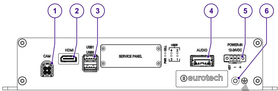
Fig. 2 - Front side interfaces layout
Tab. 1 - Front side interfaces description
| Ref # | Label | Description |
| 1 | CAM | 4x GMSL Camera IN connector (only for product variant: -x5) |
| 2 | HDMI | HDMI OUT connector |
| 3 | USB0, USB1 | 2x Host USB ports (USB 3.0 Type A; USB0 on the bottom; USB1 on the top) |
| 4 | AUDIO | Audio Interface |
| 5 | POWER IN | Power IN connector |
| 6 | Earth connection terminal |
6.2 LED indicators overview
The LED indicators A are as follows:
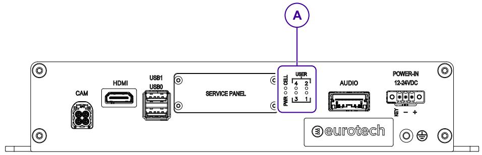
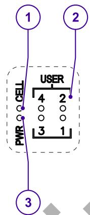
Fig. 3 - LED indicators layout
Tab. 2 - LED indicators description
| Ref # | Label | Color | Description |
| 1 | CELL | Green | Internal Cellular Modem activity (all product variants but: -x1) • LED ON: Modem ON • LED blinking: Modem connected to cellular network |
| 2 | USER1 | Bi-color Green / Yellow | General purpose LEDs |
| USER2 | |||
| USER3 | Bi-color Green / Red | ||
| USER4 | |||
| 3 | PWR | Blue | External power source status: • LED ON: External power source is present • LED OFF: External power source is missing (regardless of the KEY Signal (IGN_IN) status) |
6.3 Service Panel overview
The Service Panel A is placed on the front side of the product and contains the Service Interfaces:
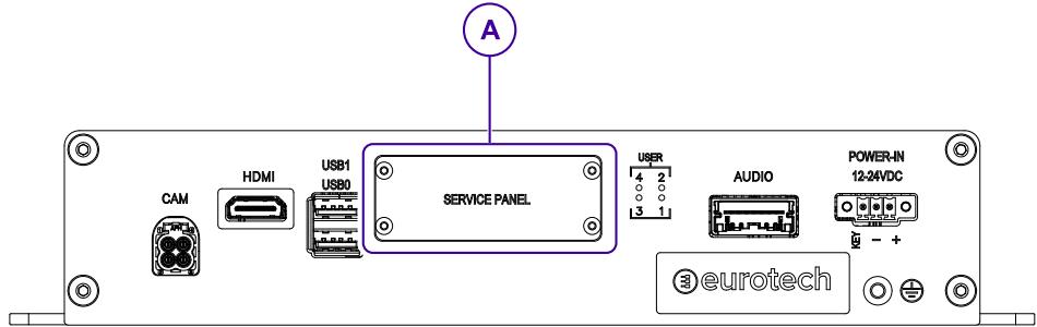
Fig. 4 - Service Panel layout
6.3.1 How to remove the Service Panel cover

NOTICE
The IP rating is not maintained if the Service Panel cover is removed.
Do not use the product for a long period with the Service Panel cover removed, or dust and other particulates will go into the product.
If you must have access to the Service Panel for a long period, use appropriate precautions to stop dust and other particulates.
To remove the Service Panel cover, use a 1.5mm hex key and release the four M2.5 x 5 mm Button Head Hexagon Socket Drive Screws (see Fig. 5 below):
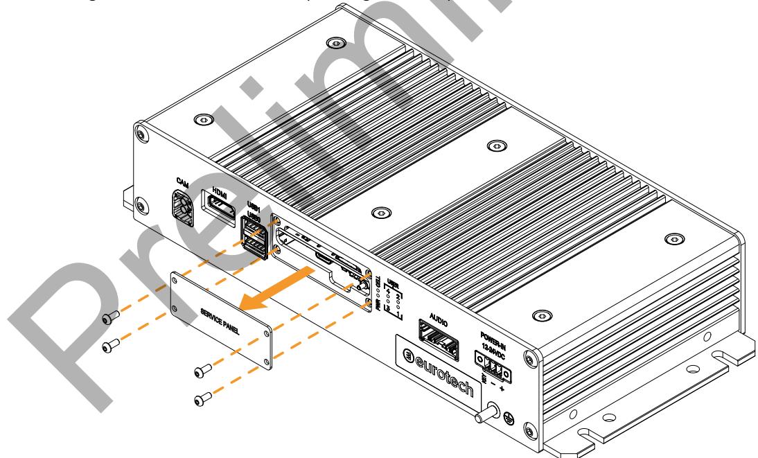
Fig. 5 - How to remove the Service Panel cover
6.3.2 Service Interfaces overview
The Service Interfaces are as follows:
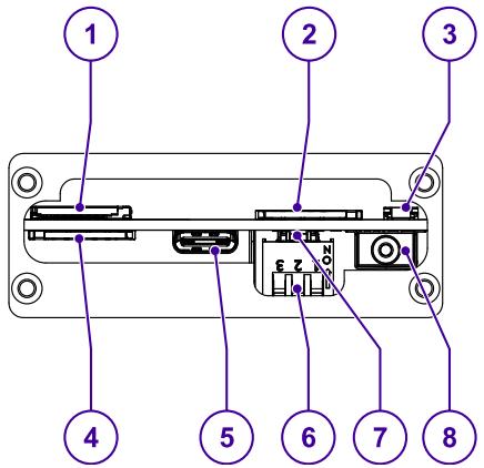
Fig. 6 - Service Interfaces layout
Tab. 3 - Service Interfaces description
| Ref # | Description |
| 1 | MicroSD Card Push-push Connector |
| 2 | Primary MicroSIM Card Push-push Connector |
| 3 | Reset Button |
| 4 | Secondary MicroSIM Card Push-push Connector (not supported for LTE Cat 4 internal cellular modem) |
| 5 | USB Serial Console (USB Type-C Female connector) |
| 6 | DIP switch for boot mode selection and for ignition key control |
| 7 | User-programmable Button (default: factory restore) |
| 8 | Anti-Tamper sensor for Service Panel cover |
6.3.3 MicroSD and MicroSIM card connectors
The connectors for the MicroSD and MicroSIM cards are placed in the Service Panel. Both connectors are push-push type (push to insert, push to eject).

NOTICE
Only the top-side SIM card connector supports the LTE Cat 4 internal cellular modem. The bottom-side SIM card connector is reserved for future use.
Disable the SIM PIN (Personal Identification Number) before you insert the SIM card. If the SIM PIN is enabled, the cellular connection does not work.
To insert the MicroSD and MicroSIM cards, orient them as in the figures below:
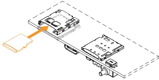
Fig. 7 - MicroSD card orientation
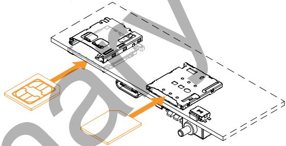
Fig. 8 - MicroSIM card orientation
6.3.4 Reset button
The DynaGATE 10-14 has a reset button that triggers a hardware reset of the device.
6.3.5 USB Serial Console
The USB Serial Console is provided through a USB 2.0 Type-C receptacle.
With this receptacle you can use the following mating cables:
- USB 2.0 Type-C Standard Cable assembly.
This cable has USB 2.0 Type-C plug at both ends - USB Type-C to USB 2.0 Standard-A Cable Assembly.
This cable has a USB 2.0 Type-C plug at one end, and a USB 2.0 Standard-A plug at the other end.
6.3.5.1 USB Serial Console connector specifications
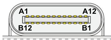
Connector Layout:
Connector Specifications:
- USB 2.0 Type-C receptacle
Mating Connector Specifications:
USB2.0 Type-C plug
Connector Pinout (pins not listed are reserved):
| Pin # | Signal | Type | Description |
| A1 | GND | P | Ground return |
| A4 | VBUS | P | Bus Power |
| A5 | CC1 | IO | Configuration Channel |
| A6 | Dp1 | IO | Positive half of the USB 2.0 differential pair – Position 1 |
| A7 | Dn1 | IO | Negative half of the USB 2.0 differential pair – Position 1 |
| A9 | VBUS | P | Bus Power |
| A12 | GND | P | Ground return |
| B12 | GND | P | Ground return |
| B9 | VBUS | P | Bus Power |
| B7 | Dn2 | IO | Negative half of the USB 2.0 differential pair – Position 2 |
| B6 | Dp2 | IO | Positive half of the USB 2.0 differential pair – Position 2 |
| B5 | CC2 | IO | Configuration Channel |
| B4 | VBUS | P | Bus Power |
| B1 | GND | P | Ground return |
6.3.6 DIP switch definitions
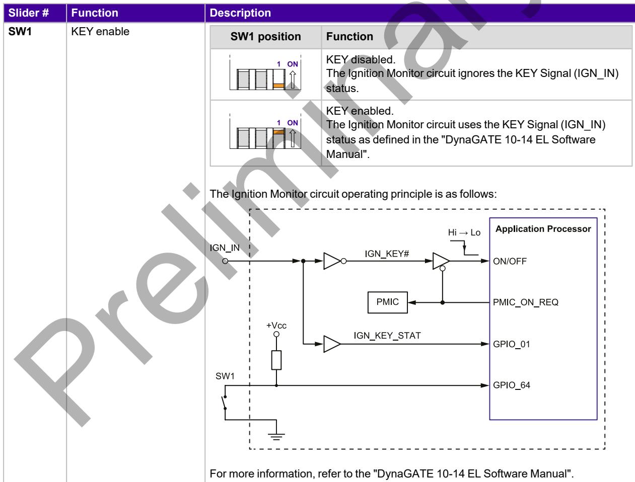
The DynaGATE 10-14 has a 3-slider DIP switch that controls the following functions:
- KEY enable - slider SW1
- Boot mode selection - sliders SW2 and SW3.
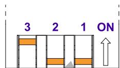
To understand the position of the sliders, refer to the arrow that points to the ON direction.
Example: In the following figure, SW1 and SW2 are OFF, SW3 is ON:
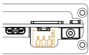

The following table shows the sliders positions and their functions:
| Slider # | Function | Description | |
| SW2-SW3 | Boot mode selection1 | SW2-SW3 positions | Function |
| 3 2 ON | Boot according to internal fuse setting (default: boot from internal eMMC) | ||
| 3 2 ON | Boot from internal eMMC | ||
| 3 2 ON | Reserved for future use | ||
| 3 2 ON | Boot from microSD card | ||
6.3.7 User-programmable button: factory restore

NOTICE
The restore operation erases all user data and configuration: use it with caution.
The DynaGATE 10-14 features a user-programmable button that by default activates a factory restore functionality. This functionality restores the DynaGATE 10-14 from a failed state.
For more information, refer to:"DynaGATE 10-14 EL Software Manual".
6.4 Rear side interfaces overview
The Rear side interfaces are as follows1:
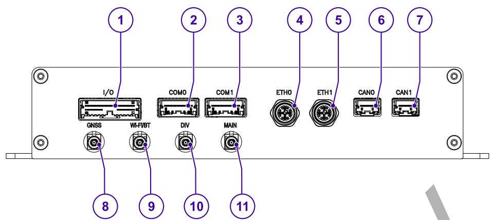
(for product variants: -31, -33, -34, -35)
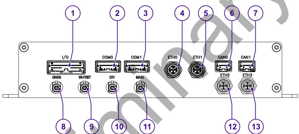
(only for product variant: -x7)
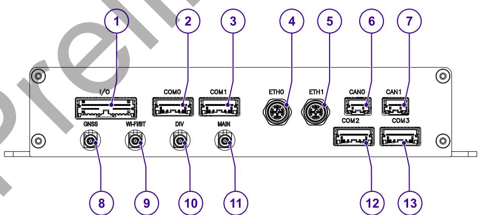
(only for product variant: -x9)
Fig. 9 - Rear side interfaces layout
| Ref # | Label | Description |
| 1 | I/O | Digital IN/OUT and Analog IN |
| 2 | COM0 | Serial port COM0 |
| 3 | COM1 | Serial port COM1 |
| 4 | ETH0 | Ethernet port ETH0 |
| 5 | ETH1 | Ethernet port ETH1 |
| 6 | CAN0 | CAN ports CAN0 |
| 7 | CAN1 | CAN ports CAN1 |
| 8 | GNSS | Antenna connector for GNSS |
| 9 | Wi-Fi/BT | Antenna connector for Wi-Fi/Bluetooth (all product variants but: -x1) |
| 10 | DIV | Diversity antenna connector for internal cellular modem (all product variants but: -x1) |
| 11 | MAIN | Main antenna connector for internal cellular modem (all product variants but: -x1) |
only for product variant: -x7
| 12 | ETH2 | Ethernet port ETH2 |
| 13 | ETH3 | Ethernet port ETH3 |
only for product variant: -x9:
Tab. 4 - Rear side interfaces description
| 12 | COM2 | Serial port COM2 |
| 13 | COM3 | Serial port COM3 |
7 FRONT INTERFACES IN DETAIL
The interfaces availability depends on the product variant. For more information, refer to:"Technical specifications" on page 19.
This chapter gives the following information:
7.1 CAM (Camera IN) connector (only for product variant: -x5) 43
7.2 HDMI connector 44
7.3 USB connectors 45
7.4 Audio connector (AUD) 46
7.5 PWR (Power IN) connector 48
7.6 Earth connection terminal 49
7.1 CAM (Camera IN) connector (only for product variant: -x5)
The DynaGATE 10-14 has a connector (CAM) on the front side that provides 4x GMSL (1.5 Gbps to CSI2) camera inputs.
7.1.1 CAM connector specifications
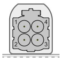
Connector Layout:
Connector Pinout:
| Pin # | Signal | Type | Description |
| 1 | IN0+ | I | GMSL Input 0+ |
| 2 | IN1+ | I | GMSL Input 1+ |
| 3 | IN2+ | I | GMSL Input 2+ |
| 4 | IN3+ | I | GMSL Input 3+ |
Connector Specifications:
AUTOMATE Type A Mini-FAKRA Quad Port
Code: Z - Water Blue (Universal)
- Gender: Male (plug)
Mating Connector Specifications:
AUTOMATE Type A Mini-FAKRA Quad Jack
Code: Z - Water Blue (Universal)
- Gender: Female (socket)
7.2 HDMI connector
The DynaGATE 10-14 an HDMI output on the front side.
7.2.1 HDMI connector specifications
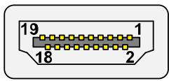
Connector Layout:
Connector Specifications:
- HDMI Type-A Socket
Gender: Female
Mating Connector Specifications:
- Cable-mount HDMI Type-A Plug
Gender: Male
Connector pinout:
| Pin # | Signal | Description |
| 1 | D2+ | TMDS Data2+ |
| 2 | D2_SH | TMDS Data2 Shield |
| 3 | D2- | TMDS Data2- |
| 4 | D1+ | TMDS Data1+ |
| 5 | D1_SH | TMDS Data1 Shield |
| 6 | D1- | TMDS Data1- |
| 7 | D0+ | TMDS Data0+ |
| 8 | D0_SH | TMDS Data0 Shield |
| 9 | D0- | TMDS Data0- |
| 10 | CK+ | TMDS Clock+ |
| 11 | CK_SH | TMDS Clock Shield |
| 12 | CK- | TMDS Clock- |
| 13 | CEC | Consumer Electronics Control |
| 14 | NC | Not Connected |
| 15 | SCL | I²C serial clock for DDC |
| 16 | SDA | I²C serial data for DDC |
| 17 | DGND | DDC/CEC Ground |
| 18 | +5V | +5V Power |
| 19 | HPD | Hot Plug Detect |
7.3 USB connectors
The DynaGATE 10-14 has 2x Host 3.0 USB ports on the front side:
- USB 0; max load: 900 mA
USB 1; max load: 900mA
The ports are noise and surge protected.
7.3.1 USB 0 and USB 1 connectors specifications

Connector Layout:
Connector Specifications:
- USB Type-A socket
Gender: Female
Mating Connector Specifications:
- USB Type-A plug
Gender: Male
Connector Pinout:
| Pin # | Signal | Type | Description |
| 1 | V+ | P | +5V |
| 2 | D- | IO | Data- |
| 3 | D+ | IO | Data+ |
| 4 | GND | P | Ground |
7.4 Audio connector (AUD)
The DynaGATE 10-14 has the following audio interfaces on the front side:
- 1x Single ended, unbalanced stereo audio output
- 3x Digital audio outputs protected and non-isolated, for channel selection
- External cable loom to map to ITxPT audio connector.
7.4.1 Audio specifications
Stereo audio output specifications:
Output: 0 to 1V
Output impedance: < 10k (1 kHz)
Frequency range: 20 Hz to 20 kHz (-30 dB to +30 dB)
Digital audio output specifications:
Non-isolated - galvanically linked to power input
Output high = +2.6 V DC to Vin (Power IN+)
Output low = 0V to +2.5VDC
- Protected internally with 50mA resettable fuse
7.4.2 Audio connector specifications

NOTICE
To make sure that the connection keeps the ITxPT compliance, use the optional accessory 99ACC-70000-A0001: Audio ITxPT cable (described on the next page).
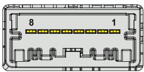
Connector Layout:
Connector Specifications:
- Mini50 Unsealed Header
- Single Row, 8 Circuits
- Polarization Option B
Gray
Mating Connector Specifications:
- Receptacle:
Mini50 Unsealed Receptacle
Single Row, 8 Circuits
- Polarization Option B
Gray
Crimp Terminal:
- Mini50 Unsealed Crimp Terminal
L-Grip
Tin plated
Example:
Manufacturer:Molex
Part number Receptacle: 34791-0081
Part number Crimp Terminal: 560023-0448
Connector Pinout:
| Pin # | Signal | Type | Description |
| 1 | OUT_L | O | Audio Out Left |
| 2 | OUT_R | O | Audio Out Right |
| 3 | AGND | P | Analog Power Return (Ground) |
| 4 | Reserved | R | Reserved |
| 5 | DIGO1 | O | Audio Digital Output 1 (non-isolated) |
| 6 | DIGO2 | O | Audio Digital Output 2 (non-isolated) |
| 7 | DIGO3 | O | Audio Digital Output 2 (non-isolated) |
| 8 | GND | P | Ground |
7.4.3 99ACC-70000-A0001: Audio ITxPT cable
Con1: Mini50 Unsealed Receptacle, Single Row, 8 Circuits, Polarization Option B, Gray
Con2: MCP2.8 GEH Receptacle, 9 Circuits, Polarization Code A, Yellow
Length: 50~cm
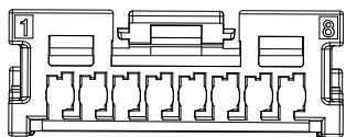
Con1 - Insert contacts side view (to DynaGATE 10-14)
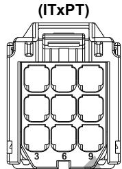
Con2 - Insert contacts side view
Connections:
| Con2 Pin (ITxPT) | Con1 Pin (to DynaGATE 10-14) | ITxPT Signal | DynaGATE 10-14 function |
| 1 | 1 | Left channel | Audio Out Left |
| 2 | 3 | Common Ground | Analog Power Return (Ground) |
| 3 | 2 | Right Channel | Audio Out Right |
| 4 | Not connected | ||
| 5 | Not connected | ||
| 6 | Not connected | ||
| 7 | 5 | 1st(prio 1) | Audio Digital Output 1 (non-isolated) |
| 8 | 6 | 2nd(prio 2) | Audio Digital Output 2 (non-isolated) |
| 9 | 7 | 3rd(prio 3) | Audio Digital Output 3 (non-isolated) |
7.5 PWR (Power IN) connector
The DynaGATE 10-14 has a connector (PWR) on the front side that is the power input interface of the product.
For more information, refer to: "Power IN connector specifications" on page 73.

NOTICE
To make sure that the connection keeps the ITxPT compliance, use the optional accessory 99ACC-70000-A0004: Power ITxPT cable (described below).
7.5.1 99ACC-70000-A0004: Power ITxPT cable
Con1: Pluggable screw terminal block, Female, 3-pin, 3.5 mm pitch
Con2: MCP2.8 GEH Receptacle, 6 Circuits, Polarization Code A, Blue
Length: 50~cm
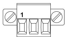
Con1 - Insert contacts side view (to DynaGATE 10-14)
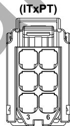
Con2 - Insert contacts side view
Connections:
| Con2 Pin (ITxPT) | Con1 Pin (to DynaGATE 10-14) | ITxPT Signal | DynaGATE 10-14 function |
| 1 | 1 | 24V after manual switch | Positive power supply input |
| 2 | 3 | GROUND | Negative power supply input |
| 3 | 2 | 24V after ignition switch | KEY Signal |
| 4 | Not connected | Full power available (optional) | |
| 5 | reserved | ||
| 6 | Not connected | 24V after main switch (optional) |
7.6 Earth connection terminal
The DynaGATE 10-14 has a terminal on the front side that is the earth connection interface of the product.
Always use this terminal to connect the product to an earth point in the installation.
For more information, refer to: "Product power requirements" on page 72.
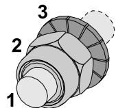
Terminal Layout:

Terminal Label:
Terminal Parts:
| Part # | Description |
| 1 | M4 stud bolt (length = 12 mm) |
| 2 | M4 lock nut |
| 3 | M4 serrated lock washer |

NOTICE
The earthing conductor to be connected to this terminal must have a size of at least 1mm^2
8 REAR INTERFACES IN DETAIL
The interfaces availability depends on the product variant. For more information, refer to:"Technical specifications" on page 19.
This chapter gives the following information:
8.1 I/O (Digital I/Os and Analog INs) connector 51
8.2 COM connectors 54
8.3 Ethernet connectors 57
8.4 CAN connectors 58
8.5 GNSS 60
8.6 Wi-Fi and Bluetooth (all product variants but: -x1) 62
8.7 Cellular Modem (all product variants but: -x1) 64
8.1 I/O (Digital I/Os and Analog INs) connector
The DynaGATE 10-14 has a connector (I/O) on the rear side that provides:
11x Digital Inputs (individually opto-isolated - common AGND)
- 4x Digital Outputs (individually opto-isolated)
- 2x Analog Inputs (jointly isolated with digital inputs AGND)
8.1.1 I/O specifications
Digital IN specifications:
- Optoisolation 1.5kV
- Logic high +3 to 36 V DC
- Logic low 0 to +1~V
- Input impedance 4K
- Protected internally with 50mA resettable fuse
Digital OUT specifications:
Isolated to 1.5kV
- Open drain mosfet output, max 36 V DC
- Protected with 500mA fuse (not user-serviceable)
Analog IN specifications:
Isolated 1.5kV
11-bit resolution
Full scale range 0 to 36VDC
- Input impedance 100k
8.1.2 I/O connector specifications

NOTICE
To make sure that the connection keeps the ITxPT compliance, use the optional accessory 99ACC-70000-A0002: Auxiliary (I/O) ITxPT cable (described on the next page).

Connector Layout:
Connector Specifications:
- Mini50 Unsealed Header
Dual Row, 24 Circuits - Polarization Option A
Black
Mating Connector Specifications:
- Receptacle:
Mini50 Unsealed Receptacle
Dual Row, 24 Circuits
- Polarization Option A
。 Black
Crimp Terminal:
- Mini50 Unsealed Crimp Terminal
L-Grip
Tin plated
Example:
Manufacturer: Molex
Part number Receptacle: 34824-0244
Part number Crimp Terminal: 560023-0448
Connector Pinout:
| Pin # | Signal | Type | Description |
| 1 | OUT1A | O | Isolated Digital Output 1A |
| 2 | OUT2A | O | Isolated Digital Output 2A |
| 3 | OUT3A | O | Isolated Digital Output 3A |
| 4 | OUT4A | O | Isolated Digital Output 4A |
| 5 | ANA_IN1 | I | Isolated Analog Input 1 |
| 6 | DIN5_ISO | I | Isolated Digital Input 5 |
| 7 | DIN4_ISO | I | Isolated Digital Input 4 |
| 8 | DIN3_ISO | I | Isolated Digital Input 3 |
| 9 | DIN2_ISO | I | Isolated Digital Input 2 |
| 10 | DIN1_ISO | I | Isolated Digital Input 1 |
| 11 | OUT1B | O | Isolated Digital Output 1B |
| 12 | OUT2B | O | Isolated Digital Output 2B |
| 13 | OUT3B | O | Isolated Digital Output 3B |
| 14 | OUT4B | O | Isolated Digital Output 4B |
| 15 | ANA_IN2 | I | Isolated Analog Input 2 |
| 16 | GND_ISO | P | Ground Reference |
| 17 | GND_ISO | P | Ground Reference |
| 18 | GND_ISO | P | Ground Reference |
| 19 | DIN11_ISO | I | Isolated Digital Input 11 |
| 20 | DIN10_ISO | I | Isolated Digital Input 10 |
| 21 | DIN9_ISO | I | Isolated Digital Input 9 |
| 22 | DIN8_ISO | I | Isolated Digital Input 8 |
| 23 | DIN7_ISO | I | Isolated Digital Input 7 |
| 24 | DIN6_ISO | I | Isolated Digital Input 6 |
8.1.3 99ACC-70000-A0002: Auxiliary (I/O) ITxPT cable
Con1: Mini50 Unsealed Receptacle, Dual Row, 24 Circuits, Polarization Option A, Black
Con2: MCP2.8 GEH Receptacle, 18 Circuits, Polarization Code A, Gray
Length: 50~cm
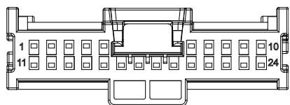
Con1 - Insert contacts side view (to DynaGATE 10-14)
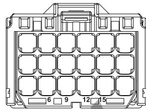
Con2 - Insert contacts side view (ITxPT)
Connections:
| Con2 Pin (ITxPT) | Con1 Pin (to DynaGATE 10-14) | ITxPT Signal | DynaGATE 10-14 function |
| 1 | 10 | Low battery | Isolated Digital Input 1 |
| 2 | 9 | Odometer | Isolated Digital Input 2 |
| 3 | 8 | Doors 1 open | Isolated Digital Input 3 |
| 4 | 7 | Doors 2 open | Isolated Digital Input 4 |
| 5 | 6 | Doors 3 open | Isolated Digital Input 5 |
| 6 | 24 | Doors 4 open | Isolated Digital Input 6 |
| 7 | 23 | Doors 5 open | Isolated Digital Input 7 |
| 8 | 22 | Doors 6 open | Isolated Digital Input 8 |
| 9 | reserved | ||
| 10 | reserved | ||
| 11 | reserved | ||
| 12 | reserved | ||
| 13 | reserved | ||
| 14 | 21 | AnyDoorOpen | Isolated Digital Input 9 |
| 15 | 1 | Awake request | Isolated Digital Output 1A |
| 16 | 20 | Stop request | Isolated Digital Input 10 |
| 17 | 19 | Full power available | Isolated Digital Input 11 |
| 18 | reserved |
Note: ITxPT requires one common ground linked to vehicle chassis. The user must assume responsibility for connecting the isolated grounds (refer to 8.1.2) to common ground
8.2 COM connectors
The DynaGATE 10-14 has up 4x RS-232/422/485 protected and isolated serial ports on the rear side, according to the product variants:
- 2x RS-232/422/485 (COM0 and COM1) for product variants -x1, -x3, -x4, -x5, -x7
- 4x RS-232/422/485 (COM0 to COM3) for product variants -x9
The RS-232/485/422 serial modes are software-controlled. For more information, refer to: "DynaGATE 10-14 EL Software Manual".
8.2.1 Termination resistors and fail-safe receivers
The serial ports are isolated, surge protected, with termination resistors and fail-safe receivers.
The DynaGATE 10-14 includes software-controlled 120 Ohm termination resistors for the RS-485 or RS-422 serial modes. For more information, refer to: "DynaGATE 10-14 EL Software Manual".
Termination resistors are used to reduce reflections when long cables are used at high baud rates.
Reflections can significantly reduce the signal level and introduce 'dead spots' increasing the system's susceptibility to noise and reduce reliability.
To avoid reflections a resistor which matches the impedance of the cable (approx. 120 Ohm for twisted pairs) should be placed across the ends of the cable. The DynaGATE 10-14 termination resistors should be enabled if the system is connected to the end of the cable.
In RS-485 connections there are times when all the line drivers are disabled, and the D+ and D- signals are either floating or pulled together by the terminating resistors. Most modern RS-485 receivers (including those on the DynaGATE 10-14) are designed to cope with this condition but some legacy devices may see this as a break condition or start to oscillate. In these situations, a pull-up resistor between the D+ line and +5 V and between the D- line and 0 V should be used to bias the lines to a '1' state.
8.2.2 COM0 and COM1 connectors specifications (for all product variants)
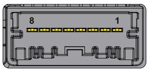
Connector Layout:
Connector Specifications:
- Mini50 Unsealed Header
- Single Row, 8 Circuits
- Polarization Option A
Black
Mating Connector Specifications:
- Receptacle:
o Mini50 Unsealed Receptacle
Single Row, 8 Circuits
- Polarization Option A
。 Black
Crimp Terminal:
- Mini50 Unsealed Crimp Terminal
L-Grip
Tin plated
Example:
Manufacturer: Molex
Part number Receptacle: 34791-0080
Part number Crimp Terminal: 560023-0448
Connector Pinout in RS-232 mode (pins not listed are reserved):
| Pin # | Signal | Type | Description |
| 1 | Y1/D1+_TERM | O | TXD1 |
| 2 | Z1/D1-_TERM | O | RTS1 |
| 3 | A1_TERM | I | RXD1 |
| 4 | B1_TERM | I | CTS1 |
| 5 | GND_ISO | P | Ground Reference |
| 6 | GND_ISO | P | Ground Reference |
Connector Pinout in RS-422 mode (pins not listed are reserved):
| Pin # | Signal | Type | Description |
| 1 | Y1/D1+_TERM | O | Y1(OUT+) |
| 2 | Z1/D1-_TERM | O | Z1(OUT-) |
| 3 | A1_TERM | I | A1(IN+) |
| 4 | B1_TERM | I | B1(IN-) |
| 5 | GND_ISO | P | Ground Reference |
| 6 | GND_ISO | P | Ground Reference |
Connector Pinout in RS-485 mode (pins not listed are reserved):
| Pin # | Signal | Type | Description |
| 1 | Y1/D1+_TERM | I/O | D1+ |
| 2 | Z1/D1-_TERM | I/O | D1- |
| 5 | GND_ISO | P | Ground Reference |
| 6 | GND_ISO | P | Ground Reference |
8.2.3 COM2 and COM3 connectors specifications (only for product variants -x9)
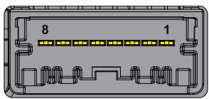
Connector Layout:
Connector Specifications:
- Mini50 Unsealed Header
- Single Row, 8 Circuits
- Polarization Option A
Black
Mating Connector Specifications:
- Receptacle:
o Mini50 Unsealed Receptacle
Single Row, 8 Circuits
- Polarization Option A
。 Black
Crimp Terminal:
- Mini50 Unsealed Crimp Terminal
L-Grip
Tin plated
Example:
Manufacturer: Molex
Part number Receptacle: 34791-0080
Part number Crimp Terminal: 560023-0448
Connector Pinout in RS-232 mode (pins not listed are reserved):
| Pin # | Signal | Type | Description |
| 1 | Y1/D1+_TERM | O | TXD1 |
| 2 | Z1/D1-_TERM | O | RTS1 |
| 3 | A1_TERM | I | RXD1 |
| 4 | B1_TERM | I | CTS1 |
| 5 | GND_ISO | P | Ground Reference |
| 6 | GND_ISO | P | Ground Reference |
Connector Pinout in RS-422 mode (pins not listed are reserved):
| Pin # | Signal | Type | Description |
| 1 | Y1/D1+_TERM | O | Y1(OUT+) |
| 2 | Z1/D1-_TERM | O | Z1(OUT-) |
| 3 | A1_TERM | I | A1(IN+) |
| 4 | B1_TERM | I | B1(IN-) |
| 5 | GND_ISO | P | Ground Reference |
| 6 | GND_ISO | P | Ground Reference |
Connector Pinout in RS-485 mode (pins not listed are reserved):
| Pin # | Signal | Type | Description |
| 1 | Y1/D1+_TERM | I/O | D1+ |
| 2 | Z1/D1-_TERM | I/O | D1- |
| 5 | GND_ISO | P | Ground Reference |
| 6 | GND_ISO | P | Ground Reference |
8.3 Ethernet connectors
The DynaGATE 10-14 has up to 4x Ethernet (GbE) connectors, according to the product variants:
- 2x GbE connectors for product variants -x1, -x3, -x4, -x5, -x9
- 4x GbE connectors for product variants -x7
The connectors are available on the rear side.
8.3.1 Ethernet specifications
| Feature | Description |
| Network Standard | Compliant with IEEE 802.3 (10BASE-T, 100BASE-TX, and 1000BASE-T) specifications |
| Speeds | 10 Mbps, 100 Mbps, and 1000 Mbps |
8.3.2 Ethernet connectors specifications
Connector Layout:
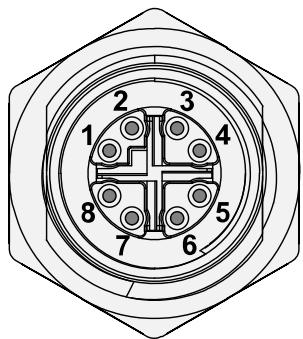
Connector Specifications:
- Panel-mount; M12 series
Gender: Female - Type: X-Coded; 8-pin
Mating Connector Specifications:
Cable-Mount; M12 series
Gender: Male
- Type: X-Coded; 8-pin
- Example of cable: Manufacturer: Metz Connect Part Number: 142M2X10005 (or equivalent)
Connector Pinout:
| Pin # | Signal | Type | Description | Male RJ45 Pin # |
| 1 | TX+_D1 | O | Transmit Data + | 1 |
| 2 | TX-_D1 | O | Transmit Data - | 2 |
| 3 | RX+_D2 | I | Receive Data + | 3 |
| 4 | RX-_D2 | I | Receive Data - | 6 |
| 5 | BI+_D4 | I/O | Bidirectional Data + | 7 |
| 6 | BI-_D4 | I/O | Bidirectional Data - | 8 |
| 7 | BI-_D3 | I/O | Bidirectional Data - | 5 |
| 8 | BI+_D3 | I/O | Bidirectional Data + | 4 |
8.4 CAN connectors
The DynaGATE 10-14 has 2x CAN (Controller Area Network) ports on the rear side. They are compliant with CAN Specification 2.0, Parts A and B, and CAN FD (flexible data-rate). The ports are isolated and protected against surge.
8.4.1 Termination resistors
The DynaGATE 10-14 includes software-controlled 120 Ohm termination resistors.
For more information, refer to: "DynaGATE 10-14 EL Software Manual".
8.4.2 CAN0 and CAN1 connectors specifications

NOTICE
To make sure that the connection keeps the ITxPT compliance, use the optional accessory 99ACC-70000-A0003: CAN ITxPT cable (described on the next page).
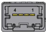
Connector Layout:
Connector Specifications:
- Mini50 Unsealed Header
- Single Row, 4 Circuits
- Polarization Option A
Black
Mating Connector Specifications:
Receptacle:
- Mini50 Unsealed Receptacle
Single Row, 4 Circuits
o Polarization Option A
。 Black
Crimp Terminal:
o Mini50 Unsealed Crimp Terminal
L-Grip
Tin plated
Example:
Manufacturer:Molex
Part number Receptacle: 34791-0040
Part number Crimp Terminal: 560023-0448
8.4.3 99ACC-70000-A0003: CAN ITxPT cable
Con1: Mini50 Unsealed Receptacle, Single Row, 4 Circuits, Polarization Option A, Black
Con2:2,5MM BU-GEH Housing, 4 Circuits, Black
Length: 50~cm
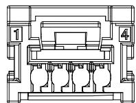
Con1 - Insert contacts side view (to DynaGATE 10-14)
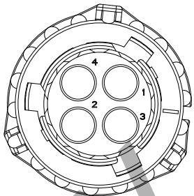
Con2 - Insert contacts side view (ITxPT)
Connections:
| Con2 Pin (ITxPT) | Con1 Pin (to DynaGATE 10-14) | ITxPT Signal | DynaGATE 10-14 function |
| 1 | 2 | CAN High | CAN data + |
| 2 | 1 | CAN Low | CAN data - |
| 3 | 3 | Option CAN ground | Ground |
| 4 | Not used |
8.5 GNSS
The DynaGATE 10-14 has two GNSS solutions, according to the product variants:
- u-blox NEO-M9V receiver with UDR and ADR for product variants -x1, -x3, -x5, -x7, -x9
- u-blox ZED-F9P receiver with RTK for product variants -x4
The antenna connector is placed on the rear side.
8.5.1 GNSS specifications (product variants -x1, -x3, -x5, -x7, -x9)
| Feature | Description |
| Receiver type | 92-channel u-blox M9 engine GPS L1 C/A, QZSS L1 C/A/S, GLONASS L1OF BeiDou B1I (1561.098 MHz) only, Galileo E1B/C SBAS L1 C/A: WAAS, EGNOS, MSAS, GAGAN |
| Navigation update rate | Up to 50 Hz (4 concurrent GNSS) |
| Horizontal position accuracy | 1.5 m CEP (with SBAS) 2.0 m CEP (without SBAS) |
| ADR position error | 2% of distance traveled without GNSS |
| UDR position error | 10% of distance traveled without GNSS (duration < 60 s) |
| Acquisition1 | Cold start: 24 s Aided start: 2 s Hot start: 2 s |
| Sensitivity1 | Tracking & Nav.: -160 dBm Reacquisition: -159 dBm Cold start: -148 dBm Hot start: -158 dBm |
1 For default mode: GPS/GLONASS/BeiDou/Galileo + SBAS/QZSS
8.5.2 GNSS specifications (product variants -x4)
| Feature | Description | |
| Receiver type | 184-channel u-blox F9 engineGPS L1C/A L2C, GLO L1OF L2OF,GAL E1B/C E5b, BDS B1I B2I,QZSS L1C/A L1S L2C, BAS L1C/A | |
| Navigation update rate | RTK | up to 20 Hz1 |
| Position accuracy2 | RTK | 0.01 m + 1 ppm CEP |
| Convergence time2 | RTK | < 10 s |
| Acquisition | Cold start: | 24 s |
| Aided start: | 2 s | |
| Hot start: | 2 s | |
| Sensitivity | Tracking & Nav.: | -167 dBm |
| Cold start: | -148 dBm | |
| Hot start: | -157 dBm | |
| Reacquisition: | -160 dBm | |
1 The highest navigation rate can limit the number of supported constellations
Depends on atmospheric conditions, baseline length, GNSS antenna, multipath conditions, satellite visibility, and geometry
8.5.3 GNSS antenna - Installation guidelines
- Do not co-locate or operate the antenna in conjunction with another antenna or transmitter
- Do not install the antenna inside metal cases.
8.5.4 GNSS antenna connector specifications
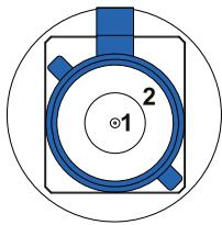
Connector Layout:
Connector Pinout:
| Pin # | Description |
| 1 | Male inner pin contact |
| 2 | Female connector body |
Connector Specifications:
- FAKRA connector
Code: C-Blue
Gender: Male panel mount
Mating Connector Specifications:
- FAKRA connector
Code: C-Blue
Gender: Female
8.6 Wi-Fi and Bluetooth (all product variants but: -x1)
The DynaGATE 10-14 integrates a 802.11 a/b/g/n/ac (2.4 GHz, 5 GHz) - BLE5 (2.4 GHz) module. The antenna connector is placed on the rear side.
8.6.1 Wi-Fi and Bluetooth specifications
| Feature | Description |
| RF Spec | ·Wi-Fi - 802.11 a/b/g/n/ac (2.4 GHz, 5 GHz @ 20/40/80 MHz) ·BT/BLE5 |
| Interfaces | ·WLAN SDIO 3.0 ·BT UART ·BT PCM/I2S ·LTE Coexistence UART (WCI) ·Low frequency 32.768 kHz sleep clock ·Single Antenna port, 50 Ω ·Control signals |
| Support Data Rate | ·802.11a (5 GHz): 6, 9, 12, 18, 24, 36, 48, 54 Mbps ·802.11b (2.4 GHz): 1, 2, 5.5, 11 Mbps ·802.11g (2.4 GHz): 6, 9, 12, 18, 24, 36, 48, 54 Mbps ·802.11n (2.4 GHz / 5 GHz): ·20 MHz BW: Up to 72.2 Mbps using short GI (MCS0-7) ·40 MHz BW: Up to 144.4 Mbps using short GI (MCS0-7) ·802.11ac (5 GHz): HT20 (MCS0-8), VHT40 (MCS0-9), VHT80 (MCS0-9) |
| Frequency Bands and related max RF Transmitted Power | Bluetooth: ·2400 MHz to 2483.5 MHz < 9dBm WiFi b/g/n/ac 2.4 GHz band: ·2412 MHz to 2472 MHz < 17.5 dBm WiFi a/n/ac 5 GHz bands: ·U-NIL-1: 5150 MHz to 5250 MHz < 13.9 dBm ·U-NIL-2A: 5250 MHz to 5350 MHz < 15 dBm ·U-NIL-2C, U-NIL-2e: 5470 MHz to 5725 MHz < 15 dBm ·U-NIL-3: 5725 MHz to 5825 MHz < 15 dBm |
| Data Standard | IEEE 802.11a/b/g/n/ac |
| Modulation | BPSK, QPSK, CCK, 16QAM, 64QAM, 256QAM |
8.6.2 Wi-Fi/Bluetooth antenna - Installation guidelines
Do not install the antenna inside metal cases.
8.6.3 Wi-Fi/Bluetooth antenna connector specifications

Connector Layout:
Connector Pinout:
| Pin # | Description |
| 1 | Male inner pin contact |
| 2 | Female connector body |
Connector Specifications:
- FAKRA connector
Code: I-Beige
Gender: Male panel mount
Mating Connector Specifications:
- FAKRA connector
Code: I-Beige
Gender: Female
8.7 Cellular Modem (all product variants but: -x1)
The DynaGATE 10-14 integrates a worldwide LTE Cat 4 module.
The antenna connectors are placed on the rear side.
8.7.1 Cellular Modem specifications
| Feature | Description |
| Key Features | LTE Cat 4 module optimized for broadband IoT/M2M applicationsMaximum data rates up to 150 Mbps downlink and 50 Mbps uplinkWorldwide LTE and UMTS/HSPA+ coverageMIMO technology |
| Frequency Bands | WCDMA: 900 (B8), 2100 (B1)E-UTRA LTE FDD 2100 (B1) / 1800 (B3) / 2600 (B7) / 900 (B8) / 800 (B20) / 700 (B28)E-UTRA LTE TDD 2600 (B38) / 2300 (B40) |
| Data Transmission(Max.) | LTE-FDD data rate (Mbps) 150 (DL)/ 50 (UL)LTE-TDD data rate (Mbps) 130 (DL)/ 30 (UL)DC-HSDPA+ data rate (Mbps) 42 (DL)/ 5.76 (UL)WCDMA data rate (kbps) 384 (DL)/ 384 (UL) |
| RF Power | 0.25 W (24 dBm +1,7/-3,7 dB) - Class 3 @ WCDMA0.2 W (23 dBm ± 2,7 dB) - Class 3 @ E-UTRA LTE |
| Main and RX-diversityAntenna Requirements | VSWR ≤ 2Efficiency > 30%Max Input Power 50 WInput Impedance 50 ΩCable Insertion Loss < 1 dB : LB (< 1 GHZ)< 1.5 dB : MB (1-2.3 GHz)< 2 dB : HB (> 2.3 GHz) |
8.7.2 Cellular Modem antennas - Installation guidelines
The antenna must be installed such that it keeps a distance from persons greater than 20~cm , and must not be co-located or operating in conjunction with any other antenna or transmitter.
Do not install the antenna inside metal cases.
8.7.2.1 LTE single antenna operation notes
Single LTE antenna operation can be supported; however, typically, wireless carriers (Mobile Network Operators) impose restrictions. Consult with your carrier before considering single LTE antenna usage.
For optimum performance of the cellular interface, Eurotech recommends the use of both main and diversity antenna connectors.
If the diversity antenna is not used/ connected, Eurotech recommends to disable the diversity function.
8.7.3 Cellular Modem antennas connectors specifications
Specifications are the same for both antenna connectors:
- MAIN antenna connector
- DIV antenna connector
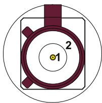
Connector Layout:
Connector Pinout:
| Pin # | Description |
| 1 | Male inner pin contact |
| 2 | Female connector body |
Connector Specifications:
- FAKRA connector
Code: D-Bordeaux
Gender: Male panel mount
Mating Connector Specifications:
- FAKRA connector
Code: D-Bordeaux
Gender: Female
9 OTHER INTERFACES IN DETAIL
The interfaces availability depends on the product variant. For more information, refer to:"Technical specifications" on page 19.
This chapter gives the following information:
9.1 TPM 67
9.2 Watchdog 67
9.3RTC and tamper detection 67
9.1 TPM
The DynaGATE 10-14 includes a TPM 2.0 hardware module: Infineon SLB9670. This is connected to the CPU via an SPI interface.
For more information, refer to:"DynaGATE 10-14 EL Software Manual".
9.2 Watchdog
The DynaGATE 10-14 uses the CPU's internal watchdog to provide a product reset when the software becomes unresponsive.
For more information, refer to:"DynaGATE 10-14 EL Software Manual".
9.3 RTC and tamper detection
9.3.1 The RTC Devices
For more information, refer to:"DynaGATE 10-14 EL Software Manual".
9.3.2 The RTC backup supercap
The DynaGATE 10-14 includes a non-removable RTC backup supercap. The RTC backup supercap can keep the timestamps for at least 10 days when the DynaGATE 10-14 is powered OFF.
Note: This is only valid above -25 °C. Below this value, the supercap retention time will be lower.
IMPORTANT: If the supercap completely discharges while the DynaGATE 10-14 is OFF, the RTC date and time will reset (default date and time is 1st January 2000, 00:00).
Date and time will need to be set again, either manually, or through NTP.
9.3.3 The tamper detection
When the Service Panel cover (or the case) is opened, this event is recorded by the RTC timestamp register.
For more information, refer to:"DynaGATE 10-14 EL Software Manual".
The tamper detection function is active also while the DynaGATE 10-14 is OFF.
IMPORTANT: If the supercap completely discharges while the DynaGATE 10-14 is OFF, any tamper events which were recorded since the product was last powered OFF will be lost. Instead, the security log will record that time was lost.
10 MECHANICAL SPECIFICATIONS
This chapter gives the following information:
10.1 Product enclosure specifications 69
10.2 Product mechanical dimensions 69
10.1 Product enclosure specifications
The product enclosure has the following specifications:
Material: Aluminum
Color: Black
Finish: Anodized
10.2 Product mechanical dimensions
The product has the following mechanical dimensions: 270 × 123 × 51 ~mm (WxDxH) - Excluded Connectors.
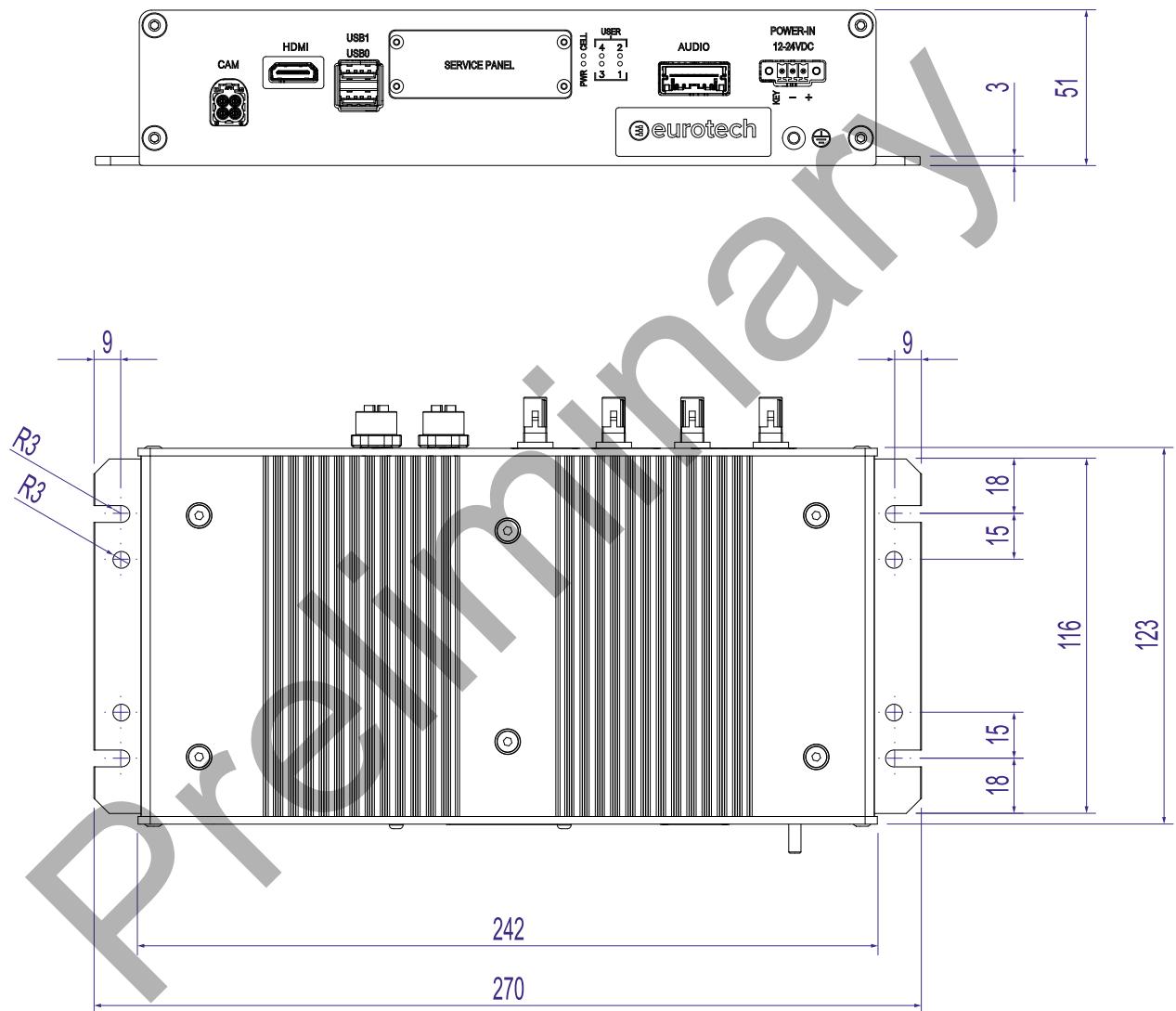
Fig. 10 - DynaGATE 10-14 mechanical dimensions (in mm)
11 PRODUCT INSTALLATION
This chapter gives the following information:
11.1 Introduction 71
11.2 How to install the product 71
11.1 Introduction
The product is intended for professional use and must be installed by qualified personnel only. The product must be installed in a secured location, accessible to authorized personnel only (for example in a cabinet / technical compartment).
The product is intended to be installed horizontally on a plane surface.

NOTICE
Always use the Earth connection terminal to connect the product to an earth point in the installation. For more information, refer to: "Earth connection terminal" on page 49.
11.2 How to install the product
To install the product, complete this procedure:
- Make sure that the place where you install the product is a plane surface
- Refer to "Mechanical specifications" on page 68
- Use the slots/holes available on the two lateral mounting brackets of the product
- Add all the necessary hardware to safely fasten the product in place according to your installation requirements. Use 4x M5 screws.
Material, type, and length of the screws, and the maximum torque applicable, depend on your installation requirements.
The mounting brackets specifications are the following:
- Thickness: 3 mm
- Material: EN AW 6060 T5 Extruded; Finish: Black Anodizing.
For more information, refer to: https://www.eurotech.com/support.
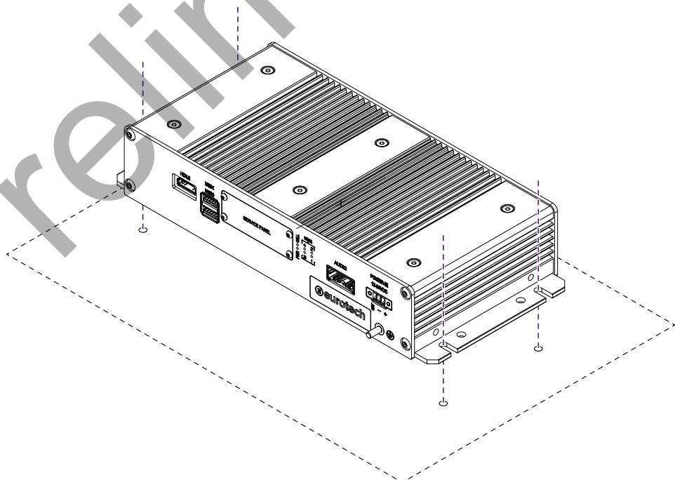
Fig. 11 - Example of how to install the product
12 PRODUCT POWER REQUIREMENTS
This chapter gives the following information:
12.1 Important note 73
12.2 Power specifications 73
12.3 Power IN connector specifications 73
12.4 How to supply power and turn ON the product 74
12.5 Supercap-based power backup feature 76
12.6Turning OFF the product 76
12.7 Reducing the power consumption of the product 76
12.8 How to reset the product 76
12.1 Important note
This product does not have an ON/OFF switch.
The Power IN connector is the disconnecting means from the power supply network. Make sure that you can always reach the Power IN connector immediately.
12.2 Power specifications
The power input is protected against: surge, noise, reverse polarity, over-voltage.
| Specification | Description |
| Power Supply | Nominal: 12 and 24 V DC; Range: 9 to 35 V DC with Transient Protection and Vehicle Ignition Sense |
| Power Consumption | Typical: 10 W; Sleep < 2.5 W |
12.3 Power IN connector specifications

NOTICE
The Power IN connector is NOT protected against short circuit. Always include an external fuse to protect the product.

NOTICE
To make sure that the connection keeps the ITxPT compliance, use the optional accessory 99ACC-70000-A0004: Power ITxPT cable (described on page 48).
The Power IN connector has the following specifications:
Connector Layout:
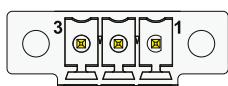
Connector Specifications:
- Base strip, Header
Gender: Male
Type: 3-pin, 3.5mm pitch
Mating Connector Specifications:
- Pluggable screw terminal block
Gender: Female - Type: 3-pin, 3.5 mm pitch
Example:
Manufacturer: Phoenix Contact
Part Number: MC 1,5/3-STF-3,5 - 1847068 (or equivalent)
Connector Pinout:
| Pin # | Signal | Type | Description |
| 1 | VIN + | P | Positive power supply input |
| 2 | VIN - | P | Negative power supply input |
| 3 | IGN_IN | P | KEY Signal |
12.4 How to supply power and turn ON the product
12.4.1 Power supply safety instructions

WARNING
Risk of electric shock. Failure to supply power correctly could result in death or serious injury, and could damage the equipment or other property.
Refer to "What to do before you supply power to the product" below.
12.4.1.1 What to do before you supply power to the product
Before you supply power to the product, obey the following safety instructions:
- Make sure that you have understood any instructions for safety, installation, and for operation
Make sure that your hands are dry - Make sure that all the cables to use:
meet the product requirements and comply with the relevant standards and regulations
are in good condition
are placed with care
are not placed where they may be trampled or compressed
- Make sure that all power-points and plugs:
are in good condition
are not overloaded
- Make sure that the product has a proper grounding connection
- Make sure that the power supply source meets the product requirements and complies with the relevant standards and regulations
- Make sure that the product installation is made correctly and in compliance with the relevant standards and regulations
- Make sure that you supply power only after the product installation is completed.
If you have questions about these instructions, refer to: https://www.eurotech.com/support.
12.4.2 How to supply power and turn ON the product
Note: Refer also to "Supercap-based power backup feature" on the facing page.
Note: The screw terminal block of the AC/DC Power Supply Adapter (refer also to "Optional accessories" on page 21) has the KEY pin connected to the "VIN +" pin. If you use this AC/DC Power Supply Adapter, the status of the DIP-switch slider 1 is not applicable:
- To turn ON the DynaGATE 10-14, connect the AC/DC Power Supply Adapter
To supply power and turn ON the DynaGATE 10-14, complete this procedure:
-
Setup a DC power source that:
-
Meets the DynaGATE 10-14 power requirements
-
Delivers minimum power of 65 W
-
Check the input voltage (VIN) as close as possible to the Power IN connector. This is to compensate for any cable losses, caused by cable length and other cable characteristics
- Make sure that the DC power source is OFF
- Setup an external 3 A fuse on the line coming from the positive terminal of the DC power source
- Connect the DC power source terminals to the Power IN connector:
"VIN+" to Pin 1
"VIN - " to Pin 2
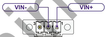
- Turn ON the DC power source.
According to the status of DIP switch slider SW1 (available in the Service Panel, refer also to "DIP switch definitions" on page 38), one the following options will occur:
- If SW1 is OFF, the DynaGATE 10-14 will turn ON. The PWR LED will turn ON.
- If SW1 is ON, the DynaGATE 10-14 will remain OFF.
To turn ON the DynaGATE 10-14, connect Pin 3 (IGN_IN/ KEY Signal) of the Power IN connector to "VIN +". The PWR LED will turn ON.
To keep the DynaGATE 10-14 ON, make sure that Pin 3 remains connected to "VIN +". When connecting Pin 3 to "VIN +", keep it connected for at least 10 seconds.
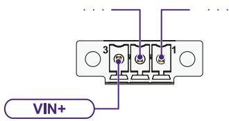
12.5 Supercap-based power backup feature
The DynaGATE 10-14 is equipped with supercap-based power backup feature which can power the product for up to 2 minutes (depending on the CPU load and the active peripherals) after the power is removed. This feature enables a safe shutdown.
After 2 minutes have passed, even if the product appears to be OFF, some internal electronics remain powered until the supercap is fully discharged, this may take several minutes
After the bootstrap, to prevent data loss from unexpected power failure, some interfaces may not be immediately available until the supercap is fully charged.
When a power failure is detected during normal operation (supercap is fully charged), the product immediately turns OFF some interfaces. Other interfaces are given time to safely disconnect, save the system state, and unmount the file systems.
For more information, refer to:"DynaGATE 10-14 EL Software Manual".
12.6 Turning OFF the product
To turn OFF the DynaGATE 10-14, execute either a poweroff or shutdown now command.
The DynaGATE 10-14 will respond as follows, regardless of the SW1 status:
- If the KEY Signal (IGN_IN) is ON, the DynaGATE 10-14 turns OFF and restarts immediately
- If the KEY Signal (IGN_IN) is OFF, the DynaGATE 10-14 turns OFF and remains OFF until the IGN_IN comes ON again
IMPORTANT: After you executed a poweroff or shutdown now command, the supercap remains in charge until you disconnect the power supply source. Handle the DynaGATE 10-14 with care.
For more information, refer to:
- "DIP switch definitions" on page 38
"Supercap-based power backup feature" above
Software services are available to initiate a software shutdown when the power supply source is disconnected, or when the KEY Signal (IGN_IN) is turned OFF. For more information, refer to:"DynaGATE 10-14 EL Software Manual".
12.7 Reducing the power consumption of the product
To reduce the power consumption of the DynaGATE 10-14, turn OFF the radio interfaces and disable unnecessary services.
12.8 How to reset the product
12.8.1 Hardware reset
To trigger a hardware reset of the DynaGATE 10-14, push the reset button available in the Service Panel.
12.8.2 Software reset
The product can be reset through software commands. For more information, refer to:"DynaGATE 10-14 EL Software Manual".
13 PRODUCT MAINTENANCE
This chapter gives the following information:
13.1 How to maintain the product 78
13.1 How to maintain the product

WARNING
Before you start product maintenance, always remove the power supply. Failure to remove the power supply could result in death or serious injury.
Periodically maintain the product to examine its integrity and to ensure its proper operation. A maximum inspection period of 2 years is recommended, though the installer must assess the impact of environmental conditions when selecting an appropriate inspection regime.
To maintain the product, complete this procedure:
- Obey the instructions contained in the section "Safety-related information" on page 7
- Remove the power supply from the product:
a. Make sure that your hands are dry
b. Turn OFF all the power supply sources
c. Disconnect all the cables
d. Make sure that all the circuits are discharged
- Examine the product and cabling:
a. Make sure that the product is not damaged
b. Make sure that the LED indicators are visible and not damaged
c. Make sure that the external cabling is not damaged or frayed
-
Clean the product:
-
To remove the dust, use a dry lint-free cloth
- To remove the dirt, use water-based non-flammable cleaning products
- To dry the product, use a dry lint-free cloth
-
Do not use detergents, aerosol sprays, solvents or abrasive sponges
-
Examine the product installation:
a. Make sure that all the locking parts (for example: screws, bolts, nuts) are securely fastened
b. Make sure that the product is installed correctly (refer also to "Product installation" on page 70)
c. Make sure that the product is grounded correctly (refer also to "Earth connection terminal" on page 49).
NOTES
HEADQUARTERS
Via Fratelli Solari, 3/a
33020 Amaro (UD) - Italy
Email: welcome@eurotech.com
Web: https://www.eurotech.com
Tel: +39 0433.485.411
Fax: +39 0433.485.499

CONTACT US
https://www.eurotech.com/contact-us

SUPPORT PORTAL
https://support.eurotech.com

DOWNLOAD AREA
https://www.eurotech.com/download

RMA
https://www.eurotech.com/support/rma