USER MANUAL IH 3 TB 342C VALBERG
This product has a 2-year warranty as of the date of purchase*, covering any fault resulting from a manufacturing or material defect. This warranty does not cover defects or damage resulting from incorrect installation, improper use or abnormal wear of the appliance.
*upon presentation of the sales receipt.
CONDITION DE GARANTIE
FR
flowchart
graph TD
    A["6"] --> B["8"]
    A --> C["8"]
    A --> D["8"]
    A --> E["99"]
    B --> F["负"]
    C --> G["+"]
    D --> H["+"]
    E --> I["B"]
    E --> J["10"]
    E --> K["11"]
    E --> L["12"]
    F --> M["7"]
    G --> N["8"]
    H --> O["9"]
    I --> P["10"]
    J --> Q["11"]
    K --> R["12"]
Thanks!
Thank you for choosing this VALBERG product. Chosen, tested and recommended by ELECTRO DEPOT, the products of the VALBERG brand are easy to use, reliable and of an impeccable standard. Thanks to this appliance, you can be sure that each use will bring you satisfaction.
Welcome to ELECTRO DEPOT.
Visit our website: www.electrodepot.fr
www.electrodepot.be

Preview of the appliance
Description of the appliance

Using the appliance
Installation
Operation instructions
Heat Settings

Useful information
Cleaning and maintenance
Hints and Tips
Failure Inspection for induction hob
The instructions are also available on the site http://www.electrodepot.fr/sav/notices/ http://www.electrodepot.fr/sav/notices
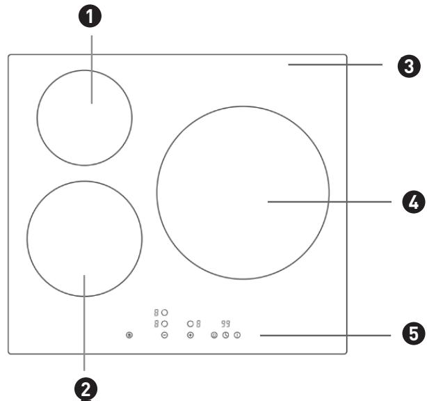
Description of the appliance
1 1300/1500W Cooking Zone
2 1900/2200W Cooking Zone
3 Glass plate
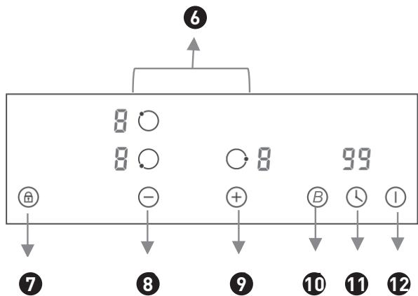
Control Panel
6 Cooking Zone selection button
7 Child Lock control button Cooking
8 Heating level/Timer "-" button
9 Heating level/Timer "+" button
4 2300/3000W Cooking Zone
5 Control panel
10 Booster control button
11 Timer selection button
12 ON/OFF button
NOTE:
Product diagrams in the manual for reference only, there might be slightly difference due to continually product improvements.
Before using your New Hob
- Read this guide, taking special note of the ‘Safety Warnings’ section.
- Remove any protective film that may still be on your new electric hob.
Installation
NOTE:
The appliance must be installed and connected in accordance with current regulations. After unpacking the appliance, ensure there is no visible damage. If it has been damaged during transit, DO NOT USE, contact where you buy immediately.
Selection of installation equipment
- Cut out the work surface according to the sizes shown in the drawing.
- For the purpose of installation and use, a minimum of 5 cm space shall be preserved around the hole.
- Be sure the thickness of the work surface is at least 30mm. Please select heat-resistant and insulated work surface material to avoid larger deformation caused by the heat radiation from the hotplate. As shown below (measure by unit: mm):
NOTE:
The safety distance between the sides of the hob and the inner surfaces of the worktop should be at least 3 mm.
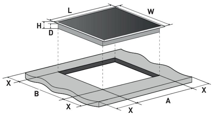
| Model | L | W | H | D | A | B | X |
| 60cm induction hob | 590 | 520 | 56 | 48 | 555+5-0 | 495+5-0 | 50 min |
Under any circumstances, make sure the electric hob is well ventilated and the air inlet and outlet are not blocked. Ensure the electric hob is in good work state. As shown below:
NOTE:
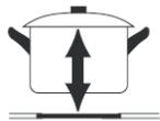
The safety distance between the hotplate and the cupboard above the hotplate should be at least 760 mm.
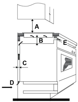
A(mm)
760mm
B(mm)
50mm minimal
C(mm)
20mm minimal
D
Air intake
E
Air exit 5mm
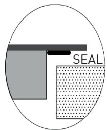
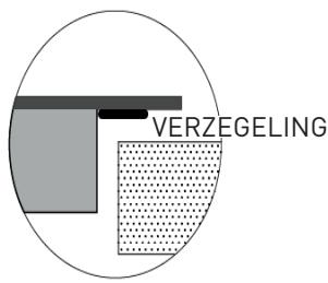
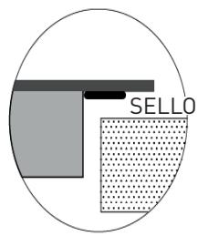
Installing the foam gasket
- Before inserting the hob into the opening in the kitchen worktop, the supplied foam gasket (in a plastic bag) must be attached to the lower side of the ceramic glass.
WARNING:
Do not install the hob without the foam gasket!
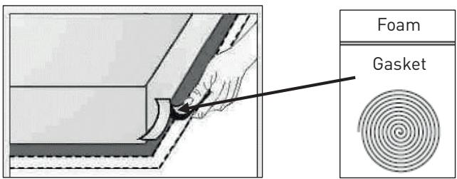
The gasket should be attached to the hob in the following method:
- Remove the protective film from the gasket.
- Then attach the gasket to the lower side of the glass, next to the edge.
- The gasket must be attached along the entire length of the glass edge and should not overlap at the corners.
- When installing the gasket, make sure that the glass does not come into contact with any sharp objects.
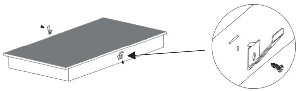
Before locating the fixing brackets
The unit should be placed on a stable, smooth surface (use the packaging). Do not apply force onto the controls protruding from the hob.
- Easy Fit kits
There is one easy fit kits package for each hob, include fixing clips and screws. Find the easy fit kit package first.
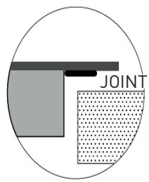
- Fix clips to hob
Insert the fixing clips into fixing holes reserved on 2 sides of housing, fix clip to housing with screw, then insert hob into cabinet/work surface.
natural_image
Diagram showing a rectangular panel with a magnified inset of its edge detail (no text or symbols)
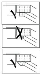
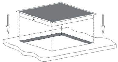
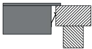
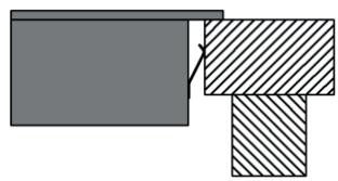
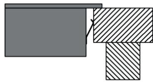
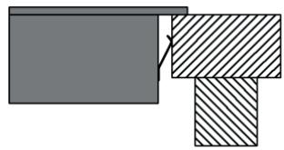
- Fix hob to cabinet
Insert the hob into the cabinet/work surface as below diagrams, the mounted clips on the sides can secure your hob sturdily.
natural_image
Diagram of a layered structure with arrows indicating force or movement, no text or symbols present
natural_image
Pure geometric diagram showing two overlapping rectangles with diagonal hatching (no text or symbols)
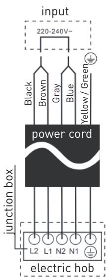
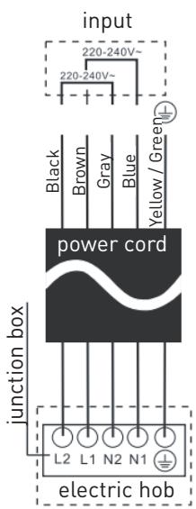
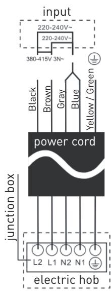
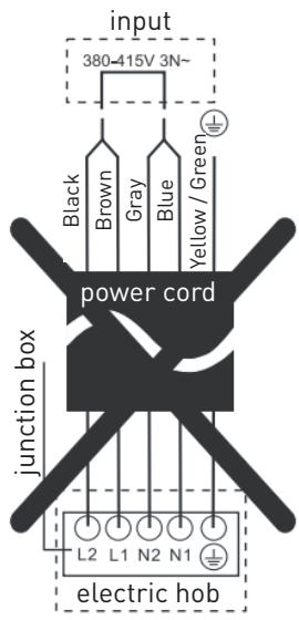
Connecting the hob to the mains power supply
The power supply should be connected in compliance with the relevant standard, or a single-pole circuit breaker.
The appliance has a large power rating and must be connected to electricity by a Qualified Electrician.
Notes :
- If the cable is damaged or needs replacing, this should be done by an after-sales technician using the proper tools, so as to avoid any accidents.
- If the appliance is being connected directly to the mains supply, an omni polar circuit breaker must be installed with a minimum gap of 3mm between the contacts.
- The installer must ensure that the correct electrical connection has been made and that it complies with safety regulations.
- The cable must not be bent or compressed.
- The cable must be checked regularly and only replaced by qualified technician.
Cautions
- The hob must be installed by qualified personnel or technicians. Please never conduct the operation by yourself.
- The electric hob shall not be mounted to cooling equipment, dishwashers and rotary dryers.
- The electric hob shall be installed such that better heat radiation can be ensured to enhance its reliability.
- The wall and induced heating zone above the work surface shall withstand heat.
- To avoid any damage, the sandwich layer and adhesive must be heat resistant.
- A steam cleaner is not to be used.
- This electric hob can be connected only to a supply with system impedance no more than 0.427 ohm. In case necessary, please consult your supply authority for system impedance information.
NOTE:
For some of the models, there might applied with a power cord with plug. If so, you can directly plug in socket. Please keep power cord plug out after use.
For those model power cord without plug, the method of connections shown below.
Operation instructions
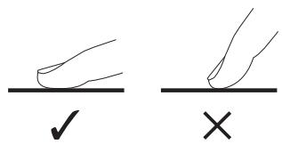
Using the Touch Controls
- The controls respond to touch, so you don't need to apply any pressure.
- Use the ball of your finger, not its tip.
- You will hear a beep each time a touch is registered.
- Make sure the controls are always clean, dry, and that there is no object (e.g. a utensil or a cloth) covering them. Even a thin film of water may make the controls difficult to operate.
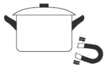
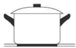
Choose the right Cookware
- Only use cookware with a base suitable for induction cooking. Look for the induction symbol on the packaging or on the bottom of the pan.
natural_image
Simple line drawing of a cooking pot with a U-shaped magnet nearby (no text or symbols)
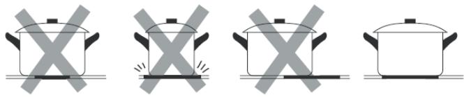
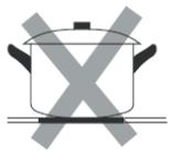
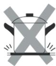
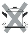
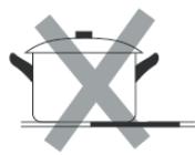
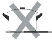
- Do not use cookware with jagged edges or a curved base.
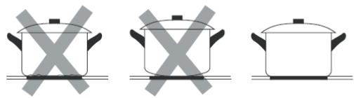
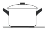
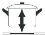
- Make sure that the base of your pan is smooth, sits flat against the glass, and is the same size as the cooking zone. If you use smaller pot efficiency could be less than expected. Always centre your pan on the cooking zone.
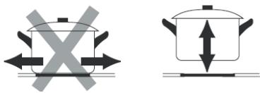
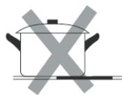
- Always lift pans off the hob – do not slide, or they may scratch the glass.
Suggested Pan dimensions for induction hob
The cooking zones are, up to a limit, automatically adapted to the diameter of the pan. However, the bottom of this pan is suggested to have a minimum of diameter according to the corresponding cooking zone. To obtain the best efficiency of your hob, please place the pan in the center of the cooking zone.
Base diameter of the pots:
| Cooking zone | Minimum (mm) | Maximum (mm) |
| 160mm | 140 | 160 |
| 180mm | 140 | 180 |
| 280mm | 230 | 280 |
Using your Hob
To start cooking
natural_image
Simple line drawing of a hand pointing upward with a circular symbol on the index finger (no text or labels)
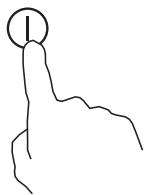
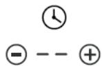
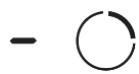
- After the hob be connected to electricity and power on. Press and hold the ON/OFF ① control button for about 3 seconds till you hear a “beep” to turn the hob on. Now the hob enters into Standby mode, all heat setting indicators and Timer setting indicators shows “-”
natural_image
Line drawing of a cooking pot on a stand (no text or symbols)
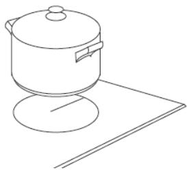
- Place a suitable pan on the cooking zone you wish to use.
- Make sure the bottom of the pan and the surface of the cooking zone are clean and dry.

natural_image
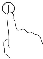
Simple line drawing of a hand holding a circular object with a dot at the top (no text or symbols)
- Set heating level of cooking zone
Before adjust heating level, need to touching the heating zone selection control button to select and active the cooking zone you wish to use. The heat setting indicator of the selected zone flashing when be active, then you could adjust its heat level by below:
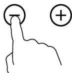
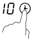
- Set heat setting by touching the ⏻ or Ⓕ button.
Notes:
- After connect to electricity, when power on, the buzzer of hob beeps once, all indicators light up for 1 second then go out.
- When the hob in Standby mode, if there is no practice within 1 minute, the electric hob will auto turn off, with buzzer beeps once.
- To turn on hob, press the ON/OFF control button and hold on for about 3 seconds; To turn it off, just need to press ON/OFF button again.
- The heat setting indicator of the selected zone flashing when adjusting. After adjusting, the number flashing for 5 seconds then stop flashing, then the setting is be confirmed.
To turn off hob
- You can turn the cooking zone off by adjust heat setting to level 0, which indicator shows “-”.
natural_image
Simple line drawing of a hand pointing upward with a circular symbol on the index finger (no text or labels)
- You can also turn the whole hob off by touching the ON/OFF Ⓘ control button.
Note: If there is power cut off during cooking, all setting will be cancelled.
Note: The cooling fan of induction hob will remain on for about 1 minute after the hob be turned off.
Using Booster Function-Induction Hob
You can use the “Booster” function to boost power of relevant cooking zone for a maximum power rating for 5 minutes. This function could reduce the cooking time, which convenience for cooking when in hurry!
To use booster function when hob is working, follows below:

natural_image
Simple line drawing of a hand holding a circular object with a dot at the top (no text or symbols)
-
Touch the heating zone selection control button to select the Cooking zone you want to use boost function.
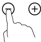
-
Adjust the cooking zone to a heating level by touching the heating level control button “+” or “-”.
- Touch the Booster function control button , the heating zone indicator will show "b" and flashing for 5 seconds then stop flashing, then Booster function be activated.
Note: After booster finish, the cooking zone will return to original setting.
Cancel the Booster function
- Follow above practice of active Booster function one more time when Booster is working, could cancel the Booster function.
- You can also cancel Booster function by adjust power level setting.
Child Lock Safety Control
- You can lock the controls to prevent unintended use (for example children accidentally turning the cooking zones on) by active Child Lock function.
- When the controls are locked, except the ON/OFF control button and Child Lock control button, all other touch control buttons are disabled.
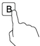
To lock the controls
Touch the Child Lock control button around three seconds. The timer indicator will show "Lo", and Child Lock function be active.
To unlock the controls
- Make sure the electric hob is turned on.
- Touch and hold the Child Lock control button around 3 seconds, the buzzer beeps once and "Lo" disappears in timer indicator, the Child Lock be inactive.
- You can now start using your electric hob.
WARNING:
Under the child lock mode, all controls button be disable except the ON/OFF button ① and child lock button.
You can always turn the hob off with the ON/OFF ① control in an emergency, but you shall unlock the hob first in the next operation.
NOTE:
Under Child Lock function, if turn the hob off without inactive the Child Lock function. When turn on the hob later, the Child Lock function will still valid.
Using the Timer
When the hob is turned on, you can use the timer in two different ways:
- You can use it as a minute minder. In this case, the timer will not turn any cooking zone off when the set time is up.
- You can set it to turn either or more than one cooking zones off.
- You can set the minute minder/timer for up to 99 minutes.
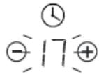
Timer overview

flowchart
graph TD
    A["Clock"] --> B["Minute display shows the number of minutes"]
    C["Timer control"] --> D["- 36 +"]
    D --> E["+"]
Using the Timer as a Minute Minder
If you have not selected any cooking zones
- Touch the timer control button ⏻, the number in timer indicator flashing.
- Then adjust Minute Minder setting follows below:
- Set heat setting by touching the ⏻ or Ⓕ button.
- If press and hold either of the two buttons, the value will adjust down or up rapidly in circle.
Note: When the timer indicator flashing, touch timer control button another time, can quick confirm the timer setting.
- When the minute minder is set, it will begin to count down immediately, the display will show the remaining time.
- Buzzer will beep for 30 seconds and timer indicator shows “- - “when the setting time finished. Any efficient touching of control buttons during it, would end up the buzzer beeps.
- If press and hold either of the two buttons, the value will adjust down or up rapidly in circle.
Setting the timer to turn cooking zone off

natural_image
Simple line drawing of a hand holding a circular object with a dot on the top (no text or symbols)
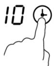
-
Touch the heating zone selection control button 📄 to select the cooking zone you wish to set timer for.
-
Touch the timer control button ⏻, the number in timer indicator flashing.
-
Then adjust Timer setting
- Set heat setting by touching the ⏻ or Ⓕ button.
- If press and hold either of the two buttons, the value will adjust down or up rapidly in circle.
Note: When the timer indicator flashing, touch timer control button another time, can quick confirm the timer setting.
- When the timer is set, it will begin to count down immediately, the display will show the remaining time.
Note: The red dot next to power level indicator will illuminate for those zones be set with timer. You can check timer setting of different cooking zone which set with timer, by active this cooking zone.
Note: If more than one heating zone has timer setting, the timer indicator will show the lowest time. The red dot next to power level indicator will flash.
- When cooking timer expires, the corresponding cooking zone will be switch off automatically.
Note: The default setting of minute reminder and timer is 30 minutes.
Note: After adjusting, the setting in timer indicator will flashing for 5 seconds and then stop flashing, then the setting be confirmed.
Note: The minute reminder and timer can be use at same time, timer indicator shows the lowest time setting. If the lowest setting is minute reminder, the red dot next to timer indicator will flash. If the lowest setting is timer setting, the red dot of corresponding cooking zone power level indicator will flash.
Note: If indicator shows timer setting of cooking zone. To check minute reminder setting, press the timer control button ⏱, the indicator will show minute reminder setting.
Detection of Pan and Small Articles
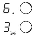
For induction hob, if display flashes " " alternately with heat setting.
- you have not placed a pan on the correct cooking zone or,
- the pan you're using is not suitable for induction cooking or,
- the pan is too small or not properly centered on the cooking zone.
Notes:
- No heating takes place unless there is a suitable pan on the cooking zone.
- The display will auto turn off after 2 minutes if no suitable pan is placed on it.
- When an unsuitable size or non-magnetic pan (e.g. aluminum), or some other small item (e.g. knife, fork, key) has been left on the hob, the corresponding cooking zone will automatically turn off in 1 minute.
Residual Heat Warning

Beware of hot surfaces
When the hob has been operating for some time, there will be some residual heat. The letter “H” appears in power setting indicator to warn you to keep away from it.
It can also be used as an energy saving function:
if you want to heat further pans, use the hotplate that is still hot.
Auto Shutdown
Another safety feature of the hob is auto shutdown. This occurs whenever you forget to switch off a cooking zone. The default shutdown times as below table:
| Power level | 1 | 2 | 3 | 4 | 5 | 6 | 7 | 8 | 9 |
| Default working timer (hour) | 8 | 8 | 8 | 4 | 4 | 4 | 2 | 2 | 2 |
Over-heat Protection
A temperature sensor equipped can monitor the temperature inside the hob. When an excessive temperature is monitored, the hob will auto stop operation.
Over-flow Protection
For your safety, the programmer will auto shut off the power if liquid boiling or wet cloth over touch control panel. All control buttons became invalid except ON/OFF and Child Lock button, unless you wipe the touch control area dry.
Heat Settings
The settings below are guidelines only. The exact setting will depend on several factors, including your cookware and the amount you are cooking. Experiment with the Ceramic hob to find the settings that best suit you.
| Heat setting | Suitability |
| 1 - 2 | • delicate warming for small amounts of food• melting chocolate, butter, and foods that burn quickly• gentle simmering• slow warming |
| 3 - 4 | • reheating• rapid simmering• cooking rice |
| 5 - 6 | • pancakes |
| 7 - 8 | • sautéing• cooking pasta |
| 9 | • stir-frying• searing• bringing soup to the boil• boiling water |
Cleaning and maintenance
WARNING:
Before any maintenance or cleaning work is carried out, DISCONNECT the appliance from ELECTRICITY supply and ensure the appliances is completely cool.
Cleaning the Hob Surface
- Clean spillages from the hob surface as soon as possible after use. Always ensure the surface is cool enough before cleaning.
- Use a soft cloth or kitchen paper to clean the surface. If the spillage has dried on the surface, you may need to use a specialist vitro-ceramic glass cleaner, which is available for most of supermarkets.
- Do not use other abrasive cleaners and/or wire wool ect., as it may scratch the ceramic glass surface of your hob.
Damage from Sugary Spills and Melted Plastic
- Special care should be taken when removing hot substances to avoid permanent damage of the glass surface.
- Sugary spillovers (such as jellies, fudge, candy, syrups) or melted plastics can cause pitting of the surface of your cooktop (not covered by the warranty) unless the spill is removed while still hot. Special care should be taken when removing hot substances.
Maintenance of the Hob
If you find something goes wrong for your hob, before contact the service or where you purchased it, please check whether below:
-
There is no power to the appliance:
-
Check whether there is a power cut of your department;
- Check whether the appliance be connected to electricity properly;
- Has the timer setting elapsed;
- Whether it reaches the longest cooking time setting and auto shut off;
-
Whether there is liquid boiling over touch control panel and overflow protection devices auto shut off;
-
The touch control panel buttons can't be active:
- Whether it's under "Child Lock", which there is "Lo" shows in timer displayer;
- Whether liquid/wet cloth over touch control panel active overflow protection;
- After cooking there is "H" shows on display:
- This is normal. The hob is with Residual Heat Warning safety features. It will remain on until the surface is cool enough for touch.
- After turn off, the fan of induction hob remains working for a while:
-This is normal, this is to help appliances completely cool down.
- Some pans make crackling or clicking noises during use of induction hob:
-This is normal, it's the sound of induction coils during working, and for different construction of your cookware, the clicking might be slightly different.
- The glass is being scratched:
-Check whether you use unsuitable cookware, like rough-edged cookware.
-Check whether unsuitable, abrasive scourer or cleaning products being used.
- The heating element of ceramic hob turns on and off alternately when working:
-This is normal and natural feature for ceramic hob. Programmer of ceramic hob, together with the thermostat or thermocouple in heating element, could control the hob work at set power level and avoid overheat by heating element work on/off alternately.
-If working at highest power level, heating element will continue turn on for a certain time then on/off alternately.
-If working at other lower power level, heating element will on/off alternately at certain frequency since beginning based on power setting of the cooking zone.
Hints and Tips
| What? | How? | Important! |
| Everyday soiling on glass (fingerprints, marks, stains left by food or non-sugary spillovers on the glass) | 1. Switch off the power supply.2. Apply a vitro-ceramic glass cleaner while the glass is still warm (but not hot!)3. Rinse and wipe dry with a clean cloth or paper towel.4. Switch on the power supply to the hob. | ·When turn off the power supply of hob, there will be no 'hot surface' indication but the cooking zone may still be hot! Take extreme care.·Heavy-duty scourers, some nylon scourers and harsh/abrasive cleaning agents may scratch the glass. Always read the label to check if your cleaner or scourer is suitable.·Never leave cleaning residue on the hob glass surface: the glass may become stained. |
| Boil over, melts, and hot sugary spills on the glass | Remove these immediately with a fish slice, palette knife or razor blade scraper suitable for ceramic glass of hob, but beware of hot cooking zone surfaces:1. Switch off the power supply.2. Hold the blade or utensil at a 30° angle and scrape the soiling or spill to a cool area of the hob.3. Clean the soiling or spill up with a dish cloth or paper towel.4. Follow steps 2 to 4 for 'Everyday soiling on glass' above. | ·Remove stains left by melts and sugary food or spillovers as soon as possible. If left to cool on the glass, they may be difficult to remove or even permanently damage the glass surface.·Cut hazard: when the safety cover is retracted, the blade in a scraper is razor-sharp. Use with extreme care and always store safely and out of reach of children. |
| Spillovers on the touch controls. | 1. Switch off the power supply.2. Soak up the spill3. Wipe the touch control area with a clean damp sponge or cloth.4. Wipe the area completely dry with a paper towel.5. Switch on the power supply to the hob. | The hob may beep and turn itself off, and the touch controls may not function while there is liquid on them. Make sure you wipe the touch control area dry before turning the hob back on. |
Failure Inspection for induction hob
Operation of your appliance can lead to errors and malfunctions. The following tables contain possible causes and notes for resolving an error message or malfunction. It is recommended to read the tables carefully below in order to save your time and money that may cost for calling to the service center.
| Problem | Possible causes | What to do |
| E1/E2 | Abnormal supply voltage | Please check whether power supply is normal, Power on after the power supply is normal. |
| E3 | High temperature of the pan sensor | Check whether no liquid in pan, fill with liquid then restart. |
| E5 | High temperature of the IGBT temperature sensor | Please restart after the induction hob cools down. |
For all other error codes, switch off and call your service provider.
Merci !
| A (mm) | B (mm) | C (mm) | D | E |
| 760 mm | 50 mmminimum | 20 mmminimum | Entrée d'air | Sortie d'air5 mm |
natural_image
Diagram showing a rectangular panel with a small inset view of a saw cutting tool and screw base (no text or symbols)
natural_image
Diagram of a layered structure with arrows indicating downward forces or movement, no text or symbols present.
natural_image
Abstract geometric diagram with three shaded rectangles and a diagonal line, no text or symbols present
natural_image
Simple line drawing of a cooking pot with a U-shaped magnet nearby (no text or symbols)
natural_image
Simple line drawing of a cooking pot with crossed-out X marks (no text or symbols)
natural_image
Simple line drawing of a cooking pot with crossed-out X marks (no text or symbols)

natural_image
Simple line drawing of a cooking pot with crossed-out X marks (no text or symbols)
natural_image
Simple line drawing of a cooking pot with crossed-out X marks (no text or symbols)
natural_image
Simple line drawing of a cooking pot with crossed arrows indicating pressure or resistance (no text or symbols)
natural_image
Simple line drawing of a hand pointing upward with a circular symbol (no text or labels)
natural_image
Line drawing of a cooking pot on a stand (no text or symbols)
natural_image
Simple line drawing of a hand holding a circular object with a dot at the top (no text or symbols)
natural_image
Simple line drawing of a hand pointing upward with a circular symbol on the index finger (no text or labels)
natural_image
Simple line drawing of a hand holding a circular object with a dot at the top (no text or symbols)
natural_image
Simple line drawing of a hand pressing a button with an '+' symbol (no text or labels)
natural_image
Simple line drawing of a hand holding a circular object with a dot at the top (no text or symbols)
| A (mm) | B (mm) | C (mm) | D (mm) | E |
| 760 mm | 50 mm minstens | 20 mm minstens | Luchttoevoer | Luchtafvoer 5 mm |
natural_image
Diagram showing a rectangular panel with a small inset view of a mechanical component (no text or symbols)
natural_image
Diagram of a layered structure with arrows indicating force or movement, no text or symbols present
natural_image
Pure geometric diagram showing two overlapping rectangles with diagonal hatching, no text or symbols present
natural_image
Simple line drawing of a cooking pot with a U-shaped magnet nearby (no text or symbols)
natural_image
Simple line drawing of a cooking pot with crossed-out X marks (no text or symbols)

natural_image
Simple line drawing of a cooking pot with crossed-out X marks (no text or symbols)
natural_image
Simple line drawing of a cooking pot with crossed-out X marks (no text or symbols)
natural_image
Simple line drawing of a cooking pot with crossed-out X marks (no text or symbols)

natural_image
Simple line drawing of a cooking pot with crossed arrows indicating pressure or resistance (no text or symbols)

natural_image
Simple line drawing of a hand pointing upward with a circular symbol (no text or labels)
natural_image
Line drawing of a cooking pot on a stand (no text or symbols)
natural_image
Simple line drawing of a hand holding a circular object with a dot at the top (no text or symbols)
natural_image
Simple line drawing of a hand pointing upward with a circular symbol on the index finger (no text or labels)
natural_image
Simple line drawing of a hand holding a circular object with a dot at the top (no text or symbols)
natural_image
Simple line drawing of a hand holding a circular object with a dot at the top (no text or symbols)
| Modelo | L | A. | H | D | A | B | X |
| Placa de inducción 60 cm | 590 | 520 | 56 | 48 | 555+5-0 | 495+5-0 | 50 min |
A (mm)
760mm
B (mm)
50 mm mínimo
C (mm)
20mm mínimo
D
Entrada de aire
E
natural_image
Diagram showing a rectangular panel with a small inset view of a mechanical component (no text or symbols)
natural_image
Diagram of a layered structure with arrows indicating force or movement, no text or symbols present
natural_image
Abstract geometric diagram with three shaded rectangles and a diagonal line, no text or symbols present
natural_image
Simple line drawing of a cooking pot with a U-shaped magnet (no text or symbols)
natural_image
Simple line drawing of a cooking pot with crossed-out X marks (no text or symbols)

natural_image
Simple line drawing of a cooking pot with crossed-out X marks (no text or symbols)

natural_image
Simple line drawing of a cooking pot with crossed-out X marks (no text or symbols)

natural_image
Simple line drawing of a cooking pot with crossed-out X marks (no text or symbols)

natural_image
Simple line drawing of a cooking pot with crossed arrows indicating pressure or resistance (no text or symbols)
natural_image
Simple line drawing of a hand pointing upward with a circular symbol (no text or labels)
natural_image
Line drawing of a cooking pot on a stand (no text or symbols)
natural_image
Simple line drawing of a hand holding a circular object with a dot at the top (no text or symbols)
natural_image
Simple line drawing of a hand pointing upward with a circular symbol on the index finger (no text or labels)
natural_image
Simple line drawing of a hand holding a circular object with a dot at the top (no text or symbols)
natural_image
Simple line drawing of a hand pressing a button with an '+' symbol (no text or labels)
natural_image
Simple line drawing of a hand holding a circular object with a dot at the top (no text or symbols)