USER MANUAL IH 4 HTB 2FZ 929C VALBERG
Induction hob (suction)
Plaque à induction (aspiration)
natural_image
Technical line drawing of a mechanical assembly with a ladder-like component and housing (no text or symbols)
natural_image
Technical line drawing of a ladder-like structure with a labeled point C (no text or symbols beyond label)
natural_image
Technical line drawing of a rectangular mechanical part with a labeled point D (no text or symbols on the object itself)
natural_image
Simple line drawing of a cylindrical object with a labeled point E (no text or symbols on the object itself)
natural_image
Simple line drawing of a ring with a labeled point G at the bottom (no text or symbols beyond the label)
natural_image
Simple line drawing of a rectangular object with a vertical line and a labeled circle (no text or symbols)

Thank you!
Thank you for choosing this VALBERG product.
VALBERG products are chosen, tested, and recommended by ELECTRO DEPOT, so you can be sure you are getting a top-quality, easy-to-use product that won't let you down.
We're confident your new device will be a pleasure to use every day!
Welcome to ELECTRO DEPOT.
Table of Contents

Product overview
Parts

Product usage
Dimensions
Installation
Wall drilling and bracket fixing
Electrical schematic diagram
Operation instructions

Cleaning and maintenance
Cleaning and maintenance
Troubleshooting
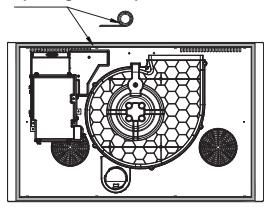
Product description
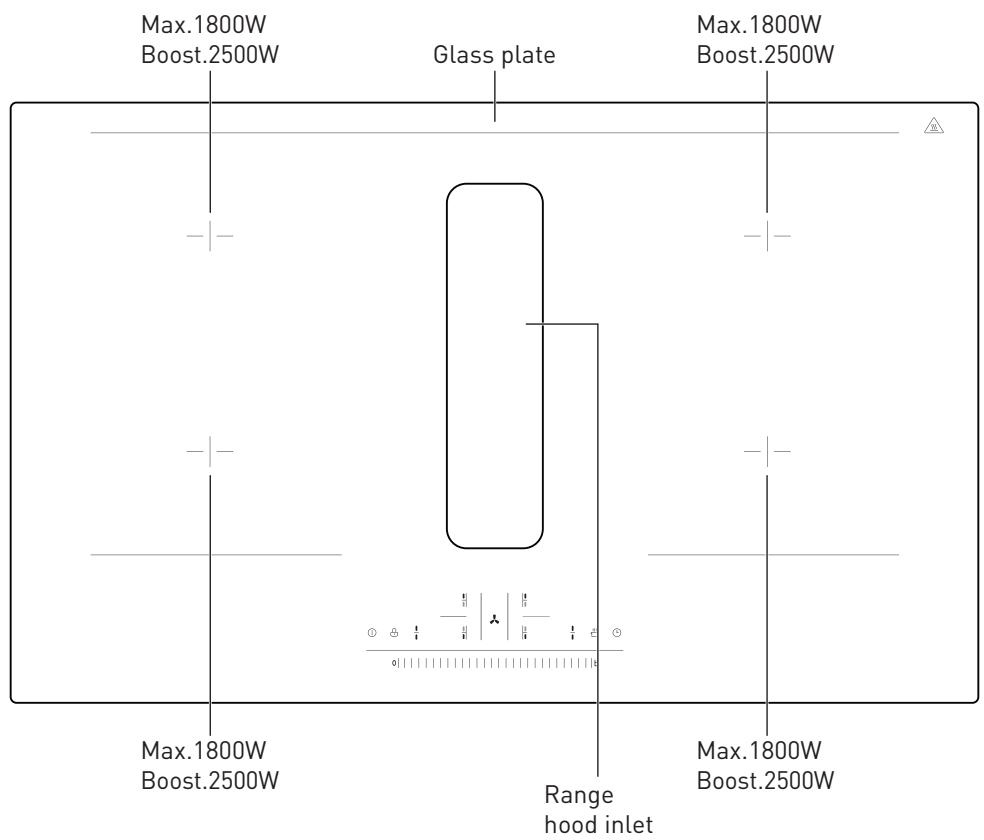
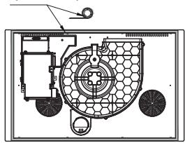
Parts
A The main body
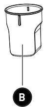
B Cup
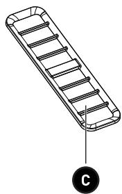
C Grille
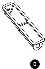
D Filter
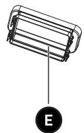
E Direct conversion
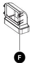
F 90°conversion head
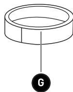
G Rubber ring
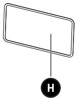
H Sponge strip
I Screw M4*10 x 4
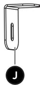
J Mounting bracket x 4
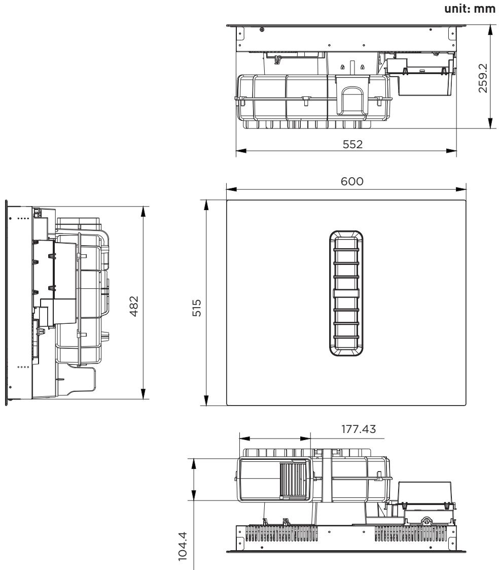
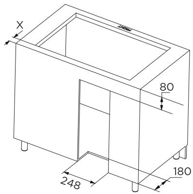
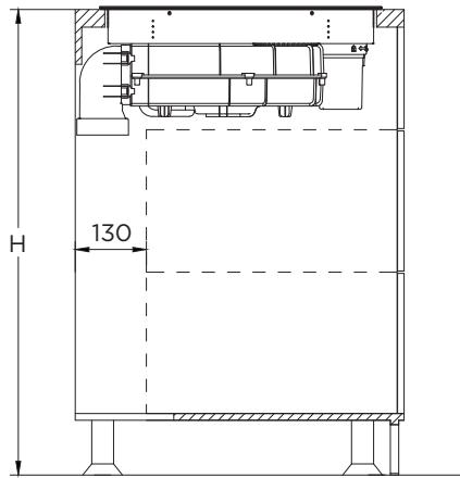
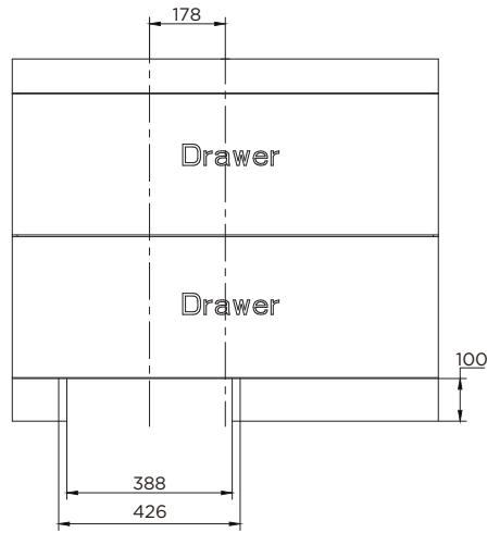
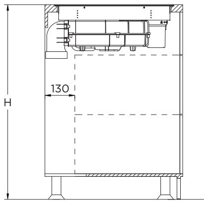
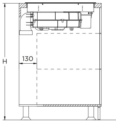
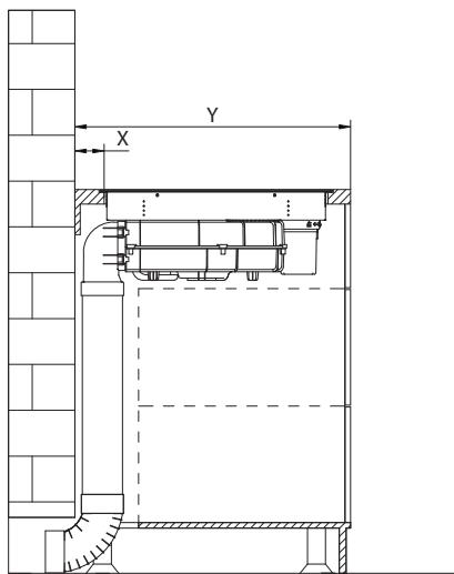
Dimensions
Installation
Before installing the hob, make sure that
- The work surface is square and level, and no structural members interfere with space requirements.
• The work surface is made of a heat-resistant and insulated material.
• If the hob is installed above an oven, the oven has a built-in cooling fan.
- The installation will comply with all clearance requirements and applicable standards and regulations.
- A suitable isolating switch providing full disconnection from the mains power supply is incorporated in the permanent wiring, mounted and positioned to comply with the local wiring rules and regulations.
- The isolating switch must be of an approved type and provide a 3 mm air gap contact separation in all poles (or in all active [phase] conductors if the local wiring rules allow for this variation of the requirements).
- The isolating switch will be easily accessible to the customer with the hob installed.
- You consult local building authorities and by-laws if in doubt regarding installation.
- You use heat-resistant and easy-to-clean finishes (such as ceramic tiles) for the wall surfaces surrounding the hob.
After installing the hob, make sure that
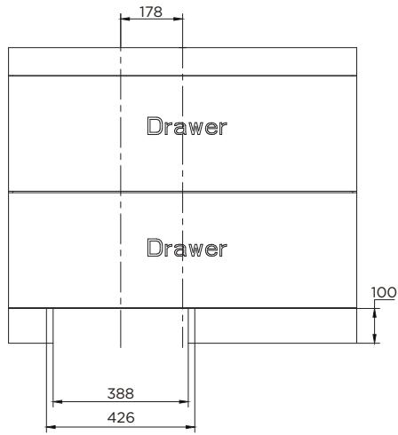
- The power supply cable is not accessible through cupboard doors or drawers.
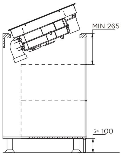
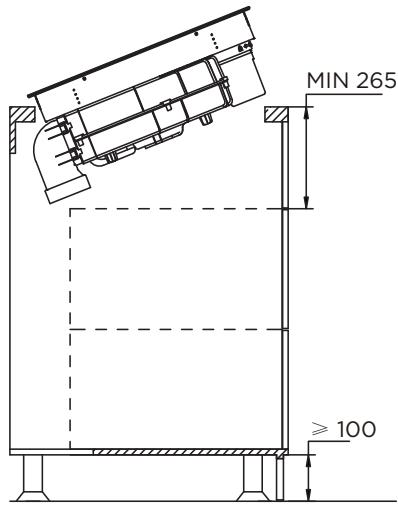
- There is adequate flow of fresh air from outside the cabinetry to the base of the hob. If the hob is installed above a drawer or cupboard space, a thermal protection barrier is installed below the base of the hob.
• The isolating switch is easily accessible by the customer.
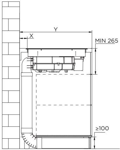
- Please locate at the lower part of the stove and set a ventilation hole with a total area of no less than 100 cm^2 to maintain the circulation with the outside air, otherwise it will cause the accumulation of leaking gas and cause explosion. If liquefied petroleum gas cylinder is used, the distance between the stove and the gas cylinder should be greater than 100 cm.

CAUTION!
- The induction hotplate must be installed by qualified personnel or technicians. We have professionals at your service. Please never conduct the operation by yourself.
- The hob will not be installed directly above a dishwasher, fridge, freezer, washing machine or clothes dryer, as the humidity may damage the hob electronics.
- The induction hotplate shall be installed such that better heat radiation can be ensured to enhance its reliability.
• The wall and induced heating zone above the table surface shall withstand heat.
• To avoid any damage, the sandwich layer and adhesive must be resistant to heat.
• A steam cleaner is not to be used.
Connecting the hob to the mains power supply

CAUTION!
Check with an electrician whether the domestic wiring system is suitable without alterations. Any alterations must only be made by a qualified electrician.
This hob must be connected to the mains power supply only by a suitably qualified person. Before connecting the hob to the mains power supply, check that:
• The domestic wiring system is suitable for the power drawn by the hob.
• The voltage corresponds to the value given in the rating plate.
- The power supply cable sections can withstand the load specified on the rating plate.
To connect the hob to the mains power supply, do not use adapters, reducers, or branching devices, as they can cause overheating and fire.
The power supply cable must not touch any hot parts and must be positioned so that its temperature will not exceed 75^ C at any point.
Wall drilling and bracket fixing
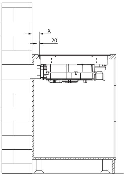
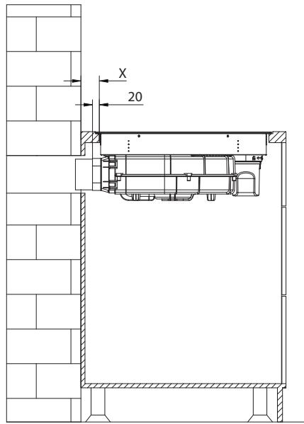
INSTALLATION FLUSH TOP
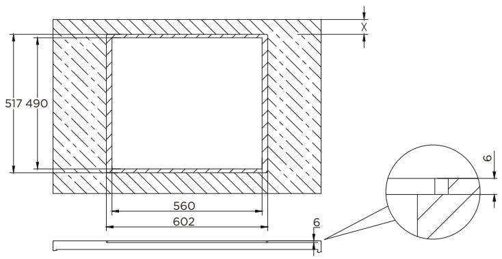
| Table width (Y) | X |
| 600 - 650mm | 54mm |
| ≥slant 650mm | 65mm |

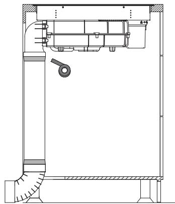
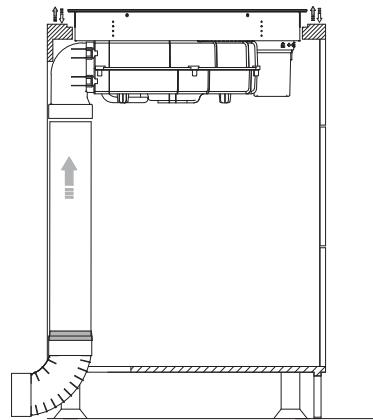
Internal circulation
1. Stick sponge strips
Sponge strip
natural_image
Technical diagram of a mechanical or electrical component with no visible text, numbers, or symbols.
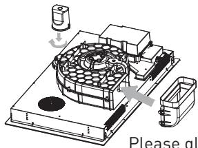
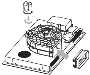
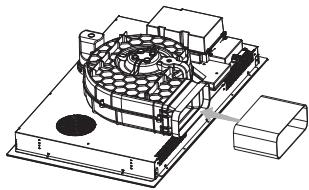
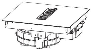
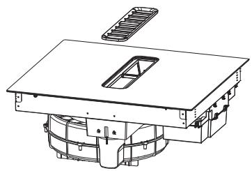
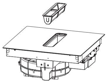
2. Install the water cup and adapter
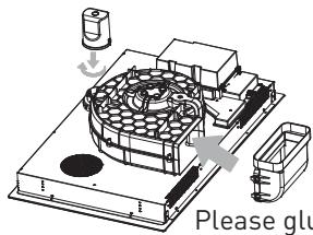
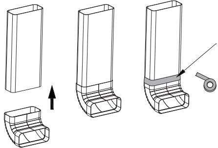
Please glue and fix after installation
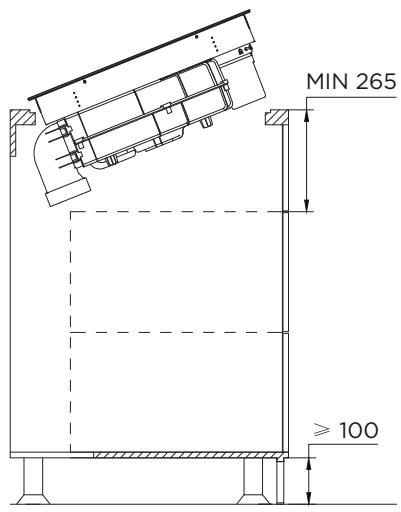
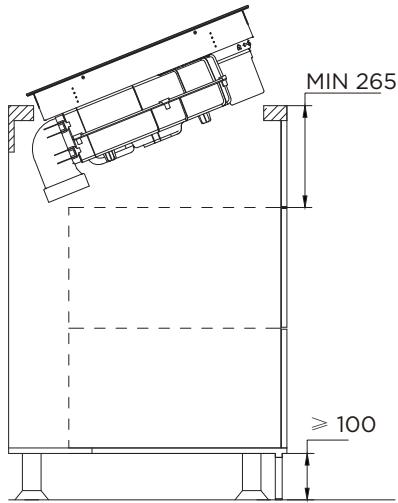
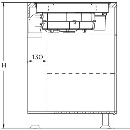
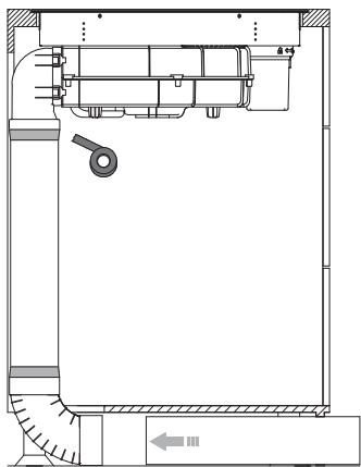
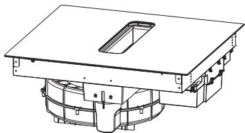
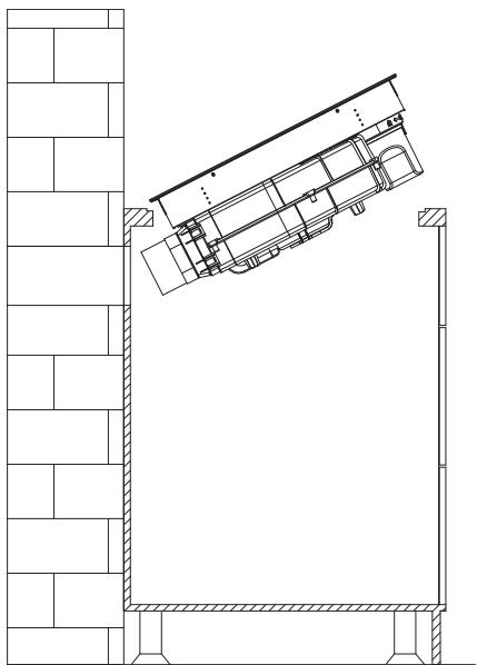
Put the whole machine in the cabinet and adjust the product
Put the whole machine in the cabinet and adjust the product
natural_image
Technical line drawing of three mechanical components with an arrow indicating assembly or adjustment (no text or symbols present)

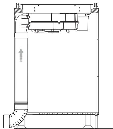
natural_image
Technical schematic of a mechanical or fluidic device with internal components and flow indicators (no text or symbols)

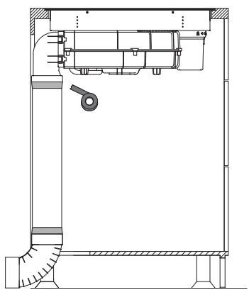
natural_image
Technical line drawing of a mechanical assembly with no visible text or symbols

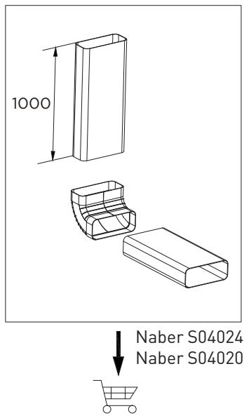
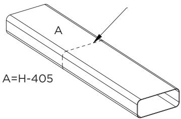
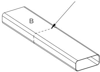
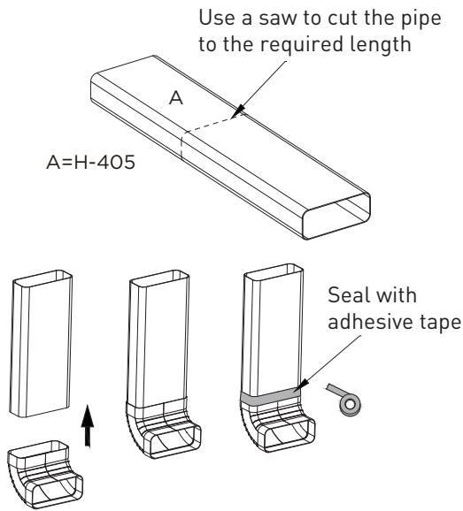
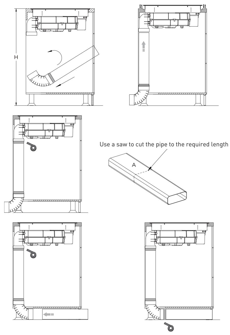
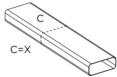
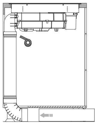
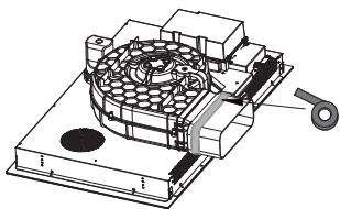
Use a saw to cut the pipe to the required length
natural_image
Isometric line drawing of a rectangular prism with labeled point B (no text or symbols beyond label)
natural_image
Technical line drawing of a mechanical assembly with no visible text or symbols

natural_image
Technical line drawing of a mechanical assembly with no visible text or symbols
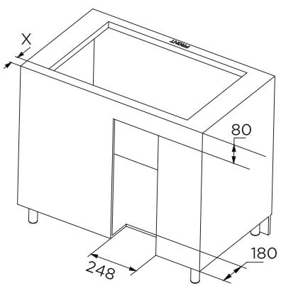
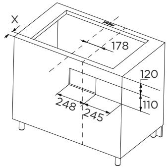
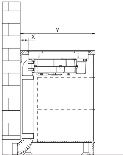
Cabinet opening size
INSTALLATION FLUSH TOP
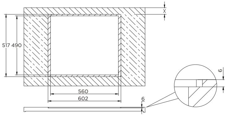
| Table width (Y) | X |
| 600 - 650mm | 54mm |
| ≥slant 650mm | 65mm |

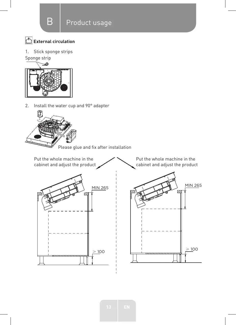
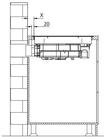
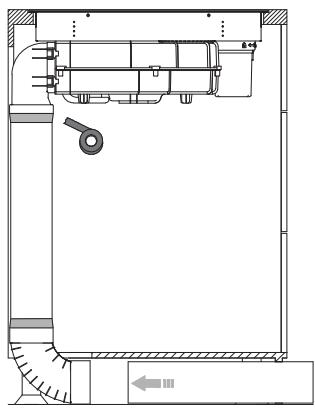
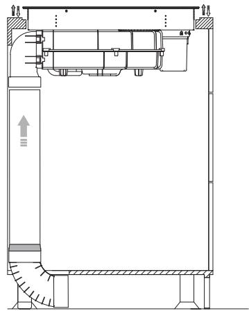
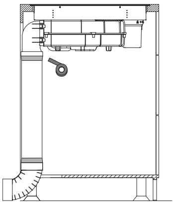
External circulation
1. Stick sponge strips
Sponge strip

natural_image
Technical diagram of a mechanical or architectural component with no visible text, numbers, or symbols.
2. Install the water cup and 90^ adapter
natural_image
Technical diagram of a mechanical device with fan and housing, no visible text or symbols
Please glue and fix after installation
Put the whole machine in the cabinet and adjust the product
Put the whole machine in the cabinet and adjust the product
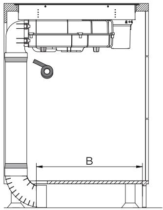
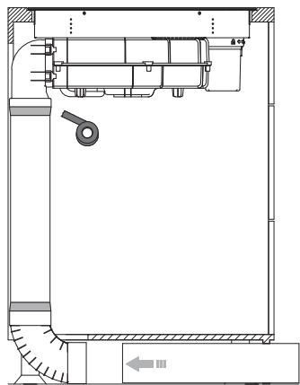
B
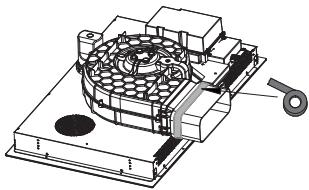
Product usage
Scheme I: Installation of water cup and straight adapter
natural_image
Mechanical assembly diagram showing a fan-like component with internal components and directional arrows (no text or labels)
Please glue and fix after installation.
| Table width (Y) | X |
| 600 - 650mm | 54mm |
| ≥slant 650mm | 65mm |
natural_image
Technical line drawing of a mechanical assembly with fan-like components and housing (no text or symbols)

natural_image
Technical line drawing of a mechanical device with internal components and mounting base (no text or symbols)

natural_image
Architectural line drawing of a building facade with structural elements and a suspended platform (no text or symbols)

Internal circulation

External circulation

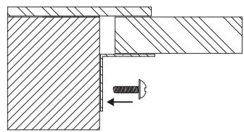
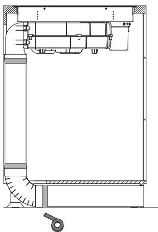
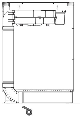
After the product is installed, install four supports on both sides of the product to prevent the product from falling of.
natural_image
Technical drawing of a mechanical joint or bracket assembly with hatched areas and a central fastener (no text or symbols)
Electrical schematic diagram
| Electrical connection | Connection diagram home side | Power Cord |
| 220-240V~ | 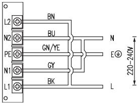 | 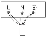 | 5G 2.5mm ^2 H07RN-FL1: BKL2: BNN1: GYN2: BUPE: GN/YE |
| 380-415V~ | 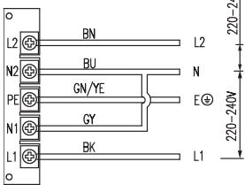 |  | 5G 2.5mm ^2 H07RN-FL1: BKL2: BNN1: GYN2: BUPE: GN/YE |
L1, L2= Phase, N1, N2= Neutral, PE= Earth
Diameter of the connecting electric wire must exceed 4.0mm^2
Operation instructions
Speed adjustment. (For some models)
| 1 | The main switch | [25ZD] | Child lock |
| 1/1 | Bridging |  | Cooking zone to choose |
| The fan selection | [750H] | Heat preservation |
| L | Time | d|||||||||||b | Gear control area |
| • | Activation status light | 8 | Fan or cooking zone gear display light |
| (●) | Fan linkage activation display | 88 | Time display |
| Button | Function | Remarks |
| ●1 | The main switch | • Short press the main switch to turn the maching on or off. |
| ● | Child lock | • Long press the child lock button to enter the lock mode, the child lock indicator light on, except the main switch and the child lock button, other keys are invalid.• Long press the button to unlock. The child lock indicator light goes of and other keys are restored. |
| ●1 | Bridging | • Short press the bridge button on the left, the indicator light is in the active state, the left cooking zones are started.• The two cooking zones on the left can be adjusted simultaneously in bridging mode. In the working state, short press will cancel the bridging operation and close the left cooking zones. In the bridging state, the left cooking zones can be operated regularly at the same time.• Short press the bridge button on the right, the indicator light is in the active state, the cooking zones on the right are started. The two cooking zones on the right can be adjusted simultaneously in bridging mode. In the working state, short press will cancel the bridging operation and close the right cooking zones. In the bridging state, the right cooking zones can be operated regularly at the same time. |
| [SAHZ] | Heat preservation | Press the heat preservation button to enter the heat preservation state. The current working cooking zone is running in the lowest gear, and the screen shows L; When the heat preservation button or other buttons are pressed again, the heat preservation state is cancelled, and the cooking zone will return to the previous working state.Under the condition of heat preservation, the indicator light is on. |
 | Time | The cooking zone timing time can be set to 00 - 99min; In the selected state of the cooking zone, press the timing key to timing the selected cooking zone;The timing time can be set in the units and tens of minutes, first set the tens digit, and then set the units digit. During the setting of tens digit, the finger leaves the slider for three seconds, or press the timing button again to enter the units digit setting;During the setting of units digit, the finger leaves the slider for three seconds and enters the timer countdown state; During the setting, press the timing button again to cancel the timing setting. Set the time by sliding the slider bar;During the timing operation, the timing time decreases by minute. After the timing is over, the buzzer 6 sounds will be extin-guished. |
| [280] | Upper left furnace selection key | The upper left furnace is selected for power or timing setting, and the digital screen will display the selected cooking zone's power level, and the initial setting of 5 levels of power is performed. When the cooking zone is selected, the digital tube flashes for 3 seconds, and the sliding button can adjust the gear. |
| [282] | Lower left furnace selection keyRight upper furnace selection key | Select the lower left furnace for power or timing setting, the left indicator blinking indicates that the current digital tube displays the state of the cooking zone, the initial setting of 5 levels of power, select the cooking zone, the digital tube flashing for 3 seconds, sliding button can adjust the gear.The upper right furnace is selected for power or timing setting, and the blinking indicator on the right indicates that the current digital tube displays the state of the cooking zone, and the initial setting of the power of 5 levels is performed. When the cooking zone is selected, the digital tube flashes for 3 seconds, and the sliding button can adjust the gear. |
| Lower right furnace selection key | The upper fight furnace is selected for power or timing setting, and the blinking indicator on the right indicates that the current digital tube displays the state of the cooking zone, and the initial setting of the power of 5 levels is performed. When the cooking zone is select- ed, the digital tube flashes for 3 seconds, and the sliding button can adjust the gear. |
| Fan selection button | When the fan is powered on for the first time, the linkage button is on and the fan is in linkage state.Select the fan button, the sliding bar can directly control the size of the fan (1-8 b gear), the highest can be b gear, after 5min, jump to 7 gear, if you select 8 gear, after 8 minutes, jump to 7 gear.The screen on the fan button shows the fan gear.When selecting the fan, press the fan button again to enter the 1-minute delay shutdown state, and it will be displayed in the digital tube. If you press it again, the fan will be shut down directly. |
| Single 8 digital tube | Display 1-8 gears of current burner fire;"b" means hob boost level and fan boost level;"u" means no pot;"H" furnace surface residual temperature is too high reminder;Display 0 to stop the power output of the cooking zone;Under the fault state, the wind speed gear of the current faulty cooking zone or smoker is displayed as "E"; |
| Double 8 digital tube | Timing display, 00 - 99min;Under the fault state, the current fault code is displayed;Display "☐" is standby mode. |
| Slider gear control function | The stove head gear, wind speed gear, timing time can be set by sliding the sliding bar left and right.When shutting down a stove head or fan, it will scan furnace 1, furnace 2, furnace 3, furnace 4, fan in turn, and transfer the control to the working stove head or fan. |
| (●) | Linkage activation display | The linkage button is activated when the product is powered on for the first time, and the previous state is remembered each time the product is powered on.Long press 3S to cancel the linkage between the fan and the hob.Long press the fan selection button to enter the linkage of the fan and the hob:(1) Obtain the maximum power value of the current stove to synchronize the fan power with the maximum power of the current stove. If the maximum power of the four furnaces is set to 8 by default, the fan will also be set to 8.(2) Linkage of the fan and the hob has adaptive function.- For example, when the cooking zone is working at the 5th gear, and the fan gear is manually adjusted to the 6th gear, 6-5 = 1; Then when the furnace gear is manually adjusted to N gear again, the fan gear is N+1; Of course, when the fan gear reaches 9 gear, the fan gear will not increase.- For example, when the cooking zone is working at the 5th gear, and the fan gear is manually adjusted to the 4th gear, 4-5 = -1; Then when the furnace gear is manually adjusted to N gear again, the fan gear is n-1; Of course, when the fan gear reaches 1 gear, the fan gear will no longer be reduced. |
B Product usage
- Power coordination (ensure that the output power will not exceed 3600W when the two cooking zones on the same side work simultaneously).
In the current working adjustment process of induction furnace, the maximum power of the two cooking zones on the same side should not exceed 3600W. If the calculated total power exceeds 3600W during the adjustment process, reduce the unoperated cooking zone power on the same side to ensure that the current power is the target power desired by the user and the total power does not exceed 3600W.
- Power adjustment function: Press two linkage keys to enter the power adjustment state. After entering the power adjustment state, press the left bridge key to reduce the maximum power and press the right bridge key to increase the maximum power. There are 5 power levels, 2800W, 3600W, 4600W, 5800W, 7200W. If you do not adjust the maximum power for 30 seconds or press the power button, the system enters the shutdown state.
- There are two mode in the product, energy-saving mode (external mode) and conventional mode (internal cycle mode). There is no boost power in the energy-saving mode, and there is two boost power in the conventional mode, which is the convention- al mode by default; In standby mode, press and hold the fan key and child lock key 2S to enter the mode switching state. At this time, press the fan key to switch modes. 0 indicates the normal mode and 1 indicates the energy saving mode.
Furnace power distribution (Note: Intermittent: 1000W for intermittent)
| Speed | 0 | 1 | 2 | 3 | 4 | 5 | 6 | 7 | 8 | b |
| Power (W) | 0 | 100 | 200 | 300 | 800 | 1200 | 1400 | 1600 | 1800 | 2500 |
Power distribution when using the flexible zone
| Speed | 0 | 1 | 2 | 3 | 4 | 5 | 6 | 7 | 8 | b |
| Power (W) | 0 | 100 | 200 | 300 | 800 | 1000 | 1200 | 1400 | 1600 | 1800 |
Fan power speed distribution
| Speed | 0 | 1 | 2 | 3 | 4 | 5 | 6 | 7 | 8 | b |
| Air volume (m^3/h) | 0 | 290 | 310 | 340 | 360 | 380 | 420 | 470 | 540 | 580 |
| Time of operation(min) | | | | Long run | | | | 8 | 5 |
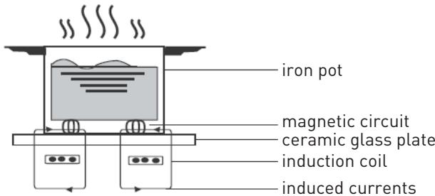
Working theory
- Induction cooking is a safe, advanced, efficient, and economical cooking technology. It works by electromagnetic vibrations generating heat directly in the pan, rather than indirectly through heating the glass surface. The glass becomes hot only because the pan eventually warms it up.
Operation of product
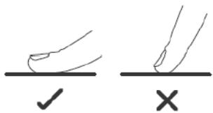
Touch Controls
- The controls respond to touch, so you don't need to apply any pressure.
• Use the ball of your finger, not its tip.
• You will hear a beep each time a touch is registered.
- Make sure the controls are always clean, dry, and that there is no object (e.g. a utensil or a cloth) covering them. Even a thin film of water may make the controls difficult to operate.
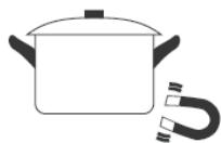
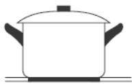
Hoosing the right Cookware

• Only use cookware with a base suitable for induction cooking.
- Look for the induction symbol on the packaging or on the bottom of the pan.
• Dishes will be detected by the device if they measure 14 cm in diameter or more.
- You can check whether your cookware is suitable by carrying out a magnet test. Move a magnet towards the base of the pan. If it is attracted, the pan is suitable for induction.
natural_image
Simple line drawing of a cooking pot with a U-shaped magnet attached (no text or symbols)
• If you do not have a magnet:
1. Put some water in the pan you want to check.
2. If ' does not flash in the display and the water is heating, the pan is suitable.
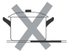
- Cookware made from the following materials is not suitable: pure stainless steel, aluminium or copper without a magnetic base, glass, wood, porcelain, ceramic, and earthenware.
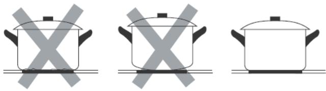
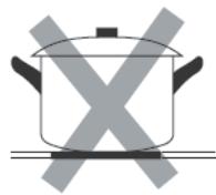
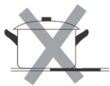
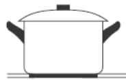
Do not use cookware with jagged edges or a curved base

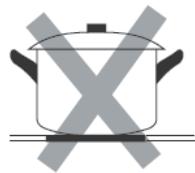
Do not use pressure cookers for heat.
natural_image
Three identical cooking pots with crossed-out X symbols, no text or labels present
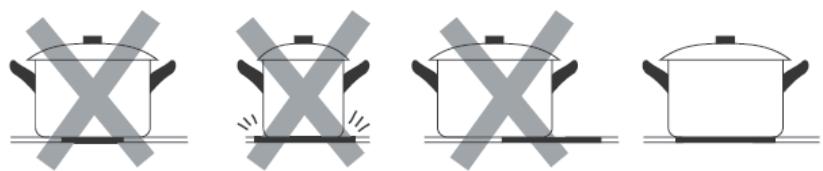
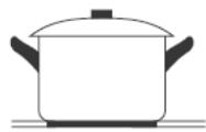
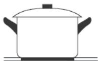
Make sure that the base of your pan is smooth, sits flat against the glass, and is the same size as the cooking zone. Use pans whose diameter is as large as the graphic of the zone selected. Using a pot a slightly wider energy will be used at its maximum efciency. If you use smaller pot efciency could be less than expected. Pot less than 140 mm could be undetected by the hob. Always centre your pan on the cooking zone.
natural_image
Four identical cooking pots with crossed-out X marks, shown in different orientations (no text or symbols)
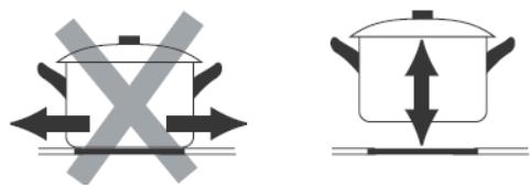
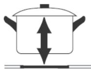
Always lift pans of the Induction hob – do not slide, or they may scratch the glass.
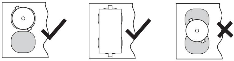
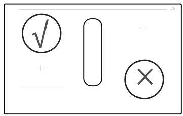
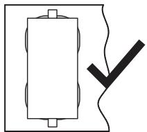
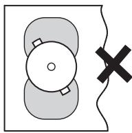
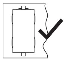
When using the product, please refer to the following illustration for placing the pot. Do not place the pot in the middle.
natural_image
Three abstract diagrams showing circular shapes with checkmarks and X marks, no text or symbols present
Cooking pot must be placed in the glass screen printing area.
Cooking Guidelines

Take care when frying as the oil and fat heat up very quickly, particularly if you're using PowerBoost. At extremely high temperatures oil and fat will ignite spontaneously and this presents a serious fire risk.
Cooking tips
- When food comes to the boil, reduce the temperature setting.
• Using a lid will reduce cooking times and save energy by retaining the heat.
- Minimize the amount of liquid or fat to reduce cooking times.
- Start cooking on a high setting and reduce the setting when the food has heated through.
Simmering, cooking rice
- Simmering occurs below boiling point, at around 85^ C, when bubbles are just rising occasionally to the surface of the cooking liquid. It is the key to delicious soups and tender stews because the flavours develop without overcooking the food. You should also cook egg-based and flour thickened sauces below boiling point.
- Some tasks, including cooking rice by the absorption method, may require a setting higher than the lowest setting to ensure the food is cooked properly in the time recommended.
Searing steak
To cook juicy flavorsome steaks:
- Stand the meat at room temperature for about 20 minutes before cooking.
• Heat up a heavy-based frying pan.
- Brush both sides of the steak with oil. Drizzle a small amount of oil into the hot pan and then lower the meat onto the hot pan.
- Turn the steak only once during cooking. The exact cooking time will depend on the thickness of the steak and how cooked you want it. Times may vary from about 2 – 8 minutes per side. Press the steak to gauge how cooked it is – the firmer it feels the more “well done” it will be.
- Leave the steak to rest on a warm plate for a few minutes to allow it to relax and become tender before serving.
For stir-frying
- Choose an induction compatible flat-based wok or a large frying pan.
- Have all the ingredients and equipment ready. Stir-frying should be quick. If cooking large quantities, cook the food in several smaller batches.
• Preheat the pan briefly and add two tablespoons of oil.
• Cook any meat first, put it aside and keep warm.
- Stir-fry the vegetables. When they are hot but still crisp, turn the cooking zone to a lower setting, return the meat to the pan and add your sauce.
• Stir the ingredients gently to make sure they are heated through.
- Serve immediately.
Detection of Small Articles
- When an unsuitable size or non-magnetic pan (e.g. aluminium), or some other small item (e.g. knife, fork, key) has been left on the hob, the hob automatically go on to standby in 1 minute. The fan will keep cooling down the induction hob for a further 1 minute.
Heat Settings
- The settings below are guidelines only. The exact setting will depend on several factors, including your cookware and the amount you are cooking. Experiment with the induction hob to find the settings that best suit you.
| Heat setting | Suitability |
| 1 - 2 | • delicate warming for small amounts of food• melting chocolate, butter, and foods that burn quickly• gentle simmering• slow warming |
| 3 - 4 | • reheating• rapid simmering• cooking rice |
| 5 - 6 | • pancakes |
| 7 - 8 | • sautéing• cooking pasta |
| b | • stir-frying• searing• bringing soup to the boil• boiling water |
Cleaning and maintenance
Glass surface cleaning, daily maintenance cleaning
- When using cloth to clean, try not to put clean water into the grate.
natural_image
Technical line drawing of a mechanical assembly with a flat plate and cylindrical housing (no text or symbols)
⚠ Clean your water cup regularly.
Clean the grille and perform routine maintenance
• Take the grate, clean it carefully, and then put it back.
natural_image
Technical line drawing of a mechanical assembly with no visible text or symbols
Filter screen cleaning, daily maintenance cleaning
- Take out the filter bracket horizontally, remove the filter from the bracket, and wash it in the dishwasher, or manually clean the filter. The residual water of the filter bracket is taken out horizontally and dumped into the water channel.
natural_image
Technical line drawing of a mechanical assembly with a central component and a small inset view (no text or symbols)
Water cup cleaning, daily maintenance cleaning
- Rotate out the water cup, dump the waste water inside, and install it back.
natural_image
Technical line drawing of a mechanical assembly with a flat plate and cylindrical housing (no text or symbols)
Troubleshooting
| Problem | Possible reason | Solution |
| The induction hob cannot be turned on | No power. | Make sure the induction hob is connected to the power supply and that it is switched on.Check whether there is a power outage in your home or area. If you’ve checked everything and the problem persists, call a qualified technician. |
| The touch controls are unresponsive | The controls are locked. | Unlock the controls. See section “Using your induction cooktop” for instructions. |
| The touch controls are difficult to operate | There may be a slight film of water over the controls or you may be using the tip of your finger when touching the controls. | Make sure the touch control area is dry and use the ball of your finger when touching the controls. |
| The glass is being scratched | Rough-edged cookware.Unsuitable, abrasive scourer or cleaning products being used. | Use cookware with flat and smooth bases. See “Choosing the right cookware”.See “Care and cleaning”. |
| The induction hob or a cooking zone has turned itself of unexpectedly, a tone sounds and an error code is displayed (typically alternating with one or two digits in the cooking timer display). | Technical fault. | Please note down the error letters and numbers, switch the power to the induction hob of at the wall, and contact a qualified technician. |
| The induction hob makes a low humming noise when used on a high heat setting | This is caused by the technology of induction cooking. | This is normal, but the noise should quieten down or disappear completely when you decrease the heat setting. |
| Pans do not become hot and "U" appears in the display. | The induction hob cannot detect the pan because it is not suitable for induction cooking.The induction hob cannot detect the pan because it is too small for the cooking zone or not properly centred on it. | Use cookware suitable for induction cooking. See section "Choosing the right cookware".Centre the pan and make sure that its base matches the size of the cooking zone. |
| Fan noise coming from the induction hob. | A cooling fan built into your induction hob has come on to prevent the electronics from overheating. It may continue to run even after you've turned the induction hob of. | This is normal and needs no action. Do not switch the power to the induction hob of at the wall while the fan is running. |
| Some pans make crackling or clicking noises | This may be caused by the construction of your cookware (layers of different metals vibrating differently). | This is normal for cookware and does not indicate a fault. |
| Light on, but motor does not work | The blades are blocked.The capacitor is damaged.The motor is damaged.The internal wiring of motor is cut of/disconnected. An unpleasant smell may be produced. | Check the bladesReplace capacitor.Replace motor.Replace motor. |
| Both light and motor do notwork | Apart from the above mentioned, check the following: |
| Light damaged.Power cord loose. | Replace lights.Connect the wires as the electric diagram. |
| Oil leakage | Outlet and the air ventilation entrance are not tightly sealed. | Take down the outlet and seal with glue. |
| Vibration | The blade, if damaged, can cause vibrating.The motor is not tightly fastened.The cooker hood is not tightly fixed. | Replace the blade.Fasten the motor tightly.Fixed the cooker hood tightly. |
| Insuficient suction | The distance between the cooker hood and the cooker top is too large.Too much ventilation from open doors or windows. | Readjust the distance.Choose a new place to install the appliance or close some doors / windows. |
| The machine inclines | The fixing screws are not tight enough.The hanging screws are not tightenough | Tighten the fixing screw and make it horizontal.Tighten the hanging screw and make it horizontal. |
Self diagnosis function
| The error code | Reason | Solution |
| 01 | · Furnace surface NTC open circuit | · Replace the furnace surface NTC |
| 02 | · NTC short circuit on furnace surface | · Replace the furnace surface NTC |
| 03 | · The NTC temperature of the furnace surface is too high | · After the shutdown error is reported, wait for the cooling to resume normal operation |
| 04 | · The heat sink NTC is open | · Replace the heat sink NTC |
| 05 | · The radiator NTC is short-circuited | · Replace the heat sink NTC |
| 06 | · Heat dissipation The NTC temperature is too high | · After the shutdown error is reported, wait for the cooling to resume normal operation |
| 07 | · The input low voltage | · Check whether the external input voltage is lower than 150V |
| 08 | · The input high voltage | · Check whether the external input voltage is higher than 270V |
| 09 | · Reception communication failure | · Check whether the connection between the display board and the induction cooker board is faulty, and replace the communication cable |
| 10 | · Furnace surface NTC failure | · Check whether the temperature sensor of the furnace surface is in contact with the furnace surface, and whether there is glass glue contact |
| 11 | · Internal fault, open disk, no synchronization signal | · Check whether the solenoid coil is open, and determine whether to replace the cable disk |
| 12 | · Fan fault | · Check whether the fan module is open |
| 13 | · Dry | · Shut down and run again |
| Failure | Problem | Solution A | Solution B |
| The LED does not come on when unit is plugged in | No power supplied.The accessorial power board and the display board connected failure.The accessorial power board is damaged.The display board is damaged. | The LED does not come on when unit is plugged in.Check the connection.Replace the accessorial power board.Replace the display board. | |
| Some buttons can’t work, or the LED display is not normal | The display board is damaged. | Replace the display board. | |
| The Cooking Mode Indicator comes on, but heating does not start | High temperature of the hob.There is something wrong with the fan.The power board is damaged. | Ambient temperature may be too high. Air Intake or Air Vent may be blocked.Check whether the fan runs smoothly; if not, replace the fan.Replace the power board. | |
| Heating stops suddenly during operation and the display flashes “u” | Pan Type is wrong.Pot diameter is too small. | Use the proper pot (refer to the instruction manual.) | Pan detection circuit is damaged, replace the power board. |
| Cooker has overheated; | Unit is overheated.Wait for temperature to return to normal.Push “ON/OFF” button to restart unit. |
| Heating zones of the same side (Such as the first and the second zone ) would display “u” | The Main board is damaged. | Replace the power board. | |
C
Cleaning and maintenance
| Failure | Problem | Solution A | Solution B |
| Fan motor sounds abnormal | • The fan motor is damaged. | • Replace the fan. | |
The above are the judgment and inspection of common failures.
Please do not disassemble the unit by yourself to avoid any dangers and damages to the induction hob.
Merci !
natural_image
Technical schematic of a mechanical assembly with gears and wheels (no text or labels)
natural_image
Technical line drawing of three mechanical components with an arrow indicating assembly or adjustment (no text or symbols present)
natural_image
Technical schematic of a mechanical or fluidic device with internal components and flow indicators (no text or symbols)

natural_image
Technical line drawing of a mechanical assembly with no visible text or symbols

natural_image
Technical line drawing of a rectangular block with labeled point B and dashed line indicating a section (no text or symbols beyond label)

natural_image
Technical line drawing of a mechanical assembly with no visible text or symbols

natural_image
Technical line drawing of a mechanical assembly with no visible text or symbols
natural_image
Technical diagram of a mechanical or architectural component with no visible text, numbers, or symbols.
natural_image
Technical diagram of a mechanical device with fan and housing components (no visible text or symbols)
natural_image
Technical line drawing of a mechanical ventilation system with airflow direction and dimension labels (no text or symbols)
natural_image
Technical line drawing of a mechanical assembly with no visible text or symbols
natural_image
Technical line drawing of a mechanical assembly with no visible text or symbols
natural_image
Isometric line drawing of a rectangular block with a labeled point A and dashed line indicating a dimension (no text or symbols beyond label)
natural_image
Technical line drawing of a mechanical assembly with no visible text or symbols
natural_image
Technical line drawing of a mechanical assembly with no visible text or symbols
natural_image
Mechanical assembly diagram showing a rotating component with housing and mounting bracket (no text or symbols)
natural_image
Technical line drawing of a mechanical assembly with fan-like components and housing (no text or symbols)

natural_image
Technical line drawing of a mechanical device with internal components and mounting base (no text or symbols)

natural_image
Architectural line drawing of a building facade with structural elements and a suspended platform (no text or symbols)


Circulation interne


Circulation externe

natural_image
Technical drawing of a mechanical joint or bracket assembly with hatched areas and a central fastener (no text or symbols)
Schéma électrique
natural_image
Simple line drawing of a cooking pot with a U-shaped magnet nearby (no text or symbols)
natural_image
Simple line drawing of a cooking pot with crossed-out X marks (no text or symbols)
natural_image
Simple line drawing of a cooking pot with crossed-out X marks (no text or symbols)

natural_image
Simple line drawing of a cooking pot on a stove (no text or symbols)
natural_image
Simple line drawing of a cooking pot with crossed-out X marks (no text or symbols)

natural_image
Simple line drawing of a cooking pot with X-shaped marks and steam lines (no text or symbols)
natural_image
Simple line drawing of a cooking pot with crossed-out X marks (no text or symbols)
B
natural_image
Simple line drawing of a snowman with a circular head and a checkmark (no text or symbols)
natural_image
Simple line drawing of a rectangular object with a checkmark symbol on the right side (no text or labels)
natural_image
Simple diagram with two overlapping circles and a black X symbol, no text or labels present
Conseils de cuisson

natural_image
Technical line drawing of a mechanical assembly with a flat top and cylindrical housing (no text or symbols)
natural_image
Technical line drawing of a mechanical assembly with no visible text or symbols
natural_image
Technical line drawing of a mechanical assembly with a central rectangular component and a small inset view (no text or symbols)
natural_image
Technical line drawing of a mechanical assembly with a rectangular plate and cylindrical housing (no text or symbols)
Guide de dépannage
natural_image
Technical line drawing of a mechanical assembly with gears and wheels (no text or symbols)
2. Installeer de waterbeker en adapter

natural_image
Technical line drawing of three mechanical components with an arrow indicating assembly or adjustment (no text or symbols present)
natural_image
Technical schematic of a mechanical or fluidic device with internal components and flow indicators (no text or symbols)

natural_image
Technical line drawing of a mechanical assembly with no visible text or symbols
natural_image
Isometric line drawing of a rectangular prism with labeled point B (no text or symbols beyond label)
natural_image
Technical line drawing of a mechanical assembly with no visible text or symbols

natural_image
Technical line drawing of a mechanical assembly with no visible text or symbols
Afmetingen kastopening
INSTALLATIE OP VLAKKE BOVENKANT

| Tafelbreedte (Y) | X |
| 600 - 650 mm | 54 mm |
| ≥slant 650 mm | 65 mm |


Externe circulatie
1. Kleef de sponsstrips
Sponsstrip
natural_image
Technical diagram of a mechanical or architectural component with no visible text, numbers, or symbols.
2. Installeer de waterbeker en 90° adapter

natural_image
Technical diagram of a mechanical device with fan and housing components (no text or symbols)

natural_image
Technical line drawing of a mechanical assembly with no visible text or symbols
natural_image
Technical line drawing of a mechanical assembly with no visible text or symbols
natural_image
Isometric line drawing of a rectangular block with a labeled point A and dashed line, no text or symbols present.
natural_image
Technical line drawing of a mechanical assembly with no visible text or symbols

natural_image
Technical line drawing of a mechanical assembly with no visible text or symbols
natural_image
Technical illustration of a mechanical assembly with rotating components and directional arrows (no text or symbols)
natural_image
Technical line drawing of a mechanical assembly with fan-like components and housing (no text or symbols)
natural_image
Technical line drawing of a mechanical device with internal components and mounting base (no text or symbols)
natural_image
Architectural line drawing of a building facade with structural elements and a suspended platform (no text or symbols)


Interne circulatie


Externe circulatie
natural_image
Technical drawing of a mechanical joint or bracket assembly with hatched areas and a central fastener (no text or symbols)
Elektrisch schema
natural_image
Simple line drawing of a cooking pot with a U-shaped magnet (no text or symbols)
B
natural_image
Simple line drawing of a cooking pot with crossed-out X marks (no text or symbols)
natural_image
Simple line drawing of a cooking pot with crossed X marks, no text or symbols present
natural_image
Simple line drawing of a cooking pot on a stove (no text or symbols)
natural_image
Simple line drawing of a cooking pot with crossed-out X marks (no text or symbols)

natural_image
Simple line drawing of a cooking pot with X-shaped marks and steam lines (no text or symbols)

natural_image
Simple line drawing of a cooking pot with crossed-out X marks (no text or symbols)
natural_image
Simple line drawing of a cooking pot with crossed arrows indicating pressure or resistance (no text or symbols)
natural_image
Simple line drawing of a cooking pot with upward and downward arrows indicating direction (no text or symbols)
natural_image
Simple line drawing of a mechanical component with a checkmark (no text or symbols)

natural_image
Simple line drawing of a rectangular object with a checkmark symbol on the right side (no text or labels)

natural_image
Simple diagram with two overlapping circles and a cross symbol, no text or labels present
Kookgids

natural_image
Technical line drawing of a mechanical assembly with a flat top and cylindrical housing (no text or symbols)
⚠️ Maak uw waterbeker regelmatig schoon.
natural_image
Technical line drawing of a mechanical assembly with no visible text or symbols
natural_image
Technical line drawing of a mechanical assembly with a central rectangular component and a small inset view (no text or symbols)
natural_image
Technical line drawing of a mechanical assembly with a rectangular plate and cylindrical housing (no text or symbols)
Probleemoplossing
natural_image
Architectural floor plan showing room layout with furniture and structural elements (no text or labels)
natural_image
Technical line drawing of three mechanical components with an arrow indicating assembly or adjustment (no text or symbols present)
natural_image
Technical schematic of a mechanical or fluidic device with internal components and flow indicators (no text or symbols)
natural_image
Technical line drawing of a mechanical assembly with no visible text or symbols

natural_image
Isometric line drawing of a rectangular prism with labeled point B (no text or symbols beyond label)

natural_image
Technical line drawing of a mechanical assembly with no visible text or symbols
natural_image
Technical line drawing of a mechanical assembly with no visible text or symbols
natural_image
Technical diagram of a mechanical or architectural component with no visible text, numbers, or symbols.
natural_image
Technical line drawing of a mechanical ventilation system with airflow direction and dimension labels (no text or symbols)
natural_image
Technical line drawing of a mechanical assembly with no visible text or symbols
natural_image
Technical line drawing of a mechanical assembly with no visible text or symbols
natural_image
Isometric line drawing of a rectangular prism with labeled point A and dashed line indicating symmetry (no text or symbols beyond label)

natural_image
Technical line drawing of a mechanical assembly with no visible text or symbols

natural_image
Technical line drawing of a mechanical assembly with no visible text or symbols
natural_image
Mechanical assembly diagram showing a rotating component with housing and mounting bracket (no text or symbols)
natural_image
Technical line drawing of a mechanical assembly with no visible text or symbols
natural_image
Technical illustration of a mechanical device with fan and housing (no text or symbols)

natural_image
Architectural line drawing of a building facade with structural elements and a suspended platform (no text or symbols)

Circulación interna


Circulación externa
natural_image
Technical drawing of a mechanical joint or bracket assembly with hatched areas and a central fastener (no text or symbols)
Esquema eléctrico
natural_image
Simple line drawing of a cooking pot with a U-shaped magnet (no text or symbols)
B
natural_image
Simple line drawing of a cooking pot with crossed-out X marks (no text or symbols)

natural_image
Simple line drawing of a cooking pot with crossed X marks, no text or symbols present
natural_image
Simple line drawing of a cooking pot on a stove (no text or symbols)
natural_image
Simple line drawing of a cooking pot with crossed-out X marks (no text or symbols)

natural_image
Simple line drawing of a cooking pot with X-shaped marks and flames, no text or symbols present.
natural_image
Simple line drawing of a cooking pot with crossed-out X marks (no text or symbols)

natural_image
Simple line drawing of a cooking pot with crossed arrows indicating pressure or resistance (no text or symbols)

natural_image
Simple line drawing of a cooking pot with upward and downward arrows indicating direction (no text or symbols)
natural_image
Simple line drawing of a mechanical component with a checkmark (no text or symbols)
natural_image
Simple line drawing of a rectangular object with a checkmark symbol on the right side (no text or labels)
natural_image
Simple diagram with two overlapping circles and a cross symbol, no text or labels present
Guía de cocción

natural_image
Technical line drawing of a mechanical assembly with a flat plate and cylindrical components (no text or symbols)
natural_image
Technical line drawing of a mechanical assembly with no visible text or symbols
natural_image
Technical line drawing of a mechanical assembly with a central rectangular component and a small inset view (no text or symbols)
natural_image
Technical line drawing of a mechanical assembly with a flat plate and cylindrical components (no text or symbols)
This product is guaranteed against faults caused by defects in manufacturing or the materials used for a period of two years, starting from the date of purchase.* This warranty does not cover defects or damage caused by failure to install the device correctly, incorrect use of the product, or excessive wear and tear.
*proof of purchase required.
FR
CONDITION DE GARANTIE