USER MANUAL 820 Plug&Play 820w SIRIUS
EXCLUSIONS DE GARANTIE
EXCLUSIONS DE GARANTIE LIÉES À L'ORIGINE DU DOMMAGE
Assemble, Connect, Produce!
KIT SOLAIRE PLUG&PLAY 820W FULL BLACK
SI-2KIT410
Imported by Market Maker Brand Licensing
79/81 Ancienne route Nationale 7
69570 Dardilly
1. Safety Instruction
General Safety
- Please read this manual carefully before installation. You need to install ONLY according to the instructions in this manual.
- Keep this instruction manual carefully.
- An improper use may cause lethal hazards for the operator or third parties, or may result in damage to the units and other property.
- The solar kit components are designed to be assembled together according to the instructions in the installation guide to produce electricity for the domestic grid. Any other use is improper and therefore potentially dangerous.
- The solar kit must be connected to a safe electrical installation. If you have any doubts about the electrical connection, please contact consult qualified service personnel. Failure may result in electrical hazards to people and property.
Make sure that your existing electrical net work is suitable for using this solar system.
- Make sure that the electrical circuit to which the socket is connected is protected upstream in the electrical panel by a differential switch and a circuit breaker or by a differential circuit breaker.
- Make sure that the building structure (railing, wall, façade, support...) where this solar kit will be mounted can bear the weight load.
- Do NOT install the solar kit on the house roof.
- Make sure that the power socket this solar kit connects to is properly grounded. We recommend that the solar panel is grounded as well, to avoid potential damages in thunderstorms, consult a licensed electrician for such.
The solar kit must be connected to an earthed mains supply ONLY.
- Be careful not to plug the solar kit into a controlled socket, as this may cause it to disconnect regularly.
- Do NOT connect the solar kit to a power strip.
- Disconnect from the plug before handling the other cables in the solar kit.
- Before each use, make sure that the cables are in perfect condition. Do NOT operate with a damage cable.
- Do NOT pull on the cables excessively (risk of damage).
- Carefully remove the unit from its packaging and inspect for external damage. If you find any imperfections, please contact your local dealer.
- DANGER : When a photovoltaic panel is exposed to light, it generates a voltage. Energy stored in this equipment's capacitors presents a risk of electric shock. Even after the unit is disconnected from the grid and photovoltaic panels, high voltages may still exist inside the PV-Inverter. Do not remove the casing until at least 5 minutes after disconnecting all power sources.
- Keep children and unauthorized people out of the system photovoltaic.
- People who have reduced physical, sensory or mental capabilities or by those whose knowledge or experience is limited may only use following proper instruction and under constant supervision. Children are forbidden to play with.
- Do NOT attempt to repair problems yourself (e.g. broken glass cables). Please contact a qualified service personnel, an authorized installer or customer service
WARNING: Risk of burns due to hot parts. Some parts and surfaces are still hot during operation. To reduce the risk of injury, do not touch the active parts during operation
Periodically check this solar kit to make sure that all electrical connection are tight and secure. Also check the mountings (bolts, connections...) are tight and secured.
Inspections must first be carried out after exceptional events (e.g. storm, hail, high snow load, etc.) but also regularly. During these inspections, it should be verified whether the components are safe, intact and clean.
- ONLY clean modules that have been cooled.
- Do NOT clean the modules with water if there is a risk of freezing.
- Remove dirt with warm water or a soft cloth. Do NOT scratch dirt. Remove snow and ice without force
- Leave the substructure free of dirt and debris.
- Do NOT use abrasive detergents; surfactants, scrapers or cleaning equipment with pressurized water. Do NOT use micro-polar wool or cotton cloths.
AssemblyWarnings
- Before installation, please check all the components of the solar kit to ensure that there is no transportation or handling damage, which may affect the insulation integrity or safety clearances; otherwise, it may causesafety hazards.
Install ONLY undamaged modules and components.
- Do NOT attempt to modify or disassemble the solar kit components in any manner.
- Assemble the solar kit ONLY per the instructions in this manual. Mount the inverter in such a way that it cannot be touched inadvertently.
The installation location must be freely and safely to get at all times
- In order to avoid electrical shock or other injury, inspect existing electronic or plumbing installations before screwing the solar kit installation.
- Use care when choosing solar kit installation location and adhere to specified cooling requirements.
- Never install solar kit in environment of little or no air flow, nor dust environment. That may derate the efficiency of the cooling.
- Do NOT install solar kit on easily flammable materials and where flammable materials are stored.
- Do NOT install solar kit on structures constructed of flammable or thermolabile materials.
- Do NOT install solar kit in close proximity to conditioned air systems
- Do NOT mount wall brackets on residential roofs. The brackets are not designed and certified for this type of use.
- Mount wall brackets on a sturdy wall to prevent them from being torn off. Do NOT modify the fixings supplied.
- Do NOT place supports designed for high ground on a flat roof if they are not screwed to the ground.
- Do NOT use any other fixing method than those recommended in the installation guide.
-
Falling equipment can cause serious or even fatal injury, never mount the unit on the bracket unless you are sure that the mounting frame is really firmly mounted, after carefully checking.
-
When installing photovoltaic modules during the day, use opaque materials to cover the photovoltaic modules, otherwise the voltage at the module terminals will be high in the sun, which may cause danger.
- Do NOT install solar kit in windy or wet weather.
Use ONLY dry, insulated tools. Do NOT operate with wet hands.
- In order to minimize the potential of a shock hazard due to hazardous voltages, cover the entire solar array with dark material prior to connecting the array to any equipment.
WARNING: Risk of electric shock. Unauthorized removal of necessary protections, improper use, incorrect installation and operation may lead to serious safety and shock hazards and/or equipment damage.
WARNING: Danger to life due to fire or explosion : electrical devices can cause fires.
- Do NOT install damaged modules.
- Do NOT install modules inside.
- Do NOT install modules on moving objects.
- Never step on the modules.
- Do NOT subject the modules to mechanical stresses.
- Do NOT drop objects on modules.
- Do NOT drop modules.
- Never lift or move the module through the connection cables or inverter.
- Do NOT put any things on the inverter or the modules.
- Do NOT cover the inverter or the modules.
- Do NOT move the installation during operation.
- Under special circumstances, the inverter may be subject to electromagnetic interference from surrounding equipment. At this time, the user is obliged to take correct measures to reduce the
interference from surrounding equipment to the inverter.
- Never install the inverter near the sensitive equipment (e.g. Radios, telephone, television, etc).
Do not stay closer than 20~cm to the inverter for any length of time.
ElectricalWarnings
2. Technical Specifications
| Solar panel | | |
| Maximum Power at STC (Pmax) | W | 410 (+3%) |
| Open Circuit Voltage (Voc) | V | 37.42 |
| Short Circuit Current (Isc) | A | 13.68 |
| Maximum Power Voltage (Vmp) | V | 31.49 |
| Maximum Power Current (Imp) | A | 13.02 |
| Dimensions (L x W x h) | cm | 172,2 x 113,3 x 3 |
| Weight | kg | 20,5 |
| Number of cells | pcs | 108 |
| Type of cells | | MONO crystalline 182×91mm |
| Output Cables | | Cable: 1.2 meter,
Cross section: 4.0 mm2 |
| Connector | | MC4 PLUG |
| Operating Temperatures range | °C | -40° to +85°C |
| Operating Temperatures range | °C | -40° to +85°C |
| Micro Inverter | | |
| Dimensions (L x W x h) | cm | 25 x 17 x 2,8 |
| Weight | kg | 3 |
| Max. Input Voltage | V | 60 |
| Max. Input Current | A | 14 |
| Max. Input Short-circuit Current | A | 20 |
| Recommended Module Power | W | 300-550 |
| Max. Continuous Output Power | VA | 800 |
| Nominal Continuous Output Power | W | 800 |
| Nominal Output Current | A | 3,48 |
| Max. Output Current | A | 4 |
| Nominal Output Voltage | V | 220/230/240(175~270), L/N/PE |
| Nominal Frequency | Hz | 50/60 |
| Power Factor | | -0.8 +0.8 |
| Type of connector (input) | | MC4 |
| MPPT Efficiency | % | 99,9 |
| AC cable |
| Length | m | 10 |
| Wire connection | mm² | 3*1.5mm², VDE |
| Type of socket | | EU Schuko |
| DC Extension cable |
| Length | m | 3 |
| Type of connector (input & output) | | MC4 |
| General kit specifications |
| Protection index | IP | IP67 |
| Operating temperatures range | C° | -40~65°C |
| Wii connexion | | Yes |
| Available app | | Monitoring the production |
3. What's in your kit
Electrical parts
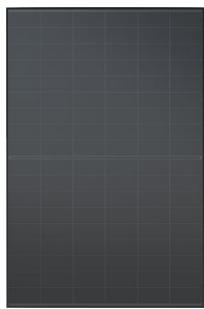
x2 Panels
Front
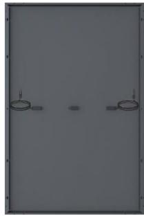
Back
x1 Micro-Inverter (including Wi-Fi transmitter)
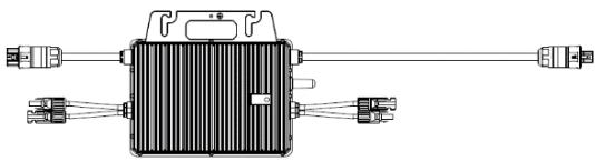
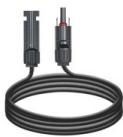
x4 DC extension cables

x1 Waterproof AC end cap
x2 1:1 Paper template
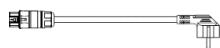
x1 10m cable with mains plug
Mounting structure
| X4 Triangle mounts | X2 Enhance bar |
| X2 M8*20 bolt (for micro-inverter) | X32 M8*20 bolt |
| X4 M8 * 120 bolt | X12 Expansion bolt M8*60 bolt |
| X4 Arc hanger | X4 U fixture |
4. Installation guide
Before Installation
Before connecting your solar kit to the mains, make the declaration for Auto-Consumption on the ENEDIS web portal.
During the registration process, ENEDIS will request the DIN VDE 0126-1-1 certificate of the micro-inverter. You can download this certificate by following this link:
www.mms-support.net/OTA/DG23BL0041_DIN_VDE0126.pdf
Make sure your home is equipped with a LINKY meter. If you do not yet have a LINKY meter, apply to ENEDIS web portal.
Your electrical installation must comply with the following standards
230V 16A 2P+T socket, connected to a good quality earth (earthing must be to standard)
Electrical circuit wired in 1.5mm2 and protected upstream by a 16A thermal-magnetic circuit breaker OR wired in 2.5mm2 and protected upstream by a 20A thermal-magnetic circuit breaker
Electrical circuit protected upstream by a 30mA earth leakage switch
For better production
Find a location that remains sunny throughout the day
Tilt the panels for better solar production
Give preference to a southern orientation

Please handle solar panels with caution and verify you have a socket within 10m from the kit.
SCREWDRIVER
PENCIL
DRILL/DRIVER
6mm ALLEN KEY
13mm WRENCH
Optimal mountings
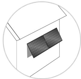

Inclined on a façade
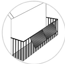

Attached to balcony
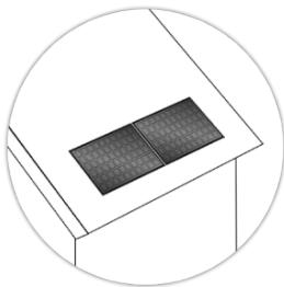

Flat on a sloping surface

On a low-rise building. Do not install it on the house roof.
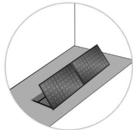

On the ground
STEP1:Structure assembly:Installation on the ground
The solar kit can be mounted horizontally on the ground.
Take out the solar kit and its accessories from the package. Verify that all the elements are present in the box.
Secure the triangle mounts (a) to the solar panel with M8*20 bolt, Mounting holes already predrilled on the solar panel frame.
3 Connect bar (a), (b) & (c) as shown with M8 * 20 bolts.
By securing the angle adjusting bar (c) to difference holes, solar panel can be tilted to different angle.

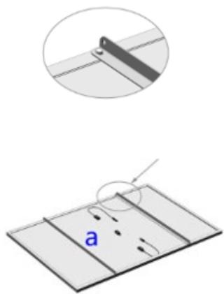

4 Connect the two triangle mounts together with enhance bar (d) to strengthen the whole mounting structure. Hole for enhance bar are the one located on the outermost.
5 Secure micro inverter to the solar panel. Mounting holes already predrilled on the solar panel frame.
6 Secure the solar panel to the ground through the M8*60 expansion bolts.
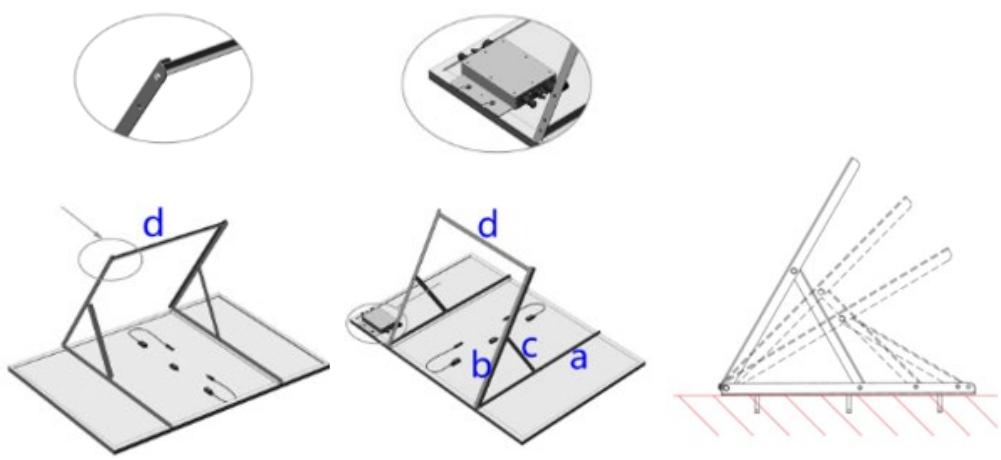

WARNING
- Choose installation location carefully and adhere to specified cooling requirements. Micro-inverter should be installed in a suitable position with good ventilation and no directly sunshine.
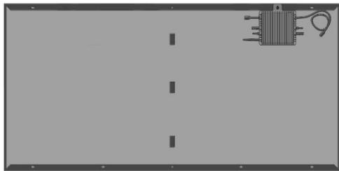
The optimum Micro-inverter fixation
STEP1 BIS : Structure assembly : Installation on thewall
The solar kit can be mounted vertically on the wall. The 5 first steps are the same as for Installation on the ground, please refer to STEP1 part.
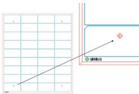
To help you prepare the place where it can be placed, You can use the 2 1 :1 drawings provided.
The micro inverter must be located at a maximum distance of 20m from your Wifi router, and with a maximum of one wall.

Position pattern
thesing
the 2 papers, provided in the box. They should be all aligned on your wall.

Mark the locations of the
future screws with a pencil and remove the papers.

Check that the hole pattern is
correct by placing the pre-assembled kit on top of your wall. You should see the pencil mark through the holes for wall mount.

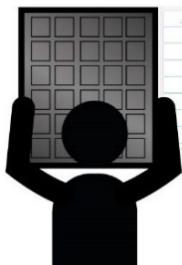
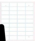
4 Secure the solar panel to the wall through the M8*60 expansion bolts.
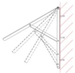
WARNING Choose installation location carefully and adhere to specified cooling requirements. Micro-inverter should be installed in a suitable position with good ventilation and no directly sunshine.
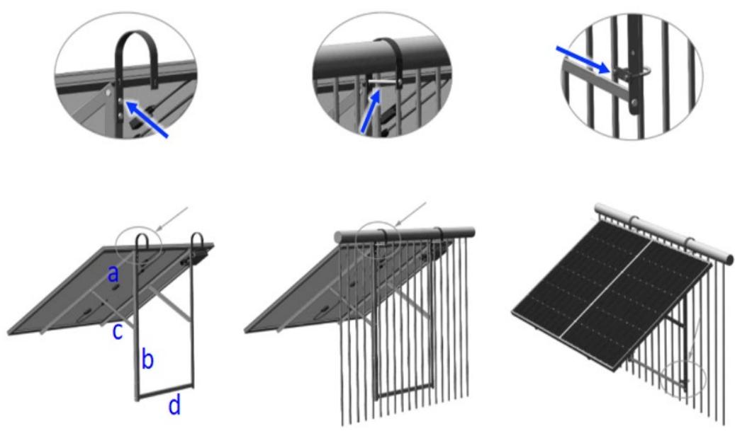
STEP 1 TER : Structure assembly : Installation on the balcony railing
The solar kit can be mounted to the railing of your balcony. The 5 first steps are the same as for Installation on the ground, please refer to STEP1 part.
The micro inverter must be located at a maximum distance of 20m from your Wifi router, and with a maximum of one wall.
1 Secure the two Arc hangers to Bar (b) of each of the triangle mount using M8*20 bolts.
Lift the solar panel assembly careful to outside of the balcony railing, and land the Arc hangers safely. Then lock the Arc hangers to the balcony railing using M8*120 bolts.
3 Lock the lower end of the solar panel assembly to the balcony railing using U fixtures, make sure that the U fixture land on above the enhance bar (d).
STEP 2 : Electrical connection of the system
Wiring diagram of each component
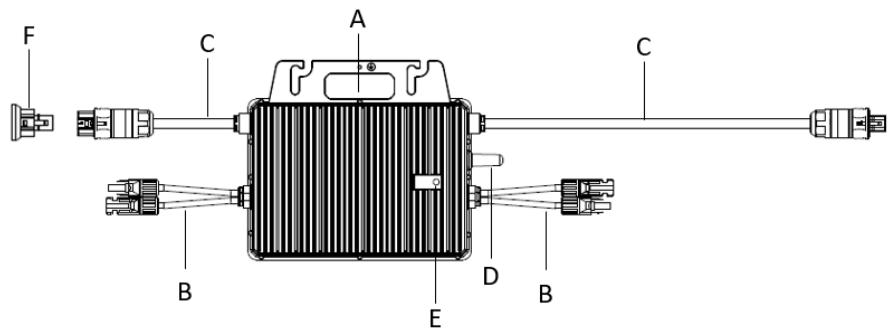
MICRO-INVERTER
A:Mounting Hole
C:AC Cables
E:StatusLEDLight
B:DC Cables
D: Antenna
F:AC end cap
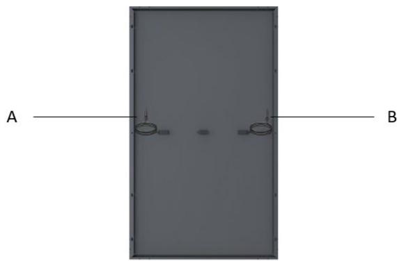
SOLAR PANEL
A: Male MC4 Connector
B: Female MC4 Connector
Before Electrical connection : Check the Installation Environment and Position
When choosing the position of installation, comply with the following conditions:
To avoid unwanted power derating due to an increase in the internal temperature of the inverter, do not expose it to direct sunlight.
To avoid overheating, always make sure the flow of air around the inverter is not blocked.
Do not install in places where gasses or flammable substances may be present.
Avoid electromagnetic interference that can compromise the correct operation of electronic equipment.
It's recommended to install microinverter on structures underneath the photovoltaic modules so that they work in the shade.
Use a mobile phone to check the Wi-Fi signal strength at the installation position. If the Wi-Fi signal is bad, try to install the microinverter at another position or move the Wi-Fi router.

DANGER
-
Before installation, check the micro-inverter to ensure absence of any transport or handling damage, which could affect insulation integrity or safety clearances.
-
Unauthorized removal of necessary protections, improper use, incorrect installation and operation may lead to serious safety and shock hazards or equipment damage.
-
Be aware that installation of this equipment includes risk of electric shock.
Optimal wire connections
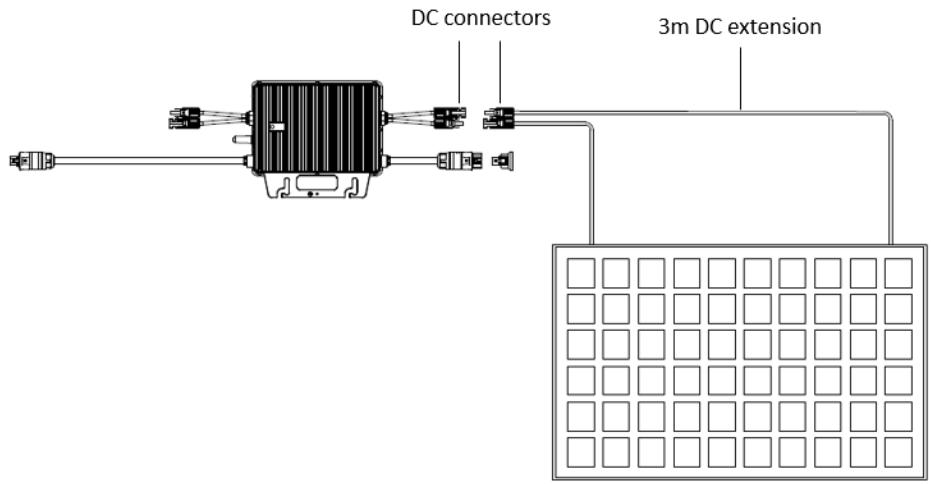
Final scheme of the system connection
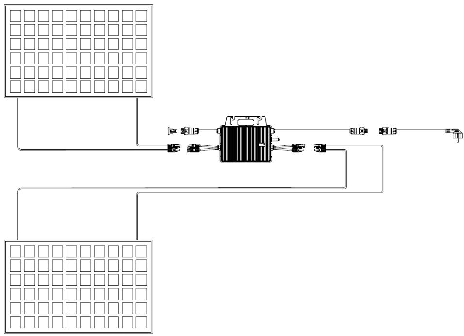
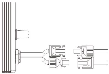
Connect the DC cables of each panel to the microinverter.

DANGER
- When the photovoltaic array is exposed to light, it provides a DC voltage to the inverter.
WARNING
-
Ensure that all DC cables are correctly wired and that none of the wires are pinched or damaged.
-
The maximum open circuit voltage of the PV modules included in this kit are designed to not exceed the specified maximum input DC voltage of the micro inverter. Do NOT use other components than ones provided in this kit.

CAUTION
-
If the DC cable is too short for installation, use a DC Extension Cable to connect PV modules to the microinverter.
-
Use MC4 compatible DC connectors in the inverter side of DC extension cable, included in this kit.
-
Contact aftersales service for the requirements of DC connectors in the module side of DC extension cable in case of needed.

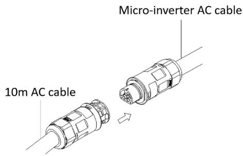
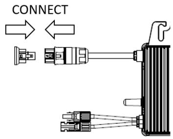
Plug the AC cable connector to the micro inverter.
Push in cable until it locks in.

Use a Waterproof Connector Protective Cap to make sure the unused AC connector to be closed.
Step 3. Start the System
1 Connect the AC cable plug to the 230V house socket.
2 Your system will start producing power after about a two-minute wait time.
The LED will flash green and red at start up.
If your micro-inverter is clicking in green color – the connection is well done and the production of electricity already started!


GREEN LIGHT BLINKING
The definition of LED light signals is shown as below:
| Status | Indicates | Solutions |
| Flashing Green (0.2-0.8) | Working normally | Your installation generates electricity |
| Flashing Green (0.2-3.8) | WiFi abnormally | Verify the wifi connection |
| Flashing Red | Working abnormally | Verify the electrical connections |
| Solid Red | Fault | Refer to troubleshooting section below |
5. Configuration of the micro-inverter and the app
The microinverter will directly connect the router (Wi-Fi Version). Users can use the Talent APP to monitor the microinverter.
Visit "Google Play" or "Apple Store" and "Talent Home". Download and install it in the mobile phone.

Talent Home
Register a new account in Talent Home.
Scan the QR code below to find the latest User Guidance of Talent Home.
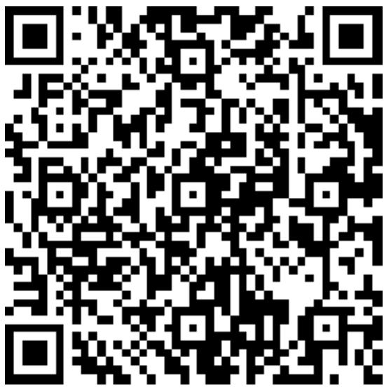
User Guidance of Talent Home
6. Troubleshooting
Some malfunctions can be easily resolved. Before calling customer service or a repairer, please consult the following table :
| Problem | Reason | Solution |
| No electricity production | Power failure | Check that there is no power failure |
| Incorrect electrical connection | Check that cables are correctly connected |
| Micro-inverter or solar panel is damaged | Contact aftersales department |
| Insufficient sunshine | Move the installation to a sunnier location |
| Installation is not connected to the household electrical system | Plug the installation to the house socket |
| Solid Red LED light on microinverter | Fault | Contact aftersales department |
If you have any questions, please contact our customer service department at sav@market-maker.fr.
Market Maker Brand Licensing, hereby declares that this equipment, conforms to the essential requirements and other relevant provisions of Directive 2014/53/UE.
The declaration of Conformity can be viewed at the following address:
www.mms-support.net/OTA/ECDMMBL SI-2KIT410-001.pdf
8. Warranty
SUPPORT MODE
For micro-inverters and solar panels products (excluding structures and screws which are guaranteed two (2) years), from the SIRIUS brand, we offer the Customer a commercial guarantee for a period of twelve (12) years from the delivery date of the goods during which the product will be replaced.
For any support request, please contact the after-sales service by email at sav@market-maker.fr.
You will then be asked for the defective part and the original invoice attesting to the payment of the product.
We may ask you for photos of your appliance.
It is also important to provide a photo of the appliance identification label, usually placed under the appliance.
Within the framework of the implementation of the legal guarantee of conformity, a non-conforming or defective product may be, at your choice, repaired or replaced.
If the product is repaired, and provided that the legal guarantee period is still running, you will benefit from an extension of guarantee of 6 additional months.
If you choose to repair the product, when repair is not possible, we will replace the product. This new product will then be covered by a new 2-year guarantee.
DEFECTS ON UNPACKING
If, upon unpacking, the product or the appliance turns out to contain a defect that hinders its usability for the purpose for which it was designed and manufactured, please contact the after-sales service within 72 working hours.
GUARANTEE EXCLUSIONS
The guarantee does not apply in the event of accidental material damage and, in particular, does not cover deterioration and failure due to:
- Improper installation (incorrect assembly or assembly contrary to the instructions in the user manual) or improper maintenance of the product, or negligence including :
- Improper use of the equipment or failure to follow the instructions contained in the user manual;
- Faulty storage;
- Transport or mishandling;
- Lightning, flood, fire, power surge, shock, poor ventilation, fall, discoloration due to light, burning, humidity, excessive heating without
humidifier, unevenness of the floor or presence of insects, destruction due to the intervention of a third party or animals;
- Repairs carried out and / or any intervention on the equipment and / or opening of the equipment by a person not authorized by the manufacturer;
- Maintenance, repair or replacement of parts due to normal wear and tear (example : impact) ;
- Lack of maintenance or maintenance contrary to the instructions for use and maintenance specified by the seller and/or by the instructions for use and maintenance accompanying the product;
- Modification of the construction and original characteristics of the guaranteed product;
- Corrosion, oxidation, improper connection or external power supply problems;
An event of force majeure;
Without this list being limitative.
The guarantee only covers the right to repair or replace the guaranteed product.
Thus, consequential damages resulting from failure or deterioration are not covered by the guarantee, including:
- The costs of commissioning, adjustment, cleaning;
- Damage of any kind resulting from the unavailability of the guaranteed product during the period between the deterioration or failure and the repair or replacement of the guaranteed product.
OTHER EXCLUSIONS
- Damage and failures falling under the specific exclusions provided for in the manufacturer's warranty for the guaranteed product, as mentioned in the product's user manual;
- Deterioration of an aesthetic nature;
- Guaranteed products that the customer is unable to return or those returned without their accessories;

SIRIUS
Merci!
Market Maker Brand Licensing declares that the present is a great opportunity for the market to be licensed in the United States.