UX-S59 - Micro component system VICTOR - Free user manual and instructions
Find the device manual for free UX-S59 VICTOR in PDF.

| Product type | Micro component system |
| Brand | Victor |
| Model | UX-S59 |
| Output power | 120 W (60 W + 60 W) at 6 Ω (10% distortion) |
| Speaker impedance | 6 Ω - 16 Ω |
| AUX audio input | 400 mV / 50 kΩ |
| FM tuner section | 87.50 MHz - 108.00 MHz |
| AM (MW) tuner section | 522 kHz - 1,629 kHz |
| Signal-to-noise ratio (CD player) | 85 dB |
| Wow and flutter (CD) | Imperceptible |
| Power supply | AC 230 V, 50 Hz |
| Power consumption | 125 W operating, 0.9 W standby |
| Dimensions (main unit) | 175 mm × 232 mm × 412 mm (L × H × P) |
| Weight (main unit) | 6.6 kg |
| Speaker type | 2-way, bass reflex |
| Speakers | Woofer: 10 cm cone × 1, Tweeter: 4 cm cone × 1 |
| Dimensions (speaker) | 144 mm × 231 mm × 201 mm (L × H × P) |
| Weight (speaker) | 2.0 kg each |
| Maintenance and cleaning | Unplug the device before cleaning. Use a soft, dry cloth. Do not use solvents. |
| Safety | Do not open the device. Have all repairs carried out by qualified personnel. Use identical replacement parts. |
Frequently Asked Questions - UX-S59 VICTOR
User questions about UX-S59 VICTOR
0 question about this device. Answer the ones you know or ask your own.
Ask a new question about this device
Download the instructions for your Micro component system in PDF format for free! Find your manual UX-S59 - VICTOR and take your electronic device back in hand. On this page are published all the documents necessary for the use of your device. UX-S59 by VICTOR.
USER MANUAL UX-S59 VICTOR
| Amplifier section | Output Power | 120 W (60 W + 60 W) at 6 Ω (10% THD) | |
| Speakers/Impedance | 6 Ω - 16 Ω | ||
| Audio Input AUX | 400 mV/50 kΩ | ||
| Tuner section | FM tuning range | 87.50 MHz - 108.00 MHz | |
| AM (MW) tuning rangeDynamic range | 522 kHz - 1 629 kHz | ||
| CD player section | 85 dB | ||
| Signal-to-noise ratio | 85 dB | ||
| Wow and flutter | Immeasurable | ||
| General | Power requirement | AC 230 V, 50 Hz | |
| Power consumption | 125 W (at operation)0.9 W (on standby) | ||
| Dimensions (approx.) | 175 mm × 232 mm × 412 mm (W/H/D) | ||
| Mass (approx.) | 6.6 kg | ||
| Speakers | Type | 2-way Bass reflex | |
| Speaker units | Woofer | 10 cm cone × 1 | |
| Tweeter | 4 cm cone × 1 | ||
| Impedance | 6 Ω | ||
| Dimensions (approx.) | 144 mm × 231 mm × 201 mm (W/H/D) | ||
| Mass (approx.) | 2.0 kg each | ||
Designs & specifications are subject to change without notice
SECTION 1 PRECAUTIONS
1.1 Safety Precautions
(1) This design of this product contains special hardware and many circuits and components specially for safety purposes. For continued protection, no changes should be made to the original design unless authorized in writing by the manufacturer. Replacement parts must be identical to those used in the original circuits. Services should be performed by qualified personnel only.
(2) Alterations of the design or circuitry of the product should not be made. Any design alterations of the product should not be made. Any design alterations or additions will void the manufacturers warranty and will further relieve the manufacture of responsibility for personal injury or property damage resulting therefrom.
(3) Many electrical and mechanical parts in the products have special safety-related characteristics. These characteristics are often not evident from visual inspection nor can the protection afforded by them necessarily be obtained by using replacement components rated for higher voltage, wattage, etc. Replacement parts which have these special safety characteristics are identified in the Parts List of Service Manual. Electrical components having such features are identified by shading on the schematics and by (▲) on the Parts List in the Service Manual. The use of a substitute replacement which does not have the same safety characteristics as the recommended replacement parts shown in the Parts List of Service Manual may create shock, fire, or other hazards.
(4) The leads in the products are routed and dressed with ties, clamps, tubings, barriers and the like to be separated from live parts, high temperature parts, moving parts and/or sharp edges for the prevention of electric shock and fire hazard. When service is required, the original lead routing and dress should be observed, and it should be confirmed that they have been returned to normal, after reassembling.
(5) Leakage shock hazard testing
After reassembling the product, always perform an isolation check on the exposed metal parts of the product (antenna terminals, knobs, metal cabinet, screw heads, headphone jack, control shafts, etc.) to be sure the product is safe to operate without danger of electrical shock. Do not use a line isolation transformer during this check.
- Plug the AC line cord directly into the AC outlet. Using a "Leakage Current Tester", measure the leakage current from each exposed metal parts of the cabinet, particularly any exposed metal part having a return path to the chassis, to a known good earth ground. Any leakage current must not exceed 0.5mA AC (r.m.s.).
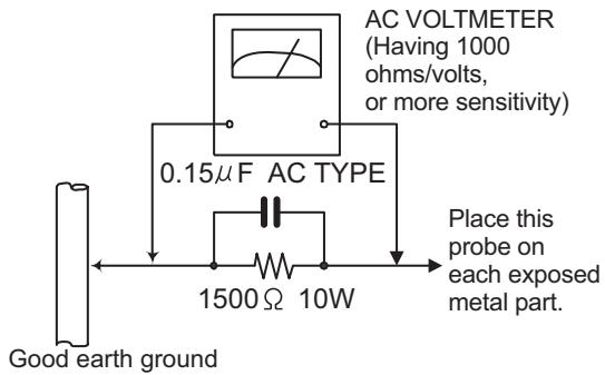
• Alternate check method
Plug the AC line cord directly into the AC outlet. Use an AC voltmeter having, 1,000Ω per volt or more sensitivity in the following manner. Connect a 1,500Ω 10W resistor paralleled by a 0.15μF AC-type capacitor between an exposed metal part and a known good earth ground.
Measure the AC voltage across the resistor with the AC
voltmeter.
Move the resistor connection to each exposed metal part, particularly any exposed metal part having a return path to the chassis, and measure the AC voltage across the resistor. Now, reverse the plug in the AC outlet and repeat each measurement. Voltage measured any must not exceed 0.75 V AC (r.m.s.). This corresponds to 0.5 mA AC (r.m.s.).
text_image
AC VOLTmeter (Having 1000 ohms/volts, or more sensitivity) 0.15μF AC TYPE 1500 Ω 10W Place this probe on each exposed metal part. Good earth ground1.2 Warning
(1) This equipment has been designed and manufactured to meet international safety standards.
(2) It is the legal responsibility of the repairer to ensure that these safety standards are maintained.
(3) Repairs must be made in accordance with the relevant safety standards.
(4) It is essential that safety critical components are replaced by approved parts.
(5) If mains voltage selector is provided, check setting for local voltage.
1.3 Caution
Burrs formed during molding may be left over on some parts of the chassis.
Therefore, pay attention to such burrs in the case of pre-forming repair of this system.
1.4 Critical parts for safety
In regard with component parts appearing on the silk-screen printed side (parts side) of the PWB diagrams, the parts that are printed over with black such as the resistor ( ), diode ( ) and ICP ( ) or identified by the " " mark nearby are critical for safety. When replacing them, be sure to use the parts of the same type and rating as specified by the manufacturer.
(This regulation dose not Except the J and C version)
1.5 Safety Precautions (U.K only)
(1) This design of this product contains special hardware and many circuits and components specially for safety purposes. For continued protection, no changes should be made to the original design unless authorized in writing by the manufacturer. Replacement parts must be identical to those used in the original circuits.
(2) Any unauthorised design alterations or additions will void the manufacturer's guarantee; furthermore the manufacturer cannot accept responsibility for personal injury or property damage resulting therefrom.
(3) Essential safety critical components are identified by ( ) on the Parts List and by shading on the schematics, and must never be replaced by parts other than those listed in the manual. Please note however that many electrical and mechanical parts in the product have special safety related characteristics. These characteristics are often not evident from visual inspection. Parts other than specified by the manufacturer may not have the same safety characteristics as the recommended replacement parts shown in the Parts List of the Service Manual and may create shock, fire, or other hazards.
(4) The leads in the products are routed and dressed with ties, clamps, tubings, barriers and the like to be separated from live parts, high temperature parts, moving parts and/or sharp edges for the prevention of electric shock and fire hazard. When service is required, the original lead routing and dress should be observed, and it should be confirmed that they have been returned to normal, after re-assembling.
1.5.1 Warning
(1) Service should be performed by qualified personnel only.
(2) This equipment has been designed and manufactured to meet international safety standards.
(3) It is the legal responsibility of the repairer to ensure that these safety standards are maintained.
(4) Repairs must be made in accordance with the relevant safety standards.
(5) It is essential that safety critical components are replaced by approved parts.
(6) If mains voltage selector is provided, check setting for local voltage.

CAUTION Burrs formed during molding may be left over on some parts of the chassis. Therefore, pay attention to such burrs in the case of preforming repair of this system.
SECTION 2 SPECIFIC SERVICE INSTRUCTIONS
This service manual does not describe SPECIFIC SERVICE INSTRUCTIONS.
SECTION 3
DISASSEMBLY
3.1 Disassembly of Right plate left plate Top cover
- Replacement of the fuses and AMP IC .THMS RES. Transistor. 7808 IC.
3.1.1 Replacing the fuses (See Fig.1)
- Prior to performing the following procedure, remove right plate, left plate, top cover.
(1) Replace the fuses inside.
Caution:
Be sure to use fuses with the specified
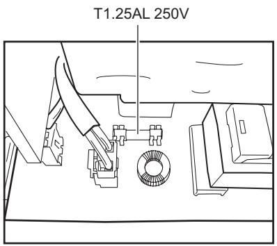
text_image
T1.25AL 250VFig.1
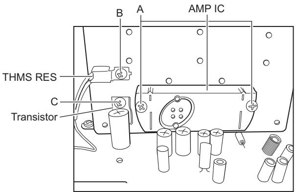
3.1.2 Replacing the AMP IC (See Fig.2)
- Prior to performing the following procedure, remove the right plate, left plate, top cover.
(1) Remove the two screws A from the heat sink between AMP IC.
(2) Remove the solder fixing the AMP IC.
3.1.3 Replacing the THMS RES (See Fig.2)
- Prior to performing the following procedure, remove right plate, left plate, top cover.
(1) Remove the one screw B from head sink.
(2) Remove the solder fixing THMS RES.
3.1.4 Replacing the transistor (See Fig.2)
(1) Remove the one screw C from head sink.
(2) Remove the solder fixing the Transistor.
3.1.5 Replacing the 7808 IC (See Fig.3)
(1) Remove the one screw D from head sink.
(2) Remove the solder fixing 7808 IC.
text_image
B A AMP IC THMS RES C TransistorFig.2
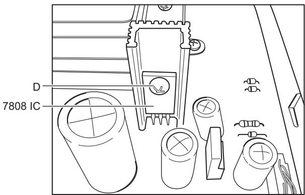
text_image
D 7808 ICFig.3
3.1.6 Removing the transformer cover (See Fig.4)
(1) Remove the ten screws E from top cover.
(2) Take off transformer cover from rear plate.
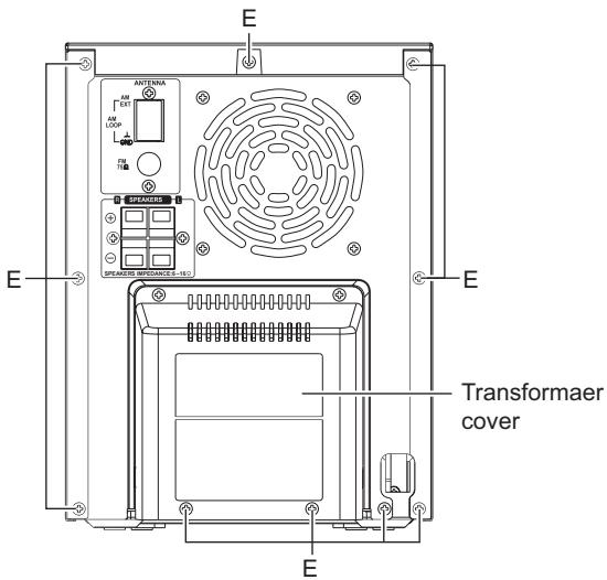
text_image
E ANTENIA AV OUT AW LOOP FS TRB SPEAKER REFERENCE=NEO E E Transformer cover EFig.4
3.1.7 Removing the right plate (See Fig.5)
(1) Remove the two screws F from right plate.
(2) Take off right plate from main body.
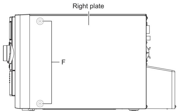
text_image
Right plate FFig.5
3.1.8 Removing the left plate (See Fig.6)
(1) Remove the two screws G from left plate.
(2) Take off left plate from main body.
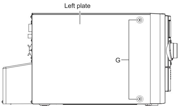
text_image
Left plate GFig.6
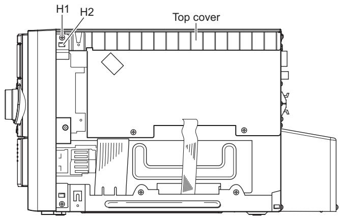
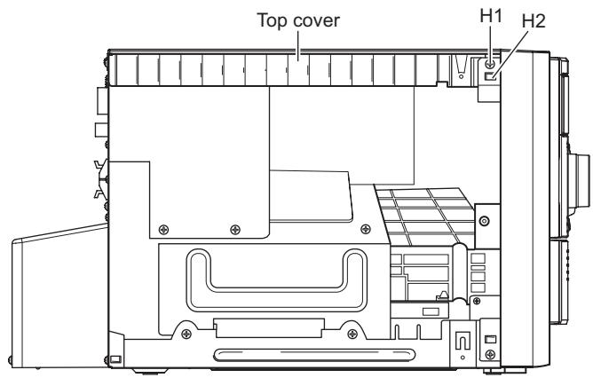
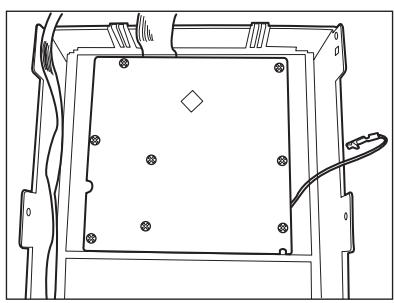
3.1.9 Removing the top cover (See Fig.7 to 9)
(1) Remove the two screws H1 (See Fig.7,8).
(2) Disengage the claws H2 on both side of the front cabinet (See Fig.7, 8).
(3) Rotate top cover and let's away from main body (See Fig.9).
Caution:
When you rotate top cover, must to slow raise, Don't to destroy the two claws of front cabinet.
text_image
H1 H2 Top coverFig.7
text_image
Top cover H1 H2Fig.8
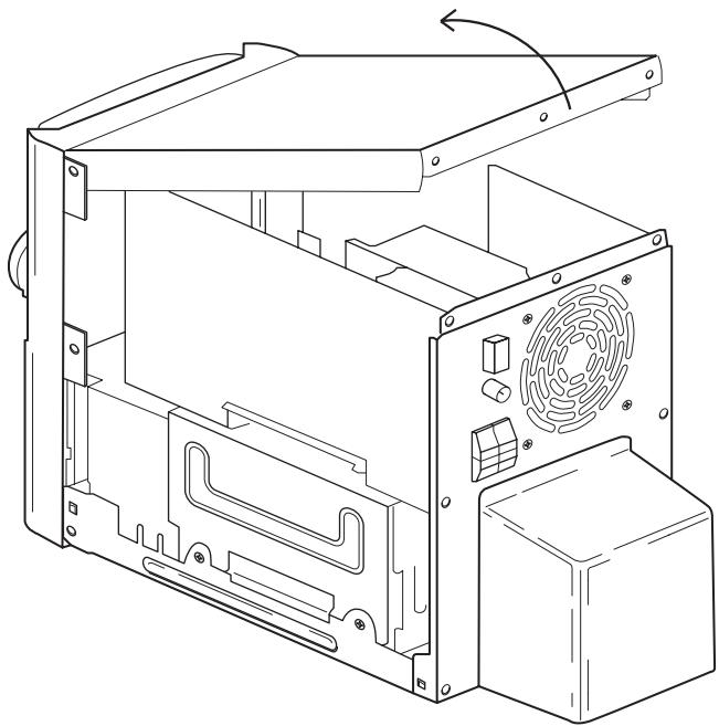
natural_image
Technical line drawing of a computer tower case with visible internal components and mounting holes (no text or labels)Fig.9
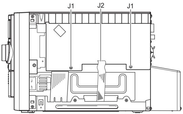
3.1.10 Removing the main board (See Fig.10 to 13)
(1) Remove the two screws J1. (See Fig.10)
(2) Disconnect the FFC cables J2 from the connector CN661 on main board. (See Fig.10)
(3) Disconnect the FFC cables J3 from the connector CN402 on main board. (See Fig.11)
(4) Disconnect the FFC cables J4 from the connector CN681 on main board. (See Fig.12)
(5) Remove main board from AMP board after disconnect the connector J319 and CN601. (SeeFig.13)
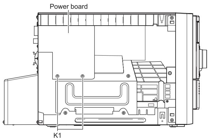
3.1.11 Removing the power board (See Fig.14 to 16)
(1) Remove the two screws K1 from CD mechanism cover and power board. (See Fig.14)
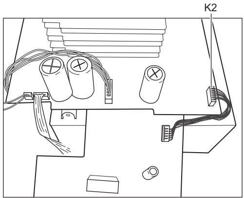
(2) Disconnect the wire K2 from the connector CN102 on the AMP board. (See Fig.15)
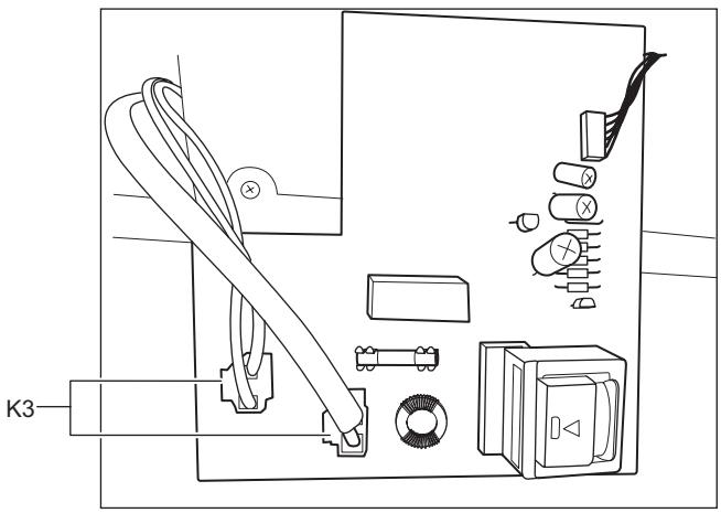
(3) Disconnect the two wire K3 from the connector CN901 and CN902. (See Fig.16)
text_image
Power board K1Fig.14
natural_image
Technical line drawing of an electronic component with capacitors, wires, and connectors (no text or symbols)Fig.15
natural_image
Technical line drawing of a mechanical or electronic device with labeled components (no readable text or symbols)Fig.16
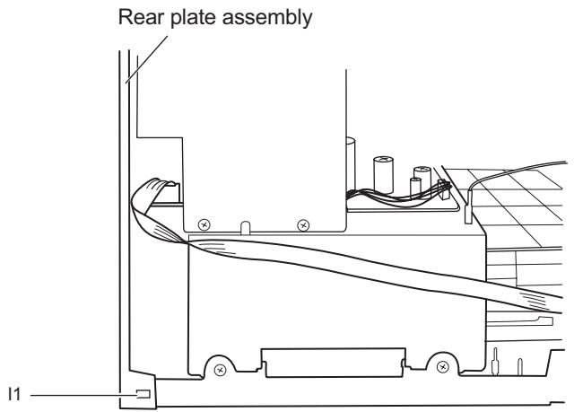
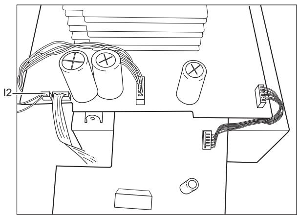
3.1.12 Removing the rear plate assembly (See Fig.17 to 18)
(1) Disengage the claws I1 on both sides of bottom plate. (See Fig.17)
(2) Disconnect the wire I2 from the connector CN105 on the AMP board. (See Fig.18)
text_image
Rear plate assembly I1Fig.17
natural_image
Technical line drawing of an electrical connector with batteries, wires, and connectors (no text or symbols)Fig.18
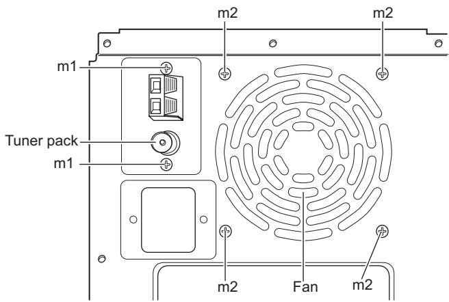
3.1.13 Removing the fan (See Fig.19)
(1) Removing the four screws M2.
3.1.14 Removing the tuner pack (See Fig.19)
(1) Removing the two screws M1.
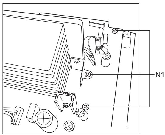
3.1.15 Removing the AMP board (See Fig.20 to 22)
(1) Removing the three screws N1 of the AMP board between CD mechanism cover. (See Fig.20)
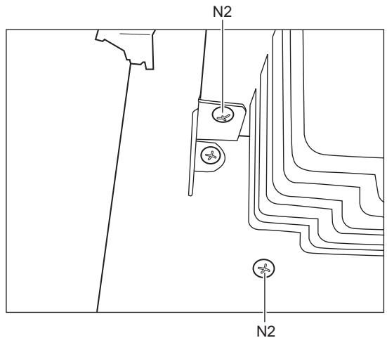
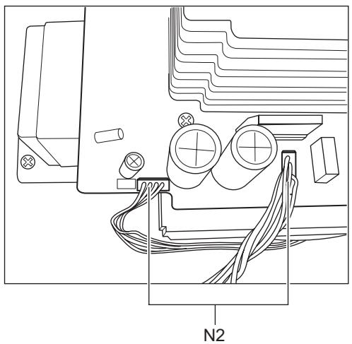
(2) Removing the two screws N2 of the AMP board between CD mechanism cover. (See Fig.21)
(3) Disconnect the two wires N3 from the connector CN101 and CN204 on the AMP board. (See Fig.22)
natural_image
Technical line drawing of a mechanical assembly with components like gears, bolts, and fasteners (no text or symbols)Fig.20
text_image
N2 N2Fig.21
natural_image
Technical line drawing of a mechanical assembly with labeled component N2 (no text or symbols beyond label)Fig.22
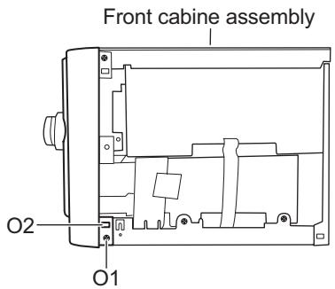
3.1.16 Removing the front cabinet (See Fig.23 to 25)
(1) Removing the two screws O1. (See Fig.23, 24)
(2) Disengage the claws O2 on both side of the bottom plate. (See Fig.23, 24)
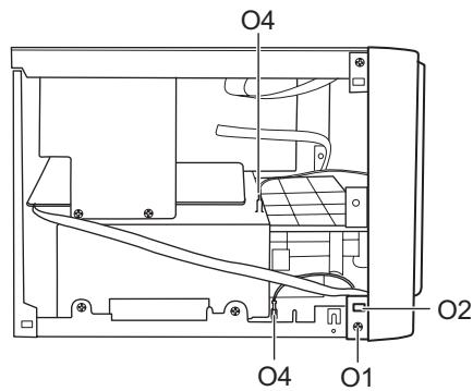
(3) Pull out two connect wire 04 separate on CD mechanism cover and bottom plate. (See Fig.24)
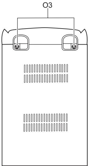
(4) Remove the two screws O3. (See Fig.25)
text_image
Front cabine assembly O2 O1Fig.23
text_image
O4 O2 O4 O1Fig.24
natural_image
Simple line drawing of a battery with two side tabs and internal circuit-like patterns (no text or symbols)Fig.25
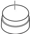
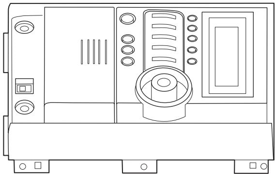
3.1.17 Removing the volume knob (See Fig.26, 27)
(1) Place the flat screw driver top in hole front cabinet and the key board. (See Fig.26)
(2) Hand hold volume knob, Use the flat screw driver prop up volume knob bottom surface and let's move out of the Front cabinet. (See Fig.27)
natural_image
Technical line drawing of a mechanical component with mounting holes and wiring (no text or symbols)Fig.26
Volume knob
natural_image
Line drawing of a portable electronic device with front panel, buttons, and control panel (no text or symbols)Fig.27
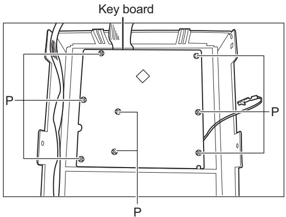
3.1.18 Removing the key board (See Fig.28)
(1) Remove the eight screws P from the front cabinet and the key board.
text_image
Key board P P PFig.28
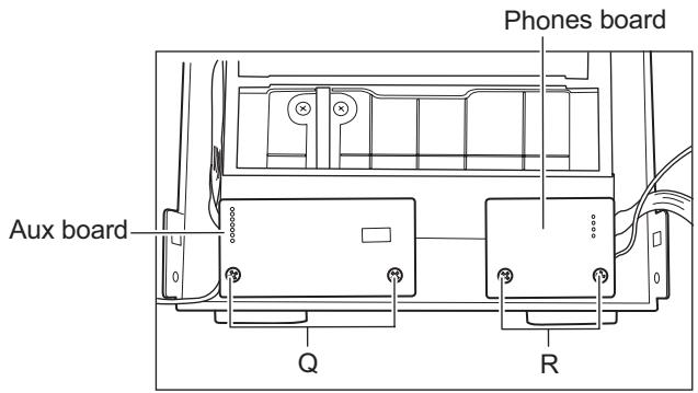
3.1.19 Removing the AUX board (See Fig.29)
(1) Remove the two screws Q from the front cabinet and the aux board.
3.1.20 Removing the phones board (See Fig.29)
(1) Remove the two screws R from the front cabinet and the phones board.
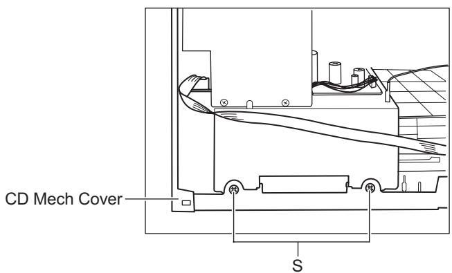
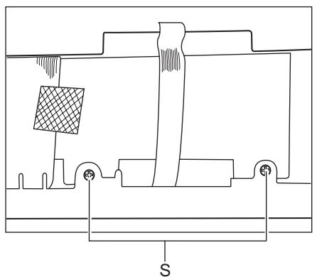
3.1.21 Removing the CD mechanism cover (See Fig.30, 31)
(1) Remove the four screws S.
text_image
Phones board Aux board Q RFig.29
text_image
CD Mech Cover SFig.30
natural_image
Technical line drawing of a mechanical assembly with no visible text or symbolsFig.31
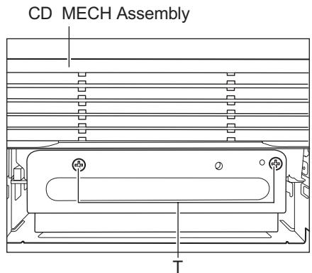
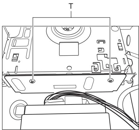
3.1.22 Removing the CD mechanism Assembly (See Fig.32, 33)
(1) Remove the two screws T from the CD mechanism-F and CD mechanism assembly. (See Fig.32)
(2) Remove the two screws T from the CD mechanism-B and CD mechanism assembly. (See Fig.33)
(3) Take out CD mechanism assembly from the CD mechanism-F between the CD mechanism-B.
text_image
CD MECH Assembly TFig.32
natural_image
Technical line drawing of a mechanical device with labeled component T and cable (no text or symbols)Fig.33
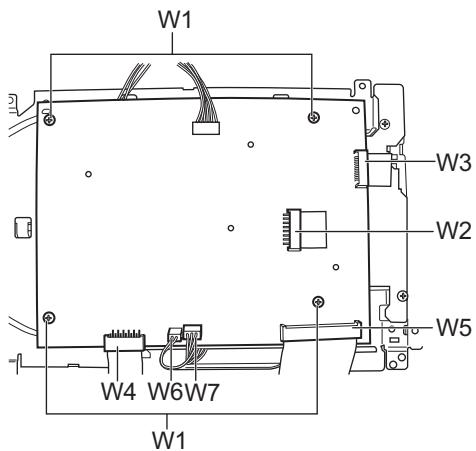
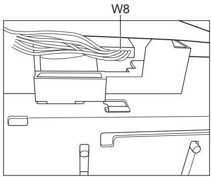
3.1.23 Removing the CD board (See Fig.34, 35)
(1) Removing the four screws W1 from the CD board and CD mechanism holder. (See Fig.34)
(2) Disconnect the FFC cable W2 from the connector CN701 on the CD board. (See Fig.34)
(3) Disconnect the FFC cable W3 from the connector JW756 on the CD board. (See Fig.34)
(4) Disconnect the FFC cable W4 from the connector CN802 on the CD board. (See Fig.34)
(5) Disconnect the FFC cable W5 from the connector CN801 on the CD board. (See Fig.34)
(6) Disconnect the wire W8 from connector of the CD mechanism "CMS". (See Fig.35)
text_image
W1 W3 W2 W5 W4 W6W7 W1Fig.34
text_image
W8Fig.35
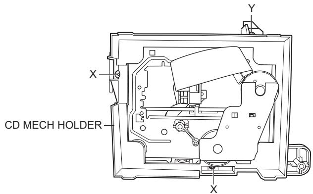
3.1.24 Removing the CD mechanism holder (See Fig.36)
(1) Remove the three screws X from the CD mechanism holder and the CD mechanism.
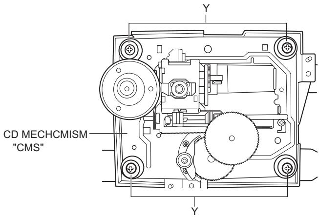
3.1.25 Removing the CD mechanism "CMS" (See Fig.36, 37)
(1) Remove the four screws Y from the CD mechanism holder.
(2) Take out CD mechanism "CMS".
Caution:
Don't touch laser camera lens and PCB.
text_image
CD MECH HOLDER X Y XFig.36
text_image
CD MECHCMISM "CMS"Fig.37
SECTION 4
ADJUSTMENT
This service manual does not describe ADJUSTMENT.
SECTION 5
TROUBLESHOOTING
This service manual does not describe TROUBLESHOOTING.
PARTS LIST
[ UX-S59 ]
* All printed circuit boards and its assemblies are not available as service parts.
Area suffix
B U.K.
E ---- Continental Europe
EN ---- Northern Europe
EV ---- Eastern Europe
- Contents -
Exploded view of general assembly and parts list (Block No.M1) 3-2
CD mechanism assembly and parts list (Block No.MB) 3-5
Electrical parts list (Block No.01\~06) 3-7
Packing materials and accessories parts list (Block No.M3) 3-14
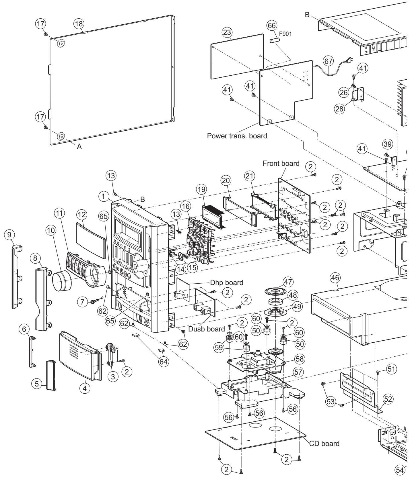
Exploded view of general assembly and parts list
Block No. M 1 M M
text_image
Exploded view diagram of a power trans. board assembly with numbered components and labeled parts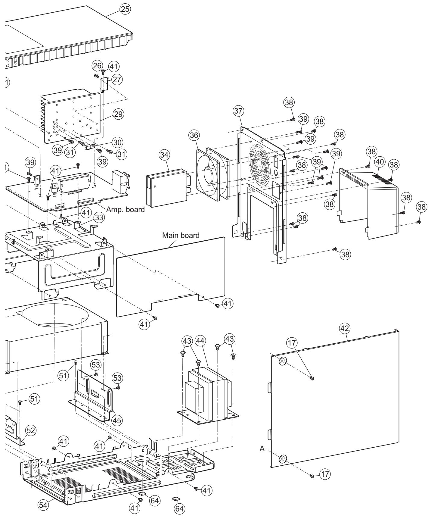
General Assembly
Block No. [M][1][M][M]
| △ Symbol No. | Part No. | Part Name | Description | Local |
| 1 | BI1080670202V1 | FRONT CABINET | USB | |
| 2 | BIBT000418 | TAPPING SCREW | (x23) | |
| 3 | BI1081770101X1 | SLIDE BLOCK | ||
| 4 | BI1080690101V1 | CD DOOR | ||
| 5 | BI1080770201V1 | BOTTOM LENS R | ||
| 6 | BI1080780201V1 | BOTTOM LENS L | ||
| 7 | BI202904010201 | CD DOOR SPRING | ||
| 8 | BI1080750201V1 | TOP LENS R | ||
| 9 | BI1080760201V1 | TOP LENS L | ||
| 10 | BI1080800101V1 | VOLUME KNOB | ||
| 11 | BI1080820101V1 | KEY PANEL | ||
| 12 | BI1080720201V1 | WINDOW LENS | ||
| 13 | BIKT000606 | TAPPING SCREW | (x2) | |
| 14 | BI1080730201V1 | POWER LENS | ||
| 15 | BI1080740101V1 | LENS | ||
| 16 | BI1080810101V1 | FUNCTION KEY | ||
| 17 | BIRT000608B1W | TAPPING SCREW | (x4) | |
| 18 | BI2028960101W1 | LEFT PLATE | ||
| 19 | BI2702191V | LCD | TCM-4217 | |
| 20 | BI680FSG505L | LED BACK LIGHT | ||
| 21 | BI1080840101V1 | LCD HOLDER | ||
| 23 | BI302209010101 | PCB PLATE | ||
| 25 | BI1080680101V1 | TOP COVER | ||
| 26 | BIRT000611B3 | TAPPING SCREW | (x2) | |
| 27 | BI2029350101W1 | HEATSINK BKT | B | |
| 28 | BI2029340101W1 | HEATSINK BKT | F | |
| 29 | BI202903010101 | HEATSINK | ||
| 30 | BI2029330101W1 | HEAT RES BKT | ||
| 31 | BIBT0006091 | TAPPING SCREW | (x2) | |
| 33 | BI2029000101W1 | CD MECH COVER | ||
| 34 | BIZ25094901VV | TUNER PACK | ||
| 36 | BI2400241V | DC FAN | DC12V | |
| 37 | BI2028950301W1 | REAR PLATE | ||
| 38 | BIRM000603S3 | TAPPING SCREW | (x12) | |
| 39 | BIRT000617B3 | TAPPING SCREW | (x11) | |
| 40 | BI1080790101V1 | TRANS. COVER | ||
| 41 | BIBT000604S3 | TAPPING SCREW | (x14) | |
| 42 | BI2028970101W1 | RIGHT PLATE | ||
| 43 | BIPMW001101S3 | TAPPING SCREW | (x4) | |
| △ 44 | BI211041011001W | POWER TRANS. | ||
| 45 | BI2028990101W1 | CD MECH BRAKET | ||
| 46 | BI251051000300V | 5CD CHANGER | ||
| 47 | BI2029060101W1 | CD CHUCK PLATE | ||
| 48 | BI202930010101 | CD MAGET | ||
| 49 | BI1081030101V1 | CD CHUCK | ||
| 50 | BI301942010101 | CUSHION RUBBER | RED(x2) | |
| 51 | BIRT000604S3 | TAPPING SCREW | (x6) | |
| 52 | BI2028980101W1 | CD MECHA BKT | ||
| 53 | BIRT000603P3 | TAPPING SCREW | (x4) | |
| 54 | BI2028940101W1 | BOTTOM PLATE | ||
| 56 | BIBT000405S3 | TAPPING SCREW | (x3) | |
| 57 | BI1080830101V1 | CD MECH HOLDER | ||
| 58 | BI251011003200V | CD MECHANISM | CMS-B35SG6U | |
| 59 | BI301943010101 | CUSHION RUBBER | GREEN(x2) | |
| 60 | BI300856010101 | WASHER | (x4) | |
| 62 | BIKT0006-06B3 | TAPPING SCREW | (x4) | |
| 64 | BI302197010101 | RUBBER FOOT | (x4) | |
| 65 | BI302193010101 | CD DOOR RUBBER | (x2) | |
| △ 66 | BI403131 | FUSE | 2.5A/250V F901 | |
| △ 67 | BI1401731V | POWER CORD |
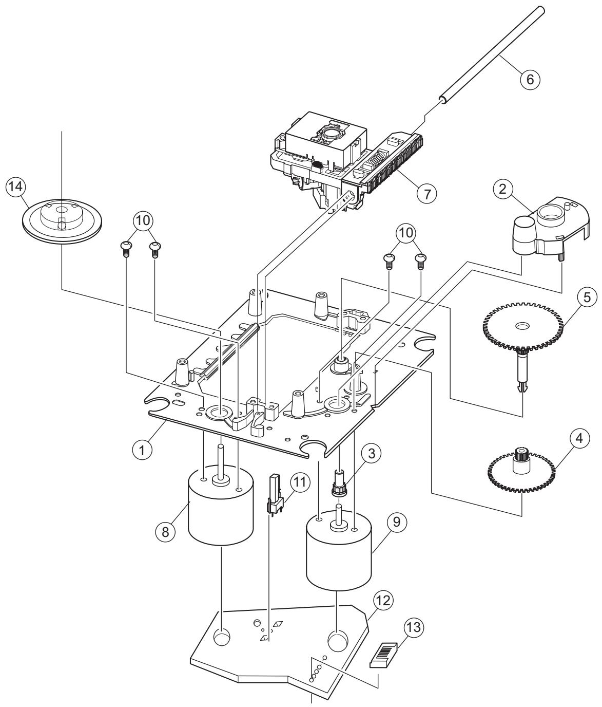
CD mechanism assembly and parts list
Block No. M B M M
text_image
Exploded view diagram of a mechanical assembly with numbered components for identificationThe parts without symbol number are not service.
CD mechanism
Block No. [M][B][M][M]
| △ Symbol No. | Part No. | Part Name | Description | Local |
| 1 | BIAJ7000601E | CHASSIS | ||
| 2 | BIAJ6600601G | GEAR COVER | ||
| 3 | BIAJ6600601D | GEAR | A | |
| 4 | BIAJ6600601B | GEAR | B | |
| 5 | BIAJ6600601F | GEAR | C | |
| 6 | BIAJ7000601A | SHAFT | ||
| 7 | BISOHAAN | PICK UP | ||
| 8 | BIAJ3100601B | SPINDLE MOTOR | ||
| 9 | BIAJ3100601A | FEED MOTOR | ||
| 10 | BIAJ6000601D | SCREW | M2XL3(x4) | |
| 11 | BI3409000174 | LEAF SWITCH | ||
| 12 | BIAJ4100601E | SUB PCB | ||
| 13 | BIAJ3700601A | CONNECTOR | ||
| 14 | BIAJ7500601K | TURN TABLE |
Electrical parts list Main board
| △ Symbol No. | Part No. | Part Name | Block No. [0][1] | |
| Description | Local | |||
| IC401 | S3C825A | IC | BI118131 | |
| IC402 | PST3429UL | IC | BI117161 | |
| IC501 | BA4558F | IC | BI103952 OP/AMP | |
| IC601 | BD3881FV | IC | BI112721 | |
| Q401 | DTC114YK | TRANSISTOR | BI2DTC114YKA011 | |
| Q402 | 2SC3052 | TRANSISTOR | BI2SC3052FA013V | |
| Q403 | 2SC3052 | TRANSISTOR | BI2SC3052FA013V | |
| Q404 | 2SC3052 | TRANSISTOR | BI2SC3052FA013V | |
| Q405 | 2SA1980G | TRANSISTOR | BI2SA1980GP000 V | |
| Q501 | KTC3199GR | TRANSISTOR | BI2KTC3199GP00 0 | |
| Q502 | KTC3199GR | TRANSISTOR | BI2KTC3199GP00 0 | |
| Q602 | 2SC3052 | TRANSISTOR | BI2SC3052FA013V | |
| Q603 | 2SC3052 | TRANSISTOR | BI2SC3052FA013V | |
| Q683 | KTA1267GR | TRANSISTOR | BI2KTA1267GP000 | |
| Q684 | 2SC3052 | TRANSISTOR | BI2SC3052FA013V | |
| D401 | 1SS133 | FR DIODE | BI31SS133M000V 7 | |
| D402 | 1SS133 | FR DIODE | BI31SS133M000V 7 | |
| D403 | 1SS133 | FR DIODE | BI31SS133M000V 7 | |
| D404 | 1SS133 | FR DIODE | BI31SS133M000V 7 | |
| D405 | 1SS133 | FR DIODE | BI31SS133M000V 7 | |
| D406 | 1SS133 | FR DIODE | BI31SS133M000V 7 | |
| D407 | 1SS133 | FR DIODE | BI31SS133M000V 7 | |
| D501 | 1SS133 | FR DIODE | BI31SS133M000V 7 | |
| D502 | 1SS133 | FR DIODE | BI31SS133M000V 7 | |
| D601 | 1SS355 | DIODE | BI31SS355A0077 | |
| D602 | 1SS355 | DIODE | BI31SS355A0077 | |
| D603 | 1SS133 | FR DIODE | BI31SS133M000V 7 | |
| C401 | BICC104500ZA043 | C CAPACITOR | 0.1uF 50V | |
| C402 | BICE107160MP015 | E CAPACITOR | 100uF 16V | |
| C403 | BICC150500JA041 | C CAPACITOR | 15pF 50V | |
| C404 | BICC330500JA041 | C CAPACITOR | 33pF 50V | |
| C405 | BICC101500JA041 | C CAPACITOR | 100pF 50V | |
| C406 | BICC104500ZA043 | C CAPACITOR | 0.1uF 50V | |
| C407 | BICC104500ZA043 | C CAPACITOR | 0.1uF 50V | |
| C408 | BICE226160MP015 | E CAPACITOR | 22uF 16V | |
| C409 | BICC104500ZA043 | C CAPACITOR | 0.1uF 50V | |
| C411 | BICC220500JA041 | C CAPACITOR | 22pF 50V | |
| C412 | BICC220500JA041 | C CAPACITOR | 22pF 50V | |
| C413 | BICE477063MP015 | E CAPACITOR | 470uF 6.3V | |
| C414 | BICE477063MP015 | E CAPACITOR | 470uF 6.3V | |
| C415 | BICE107100MP015 | E CAPACITOR | 100uF 10V | |
| C416 | BICC222500KA042 | C CAPACITOR | 2200pF 50V | |
| C417 | BICC104500KA042 | C CAPACITOR | 0.1uF 50V | |
| C421 | BICC104500ZA043 | C CAPACITOR | 0.1uF 50V | |
| C422 | BICC330500JA041 | C CAPACITOR | 33pF 50V | |
| C423 | BICC330500JA041 | C CAPACITOR | 33pF 50V | |
| C424 | BICC330500JA041 | C CAPACITOR | 33pF 50V | |
| C425 | BICC330500JA041 | C CAPACITOR | 33pF 50V | |
| C426 | BICC220500JA041 | C CAPACITOR | 22pF 50V | |
| C501 | BICE107160MP015 | E CAPACITOR | 100uF 16V | |
| C502 | BICE107160MP015 | E CAPACITOR | 100uF 16V | |
| C503 | BICC104500ZA043 | C CAPACITOR | 0.1uF 50V | |
| C504 | BICC104500ZA043 | C CAPACITOR | 0.1uF 50V | |
| C505 | BICM124101KP015 | M CAPACITOR | 0.12uF 100V | |
| C506 | BICM124101KP015 | M CAPACITOR | 0.12uF 100V | |
| C507 | BICE107160MP015 | E CAPACITOR | 100uF 16V | |
| C508 | BICE107160MP015 | E CAPACITOR | 100uF 16V | |
| Symbol No. | Part No. | Part Name | Description | Local |
| C509 | BICE475500MP015 | E CAPACITOR | 4.7uF 50V | |
| C510 | BICE475500MP015 | E CAPACITOR | 4.7uF 50V | |
| C511 | BICE475500MP015 | E CAPACITOR | 4.7uF 50V | |
| C609 | BICC561500JA041 | C CAPACITOR | 560pF 50V | |
| C610 | BICC561500JA041 | C CAPACITOR | 560pF 50V | |
| C611 | BICE225500MP015 | E CAPACITOR | 2.2uF 50V | |
| C612 | BICE225500MP015 | E CAPACITOR | 2.2uF 50V | |
| C631 | BICC822500KA042 | C CAPACITOR | 8200pF 50V | |
| C632 | BICC822500KA042 | C CAPACITOR | 8200pF 50V | |
| C633 | BICC101500JA041 | C CAPACITOR | 100pF 50V | |
| C634 | BICC104500ZA043 | C CAPACITOR | 0.1uF 50V | |
| C635 | BICC104500ZA043 | C CAPACITOR | 0.1uF 50V | |
| C636 | BICE227100MP015 | E CAPACITOR | 220uF 10V | |
| C637 | BICE107100MP015 | E CAPACITOR | 100uF 10V | |
| C641 | BICM124101KP015 | M CAPACITOR | 0.12uF 100V | |
| C642 | BICM124101KP015 | M CAPACITOR | 0.12uF 100V | |
| C643 | BICE104500MP015 | E CAPACITOR | 0.1uF 50V | |
| C644 | BICE474500MP015 | E CAPACITOR | 0.47uF 50V | |
| C645 | BICC683160KA042 | C CAPACITOR | 0.068uF 16V | |
| C646 | BICC683160KA042 | C CAPACITOR | 0.068uF 16V | |
| C647 | BICE474500MP015 | E CAPACITOR | 0.47uF 50V | |
| C648 | BICE104500MP015 | E CAPACITOR | 0.1uF 50V | |
| C649 | BICC222500KA042 | C CAPACITOR | 2200pF 50V | |
| C650 | BICC222500KA042 | C CAPACITOR | 2200pF 50V | |
| C661 | BICC222500KA042 | C CAPACITOR | 2200pF 50V | |
| C662 | BICC222500KA042 | C CAPACITOR | 2200pF 50V | |
| C663 | BICC104500ZA043 | C CAPACITOR | 0.1uF 50V | |
| C671 | BICE225500MP015 | E CAPACITOR | 2.2uF 50V | |
| C672 | BICE225500MP015 | E CAPACITOR | 2.2uF 50V | |
| C673 | BICC222500KA042 | C CAPACITOR | 2200pF 50V | |
| C674 | BICC222500KA042 | C CAPACITOR | 2200pF 50V | |
| C675 | BICE225500MP015 | E CAPACITOR | 2.2uF 50V | |
| C676 | BICE225500MP015 | E CAPACITOR | 2.2uF 50V | |
| C681 | BICC102500KA042 | C CAPACITOR | 1000pF 50V | |
| C682 | BICC102500KA042 | C CAPACITOR | 1000pF 50V | |
| C683 | BICE476160MP015 | E CAPACITOR | 47uF 16V | |
| C684 | BICC101500JA041 | C CAPACITOR | 100pF 50V | |
| C685 | BICC101500JA041 | C CAPACITOR | 100pF 50V | |
| C686 | BICC101500JA041 | C CAPACITOR | 100pF 50V | |
| C689 | BICC101500JA041 | C CAPACITOR | 100pF 50V | |
| C690 | BICC101500JA041 | C CAPACITOR | 100pF 50V | |
| R401 | BIRC1020085M000 | C RESISTOR | 1KΩ 1/8W | |
| R402 | BIRC0000105A005 | C RESISTOR | 0Ω 1/10W | |
| R403 | BIRC1530105A005 | C RESISTOR | 15KΩ 1/10W | |
| R405 | BIRC1030085N000 | C RESISTOR | 10KΩ 1/8W | |
| R406 | BIRC1020105A005 | C RESISTOR | 1KΩ 1/10W | |
| R407 | BIRC1020105A005 | C RESISTOR | 1KΩ 1/10W | |
| R408 | BIRC1030105A005 | C RESISTOR | 10KΩ 1/10W | |
| R409 | BIRC4710105A005 | C RESISTOR | 470Ω 1/10W | |
| R410 | BIRC1020105A005 | C RESISTOR | 1KΩ 1/10W | |
| R411 | BIRC1040105A005 | C RESISTOR | 100KΩ 1/10W | |
| R412 | BIRC0000105A005 | C RESISTOR | 0Ω 1/10W | |
| R413 | BIRC2220105A005 | C RESISTOR | 2.2KΩ 1/10W | |
| R419 | BIRC1030105A005 | C RESISTOR | 10KΩ 1/10W | |
| R420 | BIRC1030105A005 | C RESISTOR | 10KΩ 1/10W | |
| R421 | BIRC1010105A005 | C RESISTOR | 100Ω 1/10W | |
| R422 | BIRC1010105A005 | C RESISTOR | 100Ω 1/10W | |
| R423 | BIRC1010105A005 | C RESISTOR | 100Ω 1/10W | |
| R424 | BIRC1010105A005 | C RESISTOR | 100Ω 1/10W | |
| R425 | BIRC1010105A005 | C RESISTOR | 100Ω 1/10W | |
| R426 | BIRC1010105A005 | C RESISTOR | 100Ω 1/10W | |
| R427 | BIRC1010105A005 | C RESISTOR | 100Ω 1/10W | |
| R428 | BIRC1010105A005 | C RESISTOR | 100Ω 1/10W | |
| R429 | BIRC1010105A005 | C RESISTOR | 100Ω 1/10W | |
| R430 | BIRC1010105A005 | C RESISTOR | 100Ω 1/10W | |
| R431 | BIRC1010105A005 | C RESISTOR | 100Ω 1/10W | |
| R432 | BIRC1010105A005 | C RESISTOR | 100Ω 1/10W | |
| R433 | BIRC1010085N000 | C RESISTOR | 100Ω 1/8W | |
| R434 | BIRC1010085N000 | C RESISTOR | 100Ω 1/8W | |
| R435 | BIRC1010085N000 | C RESISTOR | 100Ω 1/8W | |
| R436 | BIRC1010085M000 | C RESISTOR | 100Ω 1/8W | |
| R437 | BIRC1010085M000 | C RESISTOR | 100Ω 1/8W | |
| R438 | BIRC1020105A005 | C RESISTOR | 1KΩ 1/10W | |
| R440 | BIRC1010085M000 | C RESISTOR | 100Ω 1/8W | |
| R443 | BIRC1010085N000 | C RESISTOR | 100Ω 1/8W | |
| R444 | BIRC1010085M000 | C RESISTOR | 100Ω 1/8W | |
| R445 | BIRC1010085N000 | C RESISTOR | 100Ω 1/8W | |
| R446 | BIRC1010085N000 | C RESISTOR | 100Ω 1/8W | |
| R447 | BIRC1010085N000 | C RESISTOR | 100Ω 1/8W | |
| R448 | BIRC1010085N000 | C RESISTOR | 100Ω 1/8W | |
| R449 | BIRC1010105A005 | C RESISTOR | 100Ω 1/10W | |
| R451 | BIRC1030105A005 | C RESISTOR | 10KΩ 1/10W | |
| R452 | BIRC2220105A005 | C RESISTOR | 2.2KΩ 1/10W | |
| R454 | BIRC1010085M000 | C RESISTOR | 100Ω 1/8W | |
| R455 | BIRC1010085M000 | C RESISTOR | 100Ω 1/8W | |
| R456 | BIRC1010085M000 | C RESISTOR | 100Ω 1/8W | |
| R457 | BIRC1010085M000 | C RESISTOR | 100Ω 1/8W | |
| R458 | BIRC1010085M000 | C RESISTOR | 100Ω 1/8W | |
| R459 | BIRC1010085M000 | C RESISTOR | 100Ω 1/8W | |
| R460 | BIRC1010085M000 | C RESISTOR | 100Ω 1/8W | |
| R461 | BIRC1010085M000 | C RESISTOR | 100Ω 1/8W | |
| R462 | BIRC1010085M000 | C RESISTOR | 100Ω 1/8W | |
| R469 | BIRC1010105A005 | C RESISTOR | 100Ω 1/10W | |
| R470 | BIRC2230105A005 | C RESISTOR | 22KΩ 1/10W | |
| R471 | BIRC1010105A005 | C RESISTOR | 100Ω 1/10W | |
| R472 | BIRC1010105A005 | C RESISTOR | 100Ω 1/10W | |
| R473 | BIRC1010105A005 | C RESISTOR | 100Ω 1/10W | |
| R474 | BIRC1010105A005 | C RESISTOR | 100Ω 1/10W | |
| R475 | BIRC1010105A005 | C RESISTOR | 100Ω 1/10W | |
| R477 | BIRC1010105A005 | C RESISTOR | 100Ω 1/10W | |
| R478 | BIRC1010085M000 | C RESISTOR | 100Ω 1/8W | |
| R479 | BIRC1010085M000 | C RESISTOR | 100Ω 1/8W | |
| R480 | BIRC1010085N000 | C RESISTOR | 100Ω 1/8W | |
| R485 | BIRC1010085M000 | C RESISTOR | 100Ω 1/8W | |
| R486 | BIRC1010085M000 | C RESISTOR | 100Ω 1/8W | |
| R487 | BIRC1030085N000 | C RESISTOR | 10KΩ 1/8W | |
| R488 | BIRC1030085N000 | C RESISTOR | 10KΩ 1/8W | |
| R501 | BIRC1010085M000 | C RESISTOR | 100Ω 1/8W | |
| R502 | BIRC1010085M000 | C RESISTOR | 100Ω 1/8W | |
| R503 | BIRC1040105A005 | C RESISTOR | 100KΩ 1/10W | |
| R504 | BIRC1040105A005 | C RESISTOR | 100KΩ 1/10W | |
| R505 | BIRC2220105A005 | C RESISTOR | 2.2KΩ 1/10W | |
| R506 | BIRC2220105A005 | C RESISTOR | 2.2KΩ 1/10W | |
| R507 | BIRC1220105A005 | C RESISTOR | 1.2KΩ 1/10W | |
| R508 | BIRC1220105A005 | C RESISTOR | 1.2KΩ 1/10W | |
| R509 | BIRC5620105A005 | C RESISTOR | 5.6KΩ 1/10W | |
| R510 | BIRC5620105A005 | C RESISTOR | 5.6KΩ 1/10W | |
| R511 | BIRC0000105A005 | C RESISTOR | 0Ω 1/10W | |
| R512 | BIRC0000105A005 | C RESISTOR | 0Ω 1/10W | |
| R513 | BIRC2220105A005 | C RESISTOR | 2.2KΩ 1/10W | |
| R514 | BIRC2220105A005 | C RESISTOR | 2.2KΩ 1/10W | |
| R515 | BIRC2220105A005 | C RESISTOR | 2.2KΩ 1/10W | |
| R516 | BIRC2220105A005 | C RESISTOR | 2.2KΩ 1/10W | |
| R517 | BIRC1040105A005 | C RESISTOR | 100KΩ 1/10W | |
| R518 | BIRC1040105A005 | C RESISTOR | 100KΩ 1/10W | |
| R519 | BIRC1030105A005 | C RESISTOR | 10KΩ 1/10W | |
| R520 | BIRC1030105A005 | C RESISTOR | 10KΩ 1/10W | |
| R521 | BIRC1030085M000 | C RESISTOR | 10KΩ 1/8W | |
| R522 | BIRC2220085M000 | C RESISTOR | 2.2KΩ 1/8W | |
| R523 | BIRC1520085M000 | C RESISTOR | 1.5KΩ 1/8W | |
| R524 | BIRC1520085M000 | C RESISTOR | 1.5KΩ 1/8W | |
| R607 | BIRC0000105A005 | C RESISTOR | 0Ω 1/10W | |
| R608 | BIRC0000105A005 | C RESISTOR | 0Ω 1/10W | |
| R609 | BIRC4710105A005 | C RESISTOR | 470Ω 1/10W | |
| R610 | BIRC4710085M000 | C RESISTOR | 470Ω 1/8W | |
| R619 | BIRC2220105A005 | C RESISTOR | 2.2KΩ 1/10W | |
| R620 | BIRC2220105A005 | C RESISTOR | 2.2KΩ 1/10W | |
| R631 | BIRC5630105A005 | C RESISTOR | 56KΩ 1/10W | |
| R632 | BIRC5630105A005 | C RESISTOR | 56KΩ 1/10W | |
| R633 | BIRC1030105A005 | C RESISTOR | 10KΩ 1/10W | |
| R635 | BIRC4720105A005 | C RESISTOR | 4.7KΩ 1/10W | |
| R636 | BIRC4720085M000 | C RESISTOR | 4.7KΩ 1/8W | |
| R637 | BIRC2210045M000 | C RESISTOR | 220Ω 1/4W | |
| R638 | BIRC2210045M000 | C RESISTOR | 220Ω 1/4W | |
| R641 | BIRC1020105A005 | C RESISTOR | 1KΩ 1/10W | |
| R642 | BIRC1020085M000 | C RESISTOR | 1KΩ 1/8W | |
| R643 | BIRC2020105A005 | C RESISTOR | 2KΩ 1/10W | |
| R644 | BIRC2020105A005 | C RESISTOR | 2KΩ 1/10W | |
| R645 | BIRC6830105A005 | C RESISTOR | 68KΩ 1/10W | |
| R646 | BIRC6830105A005 | C RESISTOR | 68KΩ 1/10W | |
| R650 | BIRC1010085M000 | C RESISTOR | 100Ω 1/8W | |
| R661 | BIRC1830105A005 | C RESISTOR | 18KΩ 1/10W | |
| R662 | BIRC1830105A005 | C RESISTOR | 18KΩ 1/10W |
| Symbol No. | Part No. | Part Name | Description | Local |
| R663 | BIRC1220105A005 | C RESISTOR | 1.2K 1/10W | |
| R664 | BIRC1220105A005 | C RESISTOR | 1.2K 1/10W | |
| R671 | BIRC8220105A005 | C RESISTOR | 8.2K 1/10W | |
| R672 | BIRC8220105A005 | C RESISTOR | 8.2K 1/10W | |
| R673 | BIRC1020105A005 | C RESISTOR | 1K 1/10W | |
| R674 | BIRC1020105A005 | C RESISTOR | 1K 1/10W | |
| R675 | BIRC3330105A005 | C RESISTOR | 33K 1/10W | |
| R676 | BIRC3330105A005 | C RESISTOR | 33K 1/10W | |
| R677 | BIRC8220105A005 | C RESISTOR | 8.2K 1/10W | |
| R678 | BIRC8220105A005 | C RESISTOR | 8.2K 1/10W | |
| R681 | BIRC5630085M000 | C RESISTOR | 56K 1/8W | |
| R682 | BIRC5630085M000 | C RESISTOR | 56K 1/8W | |
| R683 | BIRC1520105A005 | C RESISTOR | 1.5K 1/10W | |
| R684 | BIRC1520105A005 | C RESISTOR | 1.5K 1/10W | |
| R688 | BIRC4710105A005 | C RESISTOR | 470 1/10W | |
| R689 | BIRC4700105A005 | C RESISTOR | 47 1/10W | |
| R690 | BIRC1040105A005 | C RESISTOR | 100K 1/10W | |
| R691 | BIRC3320105A005 | C RESISTOR | 3.3K 1/10W | |
| L402 | BI26100000KN000 | COIL | 10uH | |
| L403 | BI26100000KN000 | COIL | 10uH | |
| L661 | BI18A843556N000 | FILTER BEAD | 843556 | |
| L682 | BI18A843556N000 | FILTER BEAD | 843556 | |
| CN401 | BI12S280004U | SOCKET | 28P V TYPEP=1.25mm | |
| CN402 | BI12S160033V | SOCKET | 16P V P=1.25mm | |
| CN501 | BI12S150029V | CONNECTOR | 15P | |
| CN601 | BI12S80059V | CONNECTOR | 8PINS H P=2.0mm | |
| CN661 | BI12S120048V | CONNECTOR | 12P FFC/FPC | |
| CN671 | BI12S700221V | SOCKET | 7P | |
| CN681 | BI12S120047U | SOCKET | 12P V P=1.25mm | |
| JR603 | BIRC0000105A005 | C RESISTOR | 0 1/10W | |
| X401 | BI29ZTA800P015U | C RESONATOR | 8MHz | |
| X402 | BI2101012 | CRYSTAL | 32.768 KHz | |
| XXXXX | BI251395G01V | MAIN PCB | PCB | |
| XXXXX | BI301635010101 | CUSH | CUSH | |
| ZD401 | UZ3.9BSB | Z DIODE | BI3UZ39BSBM0000 | |
| ZD601 | UZ4.7BSA | Z DIODE | BI3UZ47BSAM000V | |
| ZD602 | UZ4.7BSA | Z DIODE | BI3UZ47BSAM000V |
Front board
| △ Symbol No. | Part No. | Part Name | Block No. [0][2] | |
| Description | Local | |||
| IC351 | RPM7138-V4 | IC | BI115291 | |
| IC352 | PT6524LQ | IC | BI118101 | |
| IC551 | PCM2704 | IC | BI118061 | |
| Q351 | DTA114YK | TRANSISTOR | BI2DTA114YKA011 | |
| Q352 | DTC114YK | TRANSISTOR | BI2DTC114YKA0117 | |
| Q353 | DTC114YK | TRANSISTOR | BI2DTC114YKA0117 | |
| Q551 | DTC114YK | TRANSISTOR | BI2DTC114YKA0117 | |
| D351 | SLR-342VCT31 | LED | BI28SLR342VP010 | |
| D352 | BI680FSG505L | BACK LIGHT | CM04115 | |
| D358 | 1SS133 | FR DIODE | BI31SS133M000V7 | |
| D359 | 1SS133 | FR DIODE | BI31SS133M000V7 | |
| D360 | 1SS133 | FR DIODE | BI31SS133M000V7 | |
| D361 | 1SS133 | FR DIODE | BI31SS133M000V7 | |
| D362 | 1SS133 | FR DIODE | BI31SS133M000V7 | |
| D363 | 1SS133 | FR DIODE | BI31SS133M000V7 | |
| D551 | 1SS355 | DIODE | BI31SS355A0077 | |
| Symbol No. | Part No. | Part Name | Description | Local |
| D552 | 1SS355 | DIODE | BI31SS355A0077 | |
| D553 | 1SS355 | DIODE | BI31SS355A0077 | |
| D581 | 1SS355 | DIODE | BI31SS355A0077 | |
| D582 | 1SS355 | DIODE | BI31SS355A0077 | |
| D591 | 1SS133 | FR DIODE | BI31SS133M000V7 | |
| D592 | 1SS133 | FR DIODE | BI31SS133M000V7 | |
| C351 | BICC103500KA042 | C CAPACITOR | 0.01uF 50V | |
| C353 | BICC102500KA042 | C CAPACITOR | 1000pF 50V | |
| C354 | BICE107100MP115 | E CAPACITOR | 100uF 10V | |
| C355 | BICE107100MP115 | E CAPACITOR | 100uF 10V | |
| C356 | BICC103500KA042 | C CAPACITOR | 0.01uF 50V | |
| C357 | BICC103500KA042 | C CAPACITOR | 0.01uF 50V | |
| C358 | BICC102500KA042 | C CAPACITOR | 1000pF 50V | |
| C359 | BICC103500KA042 | C CAPACITOR | 0.01uF 50V | |
| C360 | BICC103500KA042 | C CAPACITOR | 0.01uF 50V | |
| C361 | BICC103500KA042 | C CAPACITOR | 0.01uF 50V | |
| C362 | BICC103500KA042 | C CAPACITOR | 0.01uF 50V | |
| C363 | BICC103500KA042 | C CAPACITOR | 0.01uF 50V | |
| C551 | BICC220500JA041 | C CAPACITOR | 22pF 50V | |
| C552 | BICC220500JA041 | C CAPACITOR | 22pF 50V | |
| C553 | BICE476160MP010 | E CAPACITOR. | 47uF 16V | |
| C555 | BICC104500KA042 | C CAPACITOR | 0.1uF 50V | |
| C559 | BICE476100MP111 | E CAPACITOR | 47uF 10V | |
| C561 | BICC472500KA042 | C CAPACITOR | 4700pF 50V | |
| C562 | BICC472500KA042 | C CAPACITOR | 4700pF 50V | |
| C564 | BICE106160MP115 | E CAPACITOR | 10uF 16V | |
| C565 | BICE106160MP115 | E CAPACITOR | 10uF 16V | |
| C566 | BICC105100ZA043 | C CAPACITOR | 1uF 10V | |
| C568 | BICC105100ZA043 | C CAPACITOR | 1uF 10V | |
| C569 | BICC105100ZA043 | C CAPACITOR | 1uF 10V | |
| C570 | BICC223250KA042 | C CAPACITOR. | 0.022uF 25V | |
| C571 | BICE105500MP115 | E CAPACITOR | 1uF 50V | |
| C572 | BICE105500MP115 | E CAPACITOR | 1uF 50V | |
| C573 | BICC223250KA042 | C CAPACITOR. | 0.022uF 25V | |
| C581 | BICC102500KA042 | C CAPACITOR | 1000pF 50V | |
| C582 | BICC102500KA042 | C CAPACITOR | 1000pF 50V | |
| C583 | BICC102500KA042 | C CAPACITOR | 1000pF 50V | |
| C584 | BICC102500KA042 | C CAPACITOR | 1000pF 50V | |
| C586 | BICC104500KA042 | C CAPACITOR | 0.1uF 50V | |
| C591 | BICC102500KA042 | C CAPACITOR | 1000pF 50V | |
| C592 | BICC102500KA042 | C CAPACITOR | 1000pF 50V | |
| C593 | BICC220500JA041 | C CAPACITOR | 22pF 50V | |
| C594 | BICC104500ZA043 | C CAPACITOR | 0.1uF 50V | |
| C595 | BICC104500ZA043 | C CAPACITOR | 0.1uF 50V | |
| R353 | BIRC9110105A005 | C RESISTOR | 910Ω 1/10W | |
| R354 | BIRC1120105A005 | C RESISTOR | 1.1KΩ 1/10W | |
| R355 | BIRC1320105A005 | C RESISTOR | 1.3KΩ 1/10W | |
| R356 | BIRC1820105A005 | C RESISTOR | 1.8KΩ 1/10W | |
| R357 | BIRC2020105A005 | C RESISTOR | 2KΩ 1/10W | |
| R358 | BIRC3020105A005 | C RESISTOR | 3KΩ 1/10W | |
| R359 | BIRC3920105A005 | C RESISTOR | 3.9KΩ 1/10W | |
| R360 | BIRC6220105A005 | C RESISTOR | 6.2KΩ 1/10W | |
| R361 | BIRC1030105A005 | C RESISTOR | 10KΩ 1/10W | |
| R363 | BIRC9110105A005 | C RESISTOR | 910Ω 1/10W | |
| R364 | BIRC1120105A005 | C RESISTOR | 1.1KΩ 1/10W | |
| R365 | BIRC1320105A005 | C RESISTOR | 1.3KΩ 1/10W | |
| R366 | BIRC1820105A005 | C RESISTOR | 1.8KΩ 1/10W | |
| R368 | BIRC2210105A005 | C RESISTOR | 220Ω 1/10W | |
| R370 | BIRC2210105A005 | C RESISTOR | 220Ω 1/10W | |
| R371 | BIRC4710105A005 | C RESISTOR | 470Ω 1/10W | |
| R372 | BIRC1810105A005 | C RESISTOR | 180Ω 1/10W | |
| R373 | BIRC1810105A005 | C RESISTOR | 180Ω 1/10W | |
| R374 | BIRC1510105A005 | C RESISTOR | 150Ω 1/10W | |
| R375 | BIRC1510105A005 | C RESISTOR | 150Ω 1/10W | |
| R376 | BIRC1040105A005 | C RESISTOR | 100KΩ 1/10W | |
| R377 | BIRC4720105A005 | C RESISTOR | 4.7KΩ 1/10W | |
| R378 | BIRC4720105A005 | C RESISTOR | 4.7KΩ 1/10W | |
| R379 | BIRC4720105A005 | C RESISTOR | 4.7KΩ 1/10W | |
| R380 | BIRC4720105A005 | C RESISTOR | 4.7KΩ 1/10W | |
| R381 | BIRC1020105A005 | C RESISTOR | 1KΩ 1/10W | |
| R382 | BIRC1010105A005 | C RESISTOR | 100Ω 1/10W | |
| R383 | BIRC1010105A005 | C RESISTOR | 100Ω 1/10W | |
| R384 | BIRC1010105A005 | C RESISTOR | 100Ω 1/10W | |
| R386 | BIRC4730105A005 | C RESISTOR | 47KΩ 1/10W | |
| Symbol No. | Part No. | Part Name | Description | Local |
| R391 | BIRC2020105A005 | C RESISTOR | 2K 1/10W | |
| R392 | BIRC3020105A005 | C RESISTOR | 3K 1/10W | |
| R393 | BIRC3920105A005 | C RESISTOR | 3.9K 1/10W | |
| R394 | BIRC6220105A005 | C RESISTOR | 6.2K 1/10W | |
| R551 | BIRC2200085M000 | C RESISTOR | 22 1/8W | |
| R554 | BIRC1050105A005 | C RESISTOR | 1M 1/10W | |
| R555 | BIRC1520105A005 | C RESISTOR | 1.5K 1/10W | |
| R556 | BIRC2200105A005 | C RESISTOR | 22 1/10W | |
| R557 | BIRC2200105A005 | C RESISTOR | 22 1/10W | |
| R558 | BIRC1020105A005 | C RESISTOR | 1K 1/10W | |
| R559 | BIRC1020105A005 | C RESISTOR | 1K 1/10W | |
| R560 | BIRC4730105A005 | C RESISTOR | 47K 1/10W | |
| R561 | BIRC4730105A005 | C RESISTOR | 47K 1/10W | |
| R562 | BIRC1020105A005 | C RESISTOR | 1K 1/10W | |
| R563 | BIRC1020105A005 | C RESISTOR | 1K 1/10W | |
| R570 | BIRC1500105A005 | C RESISTOR | 15 1/10W | |
| R571 | BIRC3310105A005 | C RESISTOR | 330 1/10W | |
| R572 | BIRC3310105A005 | C RESISTOR | 330 1/10W | |
| R573 | BIRC1500105A005 | C RESISTOR | 15 1/10W | |
| R581 | BIRC2230105A005 | C RESISTOR | 22K 1/10W | |
| R582 | BIRC2230105A005 | C RESISTOR | 22K 1/10W | |
| R583 | BIRC2720105A005 | C RESISTOR | 2.7K 1/10W | |
| R584 | BIRC2720105A005 | C RESISTOR | 2.7K 1/10W | |
| R585 | BIRC8220105A005 | C RESISTOR | 8.2K 1/10W | |
| R586 | BIRC8220105A005 | C RESISTOR | 8.2K 1/10W | |
| R591 | BIRC8200105A005 | C RESISTOR | 82 1/10W | |
| R592 | BIRC8200105A005 | C RESISTOR | 82 1/10W | |
| R593 | BIRC1010105A005 | C RESISTOR | 100 1/10W | |
| VR351 | BI804691 | VOLUME | RE012304PVB25F | |
| L551 | BI26BLM21BA0000 | COIL | BLM21B272S | |
| L552 | BI26BLM21BA0000 | COIL | BLM21B272S | |
| L553 | BI26BLM21BA0000 | COIL | BLM21B272S | |
| L554 | BI26BLM21BA0000 | COIL | BLM21B272S | |
| L555 | BI26BLM21BA0000 | COIL | BLM21B272S | |
| L556 | BI26BLM21BA0000 | COIL | BLM21B272S | |
| L557 | BI26BLM21BA0000 | COIL | BLM21B272S | |
| L558 | BI26BLM21BA0000 | COIL | BLM21B272S | |
| L559 | BI26BLM21BA0000 | COIL | BLM21B272S | |
| L581 | BI26BLM21BA0000 | COIL | BLM21B272S | |
| L591 | BI26010000KM002 | COIL | 1uH | |
| BN551 | BI12P70100V | PLUG CONNECTOR | 7PINS P=2.0mm | |
| BN591 | BI12P402341 | WIRE | 4P | |
| CN351 | BI12S160034V | SOCKET | 16P | |
| JK552 | BI23B0292 | AUX JACK | HTJ-035-18ABT | |
| JK591 | BI23B0292 | HP JACK | HTJ-035-18ABT | |
| LCD1 | BI2702191V | LCD | TCM-4217 | |
| S351 | BISKRGAED0P015 | TACT SWITCH | SKRGAED010 | |
| S352 | BISKRGAED0P015 | TACT SWITCH | SKRGAED010 | |
| S353 | BISKRGAED0P015 | TACT SWITCH | SKRGAED010 | |
| S354 | BISKRGAED0P015 | TACT SWITCH | SKRGAED010 | |
| S355 | BISKRGAED0P015 | TACT SWITCH | SKRGAED010 | |
| S356 | BISKRGAED0P015 | TACT SWITCH | SKRGAED010 | |
| S357 | BISKRGAED0P015 | TACT SWITCH | SKRGAED010 | |
| S358 | BISKRGAED0P015 | TACT SWITCH | SKRGAED010 | |
| S359 | BISKRGAED0P015 | TACT SWITCH | SKRGAED010 | |
| S360 | BISKRGAED0P015 | TACT SWITCH | SKRGAED010 | |
| S361 | BISKRGAED0P015 | TACT SWITCH | SKRGAED010 | |
| S362 | BISKRGAED0P015 | TACT SWITCH | SKRGAED010 | |
| S363 | BISKRGAED0P015 | TACT SWITCH | SKRGAED010 | |
| S364 | BISKRGAED0P015 | TACT SWITCH | SKRGAED010 | |
| S365 | BISKRGAED0P015 | TACT SWITCH | SKRGAED010 | |
| S366 | BISKRGAED0P015 | TACT SWITCH | SKRGAED010 | |
| S367 | BISKRGAED0P015 | TACT SWITCH | SKRGAED010 | |
| S368 | BISKRGAED0P015 | TACT SWITCH | SKRGAED010 | |
| S369 | BISKRGAED0P015 | TACT SWITCH | SKRGAED010 | |
| USB | BI23B1541V | USB TERMINAL | SA0412110 | |
| X551 | BI2102391 | CRYSTAL | 12MHz | |
| XXXXX | BI251392G01V | FRONT PCB | FRONT PCB | |
| XXXXX | BI1080840101V1 | LCD HOLDER | ||
| XXXXX | BI202814010101 | HLDR SENSOR |
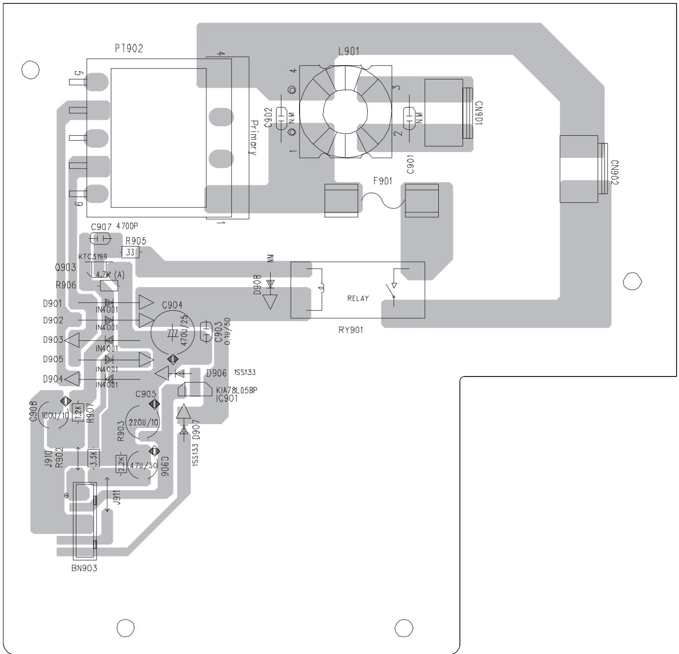
Power trans board
Block No. [0][3]
| △ Symbol No. | Part No. | Part Name | Description | Local |
| IC901 | 78L05 | IC | BI101851 | |
| Q903 | KTC3199GR | TRANSISTOR | BI2KTC3199GP000 | |
| D901 | 1N4001 | DIODE | BI31N4001M0006 | |
| D902 | 1N4001 | DIODE | BI31N4001M0006 | |
| D903 | 1N4001 | DIODE | BI31N4001M0006 | |
| D904 | 1N4001 | DIODE | BI31N4001M0006 | |
| D905 | 1N4001 | DIODE | BI31N4001M0006 | |
| C903 | BICH104500KM019 | CAPACITOR | 0.1uF 50V | |
| C904 | BICE477250MP015 | E CAPACITOR | 470uF 25V | |
| C905 | BICE227100MP015 | E CAPACITOR | 220uF | |
| C906 | BICE476160MP015 | E CAPACITOR | 47uF 16V | |
| C907 | BICH472500KM019 | CAPACITOR | 4700pF | |
| R902 | BIRC3320085M000 | C RESISTOR | 3.3KΩ 1/8W | |
| R903 | BIRC2220085M000 | C RESISTOR | 2.2KΩ 1/8W | |
| R905 | BIRC3300085M000 | C RESISTOR | 33Ω 1/8W | |
| R906 | BIRC4720085M000 | C RESISTOR | 4.7KΩ 1/8W | |
| R907 | BIRC1220085M000 | C RESISTOR | 1.2KΩ 1/8W | |
| △ L901 | BI2601102 | LINE FILTER | ||
| BN903 | BI12P60170V | WIRE | 6P | |
| CN901 | BI12S200691V | CONNECTOR | 2P | |
| CN902 | BI12S200691V | CONNECTOR | 2P | |
| △ PT902 | BI2110410070001 | POWER TRANS | 2598A | |
| △ RY901 | BI8RL00171V | RELAY | KTC3199GR | |
| XXXXX | BI251393G01V | POWER PCB | PT PCB |
CD board
Block No. [0][4]
| Symbol No. | Part No. | Part Name | Description | Local |
| IC701 | S1L9226 | IC | BI116431 | |
| IC703 | IP4001S | IC | BI118471 | |
| IC801 | S5L9279 | IC | BI116401 | |
| IC802 | K4S161622H-UC60 | IC | BI117401V | |
| IC803 | BH18FB1WG | IC | BI118171 | |
| IC871 | MN101C61G | IC | BI118121 | |
| IC872 | BR93L56RF | IC | BI118251 | |
| Q701 | KTA1266GR | TRANSISTOR | BI2KTA1266GP000 | |
| Q703 | KTA1273Y | TRANSISTOR | BI2KTA1273YP000 | |
| Q762 | DTC114TK | TRANSISTOR | BI2DTC114TKA011 | |
| Q871 | DTC114TK | TRANSISTOR | BI2DTC114TKA011 | |
| D762 | 1SS133 | FR DIODE | BI31SS133M000V7 | |
| C701 | BICC104500ZA043 | C CAPACITOR | 0.1uF 50V | |
| C702 | BICC104500ZA043 | C CAPACITOR | 0.1uF 50V | |
| C703 | BICC102500JA041 | C CAPACITOR | 1000pF 50V | |
| C704 | BICE476160MP111 | E CAPACITOR | 47uF 16V | |
| C705 | BICC102500JA041 | C CAPACITOR | 1000pF 50V | |
| C706 | BICC102500JA041 | C CAPACITOR | 1000pF 50V | |
| C707 | BICC103250KA042 | C CAPACITOR | 0.01uF 25V | |
| C708 | BICC473250KA042 | C CAPACITOR | 0.047uF 25V | |
| C709 | BICE227063MP111 | E CAPACITOR | 220uF 6.3V | |
| C710 | BICE107100MP111 | E CAPACITOR | 100uF 10V | |
| C711 | BICC040500CA041 | C CAPACITOR | 4pF 50V | |
| C712 | BICC100500DA041 | C CAPACITOR | 10pF 50V | |
| C713 | BICC682500KA042 | C CAPACITOR | 6800pF 50V | |
| C714 | BICC103250KA042 | C CAPACITOR | 0.01uF 25V | |
| C715 | BICE475500MP111 | E CAPACITOR | 4.7uF 50V | |
| C716 | BICC10450KA042 | C CAPACITOR | 0.1uF 50V | |
| C717 | BICC10450KA042 | C CAPACITOR | 0.1uF 50V |
| △ Symbol No. | Part No. | Part Name | Description | Local |
| C718 | BICC102500JA041 | C CAPACITOR | 1000pF 50V | |
| C719 | BICC10450KA042 | C CAPACITOR | 0.1uF 50V | |
| C720 | BICC333250KA042 | C CAPACITOR | 0.033uF 25V | |
| C721 | BICC474100KA042 | C CAPACITOR | 0.47uF 10V | |
| C722 | BICC474100KA042 | C CAPACITOR | 0.47uF 10V | |
| C723 | BICC332500KA042 | C CAPACITOR | 3300pF 50V | |
| C724 | BICC103250KA042 | C CAPACITOR | 0.01uF 25V | |
| C725 | BICC683160KA042 | C CAPACITOR | 0.068uF 16V | |
| C726 | BICE106100MP111 | E CAPACITOR | 10uF 10V | |
| C727 | BICC823160KA042 | C CAPACITOR | 0.082uF 16V | |
| C728 | BICC331500JA041 | C CAPACITOR | 330pF 50V | |
| C729 | BICC102500JA041 | C CAPACITOR | 1000pF 50V | |
| C730 | BICC222500KA042 | C CAPACITOR | 2200pF 50V | |
| C731 | BICC333250KA042 | C CAPACITOR | 0.033uF 25V | |
| C732 | BICC10450KA042 | C CAPACITOR | 0.1uF 50V | |
| C733 | BICC10450KA042 | C CAPACITOR | 0.1uF 50V | |
| C734 | BICC101500JA041 | C CAPACITOR | 100pF 50V | |
| C735 | BICC101500JA041 | C CAPACITOR | 100pF 50V | |
| C736 | BICC101500JA041 | C CAPACITOR | 100pF 50V | |
| C737 | BICC101500JA041 | C CAPACITOR | 100pF 50V | |
| C738 | BICC101500JA041 | C CAPACITOR | 100pF 50V | |
| C739 | BICC101500JA041 | C CAPACITOR | 100pF 50V | |
| C740 | BICC101500JA041 | C CAPACITOR | 100pF 50V | |
| C741 | BICC391500JA041 | C CAPACITOR | 390pF 50V | |
| C742 | BICC391500JA041 | C CAPACITOR | 390pF 50V | |
| C743 | BICC391500JA041 | C CAPACITOR | 390pF 50V | |
| C744 | BICC391500JA041 | C CAPACITOR | 390pF 50V | |
| C755 | BICC102500JA041 | C CAPACITOR | 1000pF 50V | |
| C756 | BICC102500JA041 | C CAPACITOR | 1000pF 50V | |
| C761 | BICE477100MP015 | E CAPACITOR | 470uF 10V | |
| C762 | BICC104500ZA043 | C CAPACITOR | 0.1uF 50V | |
| C763 | BICE107100MP111 | E CAPACITOR | 100uF 10V | |
| C803 | BICE107100MP111 | E CAPACITOR | 100uF 10V | |
| C804 | BICC104500ZA043 | C CAPACITOR | 0.1uF 50V | |
| C805 | BICC270500JA041 | C CAPACITOR | 27pF 50V | |
| C806 | BICC270500JA041 | C CAPACITOR | 27pF 50V | |
| C807 | BICC104500ZA043 | C CAPACITOR | 0.1uF 50V | |
| C808 | BICE107100MP111 | E CAPACITOR | 100uF 10V | |
| C809 | BICC10450KA042 | C CAPACITOR | 0.1uF 50V | |
| C810 | BICC122500KA042 | C CAPACITOR | 1200pF 50V | |
| C811 | BICC122500KA042 | C CAPACITOR | 1200pF 50V | |
| C812 | BICC122500KA042 | C CAPACITOR | 1200pF 50V | |
| C813 | BICC104500ZA043 | C CAPACITOR | 0.1uF 50V | |
| C814 | BICE107100MP111 | E CAPACITOR | 100uF 10V | |
| C815 | BICE107100MP111 | E CAPACITOR | 100uF 10V | |
| C816 | BICC104500ZA043 | C CAPACITOR | 0.1uF 50V | |
| C817 | BICC104500ZA043 | C CAPACITOR | 0.1uF 50V | |
| C818 | BICC104500ZA043 | C CAPACITOR | 0.1uF 50V | |
| C819 | BICC104500ZA043 | C CAPACITOR | 0.1uF 50V | |
| C820 | BICC104500ZA043 | C CAPACITOR | 0.1uF 50V | |
| C821 | BICC104500ZA043 | C CAPACITOR | 0.1uF 50V | |
| C822 | BICC104500ZA043 | C CAPACITOR | 0.1uF 50V | |
| C823 | BICC104500ZA043 | C CAPACITOR | 0.1uF 50V | |
| C825 | BICC103250KA042 | C CAPACITOR | 0.01uF 25V | |
| C826 | BICE106100MP111 | E CAPACITOR | 10uF 10V | |
| C827 | BICE106100MP111 | E CAPACITOR | 10uF 10V | |
| C835 | BICC100500DA041 | C CAPACITOR | 10pF 50V | |
| C841 | BICC102500KA042 | C CAPACITOR | 1000pF 50V | |
| C842 | BICC330500JA041 | C CAPACITOR | 33pF 50V | |
| C843 | BICC330500JA041 | C CAPACITOR | 33pF 50V | |
| C844 | BICC330500JA041 | C CAPACITOR | 33pF 50V | |
| C871 | BICC103250KA042 | C CAPACITOR | 0.01uF 25V | |
| C872 | BICC104500ZA043 | C CAPACITOR | 0.1uF 50V | |
| C873 | BICC150500JA041 | C CAPACITOR | 15pF 50V | |
| C874 | BICC101500JA041 | C CAPACITOR | 100pF 50V | |
| C875 | BICC330500JA041 | C CAPACITOR | 33pF 50V | |
| C876 | BICC470500JA041 | C CAPACITOR | 47pF 50V | |
| C877 | BICC470500JA041 | C CAPACITOR | 47pF 50V | |
| C878 | BICC470500JA041 | C CAPACITOR | 47pF 50V | |
| C880 | BICC470500JA041 | C CAPACITOR | 47pF 50V | |
| C881 | BICC470500JA041 | C CAPACITOR | 47pF 50V | |
| C882 | BICC10450KA042 | C CAPACITOR | 0.1uF 50V | |
| C883 | BICC104500ZA043 | C CAPACITOR | 0.1uF 50V | |
| R701 | BIRC0820105A005 | C RESISTOR | 8.2Ω 1/10W | |
| R702 | BIRC1840105A005 | C RESISTOR | 180KΩ 1/10W | |
| R703 | BIRC3930105A005 | C RESISTOR | 39KΩ 1/10W | |
| R704 | BIRC3930105A005 | C RESISTOR | 39KΩ 1/10W | |
| Symbol No. | Part No. | Part Name | Description | Local |
| R705 | BIRC3930105A005 | C RESISTOR | 39KΩ 1/10W | |
| R706 | BIRC3930105A005 | C RESISTOR | 39KΩ 1/10W | |
| R707 | BIRC1840105A005 | C RESISTOR | 180KΩ 1/10W | |
| R708 | BIRC4700105A005 | C RESISTOR | 47Ω 1/10W | |
| R709 | BIRC4720105A005 | C RESISTOR | 4.7KΩ 1/10W | |
| R710 | BIRC1010105A005 | C RESISTOR | 100Ω 1/10W | |
| R711 | BIRC5620105A005 | C RESISTOR | 5.6KΩ 1/10W | |
| R714 | BIRC1030105A005 | C RESISTOR | 10KΩ 1/10W | |
| R715 | BIRC1830105A005 | C RESISTOR | 18KΩ 1/10W | |
| R716 | BIRC2230105A005 | C RESISTOR | 22KΩ 1/10W | |
| R717 | BIRC1050105A005 | C RESISTOR | 1MΩ 1/10W | |
| R718 | BIRC1030105A005 | C RESISTOR | 10KΩ 1/10W | |
| R719 | BIRC5620105A005 | C RESISTOR | 5.6KΩ 1/10W | |
| R720 | BIRC1020105A005 | C RESISTOR | 1KΩ 1/10W | |
| R721 | BIRC1030105A005 | C RESISTOR | 10KΩ 1/10W | |
| R722 | BIRC1030105A005 | C RESISTOR | 10KΩ 1/10W | |
| R723 | BIRC8230105A005 | C RESISTOR | 82KΩ 1/10W | |
| R724 | BIRC8230105A005 | C RESISTOR | 82KΩ 1/10W | |
| R725 | BIRC1530105A005 | C RESISTOR | 15KΩ 1/10W | |
| R726 | BIRC4730105A005 | C RESISTOR | 47KΩ 1/10W | |
| R727 | BIRC1240105A005 | C RESISTOR | 120KΩ 1/10W | |
| R728 | BIRC2730105A005 | C RESISTOR | 27KΩ 1/10W | |
| R729 | BIRC1540105A005 | C RESISTOR | 150KΩ 1/10W | |
| R730 | BIRC1240105A005 | C RESISTOR | 120KΩ 1/10W | |
| R731 | BIRC1040105A005 | C RESISTOR | 100KΩ 1/10W | |
| R732 | BIRC4730105A005 | C RESISTOR | 47KΩ 1/10W | |
| R746 | BIRC1010085M000 | C RESISTOR | 100Ω 1/8W | |
| R747 | BIRC1010085M000 | C RESISTOR | 100Ω 1/8W | |
| R756 | BIRC1030105A005 | C RESISTOR | 10KΩ 1/10W | |
| R757 | BIRC1830085M000 | C RESISTOR | 18KΩ 1/8W | |
| R763 | BIRC1220105A005 | C RESISTOR | 1.2KΩ 1/10W | |
| R764 | BIRC1030105A005 | C RESISTOR | 10KΩ 1/10W | |
| R765 | BIRC4710105A005 | C RESISTOR | 470Ω 1/10W | |
| R771 | BIRC1020105A005 | C RESISTOR | 1KΩ 1/10W | |
| R802 | BIRC1020085N000 | C RESISTOR | 1KΩ 1/8W | |
| R803 | BIRC1020085N000 | C RESISTOR | 1KΩ 1/8W | |
| R804 | BIRC3310105A005 | C RESISTOR | 330Ω 1/10W | |
| R805 | BIRC1050105A005 | C RESISTOR | 1MΩ 1/10W | |
| R806 | BIRC1020085M000 | C RESISTOR | 1KΩ 1/8W | |
| R807 | BIRC3310105A005 | C RESISTOR | 330Ω 1/10W | |
| R808 | BIRC1010085M000 | C RESISTOR | 100Ω 1/8W | |
| R809 | BIRC1210085M000 | C RESISTOR | 120Ω 1/8W | |
| R810 | BIRC1210105A005 | C RESISTOR | 120Ω 1/10W | |
| R811 | BIRC1010105A005 | C RESISTOR | 100Ω 1/10W | |
| R812 | BIRC1230105A005 | C RESISTOR | 12KΩ 1/10W | |
| R813 | BIRC1230105A005 | C RESISTOR | 12KΩ 1/10W | |
| R814 | BIRC1010105A005 | C RESISTOR | 100Ω 1/10W | |
| R836 | BIRC1040105A005 | C RESISTOR | 100KΩ 1/10W | |
| R837 | BIRC1040105A005 | C RESISTOR | 100KΩ 1/10W | |
| R841 | BIRC1020085M000 | C RESISTOR | 1KΩ 1/8W | |
| R842 | BIRC1020085M000 | C RESISTOR | 1KΩ 1/8W | |
| R843 | BIRC1020085M000 | C RESISTOR | 1KΩ 1/8W | |
| R844 | BIRC1020085M000 | C RESISTOR | 1KΩ 1/8W | |
| R845 | BIRC1020085M000 | C RESISTOR | 1KΩ 1/8W | |
| R846 | BIRC1020085M000 | C RESISTOR | 1KΩ 1/8W | |
| R847 | BIRC1020085M000 | C RESISTOR | 1KΩ 1/8W | |
| R848 | BIRC1020085M000 | C RESISTOR | 1KΩ 1/8W | |
| R849 | BIRC1020085M000 | C RESISTOR | 1KΩ 1/8W | |
| R850 | BIRC1020085M000 | C RESISTOR | 1KΩ 1/8W | |
| R851 | BIRC1020085M000 | C RESISTOR | 1KΩ 1/8W | |
| R852 | BIRC1020085M000 | C RESISTOR | 1KΩ 1/8W | |
| R853 | BIRC1020085M000 | C RESISTOR | 1KΩ 1/8W | |
| R854 | BIRC1020085M000 | C RESISTOR | 1KΩ 1/8W | |
| R871 | BIRC1020105A005 | C RESISTOR | 1KΩ 1/10W | |
| R876 | BIRC1210085M000 | C RESISTOR | 120Ω 1/8W | |
| R877 | BIRC1210085M000 | C RESISTOR | 120Ω 1/8W | |
| R878 | BIRC1210085M000 | C RESISTOR | 120Ω 1/8W | |
| R879 | BIRC1210085M000 | C RESISTOR | 120Ω 1/8W | |
| R880 | BIRC1210085M000 | C RESISTOR | 120Ω 1/8W | |
| R881 | BIRC1210085M000 | C RESISTOR | 120Ω 1/8W | |
| R882 | BIRC1030105A005 | C RESISTOR | 10KΩ 1/10W | |
| R883 | BIRC1030105A005 | C RESISTOR | 10KΩ 1/10W | |
| R884 | BIRC1020085M000 | C RESISTOR | 1KΩ 1/8W | |
| R885 | BIRC1020085M000 | C RESISTOR | 1KΩ 1/8W | |
| R886 | BIRC1020105A005 | C RESISTOR | 1KΩ 1/10W | |
| R887 | BIRC1020105A005 | C RESISTOR | 1KΩ 1/10W | |
| R888 | BIRC1020105A005 | C RESISTOR | 1KΩ 1/10W | |
| R889 | BIRC1020105A005 | C RESISTOR | 1KΩ 1/10W |
| Symbol No. | Part No. | Part Name | Description | Local |
| R890 | BIRC1020085N000 | C RESISTOR | 1K 1/8W | |
| R891 | BIRC1020105A005 | C RESISTOR | 1K 1/10W | |
| R892 | BIRC1020105A005 | C RESISTOR | 1K 1/10W | |
| R893 | BIRC1020105A005 | C RESISTOR | 1K 1/10W | |
| R894 | BIRC1020105A005 | C RESISTOR | 1K 1/10W | |
| R895 | BIRC1030105A005 | C RESISTOR | 10K 1/10W | |
| R896 | BIRC1030105A005 | C RESISTOR | 10K 1/10W | |
| L710 | BI26100000KM002 | COIL | 10uH | |
| L761 | BI18A843556N000 | FILTER BEAD | 843556 | |
| L801 | BI26100000KN000 | COIL | 10uH | |
| L802 | BI26100000KN000 | COIL | 10uH | |
| L803 | BI26100000KM002 | COIL | 10uH | |
| L804 | BI26100000KM002 | COIL | 10uH | |
| L805 | BI26100000KM002 | COIL | 10uH | |
| L806 | BI26100000KN000 | COIL | 10uH | |
| L808 | BI18A843556N000 | FILTER BEAD | 843556 | |
| L809 | BI18A916121A005 | FERITTE BEAD | 120ohm | |
| L822 | BI18A843556N000 | FILTER BEAD | 843556 | |
| L871 | BI26100000KM002 | COIL | 10uH | |
| CN701 | BI12S160043V | SOCKET | 16PIN H | |
| CN702 | BI12P60170V | WIRE | 6P P=2.0mm | |
| CN801 | BI12S280005U | SOCKET | 28P | |
| CN802 | BI12S120038 | SOCKET | 12P | |
| CN871 | BI12S150027V | SOCKET | 15PIN H | |
| CN872 | BI12S200161 | SOCKET CONNECTOR | 2 P | |
| CN873 | BI12S30039 | SOCKET | 3P | |
| JR701 | BIRC0000105A005 | C RESISTOR | 0 1/10W | |
| JR702 | BIRC0000105A005 | C RESISTOR | 0 1/10W | |
| JR704 | BIRC0000105A005 | C RESISTOR | 0 1/10W | |
| JR706 | BIRC0000105A005 | C RESISTOR | 0 1/10W | |
| JR707 | BIRC0000105A005 | C RESISTOR | 0 1/10W | |
| JR708 | BIRC0000105A005 | C RESISTOR | 0 1/10W | |
| JR801 | BIRC0000105A005 | C RESISTOR | 0 1/10W | |
| JR802 | BIRC0000105A005 | C RESISTOR | 0 1/10W | |
| JR803 | BIRC0000085A003 | C RESISTOR | 0 1/10W | |
| JR804 | BIRC0000085A003 | C RESISTOR | 0 1/10W | |
| JW801 | BI18A843556N000 | FILTER BEAD | 843556 | |
| X801 | BI2100796 | CRYSTAL | 16.9344MHZ | |
| X871 | BI29ZTA800P015U | CRYSTAL | 8MHz | |
| XXXXX | BI251396G01V | PCB | CD PCB | |
| XXXXX | BI301635010101 | CUSH |
Amp. board
Block No. [0][5]
| Symbol No. | Part No. | Part Name | Description | Local |
| IC102 | NJM79L09 | IC | BI118381 | |
| IC103 | KIA7809AP | IC | BI111971 | |
| IC104 | KIA7808AP | IC | BI110891 | |
| IC105 | STK403-090 | IC | BI118401 | |
| Q101 | KTB1366Y | TRANSISTOR | BI2KTB1366Y8V | |
| Q102 | 2SC3052 | TRANSISTOR | BI2SC3052FA013V | |
| Q121 | KTC3198GR | TRANSISTOR | BI2KTC3198GP000 | |
| Q131 | 2SC3052 | TRANSISTOR | BI2SC3052FA013V | |
| Q132 | KTA1273Y | TRANSISTOR | BI2KTA1273YP000 | |
| Q133 | KTA1273Y | TRANSISTOR | BI2KTA1273YP000 | |
| Q134 | 2SC3052 | TRANSISTOR | BI2SC3052FA013V | |
| Q151 | 2SC3052 | TRANSISTOR | BI2SC3052FA013V | |
| Q153 | 2SC3052 | TRANSISTOR | BI2SC3052FA013V | |
| Q154 | 2SC3052 | TRANSISTOR | BI2SC3052FA013V | |
| Q155 | 2SC3052 | TRANSISTOR | BI2SC3052FA013V | |
| Q157 | 2SC3052 | TRANSISTOR | BI2SC3052FA013V | |
| Q171 | 2SC3052 | TRANSISTOR | BI2SC3052FA013V | |
| Q172 | 2SC3052 | TRANSISTOR | BI2SC3052FA013V | |
| Q201 | DTC323TK | TRANSISTOR | BI2DTC323TKA011 | |
| Q202 | DTC323TK | TRANSISTOR | BI2DTC323TKA011 | |
| Q203 | DTC114TK | TRANSISTOR | BI2DTC114TKA011 |
| △ Symbol No. | Part No. | Part Name | Description | Local | △ Symbol No. | Part No. | Part Name | Description | Local |
| Q204 | DTA114YK | TRANSISTOR | BI2DTA114YKA011 | C202 | BICE476250MP015 | E CAPACITOR | 47uF 25V | ||
| Q241 | 2SA1235F | TRANSISTOR | BI2SA1235FA012V | C203 | BICE105500MP015 | E CAPACITOR | 1uF 50V | ||
| Q242 | 2SA1235F | TRANSISTOR | BI2SA1235FA012V | C204 | BICE105500MP015 | E CAPACITOR | 1uF 50V | ||
| Q243 | KTC3199GR | TRANSISTOR | BI2KTC3199GP00 | C205 | BICC471500KA042 | C CAPACITOR | 470pF 50V | ||
| 0 | C206 | BICC471500KA042 | C CAPACITOR | 470pF 50V | |||||
| Q244 | DTC114YK | TRANSISTOR | BI2DTC114YKA011 | C207 | BICC221500JA041 | C CAPACITOR | 220pF 50V | ||
| Q291 | DTC323TK | TRANSISTOR | BI2DTC323TKA01 | C208 | BICC221500JA041 | C CAPACITOR | 220pF 50V | ||
| 1 | C213 | BICE107500MP015 | E CAPACITOR | 100uF 50V | |||||
| Q292 | DTC323TK | TRANSISTOR | BI2DTC323TKA01 | C214 | BICE107500MP015 | E CAPACITOR | 100uF 50V | ||
| 1 | C215 | BICE476500MP015 | CAPACITOR | 47uF 50V | |||||
| Q293 | DTC114TK | TRANSISTOR | BI2DTC114TKA011 | C216 | BICE476500MP015 | CAPACITOR | 47uF 50V | ||
| Q294 | DTA114YK | TRANSISTOR | BI2DTA114YKA011 | C237 | BICC104500KA042 | C CAPACITOR | 0.1uF 50V | ||
| C238 | BICC104500KA042 | C CAPACITOR | 0.1uF 50V | ||||||
| D101 | 1SS133 | FR DIODE | BI31SS133M000V | C239 | BICC104500KA042 | C CAPACITOR | 0.1uF 50V | ||
| 7 | C240 | BICC104500KA042 | C CAPACITOR | 0.1uF 50V | |||||
| D102 | 1SS133 | FR DIODE | BI31SS133M000V | C241 | BICE106500MP015 | E CAPACITOR | 10uF 50V | ||
| 7 | C242 | BICE105500MP015 | E CAPACITOR | 1uF 50V | |||||
| D104 | 1SS133 | FR DIODE | BI31SS133M000V | C243 | BICC153500KA042 | C CAPACITOR | 0.015uF 50V | ||
| 7 | C244 | BICC153500KA042 | C CAPACITOR | 0.015uF 50V | |||||
| D105 | 1SS133 | FR DIODE | BI31SS133M000V | ||||||
| 7 | |||||||||
| D131 | MC2838 | C DIODE | BI3MC2838A002V | R101 | BIRF0220045N000 | F RESISTOR | 2.2Ω 1/4W | ||
| H | R104 | BIRC6820105A005 | C RESISTOR | 6.8KΩ 1/10W | |||||
| D133 | 1SS133 | FR DIODE | BI31SS133M000V | R105 | BIRC3320105A005 | C RESISTOR | 3.3KΩ 1/10W | ||
| 7 | R107 | BIRC2210105A005 | C RESISTOR | 220Ω 1/10W | |||||
| D153 | 1SS133 | FR DIODE | BI31SS133M000V | R108 | BIRC2210105A005 | C RESISTOR | 220Ω 1/10W | ||
| 7 | R109 | BIRC2210105A005 | C RESISTOR | 220Ω 1/10W | |||||
| D154 | 1SS133 | FR DIODE | BI31SS133M000V | R110 | BIRC2210105A005 | C RESISTOR | 220Ω 1/10W | ||
| 7 | R111 | BIRC1020105A005 | C RESISTOR | 1KΩ 1/10W | |||||
| D157 | 1SS133 | FR DIODE | BI31SS133M000V | R121 | BIRC2210105A005 | C RESISTOR | 220Ω 1/10W | ||
| 7 | R131 | BIRC4730105A005 | C RESISTOR | 47KΩ 1/10W | |||||
| D171 | RS603M | DIODE | BI3RS603M1 | R132 | BIRC4730105A005 | C RESISTOR | 47KΩ 1/10W | ||
| D172 | RS202 | DIODE | BI3RS2021 | R134 | BIRC2240105A005 | C RESISTOR | 220KΩ 1/10W | ||
| D173 | 1SS133 | FR DIODE | BI31SS133M000V | R135 | BIRC4730105A005 | C RESISTOR | 47KΩ 1/10W | ||
| 7 | R136 | BIRC5600105A005 | C RESISTOR | 56Ω 1/10W | |||||
| D201 | 1SS133 | FR DIODE | BI31SS133M000V | R137 | BIRC1030105A005 | C RESISTOR | 10KΩ 1/10W | ||
| 7 | R139 | BIRC1030105A005 | C RESISTOR | 10KΩ 1/10W | |||||
| D231 | 1SS355 | DIODE | BI31SS355A0077 | R140 | BIRC5600045M000 | C RESISTOR | 56Ω 1/4W | ||
| D232 | 1SS355 | DIODE | BI31SS355A0077 | R141 | BIRC1510045M000 | C RESISTOR | 150Ω 1/4W | ||
| D233 | 1SS133 | FR DIODE | BI31SS133M000V | R142 | BIRC5620105A005 | C RESISTOR | 5.6KΩ 1/10W | ||
| 7 | R143 | BIRC1030105A005 | C RESISTOR | 10KΩ 1/10W | |||||
| D234 | 1SS355 | DIODE | BI31SS355A0077 | R144 | BIRC5620105A005 | C RESISTOR | 5.6KΩ 1/10W | ||
| D235 | 1SS355 | DIODE | BI31SS355A0077 | R151 | BIRC1830105A005 | C RESISTOR | 18KΩ 1/10W | ||
| D236 | 1SS355 | DIODE | BI31SS355A0077 | R152 | BIRC6840105A005 | C RESISTOR | 680KΩ 1/10W | ||
| C101 | BICM103101KP015 | M CAPACITOR | 0.01uF 100V | R153 | BIRC1030085M000 | C RESISTOR | 10KΩ 1/8W | ||
| C102 | BICM103101KP015 | M CAPACITOR | 0.01uF 100V | R155 | BIRC4700105A005 | C RESISTOR | 47Ω 1/10W | ||
| C103 | BICE33856M1 | E CAPACITOR | 3300uF 56V | R156 | BIRC1040105A005 | C RESISTOR | 100KΩ 1/10W | ||
| C104 | BICE33856M1 | E CAPACITOR | 3300uF 56V | R157 | BIRC1030105A005 | C RESISTOR | 10KΩ 1/10W | ||
| C105 | BICE47825M61 | E CAPACITOR | 4700uF 25V | R158 | BIRC3910105A005 | C RESISTOR | 390Ω 1/10W | ||
| C106 | BICE108250MP015 | E CAPACITOR | 1000uF 25V | R174 | BIRC2230105A005 | C RESISTOR | 22KΩ 1/10W | ||
| C107 | BICC103500KA042 | C CAPACITOR | 0.01uF 50V | R175 | BIRC2230085M000 | C RESISTOR | 22KΩ 1/8W | ||
| C108 | BICC103500KA042 | C CAPACITOR | 0.01uF 50V | R176 | BIRC2220105A005 | C RESISTOR | 2.2KΩ 1/10W | ||
| C109 | BICE108160MP015 | E CAPACITOR | 1000uF 16V | R201 | BIRC3920105A005 | C RESISTOR | 3.9KΩ 1/10W | ||
| C110 | BICE477250MP015 | E CAPACITOR | 470uF25V | R203 | BIRC1030105A005 | C RESISTOR | 10KΩ 1/10W | ||
| C113 | BICE108160MP015 | E CAPACITOR | 1000uF 16V | R204 | BIRC1030105A005 | C RESISTOR | 10KΩ 1/10W | ||
| C114 | BICC104500ZA043 | C CAPACITOR | 0.1uF 50V | R205 | BIRC2220105A005 | C RESISTOR | 2.2KΩ 1/10W | ||
| C115 | BICE108160MP015 | E CAPACITOR | 1000uF 16V | R206 | BIRC2220105A005 | C RESISTOR | 2.2KΩ 1/10W | ||
| C116 | BICC104500ZA043 | C CAPACITOR | 0.1uF 50V | R207 | BIRC2730105A005 | C RESISTOR | 27KΩ 1/10W | ||
| C117 | BICE107160MP015 | E CAPACITOR | 100uF 16V | R208 | BIRC2730105A005 | C RESISTOR | 27KΩ 1/10W | ||
| C118 | BICC104500ZA043 | C CAPACITOR | 0.1uF 50V | R209 | BIRC2020105A005 | C RESISTOR | 2KΩ 1/10W | ||
| C121 | BICE227100MP015 | E CAPACITOR | 220uF 10V | R210 | BIRC2020105A005 | C RESISTOR | 2KΩ 1/10W | ||
| C122 | BICC104500ZA043 | C CAPACITOR | 0.1uF 50V | R211 | BIRF1010025N000 | F RESISTOR | 100Ω 1/2W | ||
| C123 | BICE227100MP015 | E CAPACITOR | 220uF 10V | R212 | BIRF1010025N000 | F RESISTOR | 100Ω 1/2W | ||
| C124 | BICC104500ZA043 | C CAPACITOR | 0.1uF 50V | R215 | BIRC5630105A005 | C RESISTOR | 56KΩ 1/10W | ||
| C131 | BICE105500MP111 | E CAPACITOR | 1uF 50V | R216 | BIRC5630105A005 | C RESISTOR | 56KΩ 1/10W | ||
| C132 | BICE106500MP115 | E CAPACITOR | 1uF 50V | R217 | BIRM0022N25N000 | C RESISTOR | 0.22Ω 2W | ||
| C134 | BICE227160MP111 | E CAPACITOR | 220uF 16V | R218 | BIRM0022N25N000 | C RESISTOR | 0.22Ω 2W | ||
| C151 | BICC222500KA042 | C CAPACITOR | 220oPf 50V | R259 | BIRC1020085N000 | C RESISTOR | 1KΩ 1/8W | ||
| C153 | BICE105500MP015 | E CAPACITOR | 1uF 50V | R260 | BIRC1020105A005 | C RESISTOR | 1KΩ 1/10W | ||
| C154 | BICE226160MP015 | E CAPACITOR | 22uF 16V | R261 | BIRC1530105A005 | C RESISTOR | 15KΩ 1/10W | ||
| C155 | BICE475500MP015 | E CAPACITOR | 4.7uF 50V | R262 | BIRC1530105A005 | C RESISTOR | 15KΩ 1/10W | ||
| C157 | BICE107160MP015 | E CAPACITOR | 100uF 16V | R263 | BIRC1020105A005 | C RESISTOR | 1KΩ 1/10W | ||
| C171 | BICC103500KA042 | C CAPACITOR | 0.01uF 50V | R264 | BIRC1020105A005 | C RESISTOR | 1KΩ 1/10W | ||
| C172 | BICC103500KA042 | C CAPACITOR | 0.01uF 50V | R269 | BIRC1540105A005 | C RESISTOR | 150KΩ 1/10W | ||
| C173 | BICM223101KP015 | M CAPACITOR | 0.022uF 100V | R270 | BIRC1540085M000 | C RESISTOR | 150KΩ 1/8W | ||
| C174 | BICE106500MP015 | E CAPACITOR | 10uF 50V | R275 | BIRC220085M000 | C RESISTOR | 22Ω 1/8W | ||
| C175 | BICC103500KA042 | C CAPACITOR | 0.01uF 50V | R276 | BIRC220085M000 | C RESISTOR | 22Ω 1/8W | ||
| C176 | BICC103500KA042 | C CAPACITOR | 0.01uF 50V | R277 | BIRC220085M000 | C RESISTOR | 22Ω 1/8W | ||
| C177 | BICC223500KA042 | C CAPACITOR | 0.022uF 50V | R278 | BIRC220085M000 | C RESISTOR | 22Ω 1/8W |
| Symbol No. | Part No. | Part Name | Description | Local |
| R279 | BIRC2200085A002 | C RESISTOR | 22 1/8W | |
| R280 | BIRC2200085A002 | C RESISTOR | 22 1/8W | |
| R281 | BIRC2200085A002 | C RESISTOR | 22 1/8W | |
| R282 | BIRC2200085A002 | C RESISTOR | 22 1/8W | |
| R283 | BIRC1030105A005 | C RESISTOR | 10K 1/10W | |
| R284 | BIRC1030105A005 | C RESISTOR | 10K 1/10W | |
| R285 | BIRC4710105A005 | C RESISTOR | 470 1/10W | |
| R286 | BIRC4740105A005 | C RESISTOR | 470K 1/10W | |
| R287 | BIRC1000085M000 | C RESISTOR | 10 1/8W | |
| R289 | BIRC2220105A005 | C RESISTOR | 2.2K 1/10W | |
| R290 | BIRC1030105A005 | C RESISTOR | 10K 1/10W | |
| R291 | BIRC6810025N000 | C RESISTOR | 680 1/2W | |
| R292 | BIRC6810025N000 | C RESISTOR | 680 1/2W | |
| R293 | BIRC2710105A005 | C RESISTOR | 270 1/10W | |
| R294 | BIRC2710105A005 | C RESISTOR | 270 1/10W | |
| R295 | BIRC2220105A005 | C RESISTOR | 2.2K 1/10W | |
| R296 | BIRC2220105A005 | C RESISTOR | 2.2K 1/10W | |
| R297 | BIRC3920105A005 | C RESISTOR | 3.9K 1/10W | |
| L101 | BI18A843556N000 | FILTER BEAD | 843556 | |
| L201 | BI2600702V | CHOCK COIL | 1.0uH | |
| L202 | BI2600702V | CHOCK COIL | 1.0uH | |
| CN101 | BI12S60119V | SOCKET | 6P | |
| CN102 | BI12S600961 | CONNECTOR | 6P | |
| CN105 | BI12S20057V | SOCKET | 2P | |
| CN157 | BI12S200161V | SOCKET | 2P | |
| CN201 | BI12S150028V | SOCKET | 15P | |
| CN202 | BI12S80058V | SOCKET | 8 P | |
| CN204 | BI12S40047V | SOCKET | 4P | |
| JR101 | BIRC0000085A003 | C RESISTOR | 0 1/8W | |
| JR102 | BIRC0000085A003 | C RESISTOR | 0 1/8W | |
| JR103 | BIRC0000085A003 | C RESISTOR | 0 1/8W | |
| JR104 | BIRC0000085A003 | C RESISTOR | 0 1/8W | |
| JR105 | BIRC0000085A003 | C RESISTOR | 0 1/8W | |
| JR106 | BIRC0000085A003 | C RESISTOR | 0 1/8W | |
| JR107 | BIRC0000085A003 | C RESISTOR | 0 1/8W | |
| P103 | BI11A050M0Y | BLACK WIRE | ||
| RY201 | BI8RL00191V | RELAY | DC 12V | |
| SP201 | BI23F0741V | TERMINAL SP | 4P | |
| XXXXX | BI251394G01V | AMP PCB | AMP PCB | |
| XXXXX | BI202903010101 | HEAT SINK | ||
| XXXXX | BIRT000617B3 | SCREW | 3 × L10mm(x3) | |
| XXXXX | BI202672010101 | HEAT SINK | IC104 | |
| XXXXX | BIBT0006091 | SCREW | (x2) | |
| XXXXX | BIBT000604S3 | SCREW | ||
| XXXXX | BI12P20205V | CONNECTOR ASSY | 2P P=2.0mm | |
| XXXXX | BIRT103THMSP015 | SCREW | 10K | |
| XXXXX | BIRT000611B3 | SCREW | (x2) | |
| ZD101 | UZ12BSC | Z DIODE | BI3UZ12BSCM000 V | |
| ZD121 | MTZ J 3.3B | Z DIODE | BI3MTZJ33BM000 V | |
| ZD157 | UZ5.6BSB | Z DIODE | BI3UZ56BSBM000 V |
Wiring
Block No. [0][6]
| △ Symbol No. | Part No. | Part Name | Description | Local |
| XXXXX | BI1206561V | FFC CABLE | 16P 1.0 L=95mm | |
| XXXXX | BI1206821V | FFC CABLE | 12P 1.25 L=50mm | |
| XXXXX | BI1206831V | FFC CABLE | 16P 1.25 L=200mm | |
| XXXXX | BI1206841V | FFC CABLE | 28P 1.25 L=180mm | |
| XXXXX | BI1206851V | FFC CABLE | 12P 1.25 L=160mm |
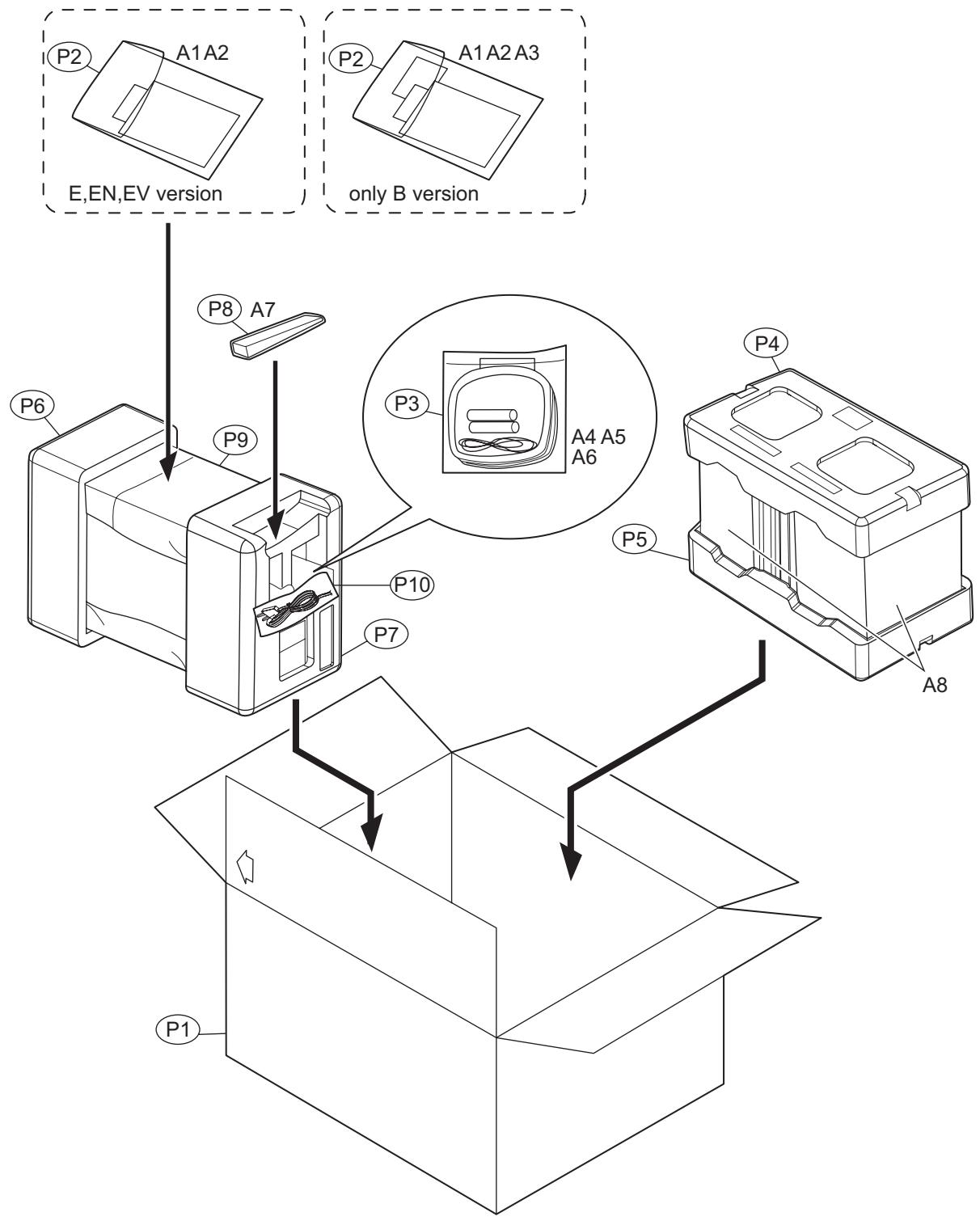
Packing materials and accessories parts list
Block No. M 3 M M
No additional / supplemental order of WARRANTY CARDs are available.
text_image
P2 A1 A2 E,EN,EV version P8 A7 P9 P10 P7 P3 A4 A5 A6 P4 A8 P1Packing and Accessories
Block No. [M][3][M][M]
| △ Symbol No. | Part No. | Part Name | Description | Local | |
| A 1 | BI440001532000 | INST BOOK | ENG LVT1358-001A | B | |
| A 1 | BI440001531000 | INST BOOK | GER FRE DUT LVT1358-002A | E | |
| A 1 | BI440001540000 | INST BOOK | SWE FIN DAN GER FRE SPA ITA LVT1358-003A EN | ||
| A 1 | BI440001544000 | INST BOOK | POL HUN CZE LVT1358-004A | EV | |
| A 2 | ---- | WARRANTY CARD | BT-54026-1 | ||
| A 3 | BI400083291001 | REGISTRATION CARD | B | ||
| A 4 | ---- | BATTERY | (x2) | ||
| A 5 | BIAN01281V | AM LOOP ANT | |||
| A 6 | BIAN01022V | ANT WIRE FM | |||
| A 7 | BI643UXS59020 | REMOTE CONTROL | |||
| A 8 | BI644UXS59202S | SPEAKER SYSTEM | (x2) | ||
| P 1 | BI430001843000 | CARTON | |||
| P 2 | BI470011031001W | POLY BAG | I/B | ||
| P 3 | BI470011057001W | POLY BAG | ANT LOOP | ||
| P 4 | BI450012012000 | TOP CUSHION | Speaker Box | ||
| P 5 | BI450012013000 | BOTTOM CUSHION | Speaker Box | ||
| P 6 | BI450012031000W | FRONT CUSHION | UNIT | ||
| P 7 | BI450012030000W | REAR CUSHION | UNIT | ||
| P 8 | BI4005355 | POLY BAG | for Remote control | ||
| P 9 | BI450032001000W | PROTECT SHEET | UNIT | ||
| P 10 | BI470011067001W | POLY BAG | For AC Cord | ||
JVC
SCHEMATIC DIAGRAMS
MICRO COMPONENT SYSTEM
UX-S59
CD-ROM No.SML200507
Area suffix
B U.K.
E ---- Continental Europe
EN ---- Northern Europe
EV ---- Eastern Europe
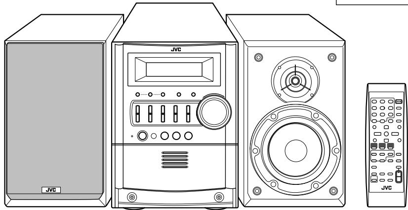
natural_image
Line drawing of a JVC audio amplifier with three speakers and control panel (no text or symbols)


Lead free solder used in the board (material : Sn-Ag-Cu, melting point : 219 Centigrade)
Contents
Block diagram 2-1
Standard schematic diagrams 2-2
Printed circuit boards 2-6 to 11
In regard with component parts appearing on the silk-screen printed side (parts side) of the PWB diagrams, the parts that are printed over with black such as the resistor (—), diode (■) and ICP (●) or identified by the "△" mark nearby are critical for safety.
Block diagram
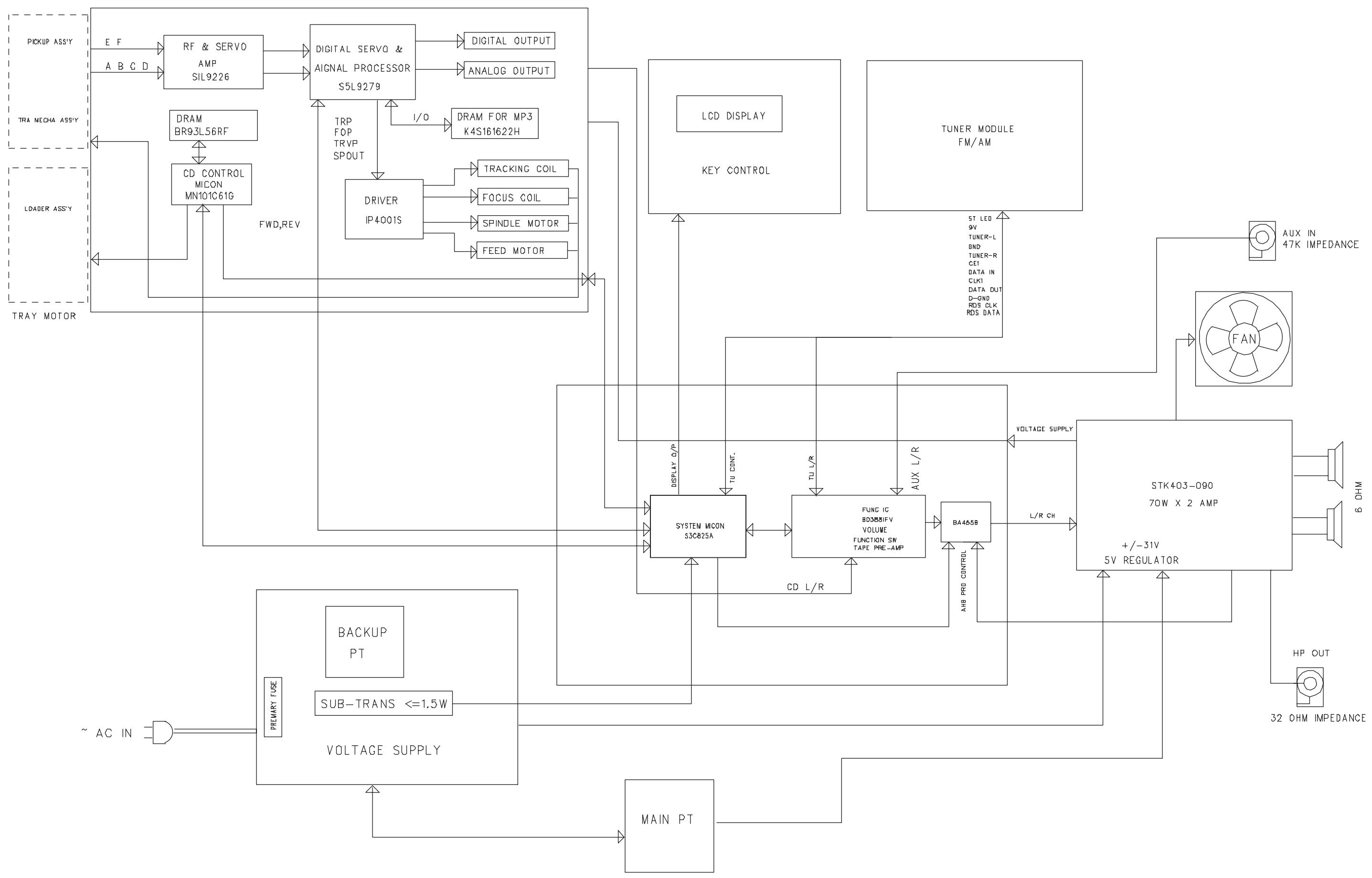
flowchart
graph TD
    subgraph Inputs
        direction TB
        A["TRA MECHA ASSY"] --> B["DRAM BR93L56RF"]
        B --> C["CD CONTROL MICON MN10IC61G"]
        C --> D["FWD,REV"]
        D --> E["DRIVER IP4001S"]
        E --> F["TRACKING COIL"]
        E --> G["FOCUS COIL"]
        E --> H["SPINDLE MOTOR"]
        E --> I["FEED MOTOR"]
        J["TRAY MOTOR"] --> K["TRI PFP TRVP SPOUT"]
        L["PICKUP ASSY"] --> M["E F"]
        M --> N["RF & SERVO AMP SIL9226"]
        N --> O["DIGITAL SERVO & SIGNAL PROCESSOR S5L9279"]
        O --> P["DIGITAL OUTPUT"]
        O --> Q["ANALOG OUTPUT"]
        R["LADJER ASSY"] --> S["DDR"]
    end

    subgraph Outputs
        T["LDL DISPLAY KEY CONTROL"] --> U["ST LED 9V TUNER-L END TUNER-R CEI DATA IN CLM DATA OUT D=0ND RDS CLK RDS DATA"]
        V["TUNER MODULE FM/AM"] --> W["AUX IN 47K IMPEDANCE"]
        X["FAN"] --> Y["VOLTAGE SUPPLY"]
        Z["STK403-090 70W x 2 AMP +/-31V 5V REGULATOR"] --> AA["PLL"]
        AB["MAIN PT"] --> AC["KEY CONTROL"]
        AD["BACKUP PT"] --> AE["SUB-TRANS <=1.5W"]
        AF["~ AC IN"] --> AG["VOLTAGE SUPPLY"]
        AH["~ AC IN"] --> AI["PRIMARY USE"]
    end

    J --> AD
    K --> AD
    L --> AD
    M --> AD
    N --> AD
    O --> AD
    P --> AD
    Q --> AD
    R --> AD
    S --> AD
    T --> AD
    U --> AD
    V --> AD
    W --> AD
    X --> AD
    Y --> AD
    AA --> AD
    AA --> AD
    AA --> AD
    AA --> AD
    AA --> AD
    AA --> AD
    AA --> AD
    AA --> AD
    AA --> AD
    AA --> AD
    AA --> AD
    AA --> AD
    AA --> AD
    AA --> AD
    AA --> AD
    AA --> AD
Standard schematic diagrams
■ Amp. section
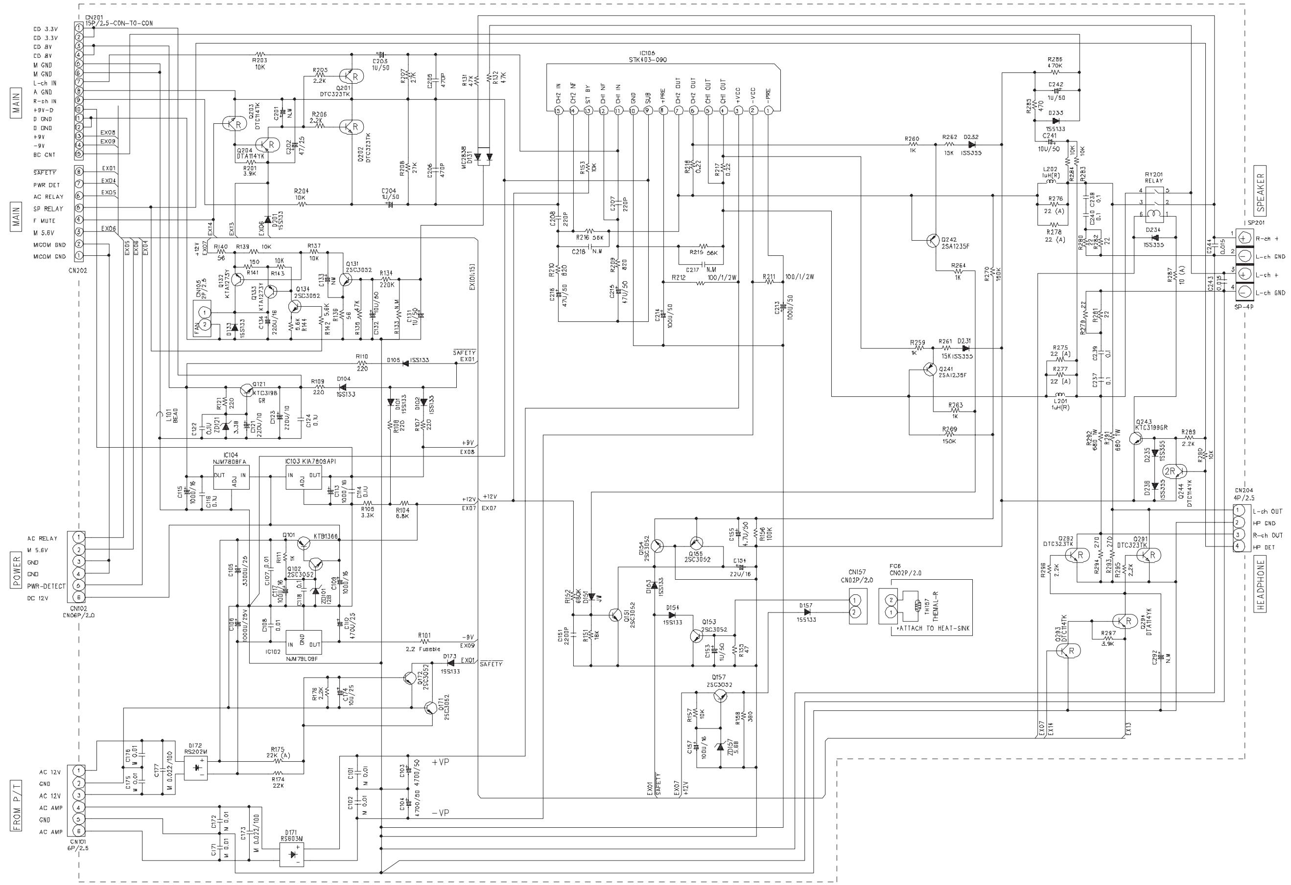
text_image
CN01 CD 3.3V CD 3.3V CD BV CD BV M GND M GND L-ch IN A GND R-ch IN +9V-D G GND +9V -9V BC CNT SAFETY PWR DET AC RELAY SP RELAY F MUTE M S.BV MODM BND MODM CND CN202 +12V +12V +12V +12V +12V +12V +12V +12V +12V +12V +12V +12V +12V +12V +12V +12V +12V +12V +12V +12V +12N +12N +12N +12N +12N +12N +12N +12N +12N +12N +12N +12N +12N +12N +12N +12N +12N +12N +12N +12N +12 N +12N +12N +12N +12N +12N +12N +12N +12N +12N +12N +12N +12N +12N +12N +12N +12N +12N +12N +12N +12S +12S +12S +12S +12S +12S +12S +12S +12S +12S +12S +12S +12S +12S +12S +12S +12S +12S +12S +12S +12 S +12S +12S +12S +12S +12S +12S +12S +12S +12S +12S +12S +12S +12S +12S +12S +12S +12S +12S +12S +12N + - C77 0.05 0.05 0.05 0.05 0.05 0.05 0.05 0.05 0.05 0.05 0.05 0.05 0.05 0.05 0.05 0.05 0.05 0.05 0.05 0.05 0.06 0.06 0.06 0.06 0.06 0.06 0.06 0.06 0.06 0.06 0.06 0.06 0.06 0.06 0.06 0.06 0.06 0.06 0.06 0.06 0.07 0.07 0.07 0.07 0.07 0.07 0.07 0.07 0.07 0.07 0.07 0.07 0.07 0.07 0.07 0.08 0.08 0.08 0.08 0.08 0.08 0.08 0.08 0.08 0.08 0.08 0.08 0.08 0.08 0.08 0.08 0.08 0.09 0.09 0.09 0.09 0.09 0.09 0.09 0.09 0.09 0.09 0.09 0.14 0.14 0.14 0.14 0.14 0.14 0.14 0.14 0.14 0.14 0.14 0.14 0.14 0.14 0.14 0.37 N. ICD7_78B8FA. ICD7_78B8FA. ICD7_78B8FA. ICD7_78B8FA. ICD7_78B8FA. ICD7_78B8FA. ICD7_78B8FA. ICD7_78B8FA. ICD7_78B8FA. ICD7_78B8FA. ICD7_78B8FVA. ICD7_78B8FVA. ICD7_78B8FVA. ICD7_78B8FVA. ICD7_78B8FVA. ICD7_78B8FVA. ICD7_78B8FVA. ICD7_78B8FVA. ICD7_78B8FVA. ICD7_78B8FVA . ICD7_78B8FVA . ICD7_78B8FVA . ICD7_78B8FVA . ICD7_78B8FVA . ICD7_78B8FVA . ICD7_78B8FVA . ICD7_78B8FVA . ICD7_78B8FVA . ICD7_78B8FVA . IOUTO3KIRWQIPJINHILKIRWQIPJINHILKIRWQIPJINHILKIRWQIPJINHILKIRWQIPJINHILKIRWQIPJINHILKIRWQIPJINHILKIRWQIPJINHILKIRWQIPJINHILKIRWQIPJINHILKIRWQIPJINHILKIRWQIPJINHIL KIRWQIPJINHILKIRWQIPJINHILKIRWQIPJINHILKIRWQIPJINHILKIRWQIPJINHILKIRWQIPJINHILKIRWQIPJINHILKIRWQIPJINHILKIRWQIPJINHILKIRWQIPJINHILKIRWQIPJINHILK IRWQIPJINHILKIRWQIPJINHILKIRWQIPJINHILKIRWQIPJINHILKIRWQIPJINHILKIRWQIPJINHILKIRWQIPJINHILKIRWQIPJINHILKIRWQIPJINHILKIRWQIPJINHILKIRWQIPJINHILKIR WQIPJINHILKIRWQIPJINHILKIRWQIPJINHILKIRWQIPJINHILKIRWQIPJINHILKIRWQIPJINHILKIRWQIPJINHILKIRWQIPJINHILKIRWQIPJINHILKIRWQIPJINHILKIRWQIPJINHILKIRW QTRWQIPJINHILKIRWQIPJINHILKIRWQIPJINHILKIRWQIPJINHILKIRWQIPJINHILKIRWQIPJINHILKIRWQIPJINHILKIRWQIPJINHILKIRWQIPJINHILKIRWQIPJINHILKIRWQIPJINHILKIRR WQIPJINHILKIRWQIPJINHILKIRWQIPJINHILKIRWQIPJINHILKIRWQIPJINHILKIRWQIPJINHILKIRWQIPJINHILKIRWQIPJINHILKIRWQIPJINHILKIRWQIPJINHILKIRWQIPJINHILKIRR QTRWQIPJINHILKIRWQIPJINHILKIRWQIPJINHILKIRWQIPJINHILKIRWQIPJINHILKIRWQIPJINHILKIRWQIPJINHILKIRW QTRWQIPJINHILKIRR QTRWQIPJINHILKIRR QTRWQIPJINHILKIRR QTRWQIPJINHILKIRR QTRWQIPJINHILKIRR QTRWQIPJINHILKIRR QTRWQIPJINHILKIRR QTRWQIPJINHILKIRR QTRWQIPJINHILKIRR QTRW QTRWQIFITAT TO HEAT-SNK■ Micon section
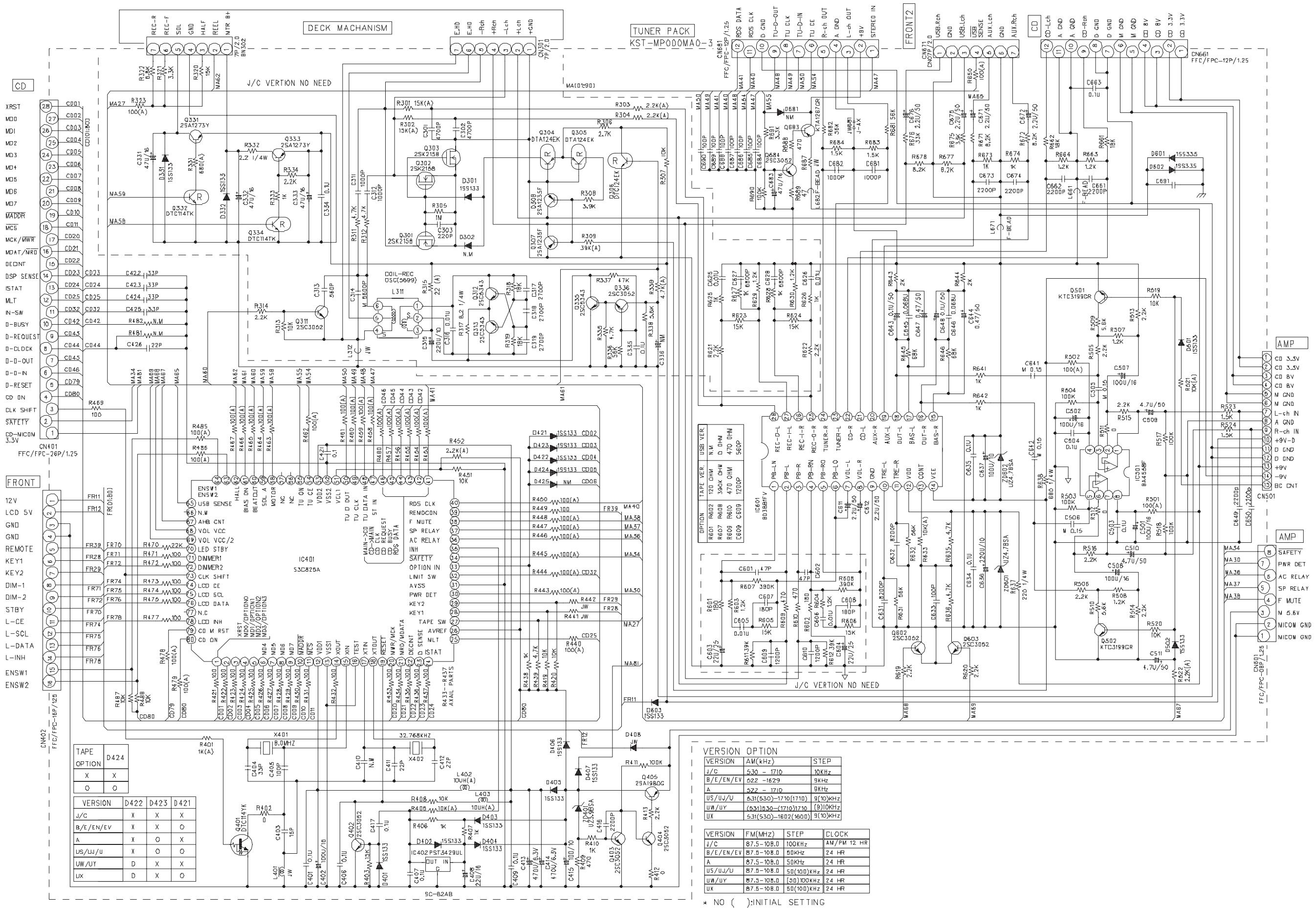
text_image
CD XRS1 M00 M01 M02 M03 M04 M05 M06 M07 M08 M09 M10 M11 M12 M13 M14 M15 M16 M17 M18 M19 M20 M21 M22 M23 M24 M25 M26 M27 M28 M29 M30 M31 M32 M33 M34 M35 M36 M37 M38 M39 M40 M41 M42 M43 M44 M45 M46 M47 M48 M49 M50 M51 M52 M53 M54 M55 M56 M57 M58 M59 M60 M61 M62 M63 M64 M65 M66 M67 M68 M69 M70 M71 M72 M73 M74 M75 M76 M77 M78 M79 M80 TUNER PACK KST-MP00MAO 0 1/2/3 1/4/5 1/6/7 1/7/9 1/8/10 1/9/11 1/10/11 1/11/12 1/12/13 1/13/14 1/14/15 1/15/16 1/16/17 1/17/18 1/18/19 1/19/20 1/20/21 1/21/22 1/22/23 1/23/24 1/24/25 1/25/26 1/26/27 1/27/28 1/28/29 1/29/30 1/30/31 1/31/32 1/32/33 1/33/34 1/34/35 1/35/36 1/36/37 1/37/38 1/38/39 1/39/40 1/40/41 1/41/42 1/42/43 1/43/44 1/44/45 1/45/46 1/46/47 1/47/48 1/48/49 1/49/50 1/50/51 1/51/52 1/52/53 1/53/54 1/54/55 1/55/56 1/56/57 1/57/58 1/58/59 1/59/60 1/60/61 1/61/62 1/62/63 1/63/64 1/64/65 1/65/66 1/66/67 1/67/68 1/68/69 1A-CHD-CHD-CHD-CHD-CHD-CHD-CHD-CHD-CHD-CHD-CHD-CHD-CHD-CHD-CHD-CHD-CHD-CHD-CHD-CHD-CHD-CHD-CHD-CHD-CHD-CHD-CHD-CHD-CHD-CHD-CHD-CHD-CHD-CHD-CDCB-DCB-DCB-DCB-DCB-DCB-DCB-DCB-DCB-DCB-DCB-DCB-DCB-DCB-DCB-DCB-DCB-DCB-DCB-DCB-DCB-DCB-DCB-DCB-DCB-DCB-DCB-DCB-DCB-DCB-DCB-DCB-DCB-DCB- DCB-DCB-DCB-DCB-DCB-DCB-DCB-DCB-DCB-DCB-DCB-DCB-DCB-DCB-DCB-DCB-DCB-DCB-DCB-DCB-DCB-DCB-DCB-DCB-DCB-DCB-DCB-DCB-DCB-DCB-DCB-DCB-DCB-DCBC-DCC-BCC-BCC-BCC-BCC-BCC-BCC-BCC-BCC-BCC-BCC-BCC-BCC-BCC-BCC-BCC-BCC-BCC-BCC-BCC-BCC-BCC-BCC-BCC-BCC-BCC-BCC-BCC-BCC-BCC-BCC-BCC-BCC-BCC-BCC-BCC-BCC-BCC-BCC-BCC-BCC-BCC-BCC-BCC-BCC-BCC-BCC-BCC-BCC-BCC-BCC-SATETY CN-TNCON DCF/TNFE-FR-VFV FFC/FPC-RF-VFV FFC/FPC-RF-VFV FFC/FPC-RF-VFV FFC/FPC-RF-VFV FFC/FPC-RF-VFV FFC/FPC-RF-VFV FFC/FPC-RF-VFV FFC/FPC-RF-VFV FFC/FPC-RF-VFV FFC/FPC-RF-VFV FFC/FPC-RF-VFV FFC/FPC-RF -CSPS SENSIS STAT MTS N-SW D-USS CCK D-D-D-D-D-D-D-D-D-D-D-D-D-D-D-D-D-D-D-D-D-D-D-D-D-D-D-D-D-D-D-D-D-D-D-D-D-D-D-D-D-D-D-D-D-D-D-D-D-D-D-D-D-D-D-D-D-D-D-D-D-D-D-D-D-D-D-D-D-D-D-D-D-D-D-D-D-D-D-D-D-D-D-D-D-D-D-D-D-D-D-D-D-D-D-D-D-D-D-D-D-AH-CAD-SATETY CN-TNCON DCF/TNFE-FR-VFV FFC/FPC-RF-VFV FFC/FPC-RF-VFV FFC/FPC-RF-VFV FFC/FPC-RF-VFV FFC/FPC-RF-VFV FFC/FPC-RF-VFV FFC/FPC-RF-VFV FFC/FPC-RF-VFV FFC/FPC-RF-VFV ACP CDJ CDJ CDJ CDJ CDJ CDJ CDJ CDJ CDJ CDJ CDJ CDJ CDJ CDJ CDJ CDJ CDJ CDJ CDJ CDJ CDJ CDJ CDJ CDJ CDJ CDJ CDJ CDJ CDJ CDJ CDJ CDJ CDJ CDJ CDJ CDJ CDJ CDJ CDJ CDJ CDJ CDJ CDJ CDJ CDJ CDJ CDJ CDJ CDJ CDJ CDI ACP BCT BCT BCT BCT BCT BCT BCT BCT BCT BCT BCT BCT BCT BCT BCT BCT BCT BCT BCT BCT BCT BCT BCT BCT BCT BCT BCT BCT BCT BCT BCT BCT BCT BCT BCT BCT BCT BCT BCT BCT BCT BCT BCT BCT BCT BCT BCT BCT BCT BCT BCTR ACP BCT BCT BCT BCT BCT BCT BCT BCT BCT BCT BCT BCT BCT BCT BCT BCT BCT BCT BCT BCT BCT BCT BCT BCT BCT BCT BCT BCT BCT BCT BCT BCT BCT BCT BCT BCT BCT BCT BCT BCT BCT BCT BCT BCT BCT BCT BCT BCT BCTR ACF ACF ACF ACF ACF ACF ACF ACF ACF ACF ACF ACF ACF ACF ACF ACF ACF ACF ACF ACF ACF ACF ACF ACF ACF ACF ACF ACF ACF ACF ACF ACF ACF ACF ACF ACF ACF ACF ACF ACF ACF ACF ACF ACF ACF ACF ACF ACF ACF ACF ACP ACF ACF ACF ACF ACF ACF ACF ACF ACF ACF ACF ACF ACF ACF ACF ACF ACF ACF ACF ACF ACF ACF ACF ACF ACF ACF ACF ACF ACF ACF ACF ACF ACF ACF ACF ACF ACF ACF ACF ACF ACF ACF ACF ACF ACF ACF ACF ACF ACF ADF-AFF-AFF-AFF-AFF-AFF-AFF-AFF-AFF-AFF-AFF-AFF-AFF-AFF-AFF-AFF-AFF-AFF-AFF-AFF-AFF-AFF-AFF-AFF-AFF-AFF-AFF-AFF-AFF-AFF-AFF-AFF-AFF-AFF-AFF-AFF-AFF-AFF-AFF-AFF-AFF-AFF-AFF-AFF-AFF-AFF-AFF-AFF-AFF-AFF-AFF-AFP-AFF-AFF-AFF-AFF-AFF-AFF-AFF-AFF-AFF-AFF-AFF-AFF-AFF-AFF-AFF-AFF-AFF-AFF-AFF-AFF-AFF-AFF-AFF-AFF-AFF-AFF-AFF-AFF-AFF-AFF-AFF-AFF-AFF-AFF-AFF-AFF-AFF-AFF-AFF-AFF-AFF-AFF-AFF-AFF-AFF-AFF-AFF-AFF-AFF-AFOA-FAFOA-FAFOA-FAFOA-FAFOA-FAFOA-FAFOA-FAFOA-FAFOA-FAFOA-FAFOA-FAFOA-FAFOA-FAFOA-FAFOA-FAFOA-FAFOA-FAFOA-FAFOA-FAFOA-FAFOA-FAFOA-FAFOA-FAFOA-FAFOA-FAFOA-FACFA-FACFA-FACFA-FACFA-FACFA-FACFA-FACFA-FACFA-FACFA-FACFA-FACFA-FACFA-FACFA-FACFA-FACFA-FACFA-FACFA-FACFA-FACFA-FACFA-FACFA-FACFA-FACFA-FACFA-FACFA-FACFA-FACFA-FACFA-FACFA-FACFA-FACFA-FACFA-FACFA-FACFA-LAB(A) - - - - - - - - - - - - - - - - - - - - - - - - - - - - - - - - - - - - - - - - - - - - - - - - - - - - - - - - - - - - - - - - - - - - - - - - - - - - - - - - - - - - - - - - - - - - - - - - - - - -CD section
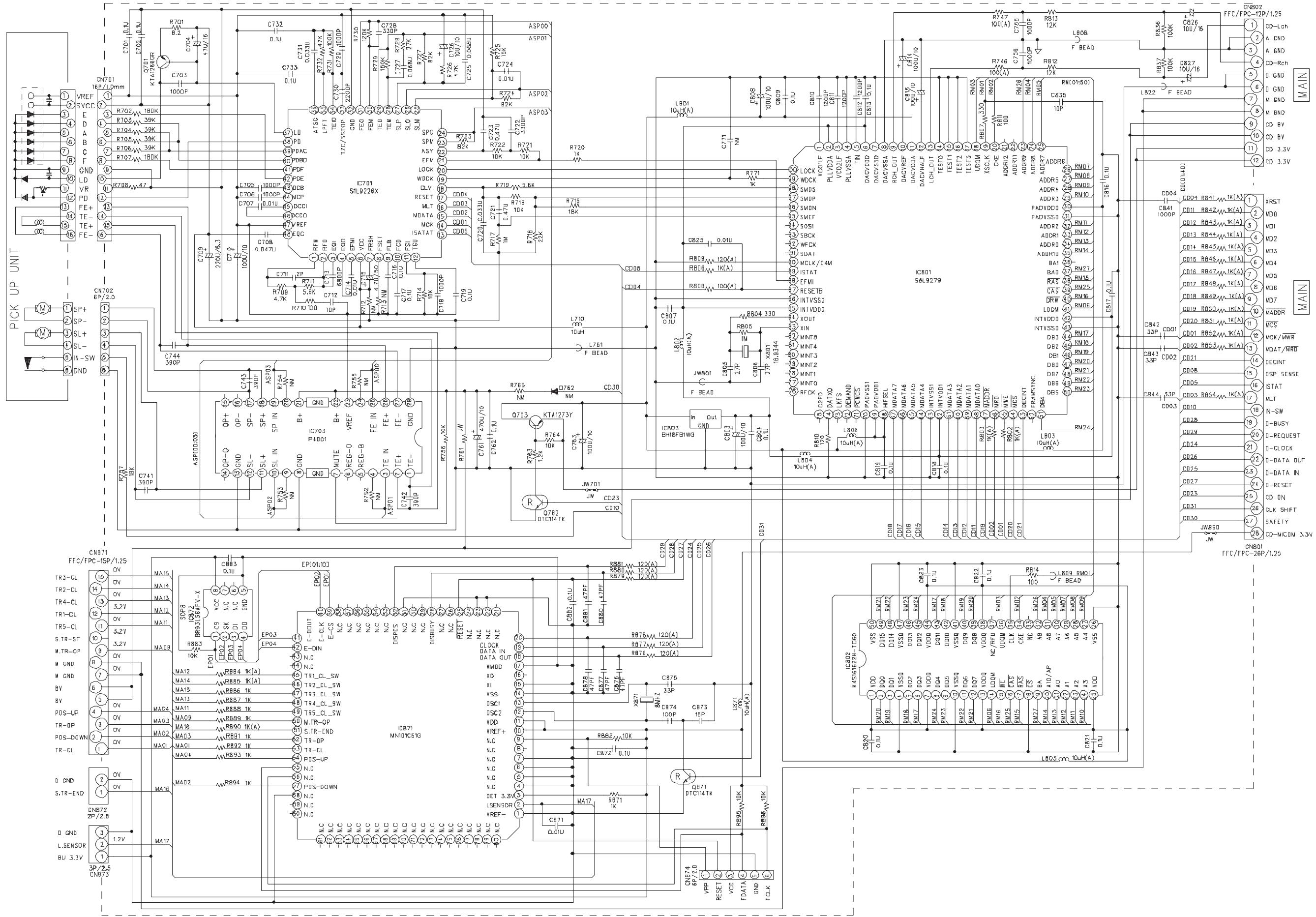
text_image
PICK UP UNIT CN701 VREF SVCC F-E D-B R-02 VR VD PD FE+ TE- FE+ ON ONL VR VD PD FE+ TE- FE+ ON ONL SPS- DSL+ DSL- IN-W GND CN702 BV 2.0 C744 560P C743 380P C742 370P C741 360P C740 350P C739 340P C738 330P C737 320P C736 310P C735 300P C734 290P C733 280P C732 270P C731 260P C730 250P C729 240P C728 230P C727 220P C726 210P C725 200P C724 190P C723 180P C722 170P C721 160P C720 150P C719 140P C718 130P C717 120P C716 110P C715 100P C714 90P C713 80P C712 70P C711 60P C710 50P C709 40P C708 30P C707 20P C696 10P C695 0.5P C694.5A 4.4Z C693.5A 4.4Z 4.4Z 4.4Z 4.4Z 4.4Z 4.4Z 4.4Z 4.4Z 4.4Z 4.4Z 4.4Z 4.4Z 4.4Z 4.4Z 4.4Z 4.4Z 4.4Z 4.4Z 4.4Z 4.4Z 4.4 Z 5W 5W 5W 5W 5W 5W 5W 5W 5W 5W 5W 5W 5W 5W 5W 5W 5W 5W 5W 5W 5W 5W 5W 5W 5W 5W 5W 5W 5W 5W 5W 5W 5W 5W■ Display and Primary section
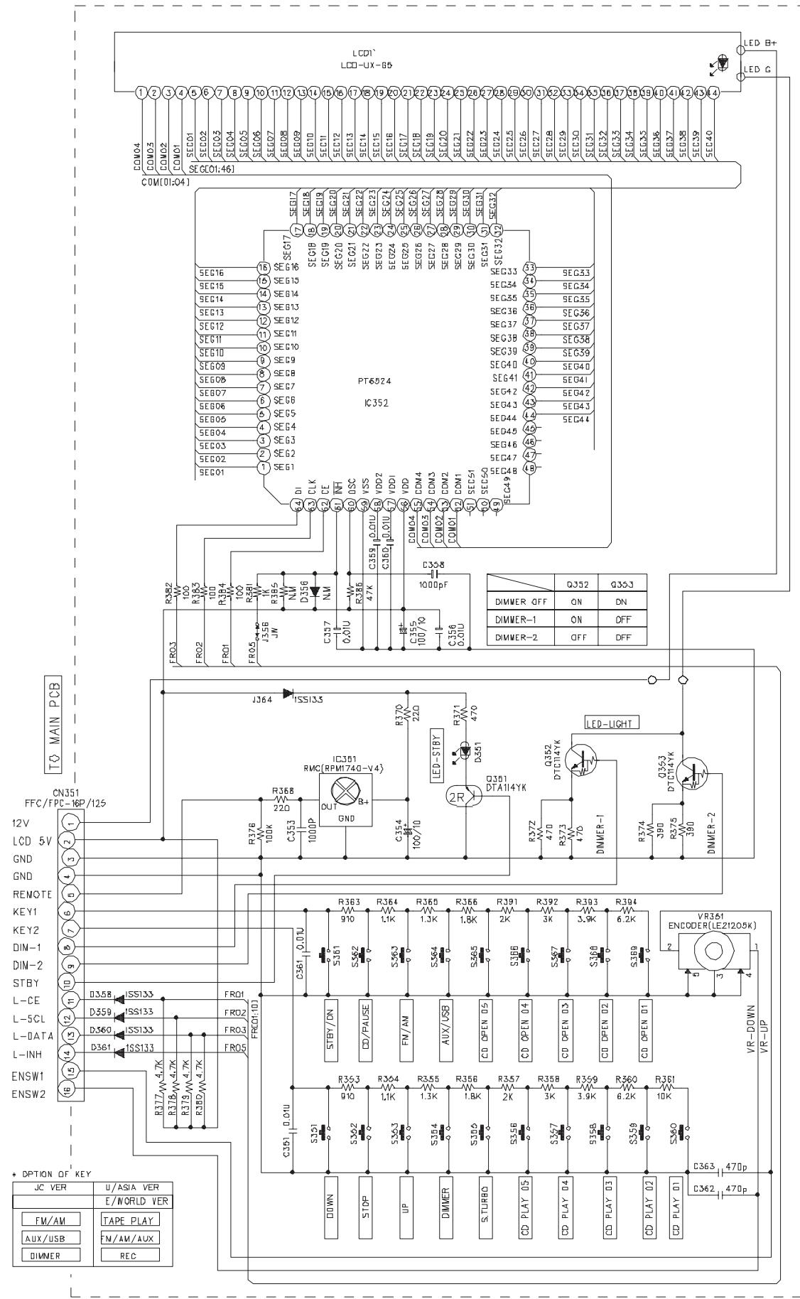
text_image
LCD1 LED-UX-B5 COM[01:04] 1 2 3 4 5 6 7 8 9 10 11 12 13 14 15 16 17 18 19 20 21 22 23 24 25 26 27 28 29 30 31 32 33 34 35 36 37 38 39 40 SEC16 SEC15 SEC14 SEC13 SEC12 SEC11 SEC10 SEC9 SEC8 SEC7 SEC6 SEC5 SEC4 SEC3 SEC2 SEC1 PT6024 IC352 SEG07 SEG06 SEG05 SEG04 SEG03 SEG02 SEG01 R382 FR03 FR02 FR01 R383 FR02 R384 FR01 R385 FR06 R386 FR07 R387 FR08 R388 FR09 R389 FR10 R390 FR11 R391 FR12 R392 FR13 R393 FR14 R394 FR15 R395 FR16 R396 FR17 R397 FR18 R398 FR19 R399 FJ64 ISS13.5 R370 220 LED-SI8Y R371 470 D5401 C356 DUT GND C354 B1 C356 DQ1/14YK R368 220 R369 220 R370 220 R371 220 R372 220 R373 220 R374 220 R375 220 R376 220 R377 220 R378 220 R379 220 R380W4.7K R381W4.7K R382W4.7K R383W4.7K R384W4.7K R385W4.7K R386W4.7K R387W4.7K R388W4.7K R389W4.7K R390W4.7K R391W4.7K R392W4.7K R393W4.7K R394W4.7K S361 W4.7K S362 W4.7K S363 W4.7K S364 W4.7K S365 W4.7K S366 W4.7K S367 W4.7K S368 W4.7K S369 W4.7K S370 W4.7K S371 W4.7K S372 W4.7K S373 W4.7K S374 W4.7K S375 W4.7K S376 W4.7K S377 W4.7K S378 W4.7K S379 W4.7K S380W4.7K S381W4.7K S382W4.7K S383W4.7K S384W4.7K S385W4.7K S386W4.7K S387W4.7K S388W4.7K S389W4.7K S390W4.7K
Printed circuit boards
■ Main board
Lead free solder used in the board (material : Sn-Ag-Cu, melting point : 219 Centigrade)
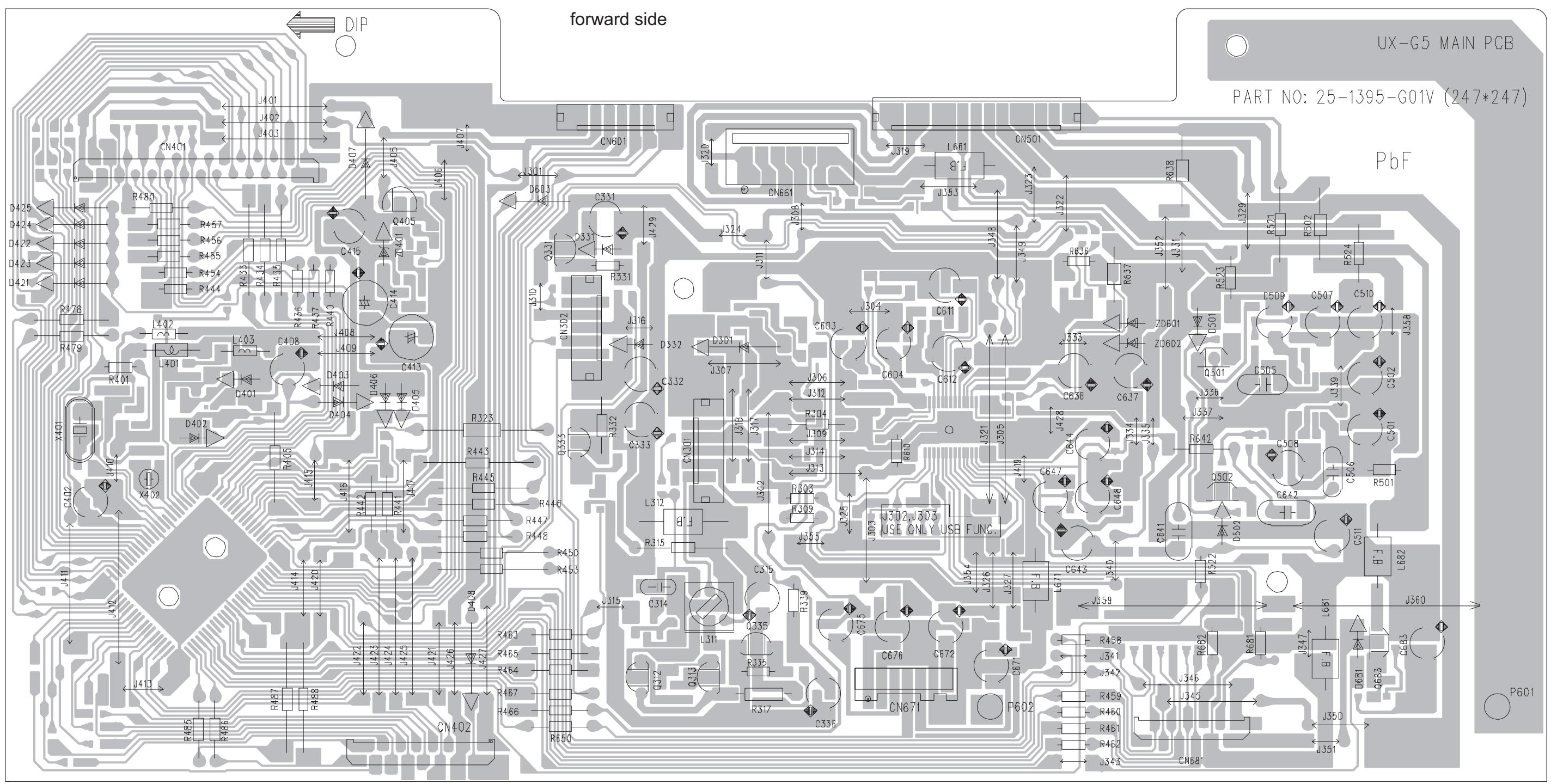
text_image
forward side DN-G5 MAIN PCB PART NO: 25-1395-G01V (247*247) PbF DN6D1 CN501 R618 L1729 J327 DN661 JU19 L661 CN501 J324 J356 JU11 L353 JU12 R636 R637 JU12 R324 R502 R524 D509 C507 C510 J358 ZDB01 ZD602 Q501 C505 J339 C637 J327 R642 C508 C642 C506 R501 J360 J350 J351 UX-G5 MAIN PCB DN401 J401 J402 J403 CN401 R480 R457 R456 R455 R454 R453 R452 R451 R449 R448 R447 R446 R445 R444 R443 R442 R441 R440 R439 R438 R437 R436 R435 R434 R433 R432 R431 R430 R429 R428 R427 R426 R425 R424 R423 R422 R421 R420 R419 R418 R417 R416 R415 R414 R413 R412 R411 R410 R409 R408 R407 R406 R405 R404 R403 R402 R399 R398 R397 R396 R395 R394 R393 R392 R391 R390 R389 R388 R387 RN801NBNBGBNBNBNBNBNBNBNBNBNBNBNBNBNBNBNBNBNBNBNBNBNBNBNBNBNBNBNBNBNBNBNBNBNBNBNBNBNBNBNBNBNBNBNBNBNBNBNBNBNBNBNBNBNBNBNBNBNBNBNBNBNBNBNBNBNBNBNBNBNBNBNBNBNBNBNBNBNBNBNBNBNBNBNBNBNBNBNBNBNBNBNBNBNBNBNBNBNBNBNBNBNPNKPNKPNKPNKPNKPNKPNKPNKPNKPNKPNKPNKPNKPNKPNKPNKPNKPNKPNKPNKPNKPNKPNKPNKPNKPNKPNKPNKPNKPNKPNKPNKPNKPNKPNKPNKPNKPNKPNKPNKPNKPNKPNKPNKPNKPNKPNKPNKPNKPNKPNKNKNKNKNKNKNKNKNKNKNKNKNKNKNKNKNKNKNKNKNKNKNKNKNKNKNKNKNKNKNKNKNKNKNKNKNKNKNKNKNKNKNKNKNKNKNKNKNKNKNKNKNKNKNKNKNKNKNKNKNKNKNKNKNKNKNKNKNKNKNKNKNKNKNKNKNKNKNKNKNKNKNKNKNKNKNKNKNKNKNKNKNKNKNKNKNKNKNKNKNNNNHNNHNNHNNHNNHNNHNNHNNHNNHNNHNNHNNHNNHNNHNNHNNHNNHNNHNNHNNHNNHNNHNNHNNHNNHNNHNNHNNHNNHNNHNNHNNHNNHNNHNNHNNHNNHNNHNNHNNHNNHNNHNNHNNHNNHNNHNNHNNHNNHNNHNNHHHHHHHHHHHHHHHHHHHHHHHHHHHHHHHHHHHHHHHHHHHHHHHHHHHHHHHHHHHHHHHHHHHHHHHHHHHHHHHHHHHHHHHHHHHHHHHHHHHHHHHHHHHHHHHHHHHHHHHHHHHHHHHHHHHHHHHHHHHHHHHHHHHHHHHHHHHHHHHHHHWHHWHWHWHWHWHWHWHWHWHWHWHWHWHWHWHWHWHWHWHWHWHWHWHWHWHWHWHWHWHWHWHWHWHWHWHWHWHWHWHWHWHWHWHWHWHWHWHWHWHWHWHWHWHWHWHWHWHWHWHWHWHWHWHWHWHWHWHWHWHWHWHWHWHWHWHWHWHWHWHWHWHWHWHWHWHWHWHWHWHWHWHWHWHWHWHWHWHWHWHWHWHTHTHTHTHTHTHTHTHTHTHTHTHTHTHTHTHTHTHTHTHTHTHTHTHTHTHTHTHTHTHTHTHTHTHTHTHTHTHTHTHTHTHTHTHTHTHTHTHTHTHTHTHTHTHTHTHTHTHTHTHTHTHTHTHTHTHTHTHTHTHTHTHTHTHTHTHTHTHTHTHTHTHTHTHTHTHTHTHTHTHTHTHTHTHTHTHTHTHTHT HTTTTATTTTTTTTTTTTTTTTTTTTTTTTTTTTTTTTTTTTTTTTTTTTTTTTTTTTTTTTTTTTTTTTTTTTTTTTTTTTTTTTTTTTTTTTTTTTTTTTTTTTTTTTTTTTTTTTTTTTTTTTTTTTTTTTTTTTTTTTTTTTTTTTTTTTTTTTTTTTTTTTTTATTTTATTTTATTTTATTTTATTTTATTTTATTTTATTTTATTTTATTTTATTTTATTTTATTTTATTTTATTTTATTTTATTTTATTTTATTTTATTTTATTTTATTTTATTTTATTTTATTTTATTTTATTTTATTTTATTTTATTTTATTTTATTTTATTTTAT TAT TAT TAT TAT TAT TAT TAT TAT TAT TAT TAT TAT TAT TAT TAT TAT TAT TAT TAT TAT TAT TAT TAT TAT TAT TAT TAT TAT TAT TAT TAT TAT TAT TAT TAT TAT TAT TAT TAT TAT TAT TAT TAT TAT TAT TAT TAT TAT TAT TAT UNTUOCCDCDCDCDCDCDCDCDCDCDCDCDCDCDCDCDCDCDCDCDCDCDCDCDCDCDCDCDCDCDCDCDCDCDCDCDCDCDCDCDCDCDCDCDCDCDCDCDCDCDCDCDCDCDCDCDCDCDCDCDCDCDCDCDCDCDCDCDCDCDCDCDCDCDCDCDCDCDCDCDCDCDCDCDCDCDCDCDCDCDCDCDCDCDCDCDCDCDCDCDCDCCDDCCDDCCDDCCDDCCDDCCDDCCDDCCDDCCDDCCDDCCDDCCDDCCDDCCDDCCDDCCDDCCDDCCDDCCDDCCDDCCDDCCDDCCDDCCDDCCDDCCDDCCDDCCDDCCDDCCDDCCDDCCDDCCDDCCDDCCDDCCDDCCDDCCDDCCDDCCDDCCDDCCDDCCDDCCDDCCDDCCDDCCDDCCDDCCDDCCDDCC DCGGSHSHSHSHSHSHSHSHSHSHSHSHSHSHSHSHSHSHSHSHSHSHSHSHSHSHSHSHSHSHSHSHSHSHSHSHSHSHSHSHSHSHSHSHSHSHSHSHSHSHSHSHSHSHSHSHSHSHSHSHSHSHSHSHSHSHSHSHSHSHSHSHSHSHSHSHSHSHSHSHSHSHSHSHSH SHH SHH SHH SHH SHH SHH SHH SHH SHH SHH SHH SHH SHH SHH SHH SHH SHH SHH SHH SHH SHH SHH SHH SHH SHH SHH SHH SHH SHH SHH SHH SHH SHH SHH SHH SHH SHH SHH SHH SHH SHH SHH SHH SHH SHH SHH SHH SHH SHH SHH SHI SHI SHI SHI SHI SHI SHI SHI SHI SHI SHI SHI SHI SHI SHI SHI SHI SHI SHI SHI SHI SHI SHI SHI SHI SHI SHI SHI SHI SHI SHI SHI SHI SHI SHI SHI SHI SHI SHI SHI SHI SHI SHI SHI SHI SHI SHI SHI SHI SHI SHi Shi shi shi shi shi shi shi shi shi shi shi shi shi shi shi shi shi shi shi shi shi shi shi shi shi shi shi shi shi shi shi shi shi shi shi shi shi shi shi shi shi shi shi shi shi shi shi shi shi shi shi snn nnnn nnnn nnnn nnnn nnnn nnnn nnnn nnnn nnnn nnnn nnnn nnnn nnnn nnnn nnnn nnnn nnnn nnnn nnnn nnnn nnnn nnnn nnnn nnnn nnnn nnnn nnnn nnnn nnnn nnnn nnnn nnnn nnnn nnnm nnnn nnnn nnnn nnnn nnnn nnnn nnnn nnnn nnnn nnnn nnnn nnnn nnnn nnnn nnnn nnnn nnnn nnnn nnnn nnnn nnnn nnnn nnnn nnnn nnnn nnnn nnnn nnnn nnnn nnnn nnnn nnnn nnnn twnttnttnttnttnttnttnttnttnttnttnttnttnttnttnttnttnttnttnttnttnttnttnttnttnttnttnttnttnttnttnttnttnttnttnttnttnttnttnttnttnttnttnttnttnttnttnttnttnttnttntthttttttttttttttttttttttttttttttttttttttttttttttttttttttttttttttttttttttttttttttttttttttttttttttttttttttttttttttttttttttttttttttttttttttttttttttttttttttttttttttttttttttttttttttttttttttttttttttttttttttttt twnttnttnttnttnttnttnttnttnttnttnttnttnttnttnttnttnttnttnttnttnttnttnttnttnttnttnttnttnttnttnttnttnttnttnttnttnttnttnttnttnttnttnttnttnttnttnttnttntthrnntwnntwnntwnntwnntwnntwnntwnntwnntwnntwnntwnntwnntwnntwnntwnntwnntwnntwnntwnntwnntwnntwnntwnntwnntwnntwnntwnntwnntwnntwnntwnntwnntwnntwnntwnntwnntwnntwnntwnntwnntwnntwnntwnntwnntwnntwnntwnntwnntwnntwnntwthwnntwnntwnntwnntwnntwnntwnntwnntwnntwnntwnntwnntwnntwnntwnntwnntwnntwnntwnntwnntwnntwnntwnntwnntwnntwnntwnntwnntwnntwnntwnntwnntwnntwnntwnntwnntwnntwnntwnntwnntwnntwnntwnntwnntwnntwnntwnntwnntwnntwnctwnntwnctwnctwnctwnctwnctwnctwnctwnctwnctwnctwnctwnctwnctwnctwnctwnctwnctwnctwnctwnctwnctwnctwnctwnctwnctwnctwnctwnctwnctwnctwnctwnctwnctwnctwnctwnctwnctwnctwnctwnctwnctwnctwnctwnctwnctwnctwnctwnctwnctwnctwncftwthwthwthwthwthwthwthwthwthwthwthwthwthwthwthwthwthwthwthwthwthwthwthwthwthwthwthwthwthwthwthwthwthwthwthwthwthwthwthwthwthwthwthwthwthwthwthwthwthwthw thwhwhwhwhwhwhwhwhwhwhwhwhwhwhwhwhwhwhwhwhwhwhwhwhwhwhwhwhwhwhwhwhwhwhwhwhwhwhwhwhwhwhwhwhwhwhwhwhwhwhwhwhwhwhwhwhwhwhwhwhwhwhwhwhwhwhwhwhwhwhwhwhwhwhwhwhwhwhwhwhwhwhwhwhwhwhwhwhwhwhwhwhwhwhwhwhwhwhwhwhwwhwwhhwwwwwwwwwwwwwwwwwwwwwwwwwwwwwwwwwwwwwwwwwwwwwwwwwwwwwwwwwwwwwwwwwwwwwwwwwwwwwwwwwwwwwwwwwwwwwwwwwwwwwwwwwwwwwwwwwwwwwwwwwwwwwwwwwwwwwwwwwwwwwwwwwwwwwwwwwwwwwwwwwwwwwwwwwwwwwwwwwwwwwwwwwwwwwwwwwwwwwwwwwwwwwwwwwwwwwwwwwwwwwwwwwwwwwwwwwwwwwwwwwwwwwwwwwwwwwwwwwwwwwwwwwwwwwwwwwwwwwwwwwwwwwwwwwwwwwwwwwwwwwwwwwwwwwwwwwwwwwwwwwwwwwwwwwwwwwwwwwwwwwwwwwwwwwwwwwwwwwwwwwwwwwwwwwwwwwwwwwwwwwwwwwwwwwwwwwwwwwwwwwwwwwwwwwwwwwwwwwwwwwwwwwwwwwwwwwwwwwwwwwwwwwwwwwwwwwwwwwwwwwwwwwwwwwwwwwwwwwwwwwwwwwwwwwwwwwwwwwwwwwwwwwwwww wwwveu wth whh whh whh whh whh whh whh whh whh whh whh whh whh whh whh whh whh whh whh whh whh whh whh whh whh whh whh whh whh whh whh whh whh whh whh whh whh whh whh whh whh whh whh whh whh whh whh whh whh whh whg whg whg whg whg whg whg whg whg whg whg whg whg whg whg whg whg whg whg whg whg whg whg whg whg whg whg whg whg whg whg whg whg whg whg whg whg whg whg whg whg whg whg whg whg whg whg whg whg whg whqshghghghghghghghghghghghghghghghghghghghghghghghghghghghghghghghghghghghghghghghghghghghghghghghghghghghghghghghghghghghghghghghghghghghghghghghghghghghghghghghghghghghghghghghghghgghhhhhhhhhhhhhhhhhhhhhhhhhhhhhhhhhhhhhhhhhhhhhhhhhhhhhhhhhhhhhhhhhhhhhhhhhhhhhhhhhhhhhhhhhhhhhhhhhhhhhhhhhhhhhhhhhhhhhhhhhhhhhhhhhhhhhhhhhhhhhhhhhhhhhhhhhhhhhhhhhhhhhhhhhhhhhhhhhhhhhhhhhhhhhhhhhhhhhhhhhhhhhhhhhhhhhhhhhhhhhhhhhhhhhhhhhhhhhhhhhhhhhhhhhhhhhhhhhhhhhhhhhhhhhhhhhhhhhhhhhhhhhhhhhhhhhhhhhhhhhhhhhhhhhhhhhhhhhhhhhhhhhhhhhhhhhhhhhhhhhhhhhhhhhhhh hhhhh hhhhh hhhhh hhhhh hhhhh hhhhh hhhhh hhhhh hhhhh hhhhh hhhhh hhhhh hhhhh hhhhh hhhhh hhhhh hhhhh hhhhh hhhhh hhhhh hhhhh hhhhh hhhhh hhhhh hhhhh hhhhh hhhhh hhhhh hhhhh hhhhh hhhhh hhhhh hhhhh hhhhh hhhhh hhhhh hhhhh hhhhh hhhhh hhhhh hhhhh hhhhh hhhhh hhhhh hhhhh hhhhh hhhhh hhhhh hhhhh hhhhh aa
text_image
reverse side 1ST IN 2+9V 3-1-ch OUT 4.A GND 5.RCH OUT 6.DUCE 7.DATA IN 8.TU CLK 9.DATA OUT 10.D GND 11.0DS CLK 12.RDS DATA CB81 CB83 CB85 CB89 CB86 CB87 CB88 CB89 CB88 CB89 CB88 CB89 CB88 CB89 CB88 CB89 CB88 CB89 CB88 CB89 CB88 CB89 CB88 CB89 CB88 CB89 CB88 CB89 CB88 CB89 CB88 CB89 CB87 CB86 CB85 CB84 CB83 CB82 CB81 CB79 CB78 CB77 CB76 CB75 CB74 CB73 CB72 CB71 CB70 CB69 RB00 RB01 RB02 RB03 RB04 RB05 RB06 RB07 RB08 RB09 RB10 RB11 RB12 RB13 RB14 RB15 RB16 RB17 RB18 RB19 RB20 RB21 RB22 RB23 RB24 RB25 RB26 RB27 RB28 RB29 RB30 RB31 RB32 RB33 RB34 RB35 RB36 RB37 RB38 RB39 RB40 RB41 RB42 RB43 RB44 RB45 RB46 RB47 RB48 RB49 RB50 RB51 RB52 RB53 RB54 RB55 RB56 RB57 RB58 RB59 RB60 RB61 RB62 RB63 RB64 RB65 RB66 RB67 RB68 RB69 RB70 RB71 RB72 RB73 RB74 RB75 RB76 RB77 RB78 RB79 RB80 RB81 RB82 RB83 RB84 RB85 RB86 RB87 RB88 RB89 RB90 RB91 RB92 RB93 RB94 RB95 RB96 RB97 RB98 RB99 RB100forward side
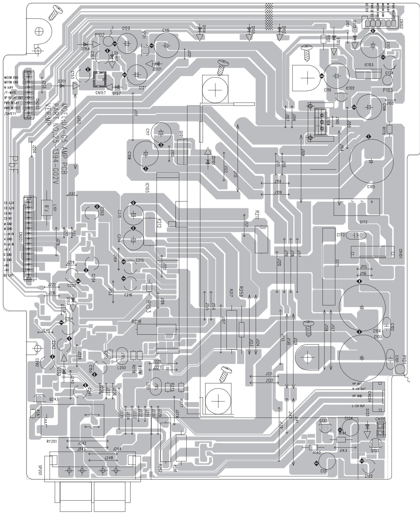
text_image
Circuit board layout diagram with component labels and pin connectionsreverse side
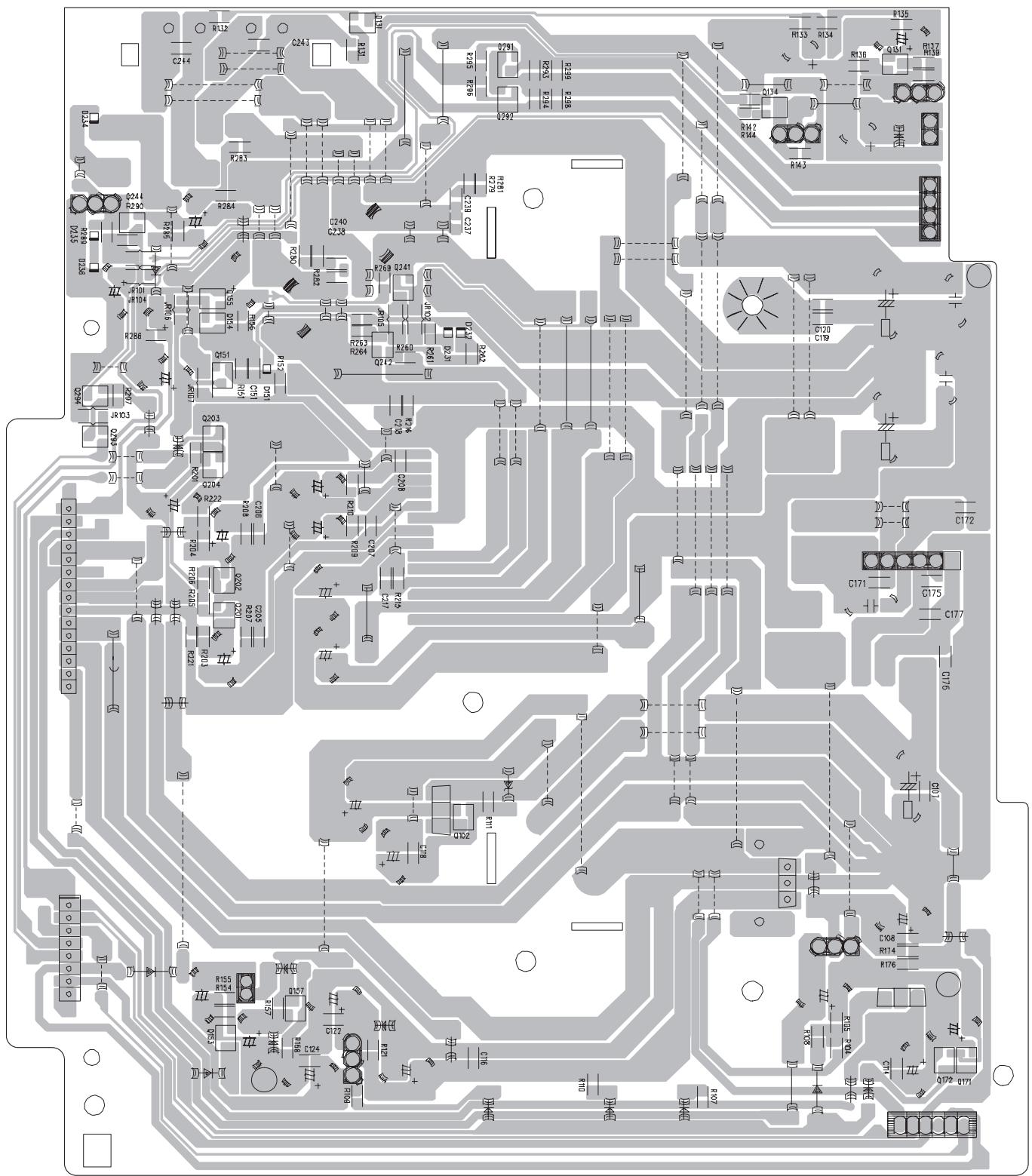
text_image
Circuit board layout diagram with component labels and pin connectionsforward side
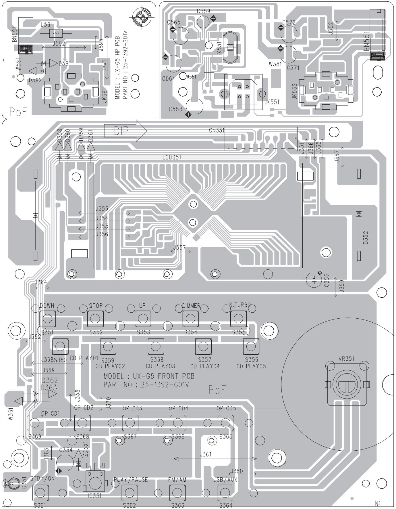
text_image
BN591 L591 J592 J593 W591 D591 D592 JK591 MODEL : UX-G5 HP PCB PART NO : 25-1392-G01V PbF C559 C565 X551 C564 R591 C553 JX551 C572 J552 W581 C571 JX552 BN551 D358 D360 D359 J361 DIP CN351 LCD351 J353 J354 J355 J356 J357 J364 J359 C356 J367 J368S360 CD PLAY01 S359 S358 S357 S356 CD PLAY02 CD PLAY03 CD PLAY04 CD PLAY05 J369 D362 D363 J368S360 OP CD2 UP DIMMER S.TURBO OP CD1 OP CD3 OP CD4 OP CD5 S369 S368 S367 S366 S365 J363 ZD 351 J361 STBY/ON IC351 PLAY/PAUSE FM/AM USB/AUX S361 S362 S363 S364 W361 VR351 N1forward side
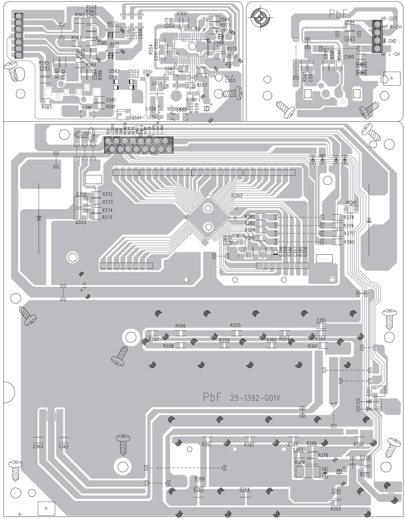
text_image
R58B R560 R562 C562 R572 L558 L557 R563 R561 R569 R571 R584 C584 D582 D581 D553 D552 D551 C566 C568 C570 C570 R571 R572 R573 R574 R575 R576 R577 R578 R579 R580 R581 R582 R583 Q551 L551 Q552 L552 Q553 L553 Q554 L554 Q555 L555 Q556 L556 Q557 L557 Q558 L558 Q559 L559 Q560 L560 Q561 L561 Q562 L562 Q563 L563 Q564 L564 Q565 L565 Q566 L566 Q567 L567 Q568 L568 Q569 L569 Q570 L570 Q571 L571 Q572 L572 Q573 L573 Q574 L574 Q575 L575 Q576 L576 Q577 L577 Q578 L578 Q579 L579 Q580 L580 Q581 L581 Q582 L582 Q583 L583 PbF HP-DET HP R-CH A GND HP L-CH Q361 JRC61 R378 R379 R377 R380 R381 R382 R383 R384 R385 R386 R387 R388 R389 R390 R391 R392 R393 R394 R395 R396 R397 R398 R399 R39A Q361 Q362 Q363 Q364 Q363forward side
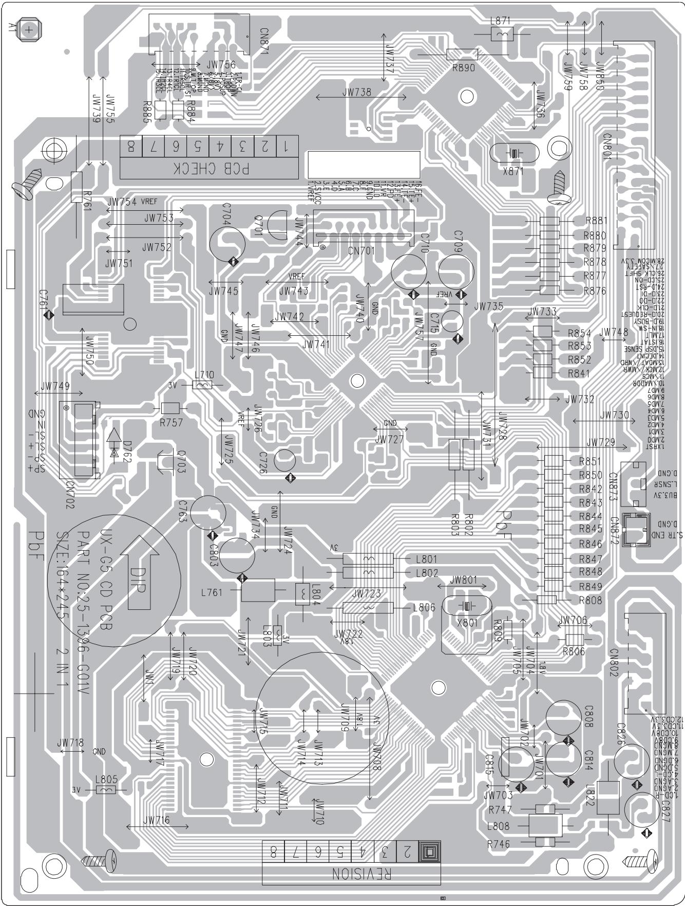
text_image
PCB CHECK JW754 VREF JW753 JW752 JW751 JW750 JW749 GN-ZS-15-SP+1 DNZ02 UX-G5 CD PCB SIZE:164*245 1386-C01V 2 IN 1 JW713 GND L805 JW716 JW719 JW717 JW718 JW719 JW720 JW721 JW722 JW723 JW724 JW725 JW726 JW727 JW728 JW729 JW730 JW731 JW732 JW733 JW734 JW735 JW736 JW737 JW738 JW739 JW740 JW741 JW742 JW743 JW744 JW745 JW746 JW747 JW748 JW749 JW750 JW751 JW752 JW753 JW754 JW755 CN871 99-100-000-000-000-000-000-000-000-000-000-000-000-000-000-000-000-000-000-000-000-000-000-000-000-000-000-88 R885 R884 R883 R882 R881 R880 R879 R878 R877 R876 R854 JW748 R853 R852 R841 JW732 JW733 JW734 JW735 JW736 JW737 JW738 JW739 JW740 JW741 JW742 JW743 JW744 JW745 JW746 JW747 JW748 JW749 JW750 JW751 2 3 4 5 6 7 8 9 10 11 12 13 14 15 16 17 18 19 20 21 22 23 24 25 26 27 28 29 30 31 32 33 34 35 36 37 38 39 40 41 42 43 44 45 46 47 48 49 50 51 52 53 54 55 56 57 58 59 60 61 62 63 64 65 66 67 68 69 70 71 72 73 74 75 76 77 78 79 80reverse side
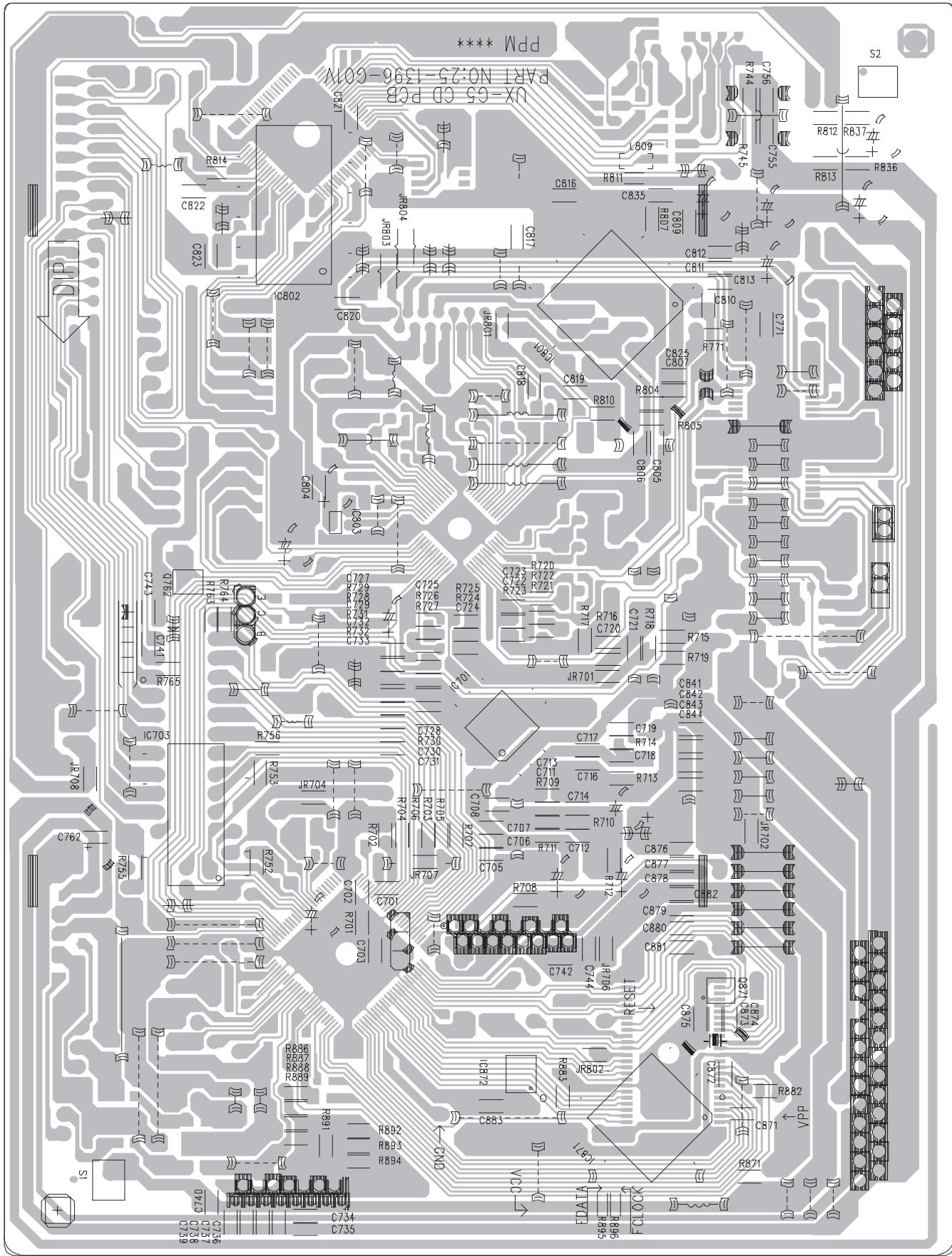
text_image
Ppp M**** Npp X-CCS CD PCB PART NO:25-1396-601V C814 C822 C833 ICB02 CB20 R814 RB04 J803 C17 L609 C816 C835 C812 C811 C813 C819 C825 C807 C804 R810 R804 R805 C725 R726 R727 C724 R725 R726 R727 C724 R723 R722 R721 C723 R716 C720 R715 R719 JR701 C841 C842 C843 C844 C717 C719 R714 C718 C716 C713 C714 C707 C706 C712 C705 R708 R709 R710 C876 C877 C878 C879 C880 C881 RESET 92.80 92.80 92.80 R836 R837 R838 R839 R891 R892 RB95 RB94 DND30 VDDA S588H S589H FCLKOW