
PPM42M7HBP - TV SAMSUNG - Free user manual and instructions
Find the device manual for free PPM42M7HBP SAMSUNG in PDF.
| Product Type | Professional Plasma Display |
| Brand | SAMSUNG |
| Model | PPM42M7HBP |
| Screen Size | 42 inches (diagonal) |
| Native Resolution | 1024 × 768 pixels (XGA) |
| Power Supply | 100-240 V ~ 50/60 Hz |
| Input Connectors | AV (Composite), S-Video, Component (Y/Pb/Pr), PC (RGB D-sub 15-pin, BNC), DVI |
| Output Connectors | AV (Composite), PC OUT (RGB), External Speakers (8 Ω, 10 W min.) |
| Main Functions | Picture-in-Picture (PIP), Video Wall up to 5×5, Screen Burn Protection, TruSurround XT, On/Off Timers, Key Lock |
| Audio Modes | Standard, Music, Movie, Speech, Custom, SRS TruSurround XT |
| Picture Formats | 16:9, Wide 4:3, Zoom, 4:3 |
| Picture Settings | Contrast, Brightness, Sharpness, Color, Tint, Color Tone (4 settings) |
| Screen Burn Protection | Pixel Shift (horiz. and vert.), White Screen, Signal Scroll, Inversion, Bar, Adjustable Timer |
| Controls | Front panel (7 buttons), Infrared remote control (AAA batteries) |
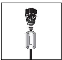
| Supplied Accessories | Remote control, AAA batteries, power cable, PC cable, stand bases (2), screws (4), ferrite cores (2 for speakers, 1 for power cable) |
| Wall Mounting | Optional wall mount (not supplied), installation by qualified technician recommended |
| Care and Cleaning | Clean with a soft dry cloth. Do not use chemical products. |
| Safety | Do not block ventilation openings. Avoid moisture and shocks. Do not display still image for more than 2 hours. |
| Spare Parts and Repairability | Contact a Samsung authorized service center for repairs. Spare parts available via service network. |
Frequently Asked Questions - PPM42M7HBP SAMSUNG
User questions about PPM42M7HBP SAMSUNG
0 question about this device. Answer the ones you know or ask your own.
Ask a new question about this device
Download the instructions for your TV in PDF format for free! Find your manual PPM42M7HBP - SAMSUNG and take your electronic device back in hand. On this page are published all the documents necessary for the use of your device. PPM42M7HBP by SAMSUNG.
USER MANUAL PPM42M7HBP SAMSUNG
If you have any questions or comments relating to Samsung products, please contact the SAMSUNG customer care center.
Professional PDP Display (PLASMA DISPLAY PANEL)
PPM42M7H
PPM50M7H
Owner's Instructions
Before operating the unit, please read this manual thoroughly, and retain it for future reference.
Intended for Commercial Use and Operation
ON-SCREEN MENUS Picture In Picture (PIP)VIDEO WALL
MDC (Multiple Display Control) Screen Burn Protection SRS(●) SRS TruSurroundXT
Register your product at www.samsung.com/global/register Record your Model and Serial number here for future reference.
- Model
- Serial No.
User Instructions
Screen Image retention
Do not display a still image (such as on a video game or when hooking up a PC to this PDP Display) on the plasma PDP Display panel for more than 2 hours as it can cause screen image retention. This image retention is also known as "screen burn". To avoid such image retention, reduce the degree of brightness and contrast of the screen when displaying a still image.
Height
The PDP Display can normally operate only under 2000m in height. It might abnormally function at a place over 2000m in height, so do not install and operate there.
Heat on the top of the PDP Display
The top side of the product may be hot after long periods of use as heat dissipates from the panel through the vent hole in the upper part of the product.
This is normal and does not indicate any defect or operation failure of the product.
However, children should be prevented from touching the upper part of the product.
The product is making a 'cracking' noise.
A 'cracking' noise may occur when the product contracts or expands due to a change of surrounding environment such as temperature or humidity. This is normal and not a defect of the unit.
Cell Defects
The PDP Display uses a panel consisting of 1,230,000(SD-level) to 3,150,000(HD-level) pixels which require sophisticated technology to produce. However, there may be a few bright or dark pixels on the screen. These pixels will have no impact on the performance of the product.
Avoid operating the PDP Display at temperatures below 5^(41^)
A still image displayed too long may cause permanent damage to the PDP Display Panel
Watching the PDP Display in 4:3 format for a long period of time may leave traces of borders displayed on the left, right and center of the screen caused by the difference of light emission on the screen.
Playing a DVD or a game console may cause similar effect to the screen.
Damage caused by the above effect are not covered by the Warranty.
Afterimage on the Screen.
Displaying still images from Video games and PC for longer than a certain period of time may produce partial afterimages.
To prevent this effect, reduce the 'brightness' and 'contrast' when displaying still images for a long time.
Warranty
- Warranty does not cover any damage caused by image retention.
- Burn-in is not covered by the warranty.
Installation
Be sure to contact an authorized service center, when installing your PDP Display in a location with heavy dust, high or low temperatures, high humidity, chemical substance and where it operates for 24 hours such as the airport, the train station or etc.
Failure to do so may cause a serious damage to your PDP Display.
Installing the product in an airtight place may shorten the lifetime of the product.
© 2007 Samsung Electronics Co., Ltd. All rights reserved.
Checking Parts
Owner's Instructions
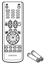
Remote Control/ AAA Batteries

Ferrite Cores for
Speaker Wire (2EA)
(Refer to page 14)
(3301-001201)

Ferrite Core for Power Cord (3301-001110)
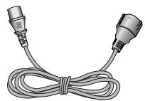
Power Cord
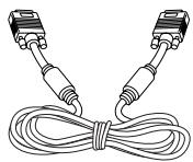
PC Cable
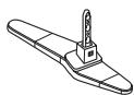
Stand-Base (2EA)

Screws (4EA)
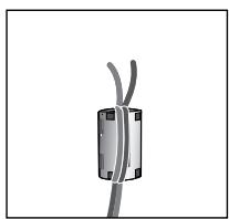
Ferrite Core (Power Cord, Speaker Wire)
The ferrite cores are used to shield the cables from interference. When connecting a cable, open the ferrite core and clip it around the cable near the plug.
Contents
FOREWORD
User Instructions 2
CONNECTING AND PREPARING YOUR DISPLAY
Control Panel. 6
Infrared Remote Control 8
Inserting the Batteries in the Remote Control. 9
Assembling the Stand-Base 9
■ Installing the Display on the Wall Attachment Panel 10
■ Installing the Display Vertically 12
Before Using the Video Wall and the Multiple Display Control function 12
- Connecting Speakers 13
Switching Your PDP Display On and Off. 15
Choosing Your Language 15
USING YOUR DISPLAY
Changing the Picture Standard 16
- Customizing the Picture Settings 17
Adjusting the RGB Color (PC Mode) 18
Setting the Picture (PC Mode) 18
Using Zoom function (PC Mode) 20
Selecting the Picture Size 21
Freezing the Current Picture 22
Changing the Sound Standard 22
- Customizing the Sound Settings 23
Setting the TruSurround XT. 24
- Activating Panel Button Lock 25
- Activating Remote Control Button Lock 26
Setting Up Your Personal ID Number 27
Continued...
Contents
USING YOUR DISPLAY (CONTINUED)
Setting the MDC (Multiple Display Control) 28
Preventing Screen Burn-in 29
Reducing the Effects of Screen Burn 30
Setting the Screen Burn Protection Timer 31
Setting the Multiple Screen 32
Displaying the Setting Information 33
■ Setting and Displaying the Current Time 33
Switching the PDP Display On and Off Automatically 34
Selecting the Fan. 36
Viewing the Picture in Picture (PIP) 37
Viewing an External Signal Source 38
ADDITIONAL INFORMATION AND CONNECTIONS
- Connecting to the Audio/Video Input 39
- Connecting to the S-Video Input. 40
- Connecting to the Component Input 40
41
41 - Connecting to the PC Input 42
Setting up Your PC Software (Windows only) 43
Input Mode (PC/DVI) 44
■Power Saver (PC1 mode only) 45
RECOMMENDATIONS FOR USE
Troubleshooting: Before Contacting Service Personnel 46
Technical Specifications 47
Symbols

Press

Important

Note
Control Panel
The actual configuration of your PDP Display may be different, depending on your model.
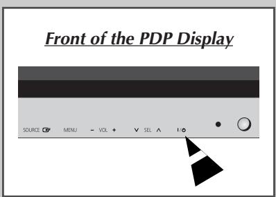
Front of the PDP Display
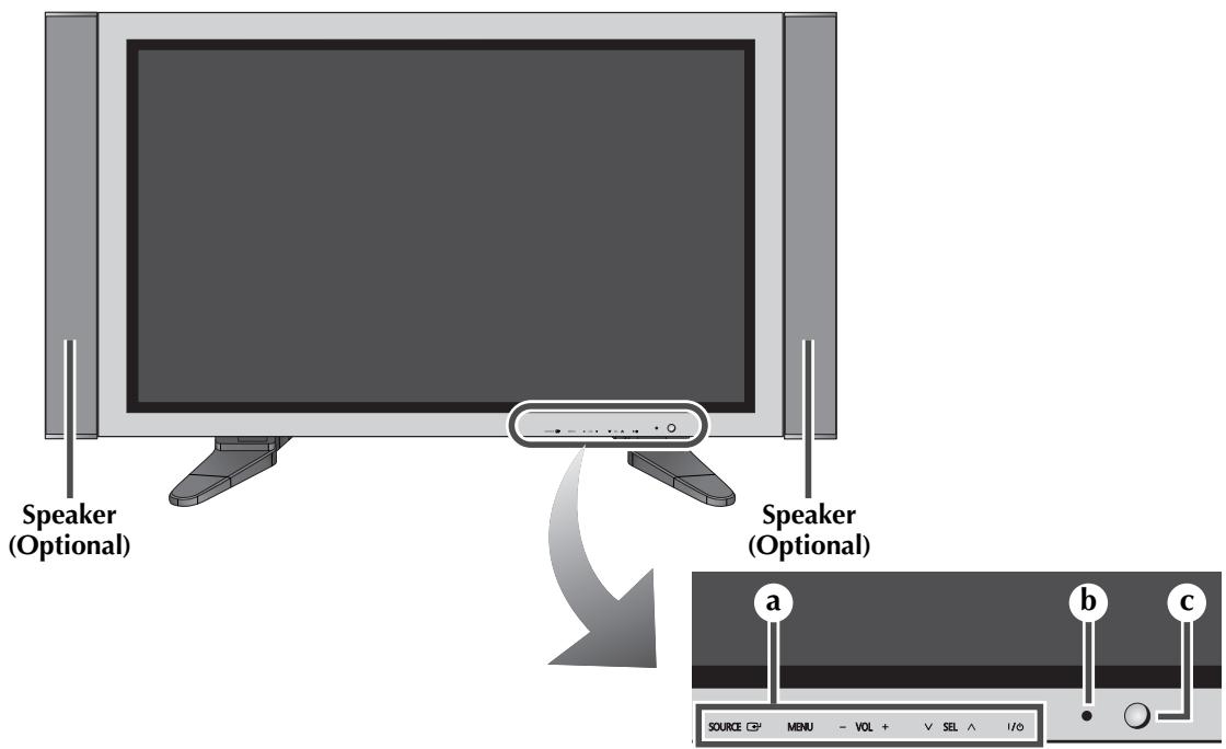
a SOURCE
- Select the external input source.
- Store your settings in the menu.
- When the Main menu is displayed on screen, the Main menu is not operated with source key.
MENU
Display the on-screen menu.
- VOL +
- Adjust the volume.
- Adjust an option value respectively.
(VOL + : Enter to the selected menu.)
VSEL
Control the cursor in the menu.
1/0
Press to turn the PDP Display on and off.
b Power Indicator
- Power Off; Black
- Power On; Green
Remote Control Sensor
Aim the remote control towards this spot on the PDP Display.
You can use the SEL , A buttons to switch on the PDP Display when it is in standby mode depending on the model.
The VOL -, + and SEL , buttons have the same function as the // buttons on the remote control.
If the remote control no longer works or you have misplaced it, you can use the controls on the panel of the PDP Display.
Continued...
Rear Panel
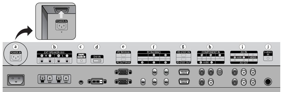
a) POWER IN
Connect the supplied power cord.
b)EXT SPEAKER (8Ω)
Connect external speakers.
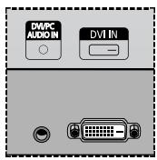
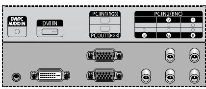
c) DVI/PC AUDIO IN
Connect to the audio output jack on your PC or DVI.
AUDIO is an audio input jack for PC1 and PC2 modes.
d) DVIN
Connect to the video output jack for device with DVI output.
e) PC IN1/PC OUT1
- PC IN1: Connect to the video output jack on your PC.
- PC OUT1: Connect to the video input jack on external devices.
f) PC IN2 (BNC)
Connect for RGB HV video signal input from the PC.
“PC Mode” from this page onward means PC1/PC2 mode using RGB1(PC1) and RGB2(PC2).
For further details about connection, refer to pages 39~42.
Whenever you connect an audio or video system to your PDP Display, ensure that all elements are switched off. Refer to the documentation supplied with your equipment for detailed connection instructions and associated safety precautions.
j) S-VIDEO IN
Video input for external devices with an S-Video output, such as a camcorder or VCR.
g) RS-232C
- IN: Used for the MDC function when connecting PC or RS-232C output of another PDP Display.
- OUT: Used for the MDC function when connecting with RS-232C input of another PDP Display.
For further details about connections, refer to Page 12.
h) COMPONENT IN
Video (Y / PB / PR) and audio (L/R) inputs for component.
i) AV (VIDEO/AUDIO L/R)
IN: Video and audio inputs for external devices, such as a camcorder or VCR.
- OUT: Outputs for external devices.
Infrared Remote Control
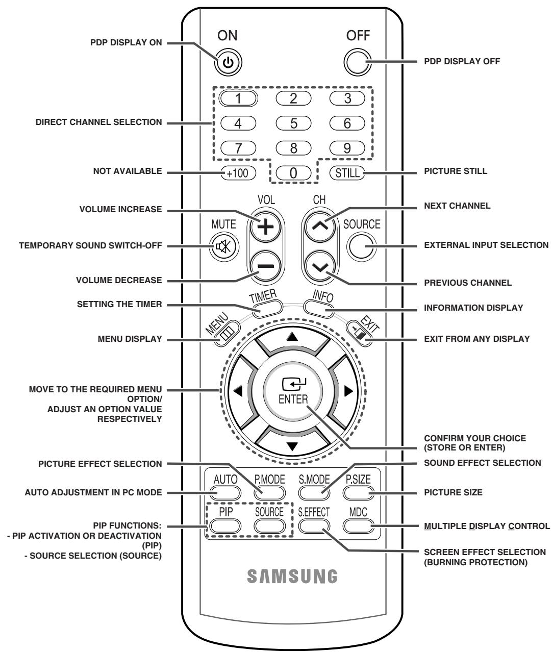
The performance of the remote control may be affected by bright light.
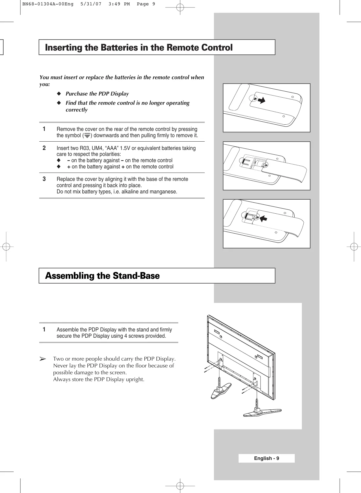
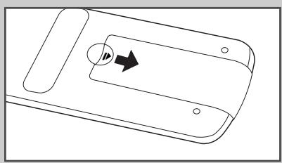
Inserting the Batteries in the Remote Control
You must insert or replace the batteries in the remote control when you:
Purchase the PDP Display
Find that the remote control is no longer operating correctly
1 Remove the cover on the rear of the remote control by pressing the symbol () downwards and then pulling firmly to remove it.
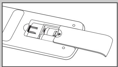
2 Insert two R03, UM4, "AAA" 1.5V or equivalent batteries taking care to respect the polarities:
- on the battery against - on the remote control
- on the battery against + on the remote control
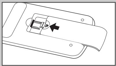
3 Replace the cover by aligning it with the base of the remote control and pressing it back into place. Do not mix battery types, i.e. alkaline and manganese.
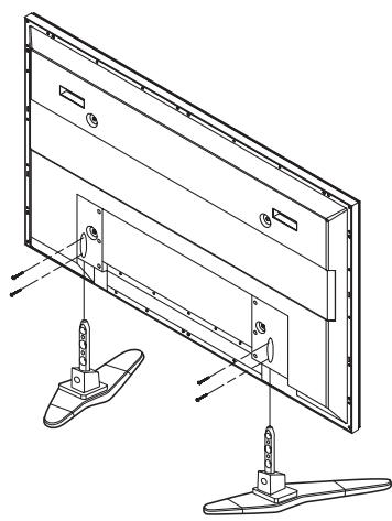
Assembling the Stand-Base
1 Assemble the PDP Display with the stand and firmly secure the PDP Display using 4 screws provided.
Two or more people should carry the PDP Display. Never lay the PDP Display on the floor because of possible damage to the screen.
Always store the PDP Display upright.
Installing the Display on the Wall Attachment Panel

Refer to the correct installation guide according to your wall bracket.
Installation Notes
Contact a technician for installing the wall bracket.
Samsung Electronics is not responsible for any damages to the product or harm to customers when the installation is done by the customer.
This product is for installing on cement walls. The product may not stay in place when installed on plaster or wood.
Components
Only use the components and accessories shipped with the product.
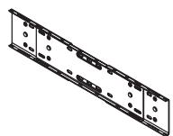
Wall Bracket
1
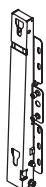
Hinge
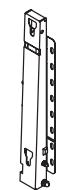
Left: 1
Right: 1

Accessories
Plastic Hanger: 4

Screw ⑥ :4

Screw@:11

Anchor : 11
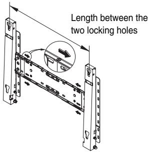
Wall Bracket Assembly
1 Insert and tighten the Captive Screw in the direction of the arrow. When done, mount the wall bracket on the wall.
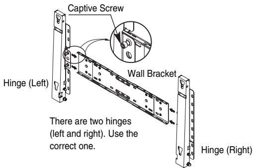
2 Before drilling into the wall, check if the length between the two locking holes at the back of the product is correct. If the length is too short or long, loosen all or some of the 4 screws on the wall bracket to adjust the length.
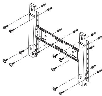
3 Check the installation diagram and mark the drill points on the wall. Use the 5.0mm bit to drill holes deeper than 35mm .
Fix each anchor in the corresponding hole.
Match each of the brackets and hinge holes to the corresponding anchor holes and insert and tighten the 11 screws ⑧
Continued...
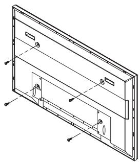
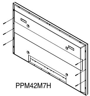
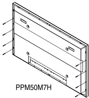
To mount the product on the wall bracket
The shape of the product may vary depending on the model. (The assemblies of the plastic hanger and the screw are the same)
1 Remove the 4 screws on the back of the product.
2 Insert the screw ⑥ into the plastic hanger. (See the figure below)
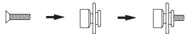

Mount the product on the wall bracket and make sure it is properly fixed to the left and right plastic hangers.
Be careful when installing the product on the bracket as fingers can be caught in the holes.
Make sure the wall bracket is securely fixed to the wall, or the product may not stay in place after installation.
3 Tighten the 4 screws in step 2 (plastic hanger + screw 包 ) to the rear holes of the product.
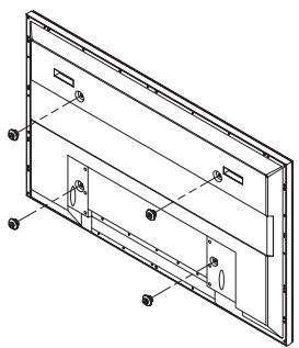
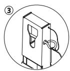
4 Remove safety pin (③) and insert the 4 product holders into the corresponding bracket holes (①). Then place the product (②) so that it is firmly fixed to the bracket. Make sure to reinsert and tighten the safety pin (③) to securely hold the product to the bracket.
PDP Display
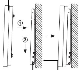
Wall Bracket Wall
Wall Bracket Angle Adjustment
Adjust the bracket angle to -2^ before installing it on the wall.
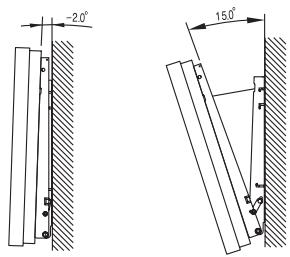
Fix the product to the wall bracket.
2 Hold the product at the top in the center and pull it forward (direction of the arrow) to adjust the angle. (See the figure to the right)
3 You can adjust the bracket angle between -2^ and 15^ .
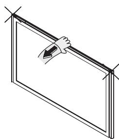
Make sure to use the top center, and not the left or the right side of the product to adjust the angle.
Installing the Display Vertically
- Samsung shall not be liable for damages caused by installing the product at the different direction from the figure below.
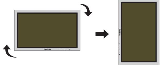
You can install the PDP Display vertically.
In this case, the fan automatically works.
If you wish to stop the fan, position the PDP Display horizontally and then set "Fan" to "Off" in the "Function" menu.
Please use the wall attachment panel exclusively when installing vertically. And you have to put the bottom of the PDP Display with menu buttons on the left when viewed from front.
Before Using the Video Wall and the Multiple Display Control function
1 Please create ID for each PDP Display before installing them close together. It may be difficult to create IDs when operating the remote control for PDPs that are installed close to each other.
2 For details about Video Wall configuration and operation, refer to "Setting the Multiple Screen" on page 32.
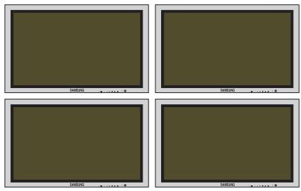
Example for 2x2 Video Wall function
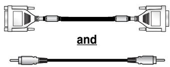
Example for 2x2 Video Wall connections
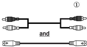
(1)

You can connect a Composite (Video) without a distributor as you would connect a PC.
Select ID input on the menu. Use the numeric buttons to enter the ID for PDP Display adjustment. You can operate the remote control only for the PDP Display that has been selected.
For details about Multiple Display Control, refer to "Setting the MDC (Multiple Display Control)" on page 28.
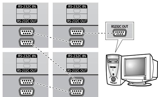
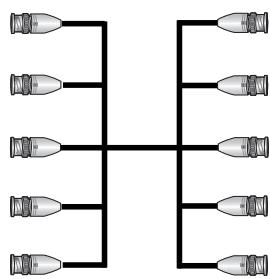
Example for Multiple Display Control connections
Connecting Speakers
Speakers are optional. You have to purchase the speakers additionally.
1 Remove the screws on the rear of the PDP Display.
2 Hang the two "T" shaped hangers on the square holes on the rear of the PDP Display.
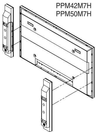
3 Tighten the PDP Display and the speaker bracket using the screws removed from the PDP Display.
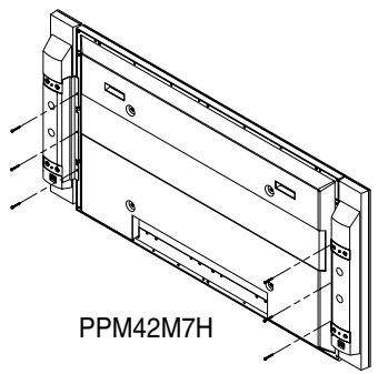
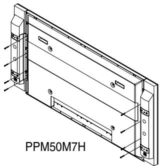
When moving your PDP Display, do NOT hold the speaker connected to your PDP Display. It may damage the bracket clamping the speaker and your PDP Display together and result in a drop of your PDP Display and a risk of personal damage and injury.
Continued...
Connect the speaker audio cable to the external speaker output jack on the rear of the PDP Display matching the "+" and "-" ends of the cable with the diagram on the PDP Display.
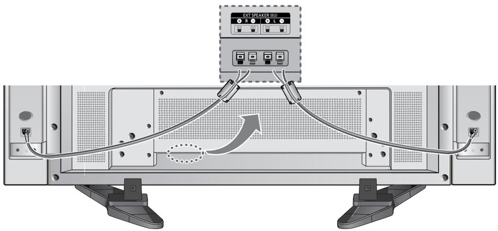

The speakers MUST have a power handling capability of 10 watts minimum (impedance 8 ).
When you connect the speaker wire to the external speaker out connector, first bind the speaker wire round the ferrite core to secure it.
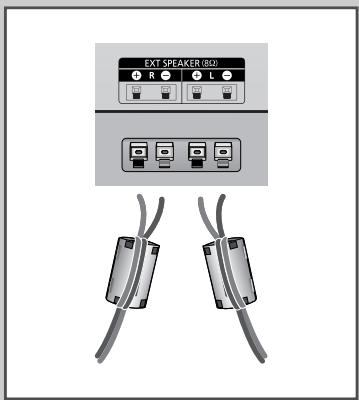
Ferrite Cores
The ferrite cores are used to attenuate undesired signals. When connecting cables, attach one of these ferrite cores to the cable near the connector.
Switching Your PDP Display On and Off
The mains lead is attached to the rear of your PDP Display.
1 Plug the mains lead into an appropriate socket.
Result: The Standby indicator on the front of the PDP Display lights up.

The main voltage is indicated on the rear of the PDP Display and the frequency is 50 or 60Hz
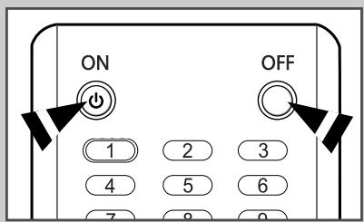
2
Press the “I/” button on the front of the PDP Display (or the ON (按钮 on the remote control) to switch the PDP Display on.
3
To switch your PDP Display off, press the "I/0" button again (or the OFF (◎) button on the remote control).
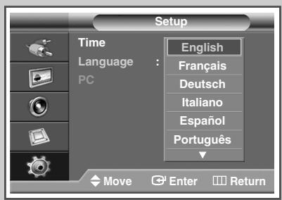
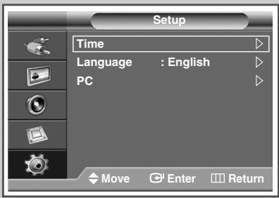
Choosing Your Language
When you start using your PDP Display for the first time, you must select the language which will be used for displaying menus and indications.
1 Press the MENU (□□) button.
Result: The main menu is displayed.
2 Press the or button to select Setup.
Result: The Setup menu is displayed.
3 Press the ENTER ( ) button.
4 Press the or button to select Language.
Press the ENTER ( +1 ) button.
Result: The available languages are listed.
5 Select the appropriate language by pressing the or button. Press the ENTER (按钮).
6 Press the EXIT button to exit.

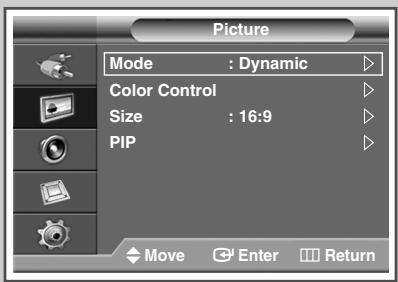
Changing the Picture Standard
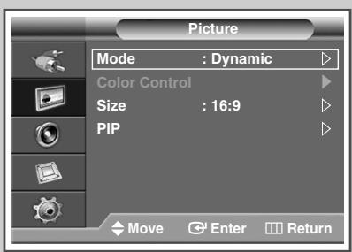
You can select the type of picture which best corresponds to your viewing requirements.
1 Press the MENU (□□) button.
Result: The main menu is displayed.
2 Press the or button to select Picture.
Result: The Picture menu is displayed.
3 Press the ENTER ( ) button.
Result: The Mode is selected.
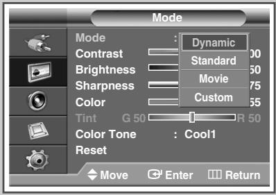
4 Press the ENTER ( l ) button again.
Result: The Mode menu is displayed.
5 Press the ENTER ( ) button.
Result: The following options are available.
Dynamic - Standard - Movie - Custom
6 Select the required option by pressing the or button.
7 Press the ENTER ( + ) button.
8 Press the EXIT button to exit.
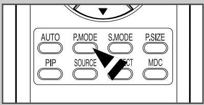
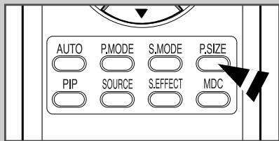
You can also set these options simply by pressing the P.MODE (Picture Mode) button on the remote control.
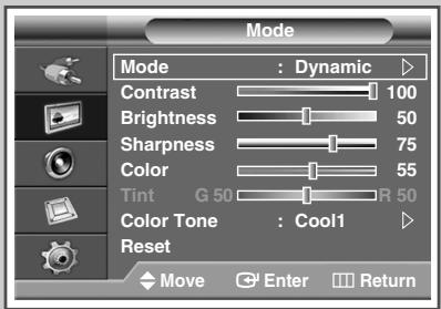
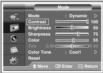
Customizing the Picture Settings
Your PDP Display has several setting options that allow you to control the picture quality.
1 Press the MENU (□□) button.
Result: The main menu is displayed.
2 Press the or button to select Picture.
Result: The Picture menu is displayed.
3 Press the ENTER (G) button.
Result: The Mode is selected.
4 Press the ENTER ( l ) button again.
Result: The Mode menu is displayed.
5 Press the ENTER ( + ) button.
Result: The following options are available.
Dynamic - Standard - Movie - Custom
6 Select the required option by pressing the or button.
7 Press the ENTER ( + ) button.
8 Select the required option by pressing the or button.
Result: The following options are available.
Contrast - Brightness - Sharpness - Color - Tint (NTSC only)
Contrast-Brightness-Color:PCorDVI Mode.
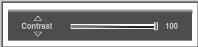
9 Press the ENTER (G) button.
Result: The horizontal bar is displayed.
Press the or button until you reach the optimal setting.
Press the or button to select other option(s).
The settings values may vary depending on the input source. (ex. AV, Component, PC, or DVI.)
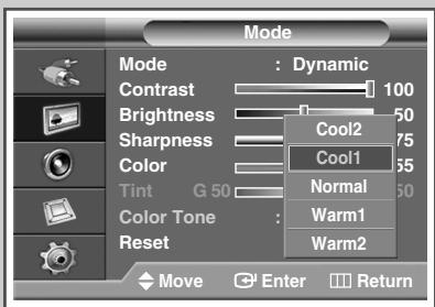
10 Press the MENU (□□) button to return to Mode menu.
Press the or button to select Color Tone.
Press the ENTER ( l ) button.
11 Select the required option by pressing the or button.
Result: The following options are available.
Cool2 - Cool1 - Normal - Warm1 - Warm2
12 Press the ENTER (G) button.
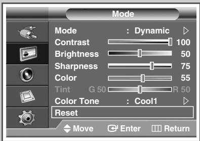
13 To return the factory defaults, select Reset by pressing the or button. Press the ENTER ( ( + - ) button.
Result: The previously adjusted settings will be reset to the factory defaults.
The reset function is set for each mode (Dynamic, Standard, Movie, or Custom).
The reset function is also set for each Color Tone (Cool2, Cool1, Normal, Warm1, or Warm2).
14 Press the EXIT button to exit.

Adjusting the RGB Color (PC Mode)
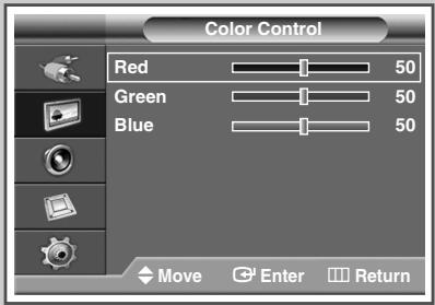
Preset to the PC mode by pressing the SOURCE button.
1 Press the MENU (□□) button.
Result: The main menu is displayed.
2 Press the or button to select Picture.
Result: The Picture menu is displayed.
3 Press the ENTER ( + ) button.
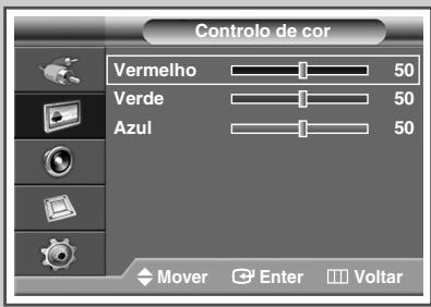
4 Press the or button to select Color Control. Press the ENTER ( + ) button.
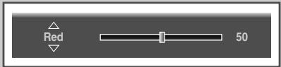
5 Select the required option (Red, Green, or Blue) by pressing the or button.
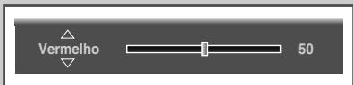
6 Press the ENTER ( l ) button.
Result: The horizontal bar is displayed.
Press the or button until you reach the optimal setting.
Press the or button to select other option(s).
7 Press the ENTER ( l ) button.
8 Press the EXIT button to exit.
Setting the Picture (PC Mode)
Preset to the PC mode by pressing the SOURCE button.
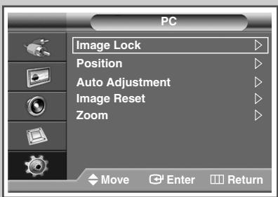
1 Press the MENU (□□) button.
Result: The main menu is displayed.
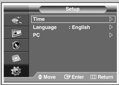
2 Press the or button to select Setup.
Result: The Setup menu is displayed.
3 Press the ENTER ( + ) button.
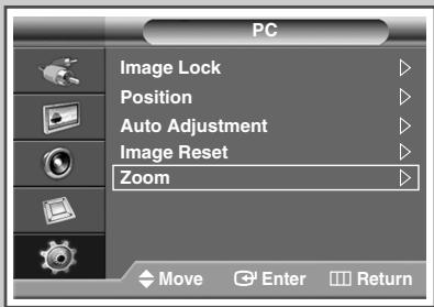
4 Press the or button to select PC. Press the ENTER (G) button.
Result: The PC menu is displayed.
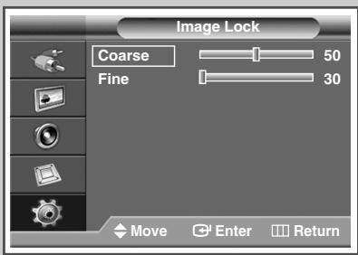
5 Press the ENTER ( l ) button to select Image Lock.
Continued...
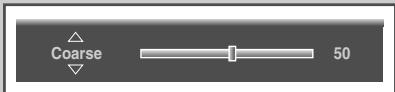
6 Press the or button to select the option (Coarse or Fine) to be adjusted. Press the ENTER () button.
Result: The horizontal bar is displayed. Press the or button until you reach the optimal setting.
Press the or button to select other option(s).
7 Press the ENTER ( l ) button.
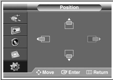
8 Press the MENU (□□) button.
Result: The PC menu is displayed again.
9 Press the or button to select Position. Press the ENTER (□) button.
10 Adjust the position by pressing the , , , or button.
11 Press the ENTER (G) button.
12 Press the or button to select Auto Adjustment. Press the ENTER ( ) button.
Result: The screen quality and position are automatically reset. The settings are all finished, and the PDP Display will automatically return to the previous picture.
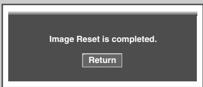
13 To return the factory defaults, select Image Reset by pressing the or button. Press the ENTER (按钮).
Result: The previously adjusted settings will be reset to the factory defaults.
14 Press the EXIT button to exit.

Using Zoom function (PC Mode)
Preset to the PC mode by pressing the SOURCE button.
1 Press the MENU (□□) button.
Result: The main menu is displayed.
2 Press the or button to select Setup.
Result: The Setup menu is displayed.
3 Press the ENTER ( ) button.
4 Press the or button to select PC. Press the ENTER ( + ) button.
Result: The PC menu is displayed.
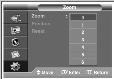
5 Press the or button to select Zoom. Press the ENTER ( ) button.
6 Press the ENTER (G) button again. Select the required option by pressing the or button.
Result: The following options are available.
$$ 0 - 1 - 2 - 3 - 4 - 5 - 6 $$
Option 0 represents a normal screen. The greater the number, the more magnified the screen.
You can select the position and reset functions by selecting options 1 through 6. (If you select option 0, the position and reset functions are not selected.)
If you have selected the Zoom function as between 1 6 you will not be able to select the Auto Adjustment function.
7 Press the ENTER (G) button.
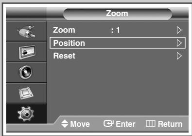
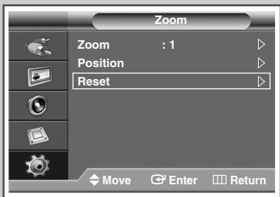
8 Press the or button to select Position. Press the ENTER ( ) button.
9 Adjust the position by pressing the , , or button.
10 Press the MENU (□□) button.
Result: The zoom menu is displayed again.
11 To return the factory defaults, select Reset by pressing the or button. Press the ENTER ( +1 ) button.
Result: The previously adjusted settings will be reset to the factory defaults.
12 Press the EXIT button to exit.
Selecting the Picture Size
You can select the picture size which best corresponds to your viewing requirements.
1 Press the MENU (□□) button.
Result: The main menu is displayed.
2 Press the or button to select Picture.
Result: The Picture menu is displayed.
3 Press the ENTER ( ) button.
4 Press the or button to select Size.
Press the ENTER (G) button.
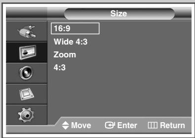
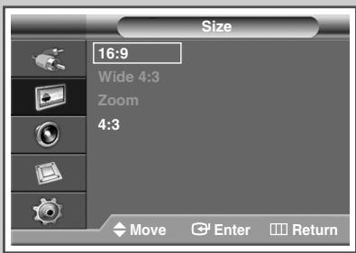
5 Select the required option by pressing the or button.
Result: The following options are available.
16:9 : Sets the picture to 16:9 wide mode.
Wide 4:3 : Magnify the size of the picture more than 4:3.
Move the screen up/down using the or button after selecting the by pressing the or ENTER (□) button.
Zoom : Magnify the size of the picture vertically on screen.
4:3 Sets the picture to 4:3 normal mode.
6 Press the ENTER ( ) button.
7 Press the EXIT button to exit.

You can select these options simply by pressing the P.SIZE button on the remote control.
If you change the picture size when PIP is On, PIP will automatically be turned Off.
Depending on the input source, the P.SIZE options may vary.
PC and DVI modes, only 16:9 & 4:3 modes can be selected.
Positioning and Sizing the screen using Zoom

Resizing the screen using the Zoom enables the positioning and sizing of the screen to up/down direction using the or button as well as the screen size.
Move the screen up/down using the or button after selecting the by pressing the or button.
Resize the screen vertically using the or button after selecting the by pressing the or button.
(Pressing the button extends it upward and pressing the
button extends it downward.)
Screen enlargement operates only in Video/S-Video/ Component input modes.
PC/DVI modes prevent the screen enlargement function.

PC to DVI Mode
Freezing the Current Picture
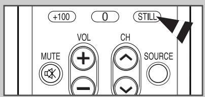
You can freeze the picture when watching a moving picture simply by pressing the " STILL" button. To return to normal viewing, press it again.
In PIP mode, Still function will be applied to the main and sub picture at the same time.
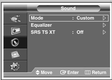
Changing the Sound Standard
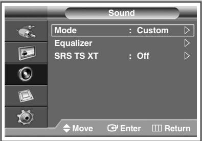
You can select the type of special sound effect to be used when watching a given broadcast.
1 Press the MENU (□□) button.
Result: The main menu is displayed.
2 Press the or button to select Sound.
Result: The Sound menu is displayed.
3 Press the ENTER ( + ) button.
Result: The Mode is selected.
4 Press the ENTER ( l ) button again.
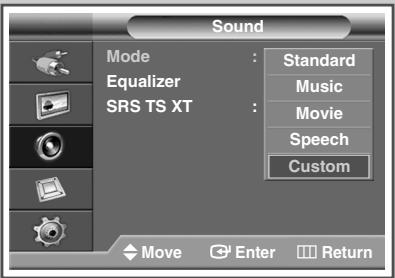
Select the required option by pressing the or button.
Result: The following options are available.
Standard - Music - Movie - Speech - Custom
5 Press the ENTER ( + ) button.
6 Press the EXIT button to exit.
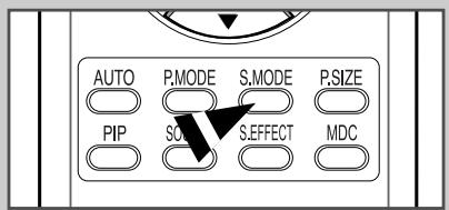
You can select these options by simply pressing the S.MODE (Sound Mode) button on the remote control.
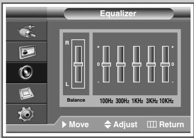
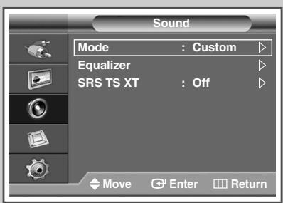
Customizing the Sound Settings
Your PDP Display has several settings which allow you to control the sound quality.
1 Press the MENU (□□) button.
Result: The main menu is displayed.
2 Press the or button to select Sound.
Result: The Sound menu is displayed.
3 Press the ENTER (G) button.
4 Press the or button to select Equalizer. Press the ENTER (G) button.
Result: The Equalizer menu is displayed.
5 Select the required option (balance or equalizer) by pressing the or button.
6 Press the or button until you reach the optimal setting. Press the ENTER ( l ) button.
7 Press the EXIT button to exit.
Setting the TruSurround XT
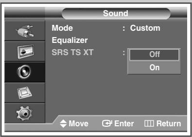
TruSurround XT is a patented SRS technology that solves the problem of playing 5.1 multichannel content over two speakers. TruSurround delivers a compelling, virtual surround sound experience through any two-speaker playback system, including internal PDP Display speakers. It is fully compatible with all multichannel formats.
1 Press the MENU (□□) button.
Result: The main menu is displayed.
2 Press the or button to select Sound.
Result: The Sound menu is displayed.
3 Press the ENTER ( + ) button.
4 Press the or button to select SRS TS XT. Press the ENTER (G) button.
5 Select off or on by pressing the or button. Press the ENTER ( +1 ) button.
6 Press the EXIT button to exit.
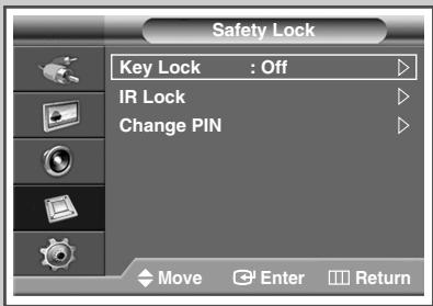
Activating Panel Button Lock
This feature allows you to lock the PDP Display panel buttons so that it cannot be operated via the PDP Display panel. It can, however, still be operated via the remote control. Only remote control can release the panel lock setting, so keep the remote control away from unauthorized users.
1 Press the MENU (□□) button.
Result: The main menu is displayed.
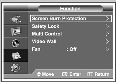
2 Press the or button to select Function.
Result: The Function menu is displayed.
3 Press the ENTER ( + ) button.
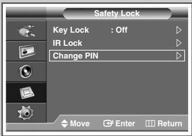
4 Press the or button to select Safety Lock. Press the ENTER (G) button.
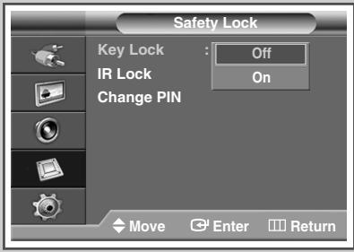
5 Press the ENTER ( l ) button again to select Key Lock.
6 Select off or on by pressing the or button. Press the ENTER (G) button.
7 Press the EXIT button to exit.

Activating Remote Control Button Lock

This feature allows you to lock the remote control so that it cannot be operated via the remote control. It can, however, still be operated via the PDP Display Panel buttons.
1 Press the MENU (□□) button.
Result: The main menu is displayed.
2 Press the or button to select Function.
Result: The Function menu is displayed.
3 Press the ENTER (G) button.
4 Press the or button to select Safety Lock. Press the ENTER (按钮).
5 Press the or button to select IR Lock. Press the ENTER (G) button.
6 Press the EXIT button to exit.
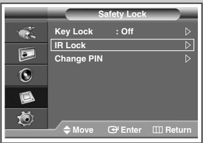
IR Lock: On
When IR Lock is set to On, you will not be able to use the remote control even if the remote control button is pressed. To unlock the Remote Control Button Lock, enter the PIN using the numeric keys on the remote control.
'IR LOCK : OFF' will appear. The default PIN is "0000". You can set the PIN in the "Change PIN" menu.
Setting Up Your Personal ID Number
This feature sets viewing restrictions and prevents unauthorized access to your PDP Display through the PIN (Personal Identification Number), which is a 4 digit number.
1 Press the MENU (□□) button.
Result: The main menu is displayed.
2 Press the or button to select Function.
Result: The Function menu is displayed.
3 Press the ENTER ( + ) button.
4 Press the or button to select Safety Lock. Press the ENTER ( ) button.
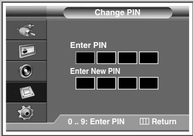
5 Press the or button to select Change PIN. Press the ENTER ( + ) button.
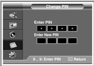
6 Press the number buttons to enter your current 4-digit pin number. The default pin number for a new PDP Display set is "0000".
7 Press the numeric buttons to enter your new 4-digit pin number. Re-enter your new pin number to confirm.
8 Press the EXIT button to exit.
If you forget the pin number, press the remote control buttons in the following sequence, which resets the pin to 0-0-0-0: MUTE, 1, 8, 6.

Setting the MDC (Multiple Display Control)
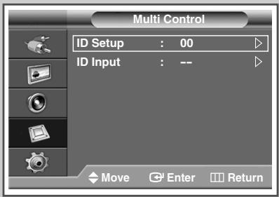
This function enables you to easily control the connected PDP Displays on the PC by specifying IDs to connected PDP Displays.
1 Press the MENU (□□) button.
Result: The main menu is displayed.
2 Press the or button to select Function.
Result: The Function menu is displayed.
3 Press the ENTER ( + ) button.
4 Press the or button to select Multi Control.
5 Press the ENTER (G) button.
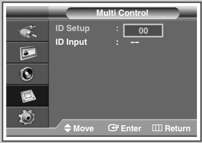
Result: The Multi Control menu is displayed with the ID Setup selected.
6 Press the ENTER ( + ) button again.
Select the ID setup number by using the numeric buttons. Press the ENTER ( l ) button.
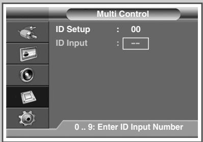
7 Press the or button to select ID Input.
Press the ENTER (G) button.
8 Enter ID input number by using the numeric buttons.
9 Press the EXIT button to exit.
To operate the multi control function, PDP1 and PDP2 should be set in the ID Setup mode. When entering the ID Input number of PDP1 while the PDP Display is set in the ID Input mode, only PDP1 is switched to the Menu screen and you can operate the remote control. At this time, PDP2 doesn't operate with the remote control and displays the standby mode of ID Input.
For further details, refer to the MDC program guide.
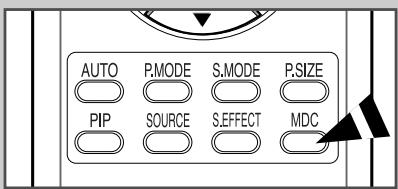
You can select these options by simply pressing the MDC (Multiple Display Control) button on the remote control.
Refer to the following Web site for information about MDC programs and protocol documents: http://www.samsung.com/support/productsupport/download/index.aspx
Preventing Screen Burn-in
To reduce the possibility of screen burn, this unit is equipped with screen burn prevention technology. This technology enables you to set picture movement up/down (Vertical Line) and side to side (Horizontal Dot). The Time setting allows you to program the time between movement of the picture in minutes.
1 Press the MENU (□□) button.
Result: The main menu is displayed.
2 Press the or button to select Function.
Result: The Function menu is displayed.
3 Press the ENTER ( ) button.
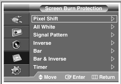
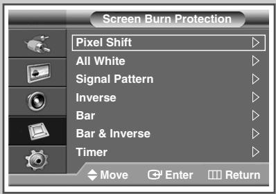
4 Press the or button to select Screen Burn Protection. Press the ENTER (G) button.
Result: The Screen Burn Protection menu is displayed with the Pixel Shift selected.
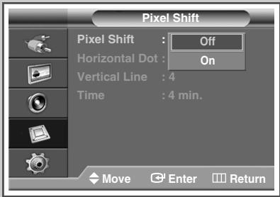
5 Press the ENTER (G) button again.
Result: The Pixel Shift menu is selected.
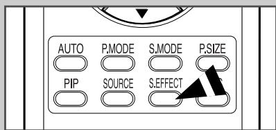
You can select these options by simply pressing the S.EFFECT button on the remote control.
6 Press the ENTER ( ) button.
Select on by pressing the or button for making the screen move per regular hour and preventing the residual image. Press the ENTER (按钮).
Pixel Shift: Using this function, you can minutely move pixels on the PDP in horizontal or vertical direction to prevent after image on the screen.
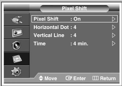
7 Select the required option (Horizontal Dot, Vertical Line, or Time) by pressing the or button. Press the ENTER ( + ) button.
8 Press the or button until you reach the optimal setting. Press the ENTER ( ) button.
Optimum condition for pixel shift;
| PPM42M7H | PPM50M7H | |
| Horizontal Dot | 2 | 4 |
| Vertical Line | 4 | 4 |
| Time | 4 min. | 4 min. |
9 Press the EXIT button to exit.

Reducing the Effects of Screen Burn

If screen burn has occurred, you can select a white screen or inverse function to help remove screen burn artifacts.
1 Press the MENU (□□) button.
Result: The main menu is displayed.
2 Press the or button to select Function.
Result: The Function menu is displayed.
3 Press the ENTER (G) button.
4 Press the or button to select Screen Burn Protection. Press the ENTER (G) button.
Result: The Screen Burn Protection menu is displayed with the Pixel Shift selected.
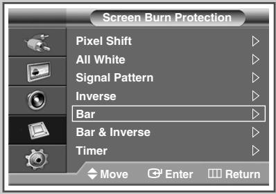
5 Press the or button to select the option (All White, Signal Pattern, Inverse, Bar or Bar & Inverse). Press the ENTER (G) button.
All White: This function removes after images on the screen by changing the color of pixels to white. Use this function when there are remaining after images or symbols on the screen especially when you displayed a still image on the screen for a long time.
Signal Pattern: This function removes after images on the screen by moving all the pixels on the PDP Display according to a pattern. Use this function when there are remaining after images or symbols on the screen especially when you displayed a still image on the screen for a long time.
Inverse: This function removes after images on the screen when the PDP Display is remained on for prolonged periods by converting RGB input signal into GBR. Compared to All White and Signal Pattern function, this function can reduce burn in when you watch PDP Display. Using the inverse function when you watch PDP Display can cause the color reversal on the screen. (ex. The colors in red line can be shown as the colors in green line on the screen.)
Bar: This function removes after images on the screen when the PDP Display is remained on for prolonged periods by crossing the vertical white bar from left to right. Compared to All White and Signal Pattern function, this function can reduce burn in when you watch PDP Display. Using the bar mode function when you watch PDP Display can cause poor picture quality with the vertical white bar appeared on some parts of the screen.
Bar & Inverse: This function removes after images on the screen when the PDP Display is remained on for prolonged periods by converting RGB input signal into GBR and crossing the vertical white bar from left to right. Compared to All White and Signal Pattern function, this function can reduce burn in when you watch PDP Display. Using the inverse function when you watch PDP Display can cause the color reversal on the screen. (ex. The colors in red line can be shown as the colors in green line on the screen.)
6 Press the ENTER ( + ) button.
To remove after images on the screen, use either All White, Signal Pattern, Inverse, Bar or Bar & Inverse function. Although both of the four functions remove after images on the screen, "Signal Pattern" is more effective.
The after image removal function has to be executed for a long time (approximately 1 hour) to effectively remove after images on the screen. If after image is not removed after the execution of the function, repeat the function additionally.
Setting the Screen Burn Protection Timer
You can set the timer for Screen Burn Protection (hours, minutes). If you start the operation to erase any residual image, the operation will be performed for the set period of time and then automatically finish.
1 Press the MENU (□□) button.
Result: The main menu is displayed.
2 Press the or button to select Function.
Result: The Function menu is displayed.
3 Press the ENTER ( + ) button.
4 Press the or button to select Screen Burn Protection. Press the ENTER ( + ) button.
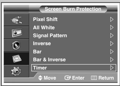
5 Press the or button to select Timer. Press the ENTER ( ) button.
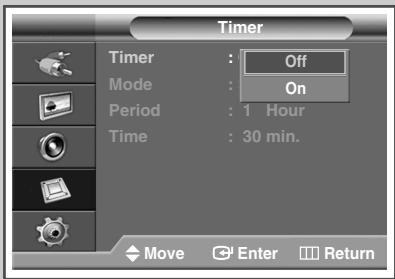
Result: The Timer menu is displayed.
6 Press the ENTER ( l ) button again.
7 Select on by pressing the or button. Press the ENTER (按钮) button.
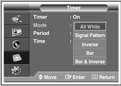
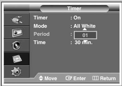
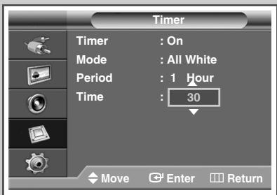
8 Select the required option by pressing the or button.
Result: The following options are available.
Mode : All White, Signal Pattern, Inverse, Bar, Bar & Inverse
Period : Hour(1~24)
Time :Minute(1-30)
9 Press the EXIT button to exit.
Setting the Multiple Screen

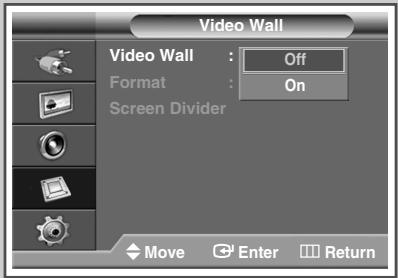
You can get various display effects with many PDPs.
1 Press the MENU (□□) button.
Result: The main menu is displayed.
2 Press the or button to select Function.
Result: The Function menu is displayed.
3 Press the ENTER (G) button.
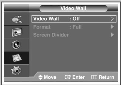
4 Press the or button to select Video Wall.
5 Press the ENTER (G) button.
Result: The Video Wall menu is displayed with the Video Wall selected.
6 Press the ENTER (G) button.
Select on by pressing the or button.
Press the ENTER (G) button.
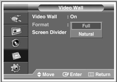
7 Press the or button to select Format.
Press the ENTER ( ) button.
8 Select the required option by pressing the or button.
Result: The following options are available.

Full: This option displays divided images on multiple PDP Displays without missing parts as if only the viewable part of the separate PDP Displays were simply part of a large single PDP Display.
Natural: This option displays divided images on multiple PDP Displays as if the separate PDP Displays were simply part of a large single PDP Display. Therefore there are missing parts on the edge of the PDP Displays.
Press the ENTER (G) button.
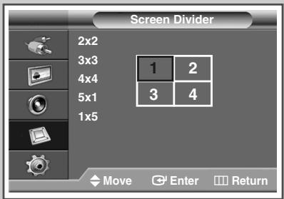
9 Press the or button to select Screen Divider.
Press the ENTER (G) button.
10 Select the option (2x2, 3x3, 4x4, 5x1, or 1x5) by pressing the
or button. Press the ENTER ( ) button.
11 Press the or button to select the position of the screens.
12 Press the EXIT button to exit.
The PIP function and Picture Size do not work during the Video Wall operation.
The VESA Format input does not support the Video Wall function in DVI mode.
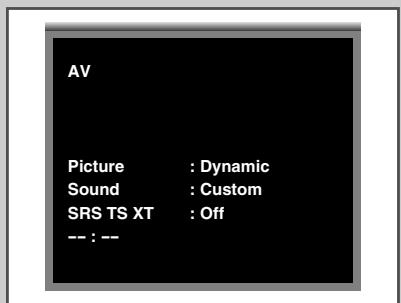
Displaying the Setting Information
You can view the setting status you select by pressing the "INFO" button on the remote control.
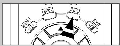
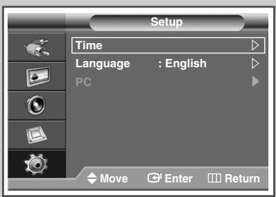
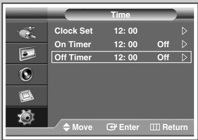
Setting and Displaying the Current Time
You can set the PDP Display's clock so that the current time is displayed by pressing the "INFO" button. You must also set the time if you wish to use the automatic on or off timers.
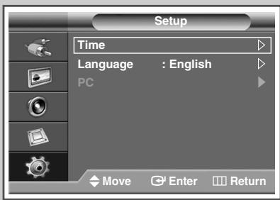
1 Press the MENU (□□) button.
Result: The main menu is displayed.
2 Press the
or button to select Setup.
Result: The Setup menu is displayed.
3 Press the ENTER ( + ) button.
4 Press the
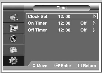
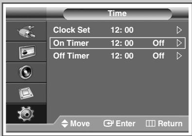
or button to select Time.
Press the ENTER ( l ) button.
Result: The Clock Set is selected.
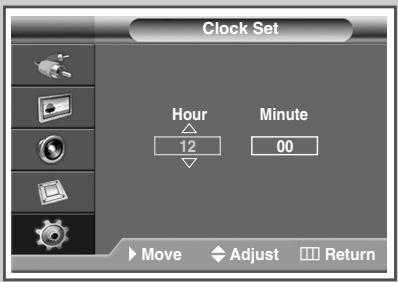
5 Press the ENTER (G) button again.
6 Press the or button to select Hour or Minute.
Set these by pressing the or button.
You can set the hour and minute directly by pressing the numeric buttons on the remote control.
7 Press the ENTER (G) button.
8 Press the EXIT button to exit.
In the event of a power interruption or the set being turned off at the supply, the settings for the Clock will be lost.
English-33
Switching the PDP Display On and Off Automatically

You can set the on or off timers so that the PDP Display will:
Switch on automatically and tune source of your choice at the time you select.
Switch off automatically at the time you select.
The first step is to set the PDP Display's clock (refer to "Setting and Displaying the Current Time" on page 33).
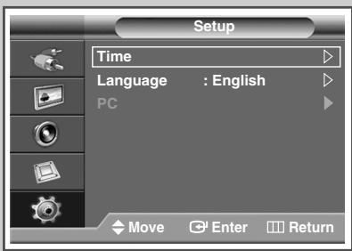
1 Press the MENU (□□) button.
Result: The main menu is displayed.
2 Press the or button to select Setup.
Result: The Setup menu is displayed.
3 Press the ENTER ( + ) button.
4 Press the or button to select Time. Press the ENTER (□) button.
Result: The Time menu is displayed.
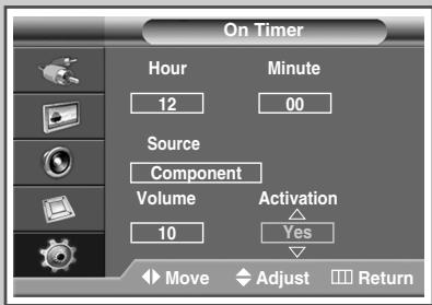
5 Press the or button to select On Timer. Press the ENTER ( +1 ) button.
Result: The On Timer menu is displayed.
6 Select Hour, Minute, Source (AV, S-Video, Component, PC1, PC2, or DVI), or Volume by pressing the or button. Set these by pressing the or button.
You can set the hour and minute directly by pressing the numeric buttons on the remote control.
7 Press the or button to select Activation.
8 To activate On Timer with the setting entered, select Yes by pressing the or button.
9 Press the ENTER (G) button.
Result: The Time menu is displayed again.
Continued...
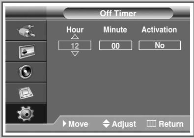
10 Press the or button to select Off Timer.
Press the ENTER (G) button.
Result: The Off Timer menu is displayed.
11 Select Hour or Minute by pressing the or button.
Set these by pressing the or button.
You can set the hour and minute directly by pressing the numeric buttons on the remote control.
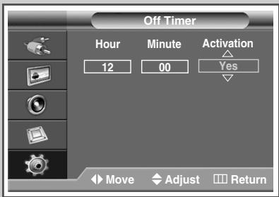
12 Press the or button to select Activation.
13 To activate Off Timer with the setting entered, select Yes by pressing the or button.
14 Press the ENTER (G) button.
15 Press the EXIT button to exit.
Auto Power Off
When you set the timer "On", the PDP Display will eventually turn off, if no controls are operated for 3 hours after the PDP Display was turned on by timer. This function is only available in timer "On" mode and prevents overheating, which may occur if a PDP Display is on for too long.
Selecting the Fan
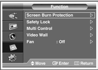
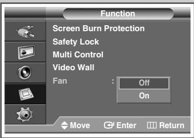
Fans inside the PDP Display are used to lower the temperature of the tops and the front of the PDP Display. To reduce the noise of the fan, you may stop the fan by setting the Fan to "Off".
The temperature of the top and the front of the PDP Display may increase when you watch the PDP Display for a long period of time while the fan is stopped, but the PDP Display will operate normally.
1 Press the MENU (□□) button.
Result: The main menu is displayed.
2 Press the or button to select Function.
Result: The Function menu is displayed.
3 Press the ENTER ( + ) button.
4 Press the or button to select Fan. Press the ENTER ( ) button.
5 Select off or on by pressing the or button. Press the ENTER ( ) button.
6 Press the EXIT button to exit.
If your PDP Display is displayed vertically, the fan automatically works.
The message Check Fan is displayed if there is a fan problem.
Please use the fan when the temperature is over 35 degrees.
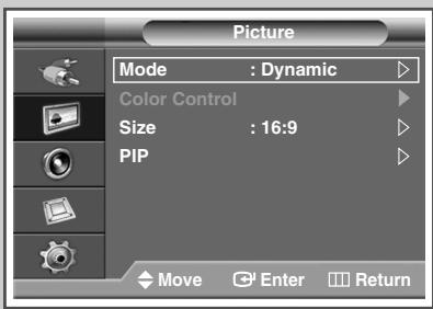
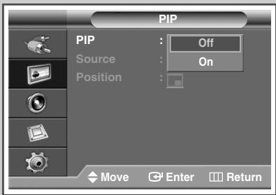
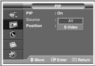
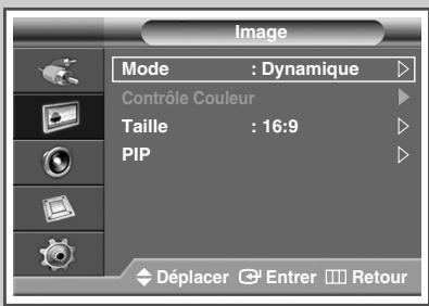
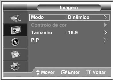
Viewing the Picture in Picture (PIP)
You can display a sub picture within the main picture of external A/V devices. In this way you can PDP Display the video input from any connected devices while monitoring other video inputs.
1 Press the MENU (□□) button.
Result: The main menu is displayed.
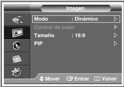
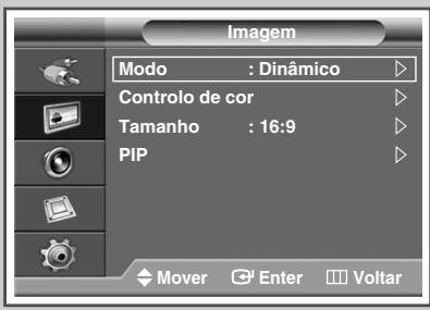
2 Press the or button to select Picture.
Result: The Picture menu is displayed.
3 Press the ENTER ( ) button.
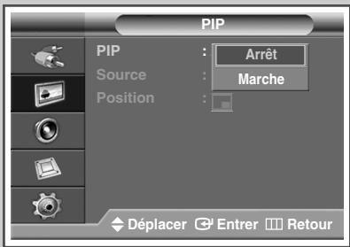
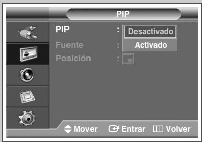
4 Press the or button to select PIP. Press the ENTER ( +1 ) button.
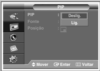
Result: The PIP is selected.
5 Press the ENTER (G) button again. To activate, set PIP to On by pressing the or button. Press the ENTER (G) button.
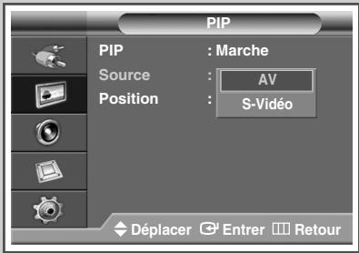
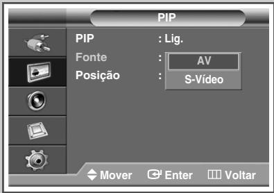
6 Press the or button to select Source. Press the ENTER ( ) button.
Result: The following options are available.
AV-S-Video
7 Select a source of the sub picture by pressing the or button. Press the ENTER (G) button.
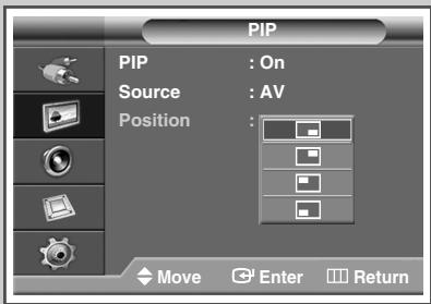
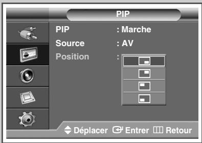
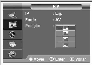
8 Press the or button to select Position. Press the ENTER ( ) button.
Result: The following options are available.
9 Select a position of the sub picture by pressing the or button. Press the ENTER (G) button.
10 Press the EXIT button to exit.
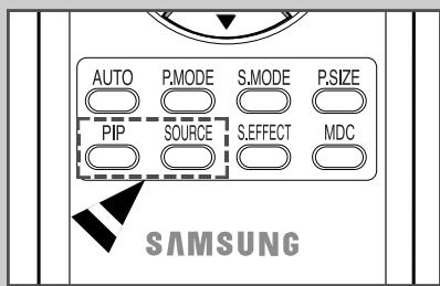
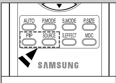
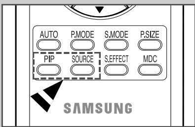
Easy functions of the remote control.
Buttons Feature
PIP Used to activate or deactivate the PIP function directly.
SOURCE Used to assign a source of the sub picture (AV, S-Video).
Table of PIP Settings
X - This PIP combination is not available.
O - This PIP combination is available.
| Main Sub | AV(CVBS) | S-Video | Component | PC1 | PC2 | DVI |
| AV(CVBS) | X | X | X | X | X | X |
| S-Video | X | X | X | X | X | X |
| Component | X | X | X | X | X | X |
| PC1 | O | X | X | X | X | X |
| PC2 | O | X | X | X | X | X |
| DVI | O | O | X | X | X | X |

Viewing an External Signal Source
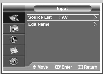
Once you have connected up your various audio and video systems, you can view different sources by selecting the appropriate input.
1 Press the MENU (□□) button.
Result: The main menu is displayed.
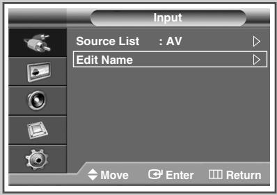
2 Press the or button to select Input.
Result: The Input menu is displayed.
3 Press the ENTER (G) button.
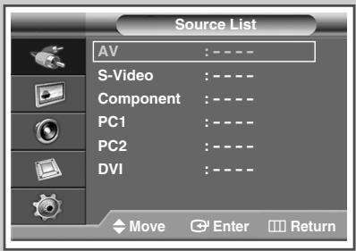
Result: The Source List is selected.
4 Press the ENTER (G) button again.
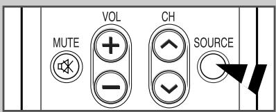
5 Press the or button to select the signal source, press the ENTER (G) button.
Result: The available signal sources are listed.
AV, S-Video, Component, PC1, PC2, or DVI
You can also set these options simply by pressing the SOURCE button on the remote control.
6 Repeat steps 1 to 3.
Result: The Input menu is displayed again.
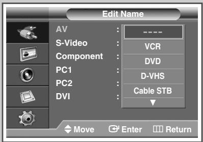
7 Press the or button to select Edit Name.
Press the ENTER (G) button.
8 Press the or button to select external source to be edited. Press the ENTER (G) button.
Result: The available device names are listed.
VCR, DVD, D-VHS, Cable STB, HD STB, Satellite STB, AV Receiver, DVD Receiver, Game, Camcorder, DVD Combo, DHR (DVD HDD Recorder), or PC
9 Select the required device by pressing the or button.
Press the ENTER (G) button.
10 Press the EXIT button to exit.
If you change the external source while viewing, it might take a short period of time for picture to be switched.
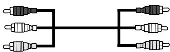
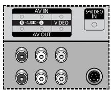
Connecting to the Audio/Video Input
The "AV IN" connectors are used for the equipment with an Composite Video output, such as video game devices or video disc players.
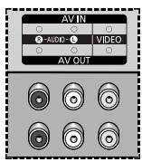
Rear of the PDP Display
(Input)
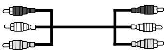
The "AV OUT" connectors are used for the equipment with an Composite Video input, such as a camcorder or VCR.
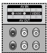
Rear of the PDP Display
(Output)
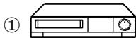
VCR
DVD
Decoder / Video game device
Video disc player

Camcorder
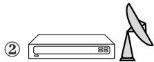
Satellite receiver
① If you have a second VCR and wish to copy cassettes tape, connect the source VCR to “AV IN” and the target VCR to “AV OUT” so that you can redirect the signal from “AV IN” to “AV OUT”.
② When you wish to record a programme, connect the receiver to "AV IN" and the VCR to "AV OUT" so that you can redirect the signal from "AV IN" to "AV OUT".
Signal is outputted through the AV OUT only when the signal source is AV.

Whenever you connect an audio or video system to your PDP Display, ensure that all elements are switched off.
Refer to the documentation supplied with your equipment for detailed connection instructions and associated safety precautions.
Connecting to the S-Video Input
The S-VIDEO and RCA (AUDIO-L/R) connectors are used for equipment with an S-Video output, such as a camcorder or VCR.
Rear of the PDP Display

Camcorder
VCR
① To play picture and sound, both the S-VIDEO and RCA connectors must be used.
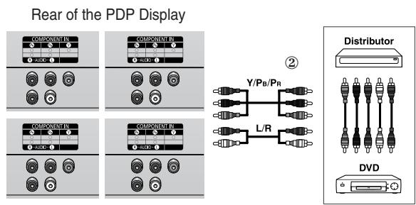
Connecting to the Component Input
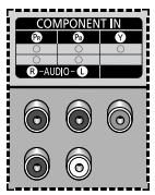
Rear of the PDP Display
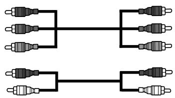
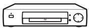
DVD
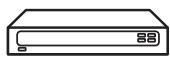
DTV Receiver
The COMPONENT IN connectors are used for DTV receiver or DVD.
(480i,p/576i,p/720p/1080i)
Connecting to the DVD/DTV Receiver Input
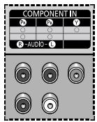
Rear of the PDP Display
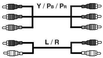
The "COMPONENT IN" (or "Y/ P_B / P_R " (video) and "AUDIO") connectors are used for equipment with a DVD/ DTV Receiver output. (480i, 576i, 480p, 576p, 720p, 1080i)
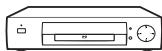
DVD
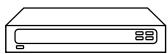
Digital Set-Top Box
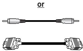
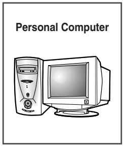
Connecting to the DVI Input
The "DVI IN" (video) and "AUDIO" connectors are used for equipment with a DVI output.
Rear of the PDP Display
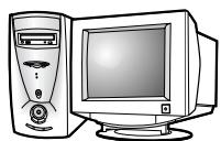
Personal Computer
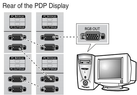
Connecting to the PC Input
The "PC 1" (or "PC IN2 (BNC)") and "AUDIO" connectors are used for interfacing with your PC.
Rear of the PDP Display
Only when watching PDP Display in PC1 mode, you can use the RGB OUT port to connect the current screen to another PDP in the same mode.
Setting up Your PC Software (Windows only)
The Windows display-settings for a typical computer are shown below. But the actual screens on your PC will probably be different, depending upon your particular version of Windows and your particular video card. But even if your actual screens look different, the same, basic set-up information will apply in almost all cases. (If not, contact your computer manufacturer or Samsung Dealer.)
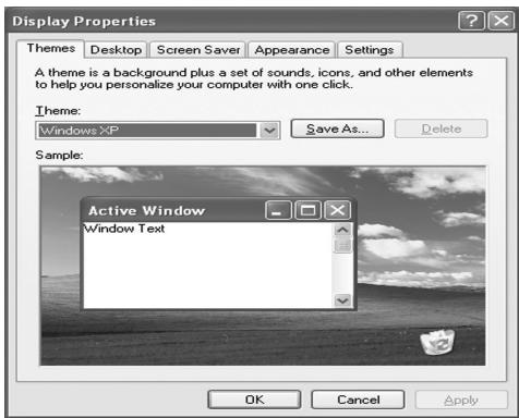


1 Right click the mouse on the Windows Desktop, then click on Properties.
The Display Properties will be displayed.
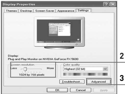
2 Click on Settings tab, then set the Display Mode with reference to the Display Modes Table. You do not need to change the Colours settings.
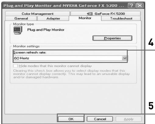
3 Click on Advanced. A new settings dialog box will be displayed.
4 Click on the Monitor tab, then set the Screen refresh rate with reference to the Display Modes Table. Set the Vertical Frequency and Horizontal Frequency individually if you can do so instead of setting the Screen refresh rate.
5 Click on OK to close the window, then Click on OK button to the Display Properties window.
Automatic re-booting may commence at this moment.
6 Shutdown the PC, and connect it to your PDP Display. ("Connecting to the PC Input" on page 42)

The actual screens on your PC may look different, depending on your particular version of Windows and the type of your PC.
When you use your PDP Display as a PC monitor, it supports Colours up to 32 bits.
In this case, the display on the PDP Display may look different depending on your particular version of Windows or the PC manufacturer.
When connecting a PC (including the DVI connection), you must set it to the display settings that are supported by the PDP Display. Otherwise, the message Out of input range will be displayed.
Input Mode (PC/DVI)
Both screen position and size will vary depending on the type of PC monitor and its resolution. The table below shows all of the display modes that are supported:
| Resolution | Vertical frequency (Hz) | Horizontal frequency (kHz) | PPM42M7H | PPM50M7H | |
| VGA | 640 x 350 | 70 | 31.5 | ✓ | ✓ |
| 85 | 37.9 | ✓ | ✓ | ||
| 720 x 400 | 70 | 31.5 | ✓ | ✓ | |
| 85 | 37.9 | ✓ | ✓ | ||
| 640 x 480 | 60 | 31.5 | ✓/◎ | ✓/◎ | |
| 72 | 37.9 | ✓ | ✓ | ||
| 75 | 37.5 | ✓ | ✓ | ||
| 85 | 43.3 | ✓ | ✓ | ||
| SVGA | 800 x 600 | 56 | 35.2 | ✓ | ✓ |
| 60 | 37.9 | ✓/◎ | ✓/◎ | ||
| 72 | 48.1 | ✓ | ✓ | ||
| 75 | 46.9 | ✓ | ✓ | ||
| 85 | 53.7 | ✓ | ✓ | ||
| XGA | 1024 x 768 | 60 | 48.4 | ✓ | ✓ |
| 70 | 56.5 | ✓ | ✓ | ||
| 75 | 60.0 | ✓/◎ | ✓/◎ | ||
| *85 | 68.7 | ✓ | ✓ | ||
| WVGA | 848 x 480 | 60 | 29.8 | *✓ | *✓ |
| 72 | 35.1 | *✓ | *✓ | ||
| 75 | 36.0 | *✓ | *✓ | ||
| *85 | 37.0 | ✓ | ✓ | ||
| *852 x 480 | 60 | 31.8 | |||
| *1152 x 864 | 75 | 67.5 | ✓ | ✓ | |
| SXGA | *1280 x 1024 | 60 | 64.0 | ✓/◎ | ✓/◎ |
| 75 | 80.0 | ✓ | ✓ | ||
| WXGA | *1280 x 768 | 60 | 47.7 | ✓ | ✓ |
| 75 | 60.1 | ✓ | ✓/◎ | ||
| 1360 x 768 | 60 | 47.8 | ✓/◎ | ||
| UXGA | *1600 x 1200 | 60 | 75.0 | ✓ | ✓ |
"mode does not work with DVI mode.
The interlace mode is not supported.
The PDP might operate abnormally if a non-standard video format is selected.
The 852 x 480 mode is only supported by a particular video card (PIXEL PERFECT made by IMAGINE GRAPHICS Ltd.).
In 1360× 768 resolution, the screen displays 1360 pixels horizontally.
A "mark means that this mode can be supported.
A “ ” mark means that this mode is recommended. The picture may be blurred when the resolution is not a recommended resolution.
In DVI mode, this product does not support DDC in DTV format (1080i/720p/480p); some of DVD/STBs supporting DTV format may display the poor picture.

PPM42M7H/50M7H
ENERGY STAR
Power Saver (PC1 mode only)
This PDP Display has a built-in power management system called Power Saver. This power management system saves energy by switching your PDP Display into a low-power mode when it has not been used for a certain amount of time. You use a software utility installed on your computer to set up this feature. See the table below for details.
| State | Normal Operation | Power-saving Function Mode | |
| Suspend Mode Position A1 | Power-off Mode Position A2 | ||
| Horizontal Sync | Active | Active | Inactive |
| Vertical Sync | Active | Inactive | Inactive |
| Video | Active | Blanked | Blanked |
| Power Indicator | Green On | Green Blinking (3 sec Interval) | Green Blinking (3 sec Interval) |
If the horizontal sync is inactive and the vertical sync active, this PDP Display goes to the screen mute state.
This PDP Display automatically returns to normal operation when horizontal and vertical sync return.
This occurs when moving the computer's mouse or pressing a key on the keyboard.
For energy conservation, turn your PDP Display OFF when it is not needed, or when leaving it unattended for long periods.
Troubleshooting: Before Contacting Service Personnel
Before contacting Samsung after-sales service, perform the following simple checks.
If you cannot solve the problem using the instructions below, note the model and serial number of the PDP Display and contact your local dealer.
| No sound or picture | ◆ Check that the mains lead has been connected to a wall socket. ◆ Check that you have pressed the ON or OFF button on the remote control. ◆ Check the picture contrast and brightness settings. ◆ Check the volume. |
| Normal picture but no sound | ◆ Check the volume. ◆ Check whether the volume MUTE button on the remote control has been pressed. |
| No picture or black and white picture | ◆ Adjust the color settings. ◆ Check that the video system selected is correct. |
| Sound and picture interference | ◆ Plug your PDP Display into a different mains socket. |
| Remote control malfunctions | ◆ Replace the remote control batteries. ◆ Clean the upper edge of the remote control (transmission window). ◆ Check the battery terminals. |
| Screen is black and power indicator light blinks steadily. | ◆ On your computer check: Power, Signal Cable. The PDP Display is using its power management system. Move the computer's mouse or press any key on the keyboard. |
Technical Specifications
| Dimensions (W x D x H) | PPM42M7H - 1027 x 96.5 x 630.5 mm ; 40.43 x 3.79 x 24.82 inches PPM50M7H - 1204 x 96.6 x 724.1 mm ; 47.4 x 3.8 x 28.5 inches |
| Weight (Without stand) | PPM42M7H - 35.0 kg PPM50M7H - 41.0 kg |
| Screen aspect ratio | 16:9 |
| Screen size | PPM42M7H - 42 inch PPM50M7H - 50 inch |
| Native pixel resolution (H x V) | PPM42M7H - 1024 x 768 PPM50M7H - 1366 x 768 |
| Color systems | PAL, SECAM, NTSC (NT3.58/NT4.43) |
| Sound | Stereo, SRS TSXT |
| Audio output power | 10W + 10W (8Ω) |
| Video inputs | VIDEO IN - AV/S-VIDEO COMPONENT IN - Y/PB/PR (RCA, 3P, 480i~1080i) RGB1(PC1) IN - D-SUB, 15P RGB2(PC2) IN VGA~UXGA (R/G/B/H/V) DVI IN - DVI-D type |
| PDP Display outputs | VIDEO OUT - VIDEO/L/R (RCA, 3P) |
| Audio inputs | VIDEO IN - L/R COMPONENT IN - L/R (RCA, 2P) AUDIO (Stereo jack for RGB1/2(PC1/2) and DVI input, 2 x mini jack) |
| Audio outputs | EXT SPEAKER (8Ω) - R+/-, L+/- |
| External control | RS232C - IN/OUT (D-SUB, 9P) |
This device is a Class B digital apparatus.
Design and specifications are subject to change without prior notice.
For the power supply and Power Consumption, refer to the label attached to the product.
This page is intentionally left blank.
This page is intentionally left blank.
SAMSUNG
SAMSUNG
Ensemble de support mural
| Principale | Secondaire | AV(CVBS) | S-Viséo | Composant | PC1 | PC2 | DVI |
| AV(CVBS) | X | X | X | X | X | X | X |
| S-Viséo | X | X | X | X | X | X | X |
| Composant | X | X | X | X | X | X | X |
| PC1 | O | X | X | X | X | X | X |
| PC2 | O | X | X | X | X | X | X |
| DVI | O | O | X | X | X | X | X |
(480i,p/576i,p/720p/1080i).
Specifications techniques
| Dimensions (larg. x prof. x haut.) | PPM42M7H - 1027 x 96.5 x 630.5 mm; 40.43 x 3.79 x 24.82 pouces PPM50M7H - 1204 x 96.6 x 724.1 mm; 47.4 x 3.8 x 28.5 pouces |
| Poids (sans support) | PPM42M7H - 35.0 kg PPM50M7H - 41.0 kg |
| Format de l'image | 16:9 |
| Dimension de l'écran | PPM42M7H - 42 po PPM50M7H - 50 po |
| Résolution standard (H x V) | PPM42M7H - 1024 x 768 PPM50M7H - 1366 x 768 |
| Systèmes couleurs | PAL, SECAM, NTSC (NT3.58/NT4.43) |
| Son | Stéroy, SRS TSXT |
| Puisance de sortie audio | 10W + 10W (8Ω) |
| Entrées video | VIDEO IN - AV/S-VIDEO COMPONENT IN - Y/PB/PR (RCA, 3P, 480i~1080i) RGB1(PC1) IN - D-SUB, 15P RGB2(PC2) IN - VGA~UXGA (R/G/B/H/V) DVI IN - DVI-D type |
| Sorties écran | VIDEO OUT - VIDEO/L/R (RCA, 3P) |
| Entrées audio | VIDEO IN - L/R COMPONENT IN - L/R (RCA, 2P) AUDIO (prise stéroy pour RGB1/2(PC1/2) et entrée DVI, 2 x prise miniature) |
| Sorties audio | EXT SPEAKER (8Ω) - R+/-, L+/- |
| Commande externe | RS232C - IN/OUT (D-SUB, 9P) |
Pantalla PDP professional (PANTALLA DE PLASMA)
PPM42M7H
PPM50M7H
| Sub Principal | AV(CVBS) | S-Video | Componente | PC1 | PC2 | DVI |
| AV(CVBS) | X | X | X | X | X | X |
| S-Video | X | X | X | X | X | X |
| Componente | X | X | X | X | X | X |
| PC1 | O | X | X | X | X | X |
| PC2 | O | X | X | X | X | X |
| DVI | O | O | X | X | X | X |


(480i,p/576i,p/720p/1080i)
Tela PDP Professional (PLASMA DISPLAY PANEL)
PPM42M7H
PPM50M7H
Manual do Usuário
MDC (Multiple Display Control)
Como colocar as pilhas no controle remoto
1 Plug the mains lead into an appropriate socket.
Resultado: A luz indicadora Standby na parte frontal da Tela PDP se acende.
Como ajustar as cores RGB (Modo PC)
| Sub Principal | AV (CVBS) | S-Video | Componente | PC1 | PC2 | DVI |
| AV (CVBS) | X | X | X | X | X | X |
| S-Video | X | X | X | X | X | X |
| Componente | X | X | X | X | X | X |
| PC1 | O | X | X | X | X | X |
| PC2 | O | X | X | X | X | X |
| DVI | O | O | X | X | X | X |
6 Repita as etapas 1 a 3.
(480i,p/576i,p/720p/1080i)
Como conectar a entrada de DVD/DTV Receiver
| Resolução | Frequência vertical (Hz) | Frequência horizontal (kHz) | PPM42M7H | PPM50M7H | |
| VGA | 640 x 350 | 70 | 31.5 | ✓ | ✓ |
| 85 | 37.9 | ✓ | ✓ | ||
| 720 x 400 | 70 | 31.5 | ✓ | ✓ | |
| 85 | 37.9 | ✓ | ✓ | ||
| 640 x 480 | 60 | 31.5 | ✓/② | ✓/② | |
| 72 | 37.9 | ✓ | ✓ | ||
| 75 | 37.5 | ✓ | ✓ | ||
| 85 | 43.3 | ✓ | ✓ | ||
| SVGA | 800 x 600 | 56 | 35.2 | ✓ | ✓ |
| 60 | 37.9 | ✓/② | ✓/② | ||
| 72 | 48.1 | ✓ | ✓ | ||
| 75 | 46.9 | ✓ | ✓ | ||
| 85 | 53.7 | ✓ | ✓ | ||
| XGA | 1024 x 768 | 60 | 48.4 | ✓ | ✓ |
| 70 | 56.5 | ✓ | ✓ | ||
| 75 | 60.0 | ✓/② | ✓/② | ||
| *85 | 68.7 | ✓ | ✓ | ||
| WVGA | 848 x 480 | 60 | 29.8 | *✓ | *✓ |
| 72 | 35.1 | *✓ | *✓ | ||
| 75 | 36.0 | *✓ | *✓ | ||
| *85 | 37.0 | ✓ | ✓ | ||
| *852 x 480 | 60 | 31.8 | |||
| *1152 x 864 | 75 | 67.5 | ✓ | ✓ | |
| SXGA | *1280 x 1024 | 60 | 64.0 | ✓/② | ✓/② |
| 75 | 80.0 | ✓ | ✓ | ||
| WXGA | *1280 x 768 | 60 | 47.7 | ✓ | ✓ |
| 75 | 60.1 | ✓ | ✓/② | ||
| 1360 x 768 | 60 | 47.8 | ✓/② | ||
| UXGA | *1600 x 1200 | 60 | 75.0 | ✓ | ✓ |