
KFVD16K - Basket ELECTROLUX - Free user manual and instructions
Find the device manual for free KFVD16K ELECTROLUX in PDF.
| Brand | ELECTROLUX |
| Model | KFVD16K |
| Product type | Cooker hood |
| Control | Touch |
| Motor speeds | 3 speeds + timed maximum speed (8 min) |
| Lighting | LED, independent control |
| Hob2Hood function | Automatic, infrared communication with hob |
| Filter notification | Yes, for grease filter and charcoal filter |
| Grease filter | Dishwasher safe (short cycle, low temperature) |
| Charcoal filter | Non-washable, replace every 4 to 6 months |
| Filter maintenance | Monthly cleaning of grease filter, replacement of charcoal filter according to notification |
| Bulb | LED, replacement only by a technician |
| Safety | Clean regularly to prevent grease buildup and fire risk |
| Recycling | Appliance and accessories recyclable, do not dispose of with household waste |
Frequently Asked Questions - KFVD16K ELECTROLUX
User questions about KFVD16K ELECTROLUX
0 question about this device. Answer the ones you know or ask your own.
Ask a new question about this device
Download the instructions for your Basket in PDF format for free! Find your manual KFVD16K - ELECTROLUX and take your electronic device back in hand. On this page are published all the documents necessary for the use of your device. KFVD16K by ELECTROLUX.
USER MANUAL KFVD16K ELECTROLUX
natural_image
Technical line drawing of a mechanical component with two labeled parts (1 and 2), showing internal structure and rotation arrows (no text or symbols beyond labels)natural_image
Technical line drawing of a mechanical component with two labeled parts (1 and 2), showing internal structure and rotation arrows (no text or symbols beyond labels)natural_image
Technical line drawing of a mechanical component with two labeled parts (1 and 2), showing internal structure and rotation arrows (no text or symbols beyond labels)natural_image
Technical line drawing of a mechanical component with two labeled parts (1 and 2), showing internal structure and rotation arrows (no text or symbols beyond labels)WE'RE THINKING OF YOU
Thank you for purchasing an Electrolux appliance. You've chosen a product that brings with it decades of professional experience and innovation. Ingenious and stylish, it has been designed with you in mind. So whenever you use it, you can be safe in the knowledge that you'll get great results every time.
Welcome to Electrolux.
Visit our website to:

Get usage advice, brochures, trouble shooter, service and repair information: www.electrolux.com/support

Register your product for better service: www.registerelectrolux.com

Buy Accessories, Consumables and Original spare parts for your appliance: www.electrolux.com/shop
CUSTOMER CARE AND SERVICE
Always use original spare parts.
When contacting our Authorised Service Centre, ensure that you have the following data available: Model, PNC, Serial Number.
The information can be found on the rating plate.
⚠ Warning / Caution-Safety information
i General information and tips
Environmental information
Subject to change without notice.
1. SAFETY INFORMATION AND INSTALLATION

WARNING!
Refer to the separate Installation Instructions booklet for Safety Information and Installation. Read carefully the Safety chapters before any use or maintenance of the appliance.
2. PRODUCT DESCRIPTION
2.1 Control panel overview
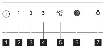
| Function | Description | |
| 1 | On / Off | Turns the hood on and off. |
| 2 | First speed | The motor switches to first speed level. |
| 3 | Second speed | The motor switches to second speed level. |
| 4 | Third speed | The motor switches to third speed level. |
| 5 | Maximum speed | The motor switches to maximum speed. |
| 6 | Filter notification | Reminds to change or clean the charcoal filter and clean the grease filter. |
| 7 | Lamp | Turns the lights on and off. |
3. DAILY USE
3.1 Using the hood
Check the recommended speed according to the table below.
| 1 | While heating up food, cooking with covered pots. |
| 2 | While cooking with covered pots on multiple cooking zones or burners, gentle frying. |
| 3 | While boiling and frying big quantities of food without a lid, cooking on multiple cooking zones or burners. |
| While boiling and frying big quantities of food without a lid, big humidity. |

It is recommended to leave the hood operating for approximately 15 minutes after cooking.

The control Panel is a sensor field. Touch the symbols for 1 second to activate the functions.
To operate the hood:
- Turn on the appliance by pressing the Ⓐ symbol.
You can now activate the functions.
- To activate the function touch the symbol.

The hoods light works independently to other hood functions. To illuminate the cooking surface touch 🙏️.
To turn off the appliance press the Ⓘ symbol again.
3.2 Hob ^2 Hood function
It is an automatic function which connects the hob with a hood. Both the hob and the hood have an infrared signal communicator. Speed of the fan is defined automatically on basis of mode setting and temperature of the hottest cookware on the hob. You can also operate the fan using the hob manually. The function can be activated from panel of the hob.


For more information how to use the function refer to the hob user manual.
3.3 Activating Maximum Motor Speed
When you touch 🚙, the Maximum Motor Speed starts to operate for 8 minutes. After that time, the appliance returns to its previous speed settings.
4. CARE AND CLEANING
4.1 Notes on cleaning

Cleaning Agents

When the function is turned on, additional touch on 🌿 does not have any effects.
3.4 Filter notification
Filter alarm reminds to change or clean the charcoal filter and clean the grease filter. The filter indicator is turned on for 30 seconds if the grease filter must be cleaned. The filter indicator flashes for 30 seconds if the charcoal filter must be replaced or cleaned.

Refer to cleaning the grease filter in care and cleaning chapter.

Refer to cleaning the charcoal filter or replacing the charcoal filter in care and cleaning chapter.
To reset the function touch ⚙ for 3 seconds.
To activate or deactivate function:
- Switch on the control panel. Make sure that the panel is on.
- To activate function touch 🎨 for 3 seconds.
If the function is activated, the filter icon flashes five times. - To deactivate function touch 🎨 for 3 seconds.
If the function is deactivated, the filter icon ☒ turns on for 4 seconds.
Do not use abrasive detergents and brushes.
Clean the surface of the appliance with a soft cloth with warm water and a mild detergent.
After cooking some parts of appliance can get hot. To avoid stains appliance must be cooled down and dried with clean cloth or paper towels.
Clean stains with a mild detergent.

Keep the hood clean
Clean the appliance and grease filters each month. Clean the interior and grease filters carefully from fat. Fat accumulation or other residue may cause fire. Follow the instructions for cleaning the accessories when filter notification is on. Refer to Filter notification in daily use chapter.
Grease filters can be washed in a dishwasher.
The dishwasher must be set to a low temperature and a short cycle. The grease filter may discolour, it has no influence on the performance of the appliance.
Charcoal filter
The time of saturation of the charcoal filter varies depending on the type of cooking and the regularity of cleaning the grease filter. The activated charcoal filter is not washable, cannot be regenerated and must be replaced approximately every 4/6 months of operation, or more frequently for particularly heavy usage.
4.2 Cleaning the grease filter
Filters are mounted with the use of clips and pins on the opposite side.
To clean the filter:
- Press the handle of the mounting clip on the filter panel underneath the hood (1).
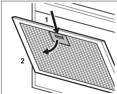
- Slightly tilt the front of the filter downwards (2), then pull.
Repeat the first two steps for all filters. - Clean the filters using a sponge with non abrasive detergents or in a dishwasher.

The dishwasher must be set to a low temperature and a short cycle. The grease filter may discolour, it has no influence on the performance of the appliance.
- To mount the filters back follow the first two steps in reverse order.
Repeat the steps for all filters if applicable.
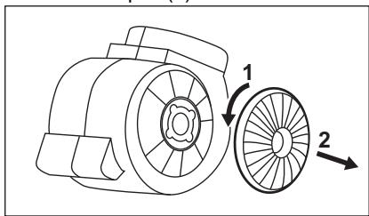
4.3 Replacing the charcoal filter
The charcoal filter must be replaced if the filter alarm is on.

Refer to the filter notification in daily use chapter for more information about function.

WARNING!
The charcoal filter is NON-washable! The filter cannot be regenerated!
To replace the charcoal filter:
- Remove the grease filters from the appliance.
Refer to "Cleaning the grease filter" in this chapter. - Turn the filter counterclockwise (1) and then pull (2).
natural_image
Technical line drawing of a mechanical component with two labeled parts (1 and 2), showing internal structure and rotation arrows (no text or symbols beyond labels)To mount the filters back follow the steps in reverse order.
In any case, it is necessary to replace the filters at least every four months.
4.4 Replacing the lamp
This appliance is supplied with a LED lamp and separate control gear (LED
driver). These parts can be replaced by a technician only. In case of any malfunction refer to "Service" in the "Safety Instructions" chapter.
5. ENVIRONMENTAL CONCERNS
Recycle materials with the symbol 📋. Put the packaging in relevant containers to recycle it. Help protect the environment and human health by recycling waste of electrical and electronic appliances. Do not dispose of
appliances marked with the symbol 📄 with the household waste. Return the product to your local recycling facility or contact your municipal office.
CONTENIDO
natural_image
Technical line drawing of a mechanical component with two labeled parts (1 and 2), showing internal structure without any text or symbols.natural_image
Technical line drawing of a mechanical component with two labeled parts (1 and 2), showing internal structure without any text or symbols.5. JÄÄTMEKÄITLUS
natural_image
Technical line drawing of a mechanical component with two labeled parts (1 and 2), showing internal structure and rotation arrows (no text or symbols beyond labels)3. SVAKODNEVNA UPORABA
3.1 Uporaba nape
natural_image
Technical line drawing of a mechanical component with two labeled parts (1 and 2), showing internal structure and rotation arrows (no text or symbols beyond labels)natural_image
Technical line drawing of a mechanical component with two labeled parts (1 and 2), showing internal structure and rotation arrows (no text or symbols beyond labels)natural_image
Technical line drawing of a mechanical component with two labeled parts (1 and 2), showing internal structure and rotation arrows (no text or symbols beyond labels)natural_image
Technical line drawing of a mechanical component with two labeled parts (1 and 2), showing internal structure without any text or symbols.natural_image
Technical line drawing of a mechanical component with two labeled parts (1 and 2), showing internal structure without any text or symbols.5. APLINKOS APSAUGA
natural_image
Technical line drawing of a mechanical component with two labeled parts (1 and 2), showing internal structure without any text or symbols.natural_image
Technical line drawing of a mechanical component with two labeled parts (1 and 2), showing internal structure without any text or symbols.5. MILIEUBESCHERMING
natural_image
Technical line drawing of a mechanical component with two labeled parts (1 and 2), showing internal structure and rotation arrows (no text or symbols beyond labels)natural_image
Technical line drawing of a mechanical component with two labeled parts (1 and 2), showing internal structure and rotation arrows (no text or symbols beyond labels)natural_image
Technical line drawing of a mechanical component with two labeled parts (1 and 2), showing internal structure without any text or symbols.natural_image
Technical line drawing of a mechanical component with two labeled parts (1 and 2), showing internal structure and rotation arrows (no text or symbols beyond labels)5. SKRB ZA OKOLJE
2. PËRSHKRIM I PRODUKTIT
natural_image
Technical line drawing of a mechanical component with two labeled parts (1 and 2), showing internal structure and rotation arrows (no text or symbols beyond labels)natural_image
Technical line drawing of a mechanical component with two labeled parts (1 and 2), showing internal structure and rotation arrows (no text or symbols beyond labels)reparationsinformation:
www.electrolux.com/support