
HTS9CBK3X - Tumble drier HOOVER - Free user manual and instructions
Find the device manual for free HTS9CBK3X HOOVER in PDF.
| Product type | Extractor hood |
| Brand | Hoover |
| Model | HTS9CBK3X |
| Dimensions (W x D x H) | 90 x 50 x 65-75 cm (estimated) |
| Weight | Approximately 15 kg (estimated) |
| Power supply | 220-240 V ~ 50 Hz, fuse 3A |
| Energy efficiency class | A (estimated) |
| Extraction speeds | 3 speeds + booster function (5 min) |
| Control | Push buttons or keys depending on version (5 possible configurations) |
| Lighting | Integrated LED, max 1.5W |
| Grease filter | Metal, dishwasher safe, monthly cleaning recommended |
| Activated carbon filter | Optional for recirculation mode, annual replacement |
| Exhaust duct diameter | 150 mm |
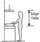
| Minimum distance above cooking surface | 65-75 cm for electric/gas hobs |
| Timer | Yes, adjustable up to 60 minutes (depending on version) |
| Display | LCD on some versions (time, timer, speed) |
| Noise level | Approximately 55-65 dB(A) depending on speed (estimated) |
| Installation modes | External exhaust or recirculation |
| Protection | Class I, earthing mandatory |
| Maintenance | Exterior cleaning with soft cloth; monthly cleaning of grease filter; annual replacement of carbon filter |
| Safety | Do not flambé under hood; adequate ventilation; supervise children |
| Spare parts | Filters, LED bulb, motor, controls (available from after-sales service) |
| Warranty | 2 years (standard, depending on country) |
Frequently Asked Questions - HTS9CBK3X HOOVER
User questions about HTS9CBK3X HOOVER
0 question about this device. Answer the ones you know or ask your own.
Ask a new question about this device
Download the instructions for your Tumble drier in PDF format for free! Find your manual HTS9CBK3X - HOOVER and take your electronic device back in hand. On this page are published all the documents necessary for the use of your device. HTS9CBK3X by HOOVER.
USER MANUAL HTS9CBK3X HOOVER
natural_image
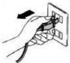
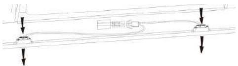
Diagram of airflow around a mechanical component with directional arrows indicating movement (no text or symbols)- Prije ugradnje, isključite uređaj i odspojite iz električne mreže.

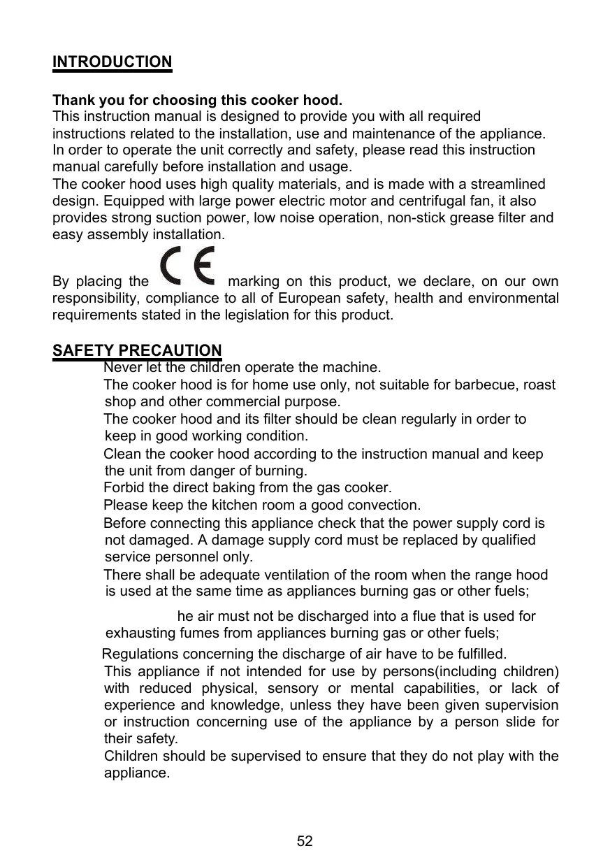
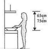
- Za najbolji radni učinak, kuhinjska napa treba biti postavljena na visini 65 \~75 cm iznad štednjaka/ploče za kuhanje.
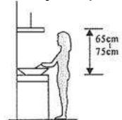
Za nagnuti panel model
- potrebno izbušiti 2x8mm dodatne rupe i pričvrsne vijke i zaporne vijke prije ugradnje
natural_image
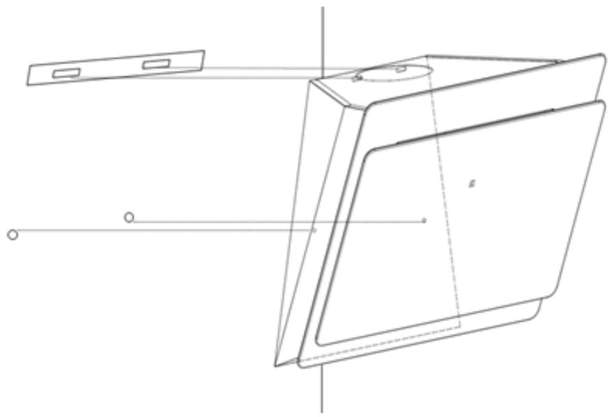
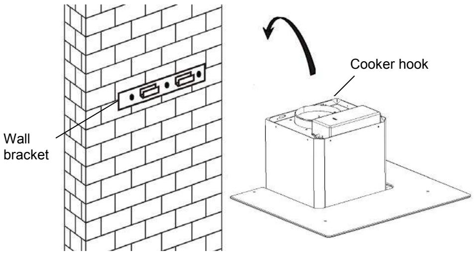
Technical line drawing of a mechanical component with mounting holes and a central circular feature (no text or symbols)- Podignite napu i objesite je na zidni nosač pomoću kuke.
natural_image
Diagram of a brick wall with a container and a small object inserted, no text or symbols presentnatural_image
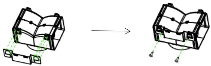
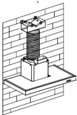
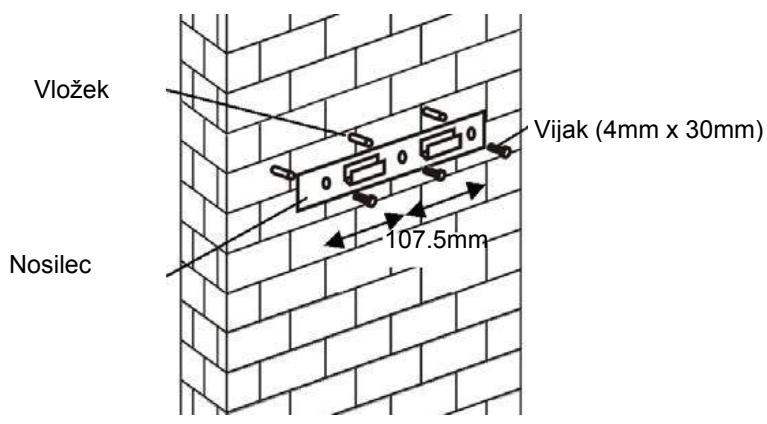
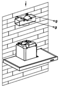
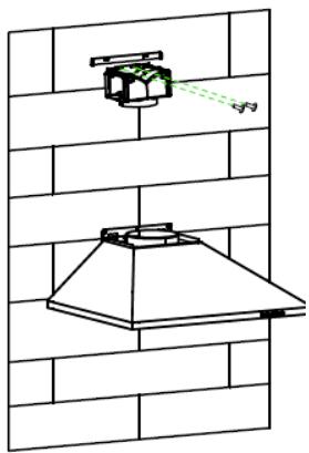
Technical line drawing of two mechanical components with mounting brackets and fasteners (no text or symbols)- Izbušite 2 rupe za postavljanje zidnih utikača, zatim zavijte i pričvrstite nosač na zid pomoću isporučenih vijaka 2 kom ST4x30mm.

natural_image
Technical line drawing of a brick wall with two components, one mounted on a platform and the other above (no text or symbols)natural_image
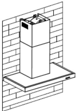
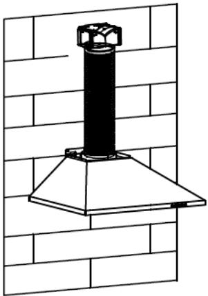
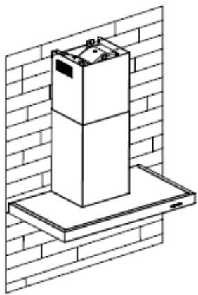
Technical line drawing of a mechanical assembly mounted on a brick wall (no text or symbols)- Ugradite dimnjak na jedinicu i popravite ga.
natural_image
Isometric line drawing of a cabinet mounted on a brick wall (no text or symbols)natural_image
Diagram showing a mechanical assembly before and after transformation, with no visible text or symbols.natural_image
Technical diagram showing a mounted device mounted on a platform against a brick wall, with no visible text or symbols.natural_image
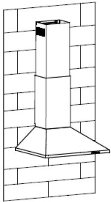
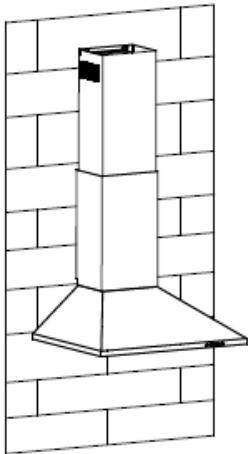
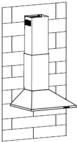
Technical line drawing of a chimney mounted on a base, against a brick wall background (no text or symbols)- Ugradite dimnjak na jedinicu i popravite ga.
natural_image
Line drawing of a chimney mounted on a brick wall (no text or symbols)natural_image
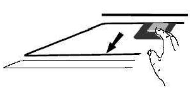
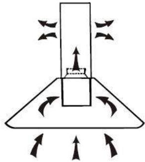
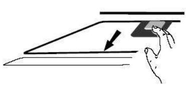
Diagram of a mechanical or fluid system with directional arrows indicating flow or movement (no text or symbols)Pri unutarnjoj ventilaciji, za filtriranje dima i para koristi se aktivni ugljeni filter. Prije ugradnje aktivnog ugljenog filtera, prvo uklonite filter za masnoću. Pritisnite zasun i povucite filter prema dole.
natural_image
Simple line drawing of a hand pressing down on a flat surface with a downward arrow (no text or symbols)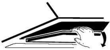
natural_image
Simple line drawing of a hand pressing down on a laptop keyboard (no text or symbols)natural_image
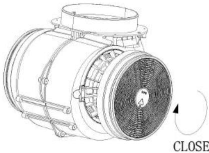
Technical line drawing of an electric motor with visible blades and mounting flanges (no text or symbols)CLOSE ZATVARANJE
VAŽNA NAPOMENA:
o Budite sigurni da je aktivni ugljeni filter sigurno i ispravno učvršćen. U suprotnom se može olabaviti i izazvati opasnost.
o Sa ugrađenim aktivnim ugljenim filterom, usisna snaga kuhinjske biti će manja.
KONFIGURACIJA 1
1
2
3

RADNE TIPKE
Dugme 1
natural_image
Pure electrical circuit lines without any symbolsnatural_image
Diagram of a mechanical or fluidic system with directional arrows indicating flow or movement (no text or symbols present)natural_image
Diagram of a brick wall with a metal bracket and directional arrows indicating movement or force (no text or symbols)Šroub 4x30 mm
Pro modely se šikmouplochou
natural_image
Technical line drawing of a 3D rectangular panel with mounting holes and internal structure, no text or symbols presentnatural_image
Diagram showing a brick wall with electrical outlets and a ceiling-mounted device, no text or symbols present.natural_image
Diagram of a brick wall with a box and a small object inside, no text or symbols presentnatural_image
Technical line drawing of a mechanical assembly with mounting brackets (no text or symbols)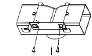
natural_image
Pure mechanical assembly diagram without any text, numbers, or symbolsnatural_image
Technical line drawing of a brick wall assembly with two components, no text or symbols presentnatural_image
Technical line drawing of a mechanical assembly mounted on a brick wall (no text or symbols)natural_image
Isometric line drawing of a multi-tiered storage unit mounted on a shelf against a brick wall (no text or symbols)natural_image
Technical line drawing of a mechanical component with green dashed alignment lines (no text or symbols)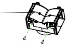
natural_image
Pure mechanical component diagram without any text, numbers, or symbolsnatural_image
Technical line drawing of a mechanical device mounted on a brick wall, with no visible text or symbols.natural_image
Technical line drawing of a chimney mounted on a brick wall (no text or symbols)natural_image
Line drawing of a double-hopper kitchen chimney mounted on a brick wall (no text or symbols)natural_image
Diagram of a mechanical or fluid system with directional arrows and a central block, no text or symbols present.natural_image
Simple line drawing of a hand pressing down on a flat surface with an arrow indicating downward motion (no text or symbols)
natural_image
Simple line drawing of a hand pressing down on a laptop keyboard (no text or symbols)natural_image
Technical line drawing of a mechanical component with no visible text or symbolsPoznámka:
natural_image
Pure electrical circuit lines without any symbolsINSTALLATION AND USER'S MANUAL
CONTENT
INTRODUCTION 52
SAFETY PRECAUTION 52
SPECIFICATION 55
INSTALLATION (VENT OUTSIDE) 56
INSTALLATION (VENT INSIDE) 67
DESCRIPTION OF COMPONENTS 68
OPERATION 68
MAINTENANCE 73
TROBULESHOOTING 74
CONFORMITY WITH DIRECTIVES 74
ENVIRONMENTAL PROTECTION 75
Thank you for choosing this cooker hood.
This instruction manual is designed to provide you with all required instructions related to the installation, use and maintenance of the appliance. In order to operate the unit correctly and safety, please read this instruction manual carefully before installation and usage.
The cooker hood uses high quality materials, and is made with a streamlined design. Equipped with large power electric motor and centrifugal fan, it also provides strong suction power, low noise operation, non-stick grease filter and easy assembly installation.
CE
By placing the C marking on this product, we declare, on our own responsibility, compliance to all of European safety, health and environmental requirements stated in the legislation for this product.
SAFETY PRECAUTION
Never let the children operate the machine.
The cooker hood is for home use only, not suitable for barbecue, roast shop and other commercial purpose.
The cooker hood and its filter should be clean regularly in order to keep in good working condition.
Clean the cooker hood according to the instruction manual and keep the unit from danger of burning.
Forbid the direct baking from the gas cooker.
Please keep the kitchen room a good convection.
Before connecting this appliance check that the power supply cord is not damaged. A damage supply cord must be replaced by qualified service personnel only.
There shall be adequate ventilation of the room when the range hood is used at the same time as appliances burning gas or other fuels;
he air must not be discharged into a flue that is used for exhausting fumes from appliances burning gas or other fuels;
Regulations concerning the discharge of air have to be fulfilled.
This appliance if not intended for use by persons(including children) with reduced physical, sensory or mental capabilities, or lack of experience and knowledge, unless they have been given supervision or instruction concerning use of the appliance by a person slide for their safety.
Children should be supervised to ensure that they do not play with the appliance.
Do not flambé under the range hood.
CAUTION: Accessible parts may become hot when used with cooking appliance
- These shall be adequate ventilation of the room when the range hood is used at the same time as appliances burning gas or other fuels (not applicable to appliances that only discharge the air back into the room);
- the details concerning the method and frequency of cleaning.
- there is a fire risk if cleaning is not carried out in accordance with the instructions; - do not flame under the range hood;
- CAUTION: Accessible parts may become hot when used with cooking appliances.
Electrical Shock Hazard
Only plug this unit into a properly earthed outlet. If in doubt seek advice from a suitably qualified engineer.
Failure to follow these instructions can result in death, fire, or electrical shock.
Electrical Installation
All installation must be carried out by a competent person or qualified electrician. Before connecting the mains supply ensure that the mains voltage corresponds to the voltage on the rating plate.
Direct Connection
The appliance must be connected directly to the mains using an omnipolar circuit breaker with a minimum opening of 3mm between the contacts.
The installer must ensure that the correct electrical connection has been made and that it complies with the wiring diagram.
The cable must not be bent or compressed.
Regularly check the power plug and power cord for damage. If the supply cord is damaged, it must be replaced by a special cord or assembly available from the manufacturer or its service agent.
WARNING: This is a Class I appliance and MUST be earthed
This appliance is supplied with a 3 core mains cable coloured as follows:
Brown = L or Live
Blue = N or Neutral
Green and Yellow = E or Earth
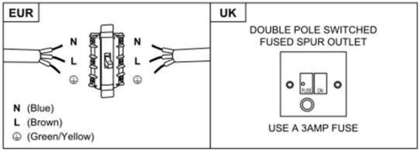
The fuse must be rated at 3 Amps.
Standard Installation Accessories List
| Spec. | Illustration Picture | Qty |
| Casing | 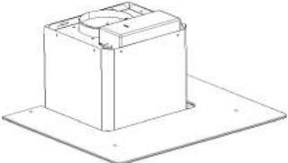 | 1 |
| Upper Chimney | 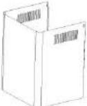 | 1 |
| Lower Chimney | 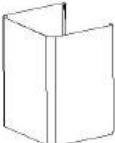 | 1 |
| Lower chimney bracket | 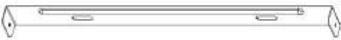 | 1 |
| Upper chimney bracket | 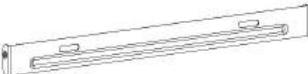 | 1 |
| Hanging Board | 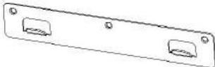 | 1 |
| φ8 rawl plugsφ8×φ6 white color | 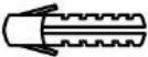 | 9 |
| ScrewsST4.0×30 | 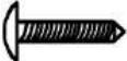 | 9 |
| φ7.2screwsST4.0×8 |  | 2 |
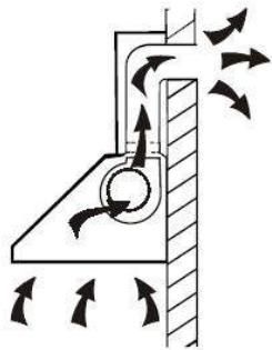
If you have an outlet to the outside, your cooker hood can be connected as below picture by means of an extraction duct (enamel, aluminum, flexible pipe or inflammable material with an interior diameter of 150mm)
natural_image
Diagram of airflow around a mechanical component with directional arrows indicating movement (no text or symbols)- Before installation, turn the unit off and unplug it from the outlet.
- The cooker hood should be placed at a distance of 65\~75cm above the cooking plane for best effect.
- Drill 3 x 8mm holes to accommodate the bracket. Screw and tighten the bracket onto the wall with the screws provided.

For inclined panel Model
- eed to drill 2x8mm extra holes & fixing screws & screw plugs before installation. Voor schuine modellen

natural_image
Technical line drawing of a mechanical component with mounting holes and a central circular feature (no text or symbols)- Leave up the cooker hood and hang onto the wall bracket hook.
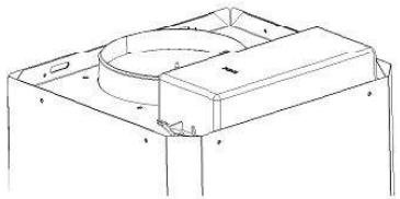
- Fix the one-way-valve to the air outlet of the cooker hood. Then, attached the exhaust pipe onto the one-way-valve as shown below.

6.
i. Place the glass in appropriate position on the top the cooker hood.
ii. Fix with 4 screws and washer. In order to avoid the glass cracking, please do not tighten the screws too strongly.
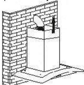
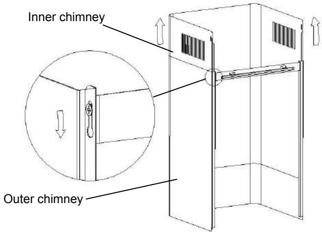
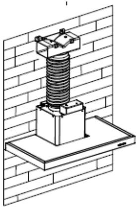
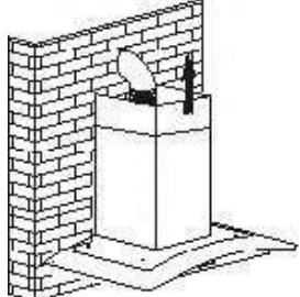
i. By Put the inner chimney into outer chimney . Then pulling out the inner chimney upwards. Adjust to reach the height required.
natural_image
Diagram of a brick wall with a container and a person inserted, no text or symbols presentii. Sliding the chimney to adjust the chimney height. When the height you required is reached, then hang the fixing hole to the fixing screws as showed in below pictures.
8.
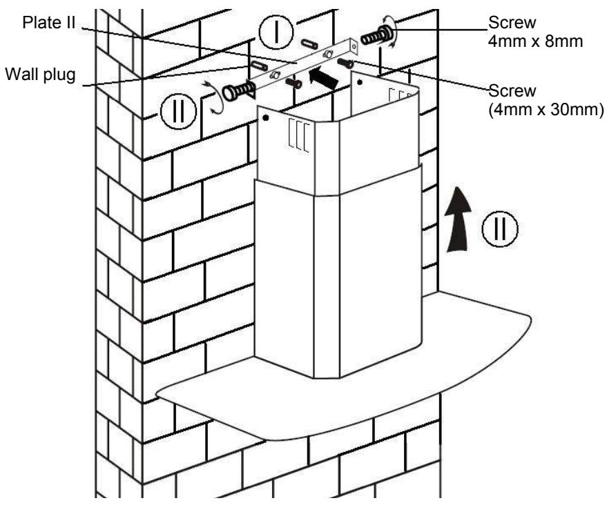
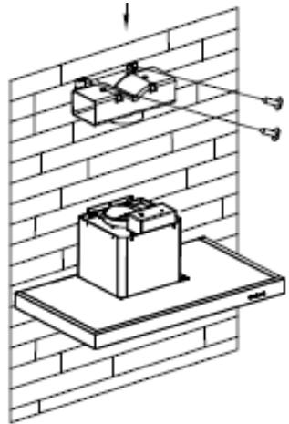
i. Drill 2 x 8mm holes to accommodate the plate II. Screw and tighten the plate II onto the wall with 2 screws provided.
ii. Assembly the chimney onto the unit and fix it with 2 screws.
Standard Installation Accessories List
| Spec. | Illustration Picture | Qty |
| Air Deflector |  | 1 |
| Bracket |  | 1 |
| φ8 rawl plugsφ8×φ6 white color | 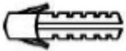 | 2 |
| ScrewsST4.0×30 | 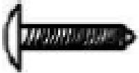 | 2 |
| ScrewsST3.5×12 | 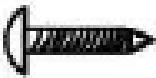 | 2 |
INSTALLATION(AIR DEFLECTOR FOR T-SHAPE,CURVED GLASS,FLAT GLASS MODELS):
Air deflector is mentioned as included and not optional.
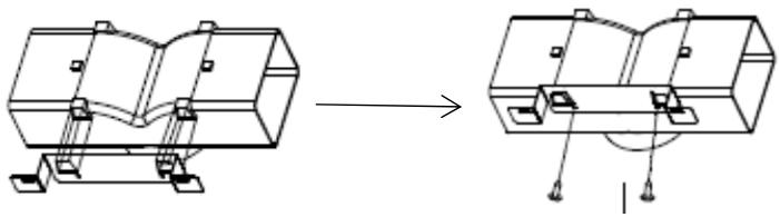
- Before installation, curve both ends of the bracket as shown below:
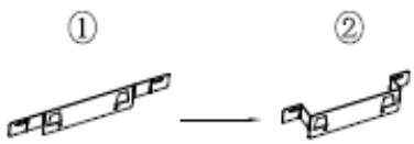
- Fix the bracket to the T-shaped plastic outlet with 2pcs ST3.5x12mm screws provided.
natural_image
Technical line drawing of a mechanical assembly before and after modification (no text or symbols)- Drill 2 holes to accommodate the wall plugs, then screw and tighten the bracket onto the wall with 2pcs ST4x30mm screws provided.
natural_image
Technical line drawing of a mechanical assembly mounted on a brick wall, showing components and alignment (no text or symbols)- Attach the exhaust pipe onto the air outlet of the cooker hood as shown below:
natural_image
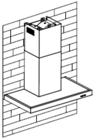
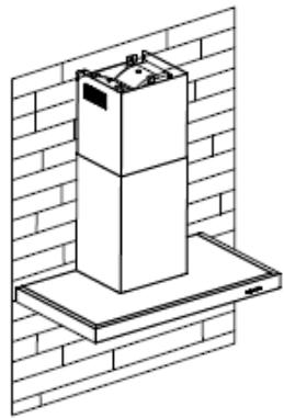
Technical line drawing of a mechanical assembly mounted on a brick wall (no text or symbols)- Install the chimney to the unit and fix it.
natural_image
Isometric line drawing of a multi-tiered appliance mounted on a base, set against a brick wall (no text or symbols)o “Please kindly be noted: T-shaped plastic outlet and v-flaps can not be used at the same time. You can use them in two ways: 1) Add v-flap on existing outlet; 2) Use T-shaped plastic outlet, no add v-flap.”
o “Note: The product is provided with v-flap accessory. This accessory is not mandatory for installation, operation and use of the product.”
Standard Installation Accessories List
| Spec. | Illustration Picture | Qty |
| Air Deflector | 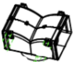 | 1 |
| Bracket |  | 1 |
| φ8 rawl plugsφ8×φ6 white color | 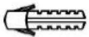 | 2 |
| ScrewsST4.0×30 | 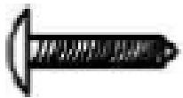 | 2 |
| ScrewsST3.5×12 | 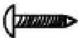 | 2 |
INSTALLATION (AIR DEFLECTOR FOR PYRAMID & SLANT MODELS):
Air deflector is mentioned as included and not optional.
- Fix the bracket to the T-shaped plastic outlet with 2pcs ST3.5x12mm screws provided as shown below:
natural_image
Diagram showing two 3D mechanical components with alignment guides, no text or symbols present- Drill 2 holes on the wall to accommodate the wall plugs, then screw and tighten the bracket onto the wall with 2pcs ST4x30mm screws provided.

natural_image
Technical diagram showing a mounted device mounted on a metal frame, with no visible text or symbols.- Attach the exhaust pipe onto the air outlet of the cooker hood as shown below:
natural_image
Technical line drawing of a black smokestack mounted on a metal frame against a brick wall (no text or symbols)- Install the chimney to the unit and fix it.
natural_image
Line drawing of a chimney mounted on a brick wall (no text or symbols)o “Please kindly be noted: T-shaped plastic outlet and v-flaps can not be used at the same time. You can use them in two ways: 1) Add v-flap on existing outlet; 2) Use T-shaped plastic outlet, no add v-flap.”
o “Note: The product is provided with v-flap accessory. This accessory is not mandatory for installation, operation and use of the product.”
INSTALLATION (VENT INSIDE)
If you do not have an outlet to the outside, exhaust pipe is not required and the installation is similar to the one show in section "INSTALLATION (VENT
OUTSIDE").
natural_image
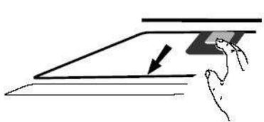
Diagram of a mechanical or fluid system with directional arrows indicating flow or movement (no text or symbols)Activated carbon filter can be used to trap odors.
In order to install the activated carbon filter, the grease filter should be detached first. Press the lock and pull it downward.
natural_image
Simple line drawing of a hand pressing down on a flat surface with a downward arrow (no text or symbols)
natural_image
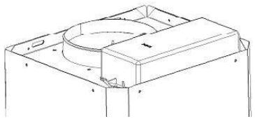
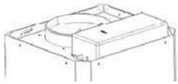
Simple line drawing of a hand pressing down on a laptop keyboard (no text or symbols)Plug the activated carbon filter into the unit and turn it in clockwise direction. Repeat the same on the other side.
natural_image
Technical line drawing of a mechanical fan or motor assembly with no visible text or symbolsNOTE:
o Make sure the filter is securely locked. Otherwise, it would loosen and cause dangerous.
When activated carbon filter attached, the suction power will be lowere
CONFIGURATION 1
1
2
3

OPERATION
Button 1
The button is with indicate backlit, when you press the button, the backlit will be turned on and the fan will be turned on at low speed. when press again, it will turn off the fan.
It's used for Ventilation on the kitchen. It is suitable for simmering and cooking which do not make much steam.
Button 2
The button is with indicate backlit, when you press the button, the backlit will be turned on and the fan will be turned on at Medium Speed. when press again, it will turn off the fan.
Airflow speed is ideally for ventilation in standard cooking operation.
Button 3
The button is with indicate backlit, when you press the button, the backlit will be turned on and the fan will be turned on at High Speed. when press again,. it will turn off the fan.
When high density of smoke or steam produced, press high-speed button for highest effective ventilation.
NOTE: If Low / Medium / High speed buttons are press at the same time, the unit will only operate at the highest speed.
Light button

CONFIGURATION 2
0
1
2
3

OPERATION
Off button 0
It's used for turning off the fan.
Low Speed button 1
It's used for Ventilation on the kitchen. It is suitable for simmering and cooking which do not make much steam.
Medium Speed button 2
Airflow speed is ideally for ventilation in standard cooking operation.
High Speed button 3
When high density of smoke or steam produced, press high-speed button for highest effective ventilation.
NOTE: If Low / Medium / High speed buttons are press at the same time, the unit will only operate at the highest speed.
Light button

CONFIGURATION 3


① On/Off button
It's used for turning on/off the fan.
+ Speed plus button
For increasing the speed of the fan
- Speed decrease button
For decreasing the speed of the fan.
Light button
8 Digital display
Fan speed display:"1" for Low speed, "2" for Medium speed, "3" for High speed, "4" for Booster function.
Quick timer: Press + & - hold for 1 second, Digital display will flashing & into 5 minutes count down, after 5 minutes motor & light will turn off automatic & Buzzer sound for 1 second.
Booster function
This hood has a booster function. To activate the booster, Press ☐ to speed 4, enter into highest speed while the hood is in use and it will increase speed for 5 minutes, before slowing down again.
CONFIGURATION 4


Timer button
- Setting the time of the day
When hood in standby mode (motor not working), press the timer button to enter the time setting.
Press the 'Fan speed' key to set the hour of the day and press the 'Light' key to set the minute.
- Setting the Timer
When the hood is in operation mode, press the timer button to set the countdown.
Press the timer button one timer then the countdown will increase one minute. The max countdown is 60 minutes.

Speed decrease button
For decreasing the speed of the fan.

Speed plus button
For increasing the speed of the fan

LIGHT Button
For lighting ON & OFF.
LCD display
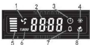
- Motor symbol, will rotate when the motor is working;
- Time display;
- Timer symbol, will appear when timer is setting and counting;
- Light symbol;
- Motor speed;
- Turbo speed symbol, will appear when the speed is highest setted;
- Alarm symbol, will appear 5 seconds when the counting down of timer is over.
- Cleanning alarm, appear when total working time up to 14 hours or at the first time using after plugging.
CONFIGURATION 5

STANDBYMODE.
After plug in, all lighting, system in STANDBY MODE.
1 Low Speed button
It's used for Ventilation on the kitchen. It is suitable for simmering and cooking which do not make much steam.
2 Medium Speed button
Airflow speed is ideally for ventilation in standard cooking operation.
3 High Speed button
When high density of smoke or steam produced, press high-speed button for high effective ventilation.
B Booster function
This hood has a booster function. To activate the booster, Press
B to speed 4, enter into highest speed while the hood is in use and it will increase speed for 5 minutes, before slowing down again.

Light
For lighting ON & OFF.
MAINTENANCE
Before cleaning switch the unit off and pull out the plug.
I. Regular Cleaning
Use a soft cloth moistened with hand-warm mildly soapy water or household cleaning detergent. Never use metal pads, chemical, abrasive material or stiff brush to clean the unit.
II. Monthly Cleaning for Grease Filter
ESSENTIAL: Clean the filter every month can prevent any risk of fire.
The filter collects grease, smoke and dust..... so the filter is directly affecting the efficiency of the cooker hood. If not cleaned, the grease residue (potential flammable) will saturate on the filter. Clean it with household cleaning detergent.
III. Annual Cleaning for Activated Carbon Filter
Apply SOLELY to unit that installed as a recirculation unit (not vented to the outside). This filter traps odors and must be replaced at least once a year
depending on how frequent the cooker hood used.
IV. Changing a light bulb
Remove the screws on the glass, take off the hood glass. Find the bulb that requires replacement, you will find it located in the light fixture which is inside the exposed section of the canopy.
natural_image
Pure electrical circuit lines without any symbolsDisconnect the light wiring point and remove the bulb holders and wiring from the hood. Important: It's not possible to replace the bulbs individually, it will be necessary to obtain the bulbs, bulb holders and wiring as a complete part. (LED light: MAX 1.5W)
Fit the replacement bulbs, bulb holders and wiring in the same manners as the originals. Then reconnect the light wiring point.
Refit the hood glass and fasten the glass screws. Make sure the screws are fully tightened.
TROBULESHOOTING
| Fault | Cause | Solution |
| Light on, but fan does not work | The fan blade is jammed. | Switch off the unit and repair by qualified service personnel only. |
| The motor is damaged. | ||
| Both light and fan do not work | Halogen light bulb burn. | Replace the bulb with correct rating. |
| Power cord looses. | Plug in to the power supply again. | |
| Serious Vibration of the unit | The fan blade is damaged. | Switch of the unit and repair by qualified service personnel only. |
| The fan motor is not fixed tightly. | Switch off the unit and repair by qualified service personnel only. | |
| The unit is not hung properly on the bracket. | Take down the unit and check whether the bracket is in proper location. | |
| Suction performance not good | Too long distance between the unit and the cooking plane | Readjust the distance to 65-75cm |
CUSTOMER ASSISTANCE SERVICE
If you cannot identify the cause of the operating anomaly, switch off the appliance and contact the Assistance Service.
PRODUCT SERIAL NUMBER. Where can I find it?
It is important you to inform the Assistance Service of your product code and its serial number (a 16 character code which begins with the number 3); this can be found on the guarantee certificate or on the data plate located on the appliance.
It will help to avoid wasted journeys to technicians, thereby (and most significantly) saving the corresponding callout charges.
ENVIRONMENTAL PROTECTION
Waste electrical products should not be disposed of with household waste. Please recycle where facilities exist. Check with your Local Authority or retailer for recycling advice.
This appliance is marked according to the European directive 2012/19/EU on Waste Electrical and Electronic Equipment (WEEE).
By ensuring this product is disposed of correctly, you will help prevent potential negative consequences for the environment and human health, which could otherwise be caused by inappropriate waste handling of this product.
The symbol on the product indicates that this product may not be treated as household waste. Instead it shall be handed over to the applicable collection point for the recycling of electrical and electronic equipment Disposal must be carried out in accordance with local environmental regulations for waste disposal.
For more detailed information about treatment, recovery and recycling of this product, please contact your local city office, your household waste disposal service or the shop where you purchased the product.
NOTICE D'INSTALLATION ET
D'UTILISATION
Sommaire
INTRODUCTION 77
Installation (Evacuation) 81
Installation (Recyclage) 92
The appliance must be connected directly to the mains using an omnipolar circuit breaker with a minimum opening of 3mm between the contacts.
The cable must not be bent or compressed.
natural_image
Diagram of a mechanical or fluidic system with directional arrows indicating flow or movement (no text or symbols present)natural_image
Technical line drawing of a mechanical component with mounting holes and a central circular feature (no text or symbols)natural_image
Diagram of a coiled tube with a downward arrow indicating compression or reduction (no text or symbols)Hotte

natural_image
Technical line drawing of a mechanical component with no visible text or symbols6.
natural_image
Technical line drawing of a mechanical assembly with mounting brackets (no text or symbols)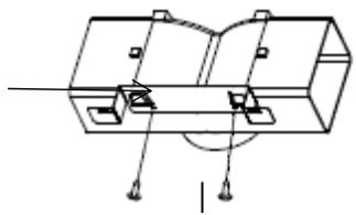
natural_image
Pure mechanical assembly diagram without any text, numbers, or symbolsnatural_image
Technical line drawing of a brick wall assembly with two components, no text or symbols presentnatural_image
Technical line drawing of a mechanical assembly mounted on a brick wall (no text or symbols)natural_image
Isometric line drawing of a cabinet mounted on a brick wall (no text or symbols)natural_image
Diagram showing a mechanical assembly before and after transformation, with no visible text or symbols.natural_image
Technical line drawing of a mechanical assembly mounted on a chimney against a brick wall (no text or symbols)natural_image
Technical line drawing of a chimney mounted on a base against a brick wall background (no text or symbols)natural_image
Line drawing of a double-bell chimney mounted on a brick wall (no text or symbols)natural_image
Diagram of a conical structure with directional arrows indicating force or movement (no text or symbols)natural_image
Simple line drawing of a hand pressing down on a flat surface with a downward arrow (no text or symbols)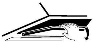
natural_image
Simple line drawing of a hand pressing down on a flat surface with a curved arrow indicating rotation (no text or symbols)natural_image
Technical line drawing of a mechanical component with no visible text or symbolsEnclenché
NOTE :
For decreasing the speed of the fan.

Bouton d'éclairage
8 Digital display
Fan speed display:"1" for Low speed, "2" for Medium speed, "3" for High speed, "4" pour la fonction Booster.
Quick timer: Press + & - hold for 1 second, Digital display will flashing & into 5 minutes count down, after 5 minutes motor & light will turn off automatic & Buzzer sound for 1 second.
Fonction booster
natural_image
Pure electrical circuit lines without any symbolsBlau = N Oder Neutral
natural_image
Diagram of airflow around a mechanical component with directional arrows indicating movement (no text or symbols)natural_image
Technical line drawing of a mechanical component with mounting holes and a central circular feature (no text or symbols)natural_image
Isometric line drawing of a brick wall with a small cylindrical object inserted, no text or symbols presentnatural_image
Technical line drawing of a mechanical assembly with two views (no text or symbols)natural_image
Technical line drawing of a battery mounted on a brick wall, showing mounting bracket and wiring (no text or symbols)natural_image
Isometric line drawing of a mechanical assembly mounted on a brick wall (no text or symbols)natural_image
Isometric line drawing of a multi-tiered cylindrical device mounted on a base, set against a brick wall (no text or symbols)natural_image
Diagram showing a mechanical assembly before and after transformation, with no visible text or symbols.natural_image
Technical line drawing of a roof structure with a mounted component and a chimney, set against a brick wall (no text or symbols)natural_image
Technical line drawing of a chimney mounted on a base, set against a brick wall background (no text or symbols)natural_image
Line drawing of a double-bell tower mounted on a brick wall (no text or symbols)natural_image
Diagram of a mechanical or fluid system with directional arrows indicating flow or movement (no text or symbols)natural_image
Simple line drawing of a hand pressing down on a flat surface with an arrow indicating downward motion (no text or symbols)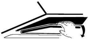
natural_image
Simple line drawing of a hand pressing down on a laptop keyboard (no text or symbols)natural_image
Technical line drawing of a mechanical fan or motor assembly with no visible text or symbolsHINWEIS:
natural_image
Pure electrical circuit lines without any symbolsnatural_image
Diagram of airflow around a mechanical component with directional arrows indicating movement (no text or symbols)natural_image
Technical line drawing of a mechanical component with mounting holes and a central circular feature (no text or symbols)natural_image
Diagram of a pipe with a coiled tube and a downward arrow indicating flow or direction (no text or symbols)Καπέλο
natural_image
Technical line drawing of a mechanical housing or enclosure with no visible text or symbols6.
natural_image
Isometric line drawing of a brick wall with a small object inside, no text or symbols presentnatural_image
Technical line drawing of a mechanical assembly before and after modification (no text or symbols)natural_image
Technical line drawing of a mechanical assembly mounted on a brick wall, showing two components with no visible text or symbols.natural_image
Technical line drawing of a mechanical assembly mounted on a base plate against a brick wall (no text or symbols)natural_image
Isometric line drawing of a cabinet mounted on a base against a brick wall (no text or symbols)natural_image
Diagram showing a mechanical assembly before and after transformation, with no visible text or symbols.natural_image
Technical line drawing of a mechanical device mounted on a platform against a brick wall background (no text or symbols)natural_image
Technical line drawing of a black metal chimney mounted on a white base, against a brick wall background (no text or symbols)natural_image
Line drawing of a chimney mounted on a brick wall (no text or symbols)natural_image
Diagram of a mechanical or fluid system with directional arrows indicating flow or movement (no text or symbols)natural_image
Simple line drawing of a hand pressing down on a flat surface with an arrow indicating downward motion (no text or symbols)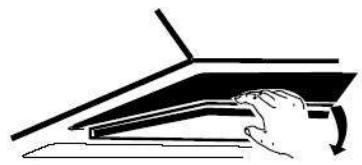
natural_image
Simple line drawing of a hand pressing down on a laptop keyboard (no text or symbols)natural_image
Technical line drawing of a mechanical fan or motor assembly (no text or symbols visible)ΣΗΜΕΙΩΣΗ:
CLOSE
natural_image
Pure electrical circuit lines without any symbolsnatural_image
Diagram of airflow around a mechanical component with directional arrows indicating movement (no text or symbols)Per inclinato Modello pannello
natural_image
Technical line drawing of a mechanical component with mounting holes and a central circular feature (no text or symbols)natural_image
Diagram of a pipe with a downward arrow indicating flow or direction (no text or symbols)Cappa

natural_image
Technical line drawing of a mechanical housing or enclosure with no visible text or symbols6.
natural_image
Isometric line drawing of a brick wall with a box and a small object inside (no text or symbols)natural_image
Technical line drawing of a mechanical assembly before and after modification (no text or symbols)natural_image
Technical line drawing of a mechanical assembly mounted on a brick wall, showing two components and alignment arrows (no text or symbols)natural_image
Technical line drawing of a mechanical assembly mounted on a brick wall (no text or symbols)natural_image
Isometric line drawing of a multi-tiered storage unit mounted on a brick wall (no text or symbols)natural_image
Diagram showing a mechanical assembly before and after transformation, with no visible text or symbols.natural_image
Technical line drawing of a mechanical component mounted on a brick wall, with no visible text or symbols.natural_image
Line drawing of a black chimney mounted on a base against a brick wall background (no text or symbols)natural_image
Line drawing of a three-tiered chimney mounted on a brick wall (no text or symbols)natural_image
Diagram of a mechanical or fluid system with directional arrows and a central block, no text or symbols present.natural_image
Simple line drawing of a hand pressing down on a flat surface with a downward arrow (no text or symbols)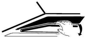
natural_image
Simple line drawing of a hand pressing down on a laptop keyboard (no text or symbols)natural_image
Technical line drawing of a mechanical component with no visible text or symbolsNOTE:
natural_image
Pure electrical circuit lines without any symbols(Waste Electrical and Electronic Equipment - WEEE).
natural_image
Diagram of airflow around a mechanical component with directional arrows indicating movement (no text or symbols)natural_image
Technical line drawing of a mechanical component with mounting holes and a central circular feature (no text or symbols)natural_image
Diagram of a coiled pipe with a downward arrow indicating flow or compression (no text or symbols)Okap

natural_image
Technical line drawing of a mechanical component with mounting flanges and a central circular feature (no text or symbols)6.
natural_image
Diagram of a brick wall with a chimney and support structure (no text or symbols)natural_image
Technical line drawing of a mechanical assembly before and after modification (no text or symbols)natural_image
Technical line drawing of a mechanical assembly mounted on a brick wall (no text or symbols)natural_image
Isometric line drawing of a cabinet mounted on a brick wall (no text or symbols)natural_image
Diagram showing a mechanical assembly before and after transformation, with no visible text or symbols.natural_image
Technical diagram of a ceiling-mounted device mounted on a brick wall, with no visible text or symbols.natural_image
Technical line drawing of a chimney mounted on a base, set against a brick wall background (no text or symbols)natural_image
Line drawing of a chimney mounted on a brick wall (no text or symbols)natural_image
Diagram of a mechanical or fluid system with directional arrows and a central block, no text or symbols present.natural_image
Simple line drawing of a hand pressing down on a flat surface with a downward arrow (no text or symbols)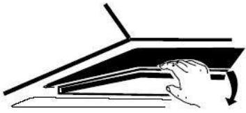
natural_image
Simple line drawing of a hand pressing down on a laptop keyboard (no text or symbols)natural_image
Technical line drawing of a mechanical component with no visible text or symbolsUWAGA:
natural_image
Pure electrical circuit lines without any symbolsnatural_image
Symbol of a trash bin with crossed lines indicating no waste or discharge (no text or labels)Regulations concerning the discharge of air have to be fulfilled.
natural_image
Diagram of airflow around a mechanical component with directional arrows indicating movement (no text or symbols)Parafuso (4mm x 30mm)
Para modelos com painel inclinado
natural_image
Technical line drawing of a mechanical component with mounting holes and a central circular feature (no text or symbols)natural_image
Isometric line drawing of a brick wall with a box and a small object inside (no text or symbols)natural_image
Technical line drawing of a mechanical assembly with two views (no text or symbols)natural_image
Technical line drawing of a battery mounted on a brick wall, showing mounting bracket and base plate (no text or symbols)- Conecte o tubo de escape na saída de ar do exaustor, como mostrado abaixo:
natural_image
Technical line drawing of a mechanical assembly mounted on a brick wall (no text or symbols)natural_image
Isometric line drawing of a cabinet mounted on a brick wall (no text or symbols)natural_image
Diagram showing a mechanical assembly before and after transformation, with no visible text or symbols.natural_image
Technical line drawing of a mechanical assembly mounted on a platform, with no visible text or symbols.natural_image
Technical line drawing of a black metal chimney mounted on a white base against a brick wall (no text or symbols)natural_image
Line drawing of a chimney mounted on a brick wall (no text or symbols)natural_image
Diagram of a mechanical or fluid system with directional arrows and a central block (no text or symbols)natural_image
Simple line drawing of a hand holding a rectangular object with an arrow, no text or symbols present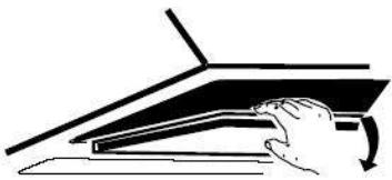
natural_image
Simple line drawing of a hand pressing down on a laptop keyboard (no text or symbols)natural_image
Technical line drawing of a mechanical fan or motor assembly (no text or symbols visible)NOTA:
natural_image
Pure electrical circuit lines without any symbolsnatural_image
Diagram of airflow around a mechanical component with directional arrows indicating movement (no text or symbols)natural_image
Diagram of a brick wall with a mechanical component and directional arrows indicating movement (no text or symbols)Surub (4mmx30mm)
107.5mm
natural_image
Technical line drawing of a mechanical component with mounting holes and a central circular feature (no text or symbols)natural_image
Diagram of a brick wall with a box and a small object inside, no text or symbols present8.
Lista accesoriiilor standard de instalare
| Spec. | Imagine | Cant |
| deflector de aer | 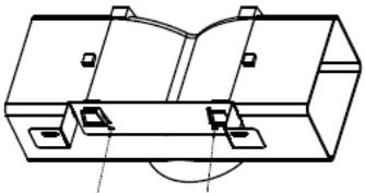 | 1 |
| paranteză | 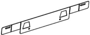 | 1 |
| Bolturi de φ8 | 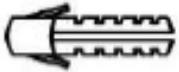 | 2 |
| Suruburi ST4.0×30 | 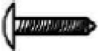 | 2 |
| Suruburi ST3.5×12 | 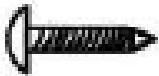 | 2 |
INSTALARE (DEFLECTOR DE AER PENTRU T-SHAPE, STICLA CURBĂ, MODELE DE STICLĂ):
natural_image
Technical line drawing of a mechanical assembly before and after modification (no text or symbols)natural_image
Technical line drawing of a battery mounted on a platform against a brick wall, with no visible text or symbols.natural_image
Technical line drawing of a mechanical assembly mounted on a brick wall (no text or symbols)natural_image
Isometric line drawing of a cabinet mounted on a base against a brick wall (no text or symbols)natural_image
Diagram showing a mechanical assembly transformation, with no visible text or symbolsnatural_image
Technical line drawing of a chimney with a mounted sensor array and a flat base, set against a brick wall (no text or symbols)natural_image
Technical line drawing of a chimney mounted on a brick wall (no text or symbols)natural_image
Line drawing of a double-bell chimney mounted on a brick wall (no text or symbols)natural_image
Diagram of a mechanical or fluid system with directional arrows indicating flow or movement (no text or symbols)natural_image
Simple line drawing of a hand pressing down on a flat surface with an arrow indicating downward motion (no text or symbols)
natural_image
Simple line drawing of a hand pressing down on a laptop keyboard (no text or symbols)natural_image
Technical line drawing of a mechanical fan assembly with no visible text or symbolsNOTĂ:
natural_image
Pure electrical circuit lines without any symbolsnatural_image
Diagram of airflow around a mechanical component with directional arrows indicating movement (no text or symbols)- Pred priključitevanjem cevi izklopite napo in potegnite vtikač iz vtičnice.

- Napa bo najbolj učinkovita, če bo od kuhalne površine oddaljena 65\~75cm.
- Za nosilec izvrtajte 3 luknje s premerom 8 mm. Nosilec pritirdite na zid s priloženimi vijaki; dobro jih zategnite.
natural_image
Technical line drawing of a mechanical component with mounting holes and a central circular feature (no text or symbols)- Napo obesite na kavlje na nosilcu, ki ste ga pritrdili na zid.

natural_image
Diagram of a coiled pipe with a downward arrow indicating flow or compression (no text or symbols)Kuhinjska napa
natural_image
Technical line drawing of a mechanical component with no visible text or symbols6.
i. Namestite stekleni del na kuhinjsko napo v pravilnem položaju.
ii. Pritrdite ga s 4 vijaki s podložko. Vijakov ne zategujte preveč, da steklo ne bi počilo.
i. Vstavite notranji del dimnika v zunanji del dimnika. Nato potegnite notranji del dimnika navzgor. Prilagodite višino.
natural_image
Technical line drawing of a mechanical assembly mounted on a brick wall (no text or symbols)natural_image
Mechanical assembly diagram showing a component before and after modification (no text or symbols)- Zadite 2 luknji za pritrditev stenskih čepov, nato privijte in pritrdite nosilec na steno s priloženimi vijaki 2pcs ST4x30mm.
natural_image
Technical line drawing of a brick wall assembly with two components, no text or symbols presentnatural_image
Technical line drawing of a mechanical assembly mounted on a brick wall (no text or symbols)- Namestite dimnik na enoto in ga pritrdite.
natural_image
Isometric line drawing of a multi-tiered storage unit mounted on a brick wall (no text or symbols)natural_image
Two technical diagrams showing mechanical components with alignment indicators (no text or symbols)2.Držite 2 luknji na steni, da namestite stenske čepe, nato privijte in pritrdite nosilec na steno s priloženimi vijaki 2pcs ST4x30mm.
natural_image
Technical diagram of a roof structure with a mounted component and a conical chimney, set against a brick wall (no text or symbols)natural_image
Technical line drawing of a black metal chimney mounted on a base, against a brick wall background (no text or symbols)- Namestite dimnik na enoto in ga pritrdite.
natural_image
Line drawing of a chimney mounted on a brick wall (no text or symbols)natural_image
Diagram of a mechanical or fluid system with directional arrows indicating flow or movement (no text or symbols)V tem primeru v napo vstavite filter z aktivnim oglem, ki zadrži vonjave. Najprej morate sneti filter za maščobe, nato pa lahko vstavite ogleni filter. Potisnite na zapah in potegnite filter za maščobe navzdol.
natural_image
Simple line drawing of a hand pressing down on a flat surface with a downward arrow (no text or symbols)
natural_image
Simple line drawing of a hand pressing down on a laptop keyboard (no text or symbols)Potisnite aktivni ogleni filter v napo in ga zavrtite v desno, v smeri vrtenja urinega kazalca. Postopek ponovite na drugi strani nape.

natural_image
Technical line drawing of a mechanical fan or motor assembly with no visible text or symbols(PRITRJEVANJE)
OPOMBA:
natural_image
Pure electrical circuit lines without any symbolsOdklopite žico za žarnico in z nape odklopite držalo žarnice in žico. Pomembno: Ni mogoče zamenjati samo žarnico, ampak potrebujete komplet – žarnico, nosilec in žico. (lučka LED: G4, MAX 1.5W)
Pritrdite novo žarnico z nosilcem in žico tako, kot je bila pritrjena pregorela žarnica. Nato ponovno priključite žico.
Ponovno namestite steklo in privijte vijake. Prepričajte se, da ste jih do konca zategnili.
ODPRAVLJANJE NEPRAVILNOST V DELOVANJU
natural_image
Diagram of airflow around a mechanical component with directional arrows indicating movement (no text or symbols)natural_image
Technical line drawing of a mechanical component with mounting holes and a central circular feature (no text or symbols)natural_image
Diagram showing a coiled tube with a downward arrow and a 3D mechanical component below (no text or symbols)6.
natural_image
Diagram of a brick wall with a container and a person standing inside, no text or symbols presentnatural_image
Technical line drawing of a mechanical assembly before and after modification (no text or symbols)natural_image
Technical line drawing of a mechanical assembly mounted on a brick wall, showing components and alignment (no text or symbols)natural_image
Technical line drawing of a mechanical assembly mounted on a brick wall (no text or symbols)5.Instale la chimenea a la unidad y fijela.
natural_image
Isometric line drawing of a vertical cylindrical structure mounted on a base, against a brick wall background (no text or symbols)natural_image
Diagram showing a mechanical assembly before and after transformation, with no visible text or symbols.natural_image
Technical line drawing of a chimney mounted on a brick wall, with no visible text or symbolsnatural_image
Technical line drawing of a chimney mounted on a base against a brick wall (no text or symbols)natural_image
Line drawing of a chimney mounted on a brick wall (no text or symbols)natural_image
Diagram of a mechanical or fluid system with directional arrows indicating flow or movement (no text or symbols)natural_image
Two-step diagram showing hand pressing a component into a flat panel, with no text or symbols present.natural_image
Technical line drawing of a mechanical fan or motor assembly with no visible text or symbolsNOTA:
natural_image
Pure electrical circuit lines without any symbolsINSTALLATIE (VENTILATIE BUITEN) 307
INSTALLATIE (VENTILATIE BINNEN) 318
BESCHRIJVING VAN DE COMPONENTEN 319
WERKING 319
ONDERHOUD 324
PROBLEMEN OPLOSSEN 325
OVEREENSTEMMING MET RICHTLIJNEN 325
MILIEUBESCHERMING 325
Blauw = N of Neutrale
natural_image
Diagram of airflow around a mechanical component with directional arrows indicating movement (no text or symbols)natural_image
Technical line drawing of a mechanical component with mounting holes and a central circular feature (no text or symbols)natural_image
Diagram of a pipe with a curved duct and a downward arrow indicating flow or direction (no text or symbols)Afzuigkap

natural_image
Technical line drawing of a mechanical component with no visible text or symbols6.
natural_image
Diagram of a brick wall with a container and a tool, no text or symbols presentnatural_image
Technical line drawing of a mechanical assembly before and after modification (no text or symbols)natural_image
Technical line drawing of a battery mounted on a brick wall, showing mounting and mounting components (no text or symbols)natural_image
Technical line drawing of a mechanical assembly mounted on a brick wall (no text or symbols)natural_image
Technical line drawing of a mechanical assembly mounted on a brick wall (no text or symbols)natural_image
Diagram showing a mechanical assembly before and after transformation, with no visible text or symbols.natural_image
Technical line drawing of a chimney with a mounted sensor array and a base, mounted on a brick wall (no text or symbols)natural_image
Technical line drawing of a chimney mounted on a base, against a brick wall background (no text or symbols)natural_image
Line drawing of a chimney mounted on a brick wall (no text or symbols)INSTALLATIE (BINNEN VENTILATIE)
natural_image
Diagram of a conical device with directional arrows indicating motion or force, no text or symbols presentnatural_image
Simple line drawing of a hand pressing down on a flat surface with an arrow indicating downward motion (no text or symbols)
natural_image
Simple line drawing of a hand pressing down on a laptop keyboard (no text or symbols)natural_image
Technical line drawing of a mechanical fan or motor assembly with no visible text or symbolsNOTA:
natural_image
Pure electrical circuit lines without any symbolsnatural_image
Diagram of airflow around a mechanical component with directional arrows indicating movement (no text or symbols)natural_image
Technical line drawing of a mechanical component with mounting brackets and alignment lines (no text or symbols)natural_image
Diagram of a coiled tube with a downward arrow indicating compression or reduction (no text or symbols)مدخنة موقد الطهي
natural_image
Technical line drawing of a mechanical component with no visible text or symbols.6
natural_image
Diagram of a brick wall with a container and an upward arrow, no text or symbols presentnatural_image
Technical line drawing of a mechanical assembly before and after modification (no text or symbols)natural_image
Technical line drawing of a mechanical assembly mounted on a brick wall, showing components and alignment (no text or symbols)natural_image
Technical line drawing of a mechanical assembly mounted on a brick wall (no text or symbols)natural_image
Isometric line drawing of a vertical cylindrical structure mounted on a rectangular base, against a brick wall background (no text or symbols)natural_image
Diagram showing a mechanical assembly before and after transformation, with no visible text or symbols.natural_image
Technical line drawing of a chimney with a mounted sensor array and a flat roof, set against a brick wall (no text or symbols)natural_image
Technical line drawing of a black metal chimney mounted on a base, against a brick wall background (no text or symbols)natural_image
Line drawing of a chimney mounted on a brick wall (no text or symbols)natural_image
Diagram of a conical structure with directional arrows indicating motion or force, no text or symbols presentnatural_image
Simple line drawing of a hand pressing down on a flat surface with an arrow indicating downward motion (no text or symbols)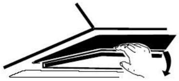
natural_image
Simple line drawing of a hand pressing down on a laptop keyboard (no text or symbols)natural_image
Technical line drawing of a mechanical fan or motor assembly (no text or symbols visible)ملاحظة:
natural_image
Pure electrical circuit lines without any symbolsnatural_image
Diagram of a mechanical or fluidic system with directional arrows indicating flow or movement (no text or symbols present)natural_image
Technical line drawing of a rectangular panel with mounting holes and internal components, no text or symbols presentnatural_image
Diagram of a pipe with a downward arrow indicating flow or direction (no text or symbols)natural_image
Technical line drawing of a mechanical component with no visible text or symbols6.
natural_image
Simple line drawing of a brick wall with a container and a small object inside (no text or symbols)natural_image
Technical line drawing of a mechanical assembly before and after modification (no text or symbols)natural_image
Technical line drawing of a battery mounted on a brick wall, showing mounting structure and wiring (no text or symbols)natural_image
Technical line drawing of a mechanical assembly mounted on a brick wall (no text or symbols)natural_image
Isometric line drawing of a cabinet mounted on a platform against a brick wall (no text or symbols)natural_image
Diagram showing a mechanical component before and after assembly, with no visible text or symbolsnatural_image
Diagram of a kitchen range setup with a conical oven and a mounted device, shown against a brick wall (no text or symbols)natural_image
Line drawing of a black metal chimney mounted on a white brick wall (no text or symbols)natural_image
Line drawing of a chimney mounted on a brick wall (no text or symbols)natural_image
Diagram of a mechanical or fluid system with directional arrows indicating flow or movement (no text or symbols)natural_image
Simple line drawing of a hand pressing down on a flat surface with an arrow indicating downward motion (no text or symbols)
natural_image
Simple line drawing of a hand pressing down on a flat surface with a curved arrow indicating motion (no text or symbols)natural_image
Technical line drawing of a mechanical fan or motor with a circular arrow indicating 'CLOSE' (no text or symbols on the diagram itself)ЗАБЕЛЕЖКА:
natural_image
Pure electrical circuit lines without any symbols- Za nagnuti panel model
- VAŽNA NAPOMENA:
- KONFIGURACIJA 1
- RADNE TIPKE
- Dugme 1
- Pro modely se šikmouplochou
- Poznámka:
- INSTALLATION AND USER'S MANUAL
- CONTENT
- Thank you for choosing this cooker hood.
- CE
- SAFETY PRECAUTION
- Electrical Shock Hazard
- Electrical Installation
- Direct Connection
- WARNING: This is a Class I appliance and MUST be earthed
- For inclined panel Model
- INSTALLATION(AIR DEFLECTOR FOR T-SHAPE,CURVED GLASS,FLAT GLASS MODELS):
- INSTALLATION (AIR DEFLECTOR FOR PYRAMID & SLANT MODELS):
- INSTALLATION (VENT INSIDE)
- NOTE:
- CONFIGURATION 1
- OPERATION
- Button 1
- Button 2
- Button 3
- CONFIGURATION 2
- Off button 0
- Low Speed button 1
- Medium Speed button 2
- High Speed button 3
- CONFIGURATION 3
- ① On/Off button
- + Speed plus button
- - Speed decrease button
- Light button
- Digital display
- Booster function
- CONFIGURATION 4
- Timer button
- Speed decrease button
- Speed plus button
- LCD display
- CONFIGURATION 5
- STANDBYMODE.
- Low Speed button
- Medium Speed button
- High Speed button
- B Booster function
- Light
- MAINTENANCE
- Regular Cleaning
- Monthly Cleaning for Grease Filter
- Annual Cleaning for Activated Carbon Filter
- Changing a light bulb
- CUSTOMER ASSISTANCE SERVICE
- ENVIRONMENTAL PROTECTION
- NOTICE D'INSTALLATION ET
- D'UTILISATION
- Sommaire
- NOTE :
- Bouton d'éclairage
- Fonction booster
- HINWEIS:
- ΣΗΜΕΙΩΣΗ:
- Per inclinato Modello pannello
- UWAGA:
- Para modelos com painel inclinado
- NOTA:
- INSTALARE (DEFLECTOR DE AER PENTRU T-SHAPE, STICLA CURBĂ, MODELE DE STICLĂ):
- OPOMBA:
- INSTALLATIE (BINNEN VENTILATIE)
- ЗАБЕЛЕЖКА:
Brand : HOOVER
Model : HTS9CBK3X
Category : Tumble drier