
INCA LUX - INCA SMART - INKA PLUS HC - Kitchen hood FABER - Free user manual and instructions
Find the device manual for free INCA LUX - INCA SMART - INKA PLUS HC FABER in PDF.
| Product Type | Kitchen Range Hood |
| Compatible Models | INCA LUX, INCA SMART, INKA PLUS HC |
| Brand | FABER |
| Standard Frame Dimensions | 30" (76.2 cm) or 36" (91.4 cm) width |
| Adjustable Frame Depth | 16" to 17 7/8" (40.6 cm to 45.4 cm) |
| Minimum Installation Height | 24" (61 cm) above cooking surface |
| Maximum Recommended Height | 30" (76 cm) |
| Electrical Supply | 120 V, 60 Hz, dedicated 15 A circuit |
| Lighting | 2 incandescent bulbs 40 W max |
| Fan Speeds | 3 (low, medium, high) |
| Exhaust Duct Diameter | Round 5" (12.7 cm) |
| Maximum Duct Length | 25 ft (7.62 m) with rigid duct |
| Grease Filters | Metal, dishwasher safe |
| Charcoal Filters (option) | Ref. 6093130 for recirculation |
| Usage | Household use only |
| Warranty | 1 year parts and labor |
Frequently Asked Questions - INCA LUX - INCA SMART - INKA PLUS HC FABER
User questions about INCA LUX - INCA SMART - INKA PLUS HC FABER
0 question about this device. Answer the ones you know or ask your own.
Ask a new question about this device
Download the instructions for your Kitchen hood in PDF format for free! Find your manual INCA LUX - INCA SMART - INKA PLUS HC - FABER and take your electronic device back in hand. On this page are published all the documents necessary for the use of your device. INCA LUX - INCA SMART - INKA PLUS HC by FABER.
USER MANUAL INCA LUX - INCA SMART - INKA PLUS HC FABER
- Installation Instructions
- Use and Care Information
READ AND SAVE THESE INSTRUCTIONS
The Installer must leave these instructions with the homeowner. The homeowner must keep these instructions for future reference and for local electrical inspectors' use.
READ THESE INSTRUCTIONS BEFORE YOU START INSTALLING THIS RANGEHOOD
WARNING: - TO REDUCE THE RISK OF A RANGE TOP GREASE FIRE: a) Never leave surface units unattended at high settings. Boilovers cause smoking and greasy spillovers that may ignite. Heat oils slowly on low or medium setting. b) Always turn hood ON when cooking at high heat or when flambeing food (i.e. Crepes Suzette, Cherries Jubilee, Peppercorn Beef Flambé). c) Clean ventilating fans frequently. Grease should not be allowed to accumulate on fan or filter. d) Use proper pan size. Always use cookware appropriate for the size of the surface element.
WARNING: - TO REDUCE THE RISK OF INJURY TO PERSONS IN THE EVENT OF A RANGE TOP GREASE FIRE, OBSERVE THE FOLLOWING: SMOTHER FLAMES with a close-fitting lid, cookie sheet, or metal tray, then turn off the burner. BE CAREFUL TO PREVENT BURNS. If the flames do not go out immediately EVACUATE AND CALL THE FIRE DEPARTMENT. NEVER PICK UP A FLAMING PAN - You may be burned. DO NOT USE WATER, including wet dishcloths or towels - a violent steam explosion will result. Use an extinguisher ONLY if: 1. You know you have a Class ABC extinguisher, and you already know how to operate it. 2. The fire is small and contained in the area where it started. 3. The fire department is being called. 4. You can fight the fire with your back to an exit.
ALL WALL AND FLOOR OPENINGS WHERE THE RANGEHOOD IS INSTALLED MUST BE SEATED.
This rangehood requires at least 24'' of clearance between the bottom of the rangehood and the cooking surface or countertop. This minimum clearance may be higher depending on local building code. For example, for gas ranges, a minimum of 30'' may be required. The maximum depth of overhead cabinets is 13'' . Overhead cabinets on both sides of this unit must be a minimum of 18'' above the cooking surface or countertop. Consult the cooktop or range installation instructions given by the manufacturer before making any cutouts. MOBILE HOME INSTALLATION The installation of this rangehood must conform to the Manufactured Home Construction and Safety Standards, Title 24 CFR, Part 3280 (formerly Federal Standard for Mobile Home Construction and Safety, Title 24, HUD, Part 280). Four wire power supply must be used and the appliance wiring must be revised. See Electrical Requirements.
LISEZ BIEN CETTE FICHE AVANT D'INSTALLER LA HOTTE
Determine which venting method is best for your application. Ductwork can extend either through the wall or the roof.
The length of the ductwork and the number of elbows should be kept to a minimum to provide efficient performance. The size of the ductwork should be uniform. Do not install two elbows together. Use duct tape to seal all joints in the ductwork system. Use caulking to seal exterior wall or floor opening around the cap.
Flexible ductwork is not recommended. Flexible ductwork creates back pressure and air turbulence that greatly reduces performance.
Make sure there is proper clearance within the wall or floor for exhaust duct before making cutouts. Do not cut a joist or stud unless absolutely necessary. If a joist or stud must be cut, then a supporting frame must be constructed.
FOR MORE SPECIFIC DUCTWORK INFORMATION, GO TO PAGE 5.
WARNING - To Reduce The Risk Of Fire, Use Only Metal Ductwork.

WARNING
- Venting system MUST terminate outside the home.
DO NOT terminate the ductwork in an attic or other enclosed space.
DO NOT use 4" laundry-type wall caps. - Flexible-type ductwork is not recommended.
DO NOT obstruct the flow of combustion and ventilation air. - Failure to follow venting requirements may result in a fire.
ELECTRICAL REQUIREMENTS
A 120 volt, 60Hz AC-only electrical supply is required on a separate 15 amp fused circuit. A time-delay fuse or circuit breaker is recommended. The fuse must be sized per local codes in accordance with the electrical rating of this unit as specified on the serial/rating plate located inside the unit near the field wiring compartment. THIS UNIT MUST BE CONNECTED WITH COPPER WIRE ONLY. Wire sizes must conform to the requirements of the National Electrical Code, ANSI/NFPA 70 - latest edition, and all local codes and ordinances. Wire size and connections must conform with the rating of the appliance. Copies of the standard listed above may be obtained from:
National Fire Protection Association
Batterymarch Park
Quincy, Massachusetts 02269
This appliance should be connected directly to the fused disconnect (or circuit breaker) through flexible, armored or nonmetallic sheathed copper cable. Allow some slack in the cable so the appliance can be moved if servicing is ever necessary. A UL Listed, 1/2'' conduit connector must be provided at each end of the power supply cable (at the appliance and at the junction box)
When making the electrical connection, cut a 1 1/4 hole in the wall. A hole cut through wood must be sanded until smooth. A hole through metal must have a grommet.
WARNING-TOREDUCETHERISKOFFIREORELECTRIC SHOCK,do not use this fan with any solid-state speed control device.
WARNING - TO REDUCE THE RISK OF FIRE, ELECTRICAL SHOCK, OR INJURY TO PERSONS, OBSERVE THE FOLLOWING: Use this unit only in the manner intended by the manufacturer. If you have any questions, contact the manufacturer.
Before servicing or cleaning unit, switch power off at service panel and lock the service disconnecting means to prevent power from being switched on accidentally. When the service disconnecting means cannot be locked, securely fasten a prominent warning device, such as a tag, to the service panel.
CAUTION: For General Ventilating Use Only. Do Not Use To Exhaust Hazardous or Explosive Materials and Vapors.
WARNING - TO REDUCE THE RISK OF FIRE, ELECTRICAL SHOCK, OR INJURY TO PERSONS, OBSERVE THE FOLLOWING: Installation Work And Electrical Wiring Must Be Done By Qualified Person(s) In Accordance With All Applicable Codes And Standards, Including Fire-Rated Construction.
Sufficient air is needed for proper combustion and exhausting of gases through the flue (chimney) of fuel burning equipment to prevent backdrafting. Follow the heating equipment manufacturer's guideline and safety standards such as those published by the National Fire Protection Association (NFPA), and the American Society for Heating, Refrigeration and Air Conditioning Engineers (ASHRAE), and the local code authorities.
When cutting or drilling into wall or ceiling, do not damage electrical wiring and other hidden utilities.
Ducted fans must always be vented to the outdoors.

WARNING
- Electrical ground is required on this rangehood.
- If cold water pipe is interrupted by plastic, nonmetallic gaskets or other materials, DO NOT use for grounding.
DO NOT ground to a gas pipe.
DO NOT have a fuse in the neutral or grounding circuit. A fuse in the neutral or grounding circuit could result in electrical shock. - Check with a qualified electrician if you are in doubt as to whether the rangehood is properly grounded.
- DO NOT use this appliance with any solid state fan speed control device.
- Failure to follow electrical requirements may result in a fire.
For residential use only.
RÉGLEMENTS D'ÉVACUATION
Pre-Planning Your Installation - Important: The recommended height to install this hood off the cooktop is a minimum of 24" and a maximum of 30" for maximum effectiveness. Also consult the cooktop manufacturer's recommendation.
- Saber Saw or Jig Saw
- Drill
- 1 1/4" Wood Drill Bit
- Pliers
- Phillips Screwdriver
Wire Stripper or Utility Knife
Metal Snips - Measuring Tape or Ruler
- Level
Pencil
Caulking Gun
Duct Tape
PARTS SUPPLIED FOR INSTALLATION
- 1 Backdraft Damper
10 Screws
Field Wiring Box
1 Literature Package
PARTS NEEDED FOR INSTALLATION
- 2 Conduit Connectors
- Power Supply Cable
- Scews for Field Wiring Box
- 1 Wall or Roof Cap
- All Metal Ductwork
OPTIONAL ACCESSORIES AVAILABLE
Charcoal Filter Kit
For recirculating installations only, replace charcoal filters as needed part # 6093130
- Liners
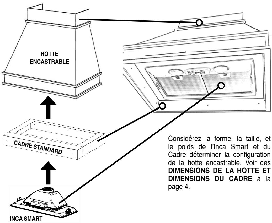
Create a perfectly-sealed, non-combustible perimeter around the Inca Smart. Depth adjustable from 16" - 17 7/8".
Standard Liner 30 Stainless - part # 620000304
Standard Liner 36 Stainless - part # 620000305
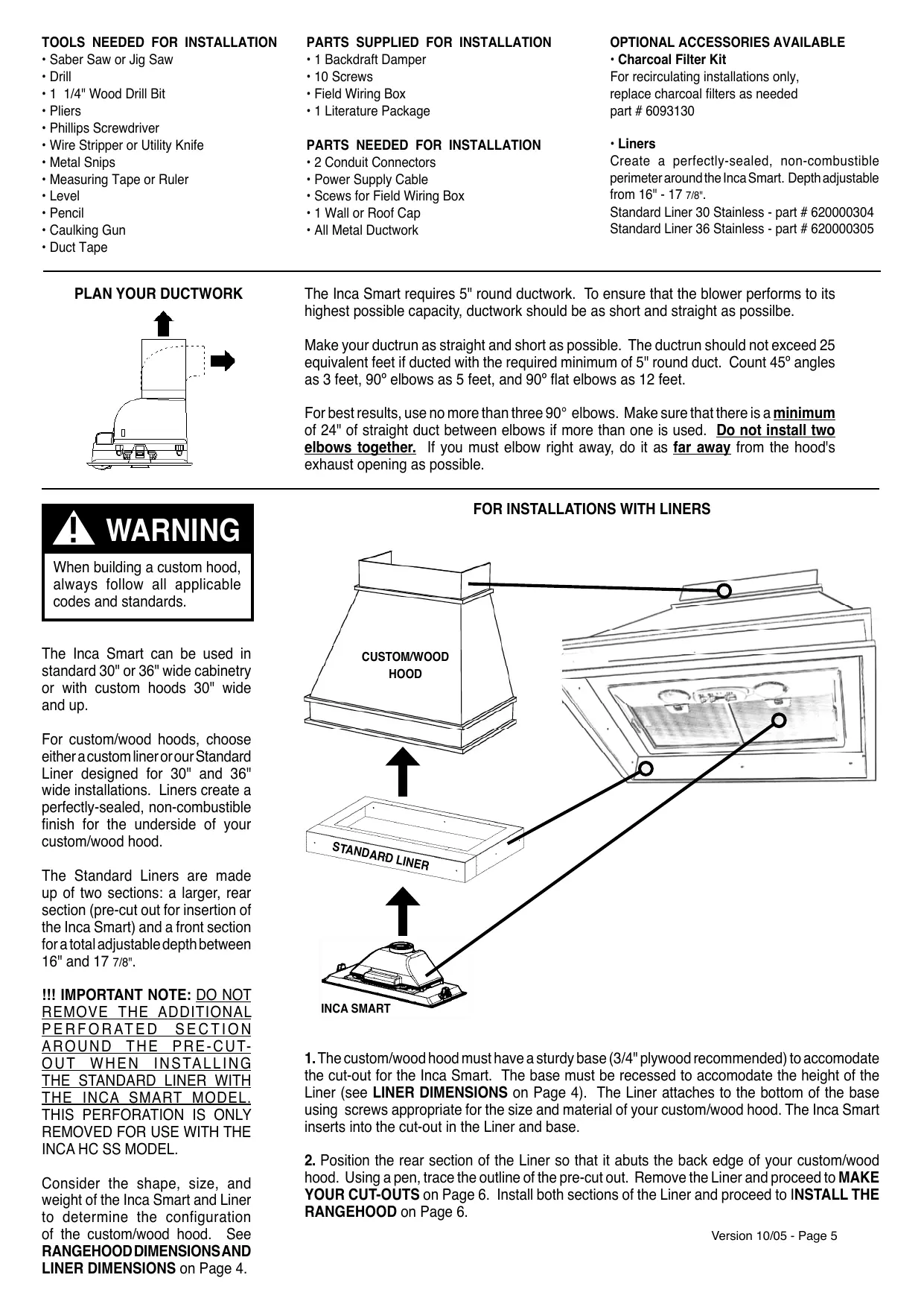
PLAN YOUR DUCTWORK
The Inca Smart requires 5" round ductwork. To ensure that the blower performs to its highest possible capacity, ductwork should be as short and straight as possilbe.
Make your ductrun as straight and short as possible. The ductrun should not exceed 25 equivalent feet if ducted with the required minimum of 5^ round duct. Count 45^ angles as 3 feet, 90^ elbows as 5 feet, and 90^ flat elbows as 12 feet.
For best results, use no more than three 90^ elbows. Make sure that there is a minimum of 24^ of straight duct between elbows if more than one is used. Do not install two elbows together. If you must elbow right away, do it as far away from the hood's exhaust opening as possible.

WARNING
When building a custom hood, always follow all applicable codes and standards.
The Inca Smart can be used in standard 30" or 36" wide cabinetry or with custom hoods 30" wide and up.
For custom/wood hoods, choose either a custom liner or our Standard Liner designed for 30'' and 36'' wide installations. Liners create a perfectly-sealed, non-combustible finish for the underside of your custom/wood hood.
The Standard Liners are made up of two sections: a larger, rear section (pre-cut out for insertion of the Inca Smart) and a front section for a total adjustable depth between 16" and 17 7/8".
!!! IMPORTANT NOTE: DO NOT REMOVE THE ADDITIONAL PERFORATED SECTION AROUND THE PRE-CUT-OUT WHEN INSTALLING THE STANDARD LINER WITH THE INCA SMART MODEL. THIS PERFORATION IS ONLY REMOVED FOR USE WITH THE INCA HC SS MODEL.
Consider the shape, size, and weight of the Inca Smart and Liner to determine the configuration of the custom/wood hood. See RANGEHOOD DIMENSIONSAND LINER DIMENSIONS on Page 4.
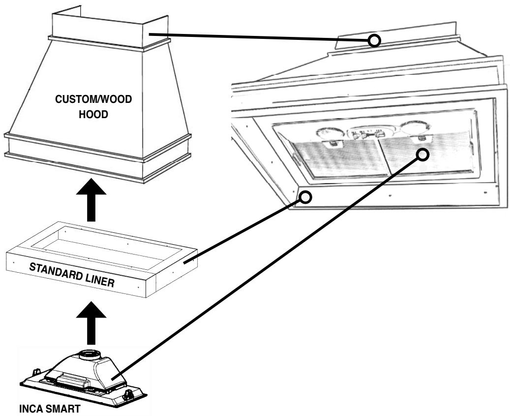
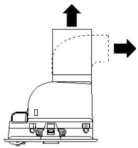
FOR INSTALLATIONS WITH LINERS
-
The custom/wood hood must have a sturdy base (3/4" plywood recommended) to accommodate the cut-out for the Inca Smart. The base must be recessed to accommodate the height of the Liner (see LINER DIMENSIONS on Page 4). The Liner attaches to the bottom of the base using screws appropriate for the size and material of your custom/wood hood. The Inca Smart inserts into the cut-out in the Liner and base.
-
Position the rear section of the Liner so that it abuts the back edge of your custom/wood hood. Using a pen, trace the outline of the pre-cut out. Remove the Liner and proceed to MAKE YOUR CUT-OUTS on Page 6. Install both sections of the Liner and proceed to INSTALL THE RANGEHOOD on Page 6.
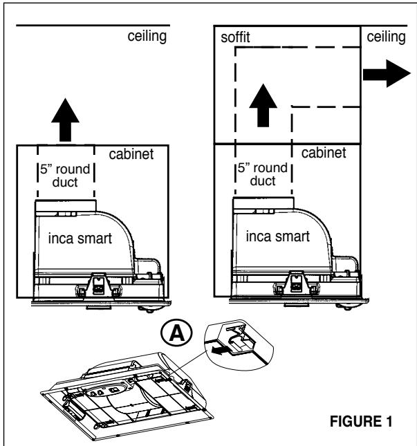
RECIRCULATING INSTALLATIONS
For recirculating installations (FIGURE 1), Charcoal Filters are necessary. The charcoal filters must be inserted behind the grease filters as indicated in (A in FIGURE 1). Recirculating installations also require some duct work to divert the air out of the cabinet. The duct work must not terminate inside the cabinet.
MAKE YOUR CUT-OUTS
- Disconnect and move freestanding range from cabinet opening to provide easier access to upper cabinet and rear wall. Put a thick, protective covering over cooktop, set-in range or countertop to protect from damage or dirt.
- Determine and clearly mark with a pencil the center line on the cabinet where the rangehood will be installed.
- Determine and make all necessary cuts in the wall for the ductwork. Install the ductwork before the rangehood.
- Determine the proper location for the Power Supply Cable. Use a 1 1/4'' Drill Bit to make this hole. Install the cable. Use caulking to seal around the hole. DO NOT turn on the power until installation is complete.
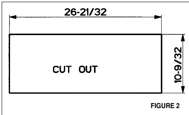
- Make the cut-out opening where the rangehood will be installed (FIGURE 2).
INSTALL THE RANGEHOOD
- Remove the rangehood from the carton and place on a flat surface. Cover the surface to prevent accidental damage. Remove all parts including the backdraft damper, screws, field wiring box and literature package before discarding the carton.
- Place the round damper into the exhaust opening of the rangehood and press down.
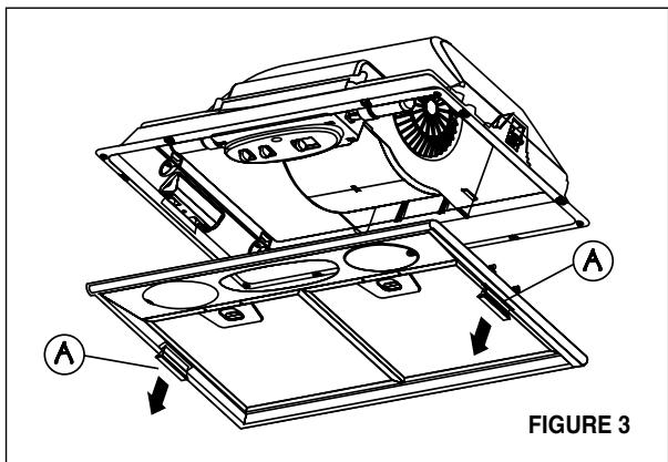
- Remove the bottom of the rangehood by pulling on the grey tabs (A in FIGURE 3) located on either side.
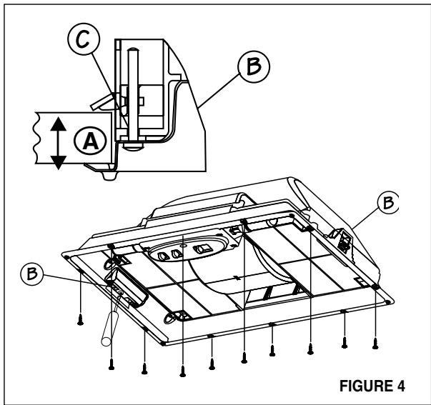
- Fix the rangehood to the cabinet using the two spring loaded brackets, one on each side of the rangehood (B in FIGURE 4). Using a philips screwdriver, tighten the adjustment screw (C in FIGURE 4) until the brackets adhere tightly to the surface. For thicknesses of LESS than 3/4 , insert a block of wood to fill in the gap between the cabinet bottom and the spring loaded bracket.
- IMPORTANT: Also fix the rangehood to the cabinet using the 10 screws provided (FIGURE 4).
- Replace the bottom of the rangehood and secure by pushing in the grey tabs (A in FIGURE 3).
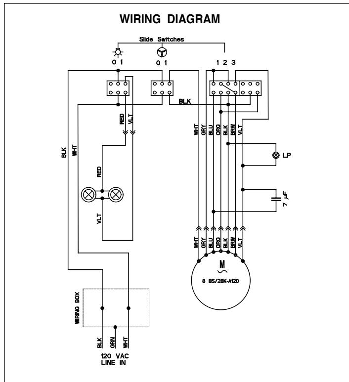
- Remove the cover from the field wiring compartment with a phillips screwdriver. Feed the Power Supply Cable through the electrical knockout. Connect the Power Supply Cable to the rangehood cable. Attach the White lead of the power supply to the White lead of the rangehood with a twist-on type wire connector. Attach the Black lead of the power supply to the Black lead of the rangehood with a twist-on type wire connector. Attach the Power Supply Cable grounding lead to the green screw provided. Using the 4 holes provided screw the field wiring compartment to the wall or cabinet as dictated by your Power Supply Cable location (screws not provided). Replace the cover.
- Connect the ductwork to the damper and seal all connections with duct tape.
- Turn the power supply on. Turn on the blower and light. If the rangehood does not operate, check that the circuit breaker is not tripped or the house fuse blown. If the unit still does not operate, disconnect the power supply and check that the wiring connections have been made properly.
USE AND CARE INFORMATION
This rangehood system is designed to remove smoke, cooking vapors and odors from the cooktop area.
Rangehood Control Panel
The control panel is located under the canopy. The position and function of each control button is indicated in FIGURE 5.
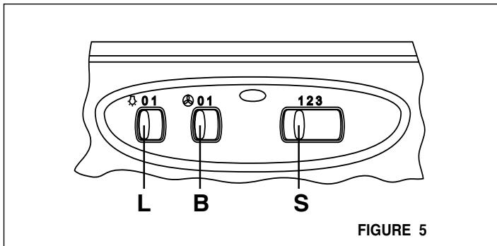
Light On/Off Button ( L )
On/Off switch for the incandescent light. Move the switch to "1" to turn the light ON and to "0" to turn it OFF.
Blower On/Off Button (B)
On/Off switch for the blower. Move the switch to "1" to turn the blower ON and to "0" to turn it OFF.
Blower Speed Button ( S )
Set the blower speed control to "1" for LOW speed, "2" for MEDIUM speed and "3" for HIGH speed.
For Best Results
Start the rangehood several minutes before cooking to develop proper airflow. Allow the unit to operate for several minutes after cooking is complete to clear all smoke and odors from the kitchen.
Cleaning
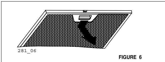
The metal grease filters should be cleaned frequently in hot detergent solution or washed in the dishwasher. The grease filters are removed by pressing the handle of the filter as indicated in FIGURE 6. When replacing, make sure that the filters are properly positioned with the handles in front and visible.
Clean exterior surfaces with hot soapy water. Abrasives and scouring agents can scratch rangehood finishes and should not be used to clean finished surfaces.
Replacing the Incandescent Lights
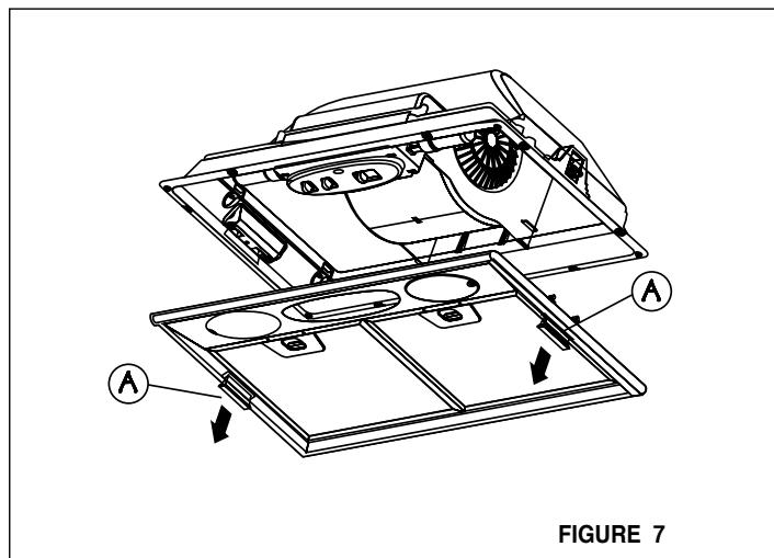
To replace the incandescent lights, first remove the entire bottom frame by pulling out the handles (A in FIGURE 7). Unscrew the two bulbs and replace.
WARRANTY & SERVICE
All Faber products are warranted against any defect in materials or workmanship for the original purchaser for a period of 1 year from the date of original purchase. This warranty covers labor and replacement parts. The warranty does not cover consumable parts such as filters and light bulbs. This warranty does not apply if this product has been subjected to faulty installation, misuse, or neglect. This warranty excludes any consequential expense or damage resulting from any use or malfunction of the product. All implied warranties are limited to the duration of this warranty.
To obtain warranty service, contact the dealer from whom you purchased the rangehood, or the local Faber distributor. If you cannot identify a local Faber distributor, contact us at (508) 358-5353 for the name of a distributor in your area.
- This rangehood uses two 40W incandescent bulbs.
OUTILS NÉCESSAIRES À L'INSTALLATION
16^ - 17 7/8" prof. adjustable
Cadre Standard 30 - part # 620000304
Cadre Standard 36 - part # 620000305
PLAN DU CONDUIT
Coude 45^ 3,0 pi
Coude 90^ 5,0 pi
Coude plat 90° 12,0 pi
Capuchon demur 0,0pi

AVERTISSEMENT
INSTALLATIONS AVEC CADRES
- READ AND SAVE THESE INSTRUCTIONS
- READ THESE INSTRUCTIONS BEFORE YOU START INSTALLING THIS RANGEHOOD
- LISEZ BIEN CETTE FICHE AVANT D'INSTALLER LA HOTTE
- WARNING
- ELECTRICAL REQUIREMENTS
- RÉGLEMENTS D'ÉVACUATION
- PARTS SUPPLIED FOR INSTALLATION
- PARTS NEEDED FOR INSTALLATION
- OPTIONAL ACCESSORIES AVAILABLE
- RECIRCULATING INSTALLATIONS
- MAKE YOUR CUT-OUTS
- INSTALL THE RANGEHOOD
- USE AND CARE INFORMATION
- Rangehood Control Panel
- Light On/Off Button ( L )
- Blower On/Off Button (B)
- Blower Speed Button ( S )
- For Best Results
- Cleaning
- Replacing the Incandescent Lights
- WARRANTY & SERVICE
- OUTILS NÉCESSAIRES À L'INSTALLATION
- AVERTISSEMENT
Brand : FABER
Model : INCA LUX - INCA SMART - INKA PLUS HC
Category : Kitchen hood