
Stilux EG8 X/V A90 Logic - 110.0255.547 - 1100255547 - Kitchen hood FABER - Free user manual and instructions
Find the device manual for free Stilux EG8 X/V A90 Logic - 110.0255.547 - 1100255547 FABER in PDF.
| Product type | Kitchen hood |
| Brand | Stilux (FABER) |
| Model | EG8 X/V A90 Logic |
| Reference | 110.0255.547 / 1100255547 |
| Width | 90 cm (estimate based on reference A90) |
| Installation type | Telescopic chimney, ducted or recirculating version |
| Power supply | 230 V, class I (grounding required) |
| Number of speeds | 3 speeds + timed intensive (6 min) |
| Lighting | LED (replacement by after-sales service) |
| Timer | Delayed shut-off of 30 minutes |
| Minimum distance above cooking surface | 650 mm |
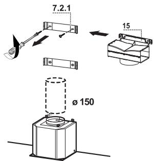
| Air outlet diameter | 150 mm or 120 mm with reducer |
| Grease filters | Metallic, dishwasher safe, every 2 months |
| Charcoal filter | Active, non-washable, replace every 4 months |
| Chimney material | Metal (not specified) |
| Controls | Push buttons with indicator lights |
| Weight | Not specified |
| Provided documents | Instruction manual |
Frequently Asked Questions - Stilux EG8 X/V A90 Logic - 110.0255.547 - 1100255547 FABER
User questions about Stilux EG8 X/V A90 Logic - 110.0255.547 - 1100255547 FABER
0 question about this device. Answer the ones you know or ask your own.
Ask a new question about this device
Download the instructions for your Kitchen hood in PDF format for free! Find your manual Stilux EG8 X/V A90 Logic - 110.0255.547 - 1100255547 - FABER and take your electronic device back in hand. On this page are published all the documents necessary for the use of your device. Stilux EG8 X/V A90 Logic - 110.0255.547 - 1100255547 by FABER.
USER MANUAL Stilux EG8 X/V A90 Logic - 110.0255.547 - 1100255547 FABER
CARE AND CLEANING 13
SOMMAIRE
FR
CONSIGNES DE SECURITE 14
CHARACTERISTIQUES 17
INSTALLATION 19
UTILISATION 22
NETTOYAGE ET ENTRETIEN 23
INHALTSVERZEICHNIS
DE
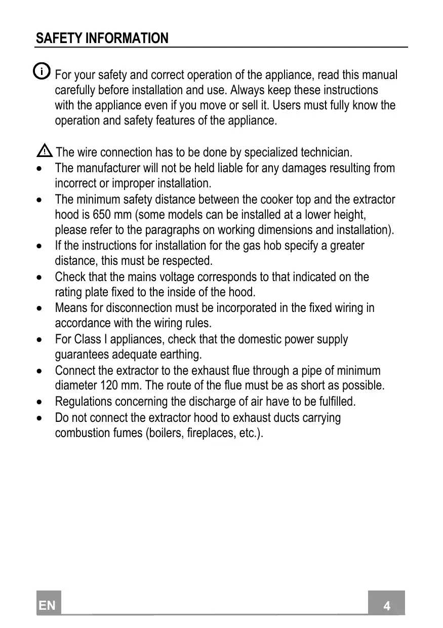
For your safety and correct operation of the appliance, read this manual carefully before installation and use. Always keep these instructions with the appliance even if you move or sell it. Users must fully know the operation and safety features of the appliance.

The wire connection has to be done by specialized technician.
- The manufacturer will not be held liable for any damages resulting from incorrect or improper installation.
- The minimum safety distance between the cooker top and the extractor hood is 650~mm (some models can be installed at a lower height, please refer to the paragraphs on working dimensions and installation).
- If the instructions for installation for the gas hob specify a greater distance, this must be respected.
- Check that the mains voltage corresponds to that indicated on the rating plate fixed to the inside of the hood.
- Means for disconnection must be incorporated in the fixed wiring in accordance with the wiring rules.
- For Class I appliances, check that the domestic power supply guarantees adequate earthing.
- Connect the extractor to the exhaust flue through a pipe of minimum diameter 120 ~mm . The route of the flue must be as short as possible.
- Regulations concerning the discharge of air have to be fulfilled.
-
Do not connect the extractor hood to exhaust ducts carrying combustion fumes (boilers, fireplaces, etc.).
-
If the extractor is used in conjunction with non-electrical appliances (e.g. gas burning appliances), a sufficient degree of aeration must be guaranteed in the room in order to prevent the backflow of exhaust gas. When the cooker hood is used in conjunction with appliances supplied with energy other than electric, the negative pressure in the room must not exceed 0,04 mbar to prevent fumes being drawn back into the room by the cooker hood.
- The air must not be discharged into a flue that is used for exhausting fumes from appliances burning gas or other fuels.
- If the supply cord is damaged, it must be replaced from the manufacturer or its service agent.
- Connect the plug to a socket complying with current regulations, located in an accessible place.
- With regards to the technical and safety measures to be adopted for fume discharging it is important to closely follow the regulations provided by the local authorities.
WARNING: Before installing the Hood, remove the protective films. - Use only screws and small parts in support of the hood.
WARNING: Failure to install the screws or fixing device in accordance with these instructions may result in electrical hazards. - Do not look directly at the light through optical devices (binoculars, magnifying glasses...).
- Do not flambé under the range hood; risk of fire.
- This appliance can be used by children aged from 8 years and above and persons with reduced physical, sensory or mental capabilities or lack of experience and knowledge if they have been given supervision or instruction concerning use of the appliance in a safe way and understand the hazards involved. Children shall not play with the appliance. Cleaning and user maintenance shall not be made by children without supervision.
-
Children should be supervised to ensure that they do not play with the appliance.
-
The appliance is not to be used by persons (including children) with reduced physical, sensory or mental capabilities, or lack of experience and knowledge, unless they have been given supervision or instruction.
Accessible parts may become hot when used with cooking appliances. - Clean and/or replace the Filters after the specified time period (Fire hazard). See paragraph Care and Cleaning.
- There shall be adequate ventilation of the room when the range hood is used at the same time as appliances burning gas or other fuels (not applicable to appliances that only discharge the air back into the room).
- The symbol on the product or on its packaging indicates that this product may not be treated as household waste. Instead it shall be handed over to the applicable collection point for the recycling of electrical and electronic equipment. By ensuring this product is disposed of correctly, you will help prevent potential negative consequences for the environment and human health, which could otherwise be caused by inappropriate waste handling of this product. For more detailed information about recycling of this product, please contact your local city office, your household waste disposal service or the shop where you purchased the product.
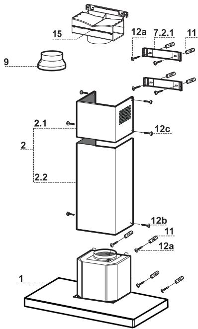
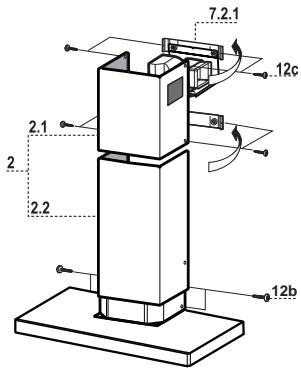
Components
| Ref. | Q.ty | Product Components |
| 1 | 1 | Hood Body, complete with: Controls, Light, Blower, Filters |
| 2 | 1 | Telescopic Chimney comprising: |
| 2.1 | 1 | Upper Section |
| 2.2 | 1 | Lower Section |
| 9 | 1 | Reducer Flangeø 150-120 mm |
| 15 | 1 | Air Outlet Connection |
| Ref. | Q.ty | Installation Components |
| 7.2.1 | 2 | Upper Chimney Section Fixing Brackets |
| 11 | 8 | Wall Plugs |
| 12a | 8 | Screws 4,2 x 44,4 |
| 12c | 6 | Screws 2,9 x 9,5 |
| Q.ty | Documentation | |
| 1 | Instruction Manual |
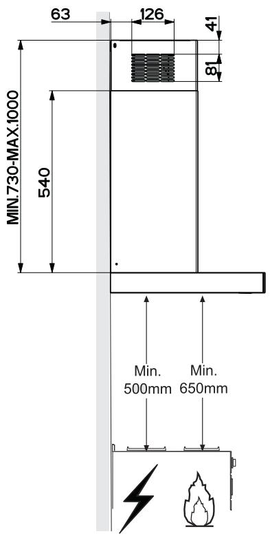
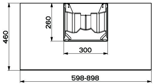
Wall drilling and bracket fixing
Wall marking:
- Draw a vertical line on the supporting wall up to the ceiling, or as high as practical, at the centre of the area in which the hood will be installed.
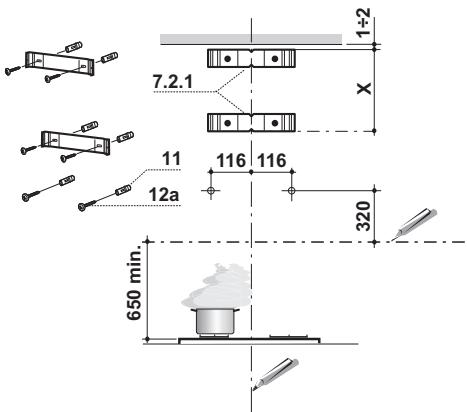
- Draw a horizontal line at 650mm above the hob. Place bracket 7.2.1 on the wall as shown about 1 - 2mm from the ceiling or upper limit aligning the centre (notch) with the vertical reference line.
- Mark the wall at the centres of the holes in the bracket.
- Place bracket 7.2.1 on the wall as shown at X mm below the first bracket ( X = height of the upper chimney section supplied), aligning the centre (notch) with the vertical line.
- Mark the wall at the centres of the holes in the bracket.
- Mark a reference point as indicated at 116mm from the vertical reference line and 320mm above the horizontal reference line.
- Repeat this operation on the other side.
- Drill 8 mm holes at all the centre points marked.
- Insert the wall plugs 11 in the holes.
Fix the brackets using the 12a (4,2× 44,4) screws supplied. -
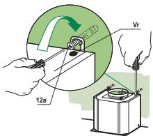
Insert the two screws 12a (4,2 x 44,4) supplied in the hood body fixing holes, leaving a gap of 5 - 6mm between the wall and the head of the screw.
-
Before attaching the hood body, tighten the two screws Vr located on the hood body mounting points.
- Hook the hood body onto the screws 12a.
- Fully tighten support screws 12a.
- Adjust screws Vr to level the hood body.
- If necessary, it is possible to fasten the hood to the wall using more screws with wall plugs, which can be positioned from inside the hood canopy.
Connections
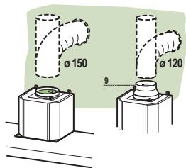
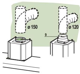
DUCTED VERSION AIR EXHAUST SYSTEM
When installing the ducted version, connect the hood to the chimney using either a flexible or rigid pipe 150 or 120~mm the choice of which is left to the installer.
- To install a 0.120 ~mm air exhaust connection, insert the reducer flange 9 on the hood body outlet.
Fix the pipe in position using sufficient pipe clamps (not supplied). - Remove possible charcoal filters.
AIR OUTLET - RECIRCULATION VERSION
- Unfasten the 2 screws fixing the upper bracket 7.2.1.
- Fasten the air outlet connector 15 in its place, using the 2 screws removed as above.
- Join the Connector 15 to the Hood canopy outlet using a rigid or flexible pipe 150mm , selection of which is at the discretion of the installation technician.
- Make sure that the Activated charcoal odour filter has been fitted.
ELECTRICAL CONNECTION
- Connect the hood to the mains through a two-pole switch having a contact gap of at least 3mm .
- Remove the grease filters (see paragraph Maintenance) being sure that the connector of the feeding cable is correctly inserted in the socket placed on the side of the fan.
Flue assembly
Upper exhaust flue
- Slightly widen the two sides of the upper flue and hook them behind the brackets 7.2.1, making sure that they are well seated.
- Secure the sides to the brackets by using the 4 screws 12c (2,9 x 9,5) supplied.
- Make sure that the outlet of the extensions pieces is aligned with the chimney outlets.
Lower exhaust flue
- Slightly widen the two sides of the flue and hook them between the upper flue and the wall, making sure that they are well seated.
Fix the lower part laterally to the hood body by using the 2 screws 12c (2,9 x 9,5) supplied.

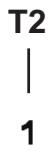
Control panel


| Button | Function | |
| T1 | Turns the Motor off. | - |
| T2 | Turns the motor on at speed one | Buttons T1+T2 are on. |
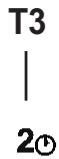
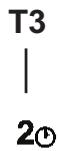
| T3 | Turns the Motor on at speed two | Buttons T1+T3 are on. |
| Press and hold for 2 seconds to enable shutdown with a 30 minute delay (Mo-tor+Lights). It is possible to change the operating speed when this function is enabled. | The respective buttons T1+ (T2 or T3 or T4) will flash. | |
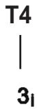
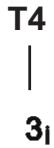
| T4 | Turns the Motor on at speed three | Buttons T1+T4 are on. |
| Press and hold for 2 seconds to activate Intensive speed, which is timed to run for 6 minutes. At the end of this time it will automatically return to the speed set before. Suitable to deal with maximum levels of cooking fumes. | The button flashes. | |
| L | Turns the Lighting System on and off at maximum intensity. | Button on |
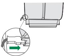
Grease filters
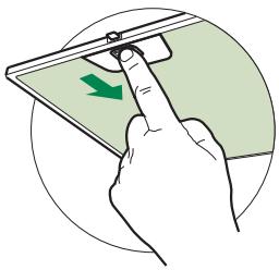
CLEANING METAL SELF- SUPPORTING GREASE FILTERS
- The filters must be cleaned every 2 months of operation, or more frequently for particularly heavy usage, and can be washed in a dishwasher.
- Remove the filters one at a time by pushing them towards the back of the group and pulling down at the same time.
- Wash the filters, taking care not to bend them. Allow them to dry before refitting.
- When refitting the filters, make sure that the handle is visible on the outside.
Activated charcoal filter (Recirculation version)
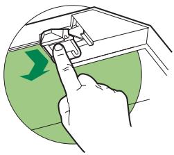
REPLACING THE ACTIVATED CHARCOAL FILTER
- The filter is not washable and cannot be regenerated, and must be replaced approximately every 4 months of operation, or more frequently for particularly heavy usage.
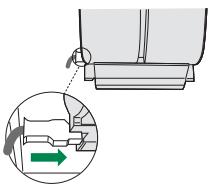
- Remove the metal grease filters.
- Remove the saturated activated carbon filter by releasing the fixing hooks.
- Fit the new filter by hooking it into its seating.
- Refit the metal grease filters.
Lighting unit
- For replacement contact technical support ("To purchase contact technical support").
①
BbIpyCK BO3dYxA N3 BCACbIBAIOUe BbITJXKN
Дя установки BCасьыб IOОЕ BВТЯЖК COEOHNHTb ee C BblIyckHOH trpy60ж ecTKOи HIN Г6KOJ trpy6KоДнametpOM 150 HIN 120 MM, TIII KOTopoM MOKET Bbl6paTb MOHTaXHHK.
-ДИА COEДINHEHINI TpyKoi O 120 MM BCTaBnIb IepeXoIHbI ΦIaHeI 9В BbIyCKHO OEIBepCTHe KOpIyCa BbIYkN.
3aKpeINb Tpy6ky COOTBeTCTByIOHMM Tpy6HbIM 3aKHMAM. Heo6xOINMb KpeIeKHB MaTePnaJI He BXoINT B KOMIIJEKT.
- BbHytB ΦHJIbTpbl OT 3aIIaxOB Ha aKTHBHOM yTJIe.
BbIpyCK BO3dYXA B PEXIMME ΦNJIbTPALIN
Pa3BHTHTe 2 BnHTa KpeIIeHHa BepxHecko6bI 7.2.1.
Ha ee MeCTO IIpHBnHTInTe BbIpyCKHoi IaTpy60K Bo3dyxa 15 c IIOMOIIbIO 2 ChrTbIX BnHTOB.
- CoeHHHTe IIaTp6ok 15 c BbIyucKbIM OTBepCTHeM B KOpIyce BbITJxKKn JKeCTKOII INI rH6KO Tpy6KO (IO yCMOTpeHHO MOHTaXHHka) dHaMeTpOM 150 MM.
-Поберъп Нлчне Фньтра Пргв 3аiaxOB Ha aKTHBnpoBaHHOM yTJIe.

3JIeKTPnueCKOEIOKJIIOUeHNE
CoeHHHTb BbITKky c ceTeBBIM HAnpJKeHHeM, yCTaHOBHB IByXIOJIIOCHbIyIKJIIOVAteJIb Cpa3BeJeHHem KOHTaKTOB He MeHee 3 MM.
CHTB IPOTHBOXKHPOBBE HJIbTpbi (CMOTpn pa3JeJ "YxoJ") H IIPOBepHTB IpaBHJIbHOCTb IOJOKeHn pa3bema IITaIOIeRO Ka6eJI B PO3ETKE BbITKaKN
YcTaHOBKa DbIMOXOda
BepxHHn IbIMoXoI
CJIeKa pa3BecTH nIbe 6OKOBbIe KpOMKn IbIMOxOJa, 3aIeIHtB Hx 3a cKObI 7.2.1 H BHOb CBecTH IO yIOpa.
3aKpeIHTb IbIMOXoI c6Oky 4 BXOJIHMMB KOMIIJEKT BHNTaMn 12c (2,9x9,5).
- IIpoBepHTb, YTO6bI BbIIyckHoe OTBepCThe HacaIOK IaTpy6Ka COBIIaJIO c peIeTkaMn IbIMOXOJa.
HnKnnIbIMOXoJ
CJIeKka pa3BecTH IBe 6OKOBbIe KpOMKn IbIMOXOJa, 3aIeIHt b Hx MeJy BepXHm IbIMOXOJOM N CTeHOH IN BHOBcCBCTN IO yIopa.
3aKpeINITb HNKHIOU qactb IbIMOXoJa c6Oky K KopIpy BblTJKKBNXODIINMH B KOMIIJEKT 2 BHHTAMH 12c (2,9 x 9,5).
Panaelb ynpablenia


- SOMMAIRE
- FR
- INHALTSVERZEICHNIS
- DE
- Wall drilling and bracket fixing
- Wall marking:
- Connections
- DUCTED VERSION AIR EXHAUST SYSTEM
- AIR OUTLET - RECIRCULATION VERSION
- ELECTRICAL CONNECTION
- Flue assembly
- Upper exhaust flue
- Lower exhaust flue
- Control panel
- Grease filters
- CLEANING METAL SELF- SUPPORTING GREASE FILTERS
- Activated charcoal filter (Recirculation version)
- REPLACING THE ACTIVATED CHARCOAL FILTER
- Lighting unit
- BbIpyCK BO3dYxA N3 BCACbIBAIOUe BbITJXKN
- BbIpyCK BO3dYXA B PEXIMME ΦNJIbTPALIN
- 3JIeKTPnueCKOEIOKJIIOUeHNE
- YcTaHOBKa DbIMOXOda
- BepxHHn IbIMoXoI
- HnKnnIbIMOXoJ
- Panaelb ynpablenia
Brand : FABER
Model : Stilux EG8 X/V A90 Logic - 110.0255.547 - 1100255547
Category : Kitchen hood