
FFI622GR - Sink FRANKE - Free user manual and instructions
Find the device manual for free FFI622GR FRANKE in PDF.
| Product type | Decorative extractor hood |
| Brand | Franke |
| Model | FFI622GR |
| Use | Domestic, kitchen odor removal |
| Adjustable depth | 275 to 360 mm |
| Power supply | 220-240 V, 50/60 Hz (estimate) |
| Energy efficiency class | Not specified (estimated B) |
| Noise level | Variable by speed (estimated 50-65 dB) |
| Extraction diameter | 120 or 150 mm |
| Number of speeds | 3 (minimum, medium, maximum) |
| Lighting | Integrated, on/off control |
| Filter type | Washable anti-grease metal + activated carbon (optional) |
| Grease filter maintenance | Every 2 months, dishwasher-safe |
| Carbon filter replacement | Every 4 months (non-washable) |
| Installation | Extraction or recirculation version (carbon filter required) |
| Minimum distance from cooking surface | 650 mm (unless specific instructions) |
| Electrical class | I (earthed) |
| Materials | Metal, glass (estimated) |
| Control | Mechanical sliders for lighting and motor |
| Weight | Not specified (estimated 15-20 kg) |
Frequently Asked Questions - FFI622GR FRANKE
User questions about FFI622GR FRANKE
0 question about this device. Answer the ones you know or ask your own.
Ask a new question about this device
Download the instructions for your Sink in PDF format for free! Find your manual FFI622GR - FRANKE and take your electronic device back in hand. On this page are published all the documents necessary for the use of your device. FFI622GR by FRANKE.
USER MANUAL FFI622GR FRANKE
RECOMMENDATIONS AND SUGGESTIONS 11
CHARACTERISTICS 14
INSTALLATION....15
USE 17
MAINTENANCE 18
SOMMAIRE
FR
CONSEILS ET SUGGESTIONS....19
CARACTERISTIQUES....22
INSTALLATION....23
UTILISATION 25
ENTRETIEN 26
INHALTSVERZEICHNIS
DE
natural_image
Illustration of a chemical experiment setup with a conical flask, thermometer, and smokestack (no text or symbols)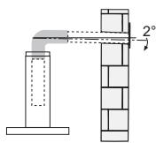
natural_image
Diagram of a pipe connection with a 2° angle indicator, showing structural components without any text or symbols.natural_image
Illustration of a cooking setup with a stove, a steaming pot, and a fire plume (no text or symbols)natural_image
Technical illustration of a mechanical device with exploded view and internal components (no text or symbols)FISSAGGIO AL MURO
natural_image
Pure technical diagram showing a mechanical assembly with no text, numbers, or symbolsConnessioni
USCITA ARIA VERSIONE ASPIRANTE
natural_image
Diagram showing a mechanical component with a highlighted section and directional arrow (no text or symbols)Quadro comandi

natural_image
Illustration of a hand holding a smartphone with a green arrow pointing to the screen (no text or symbols)natural_image
Diagram of two mechanical components labeled A and B with green directional arrows indicating rotation or movement (no text or symbols beyond labels)Illuminazione
The Instructions for Use apply to several versions of this appliance. Accordingly, you may find descriptions of individual features that do not apply to your specific appliance.
INSTALLATION
- The manufacturer will not be held liable for any damages resulting from incorrect or improper installation.
- The minimum safety distance between the cooker top and the extractor hood is 650 mm (some models can be installed at a lower height, please refer to the paragraphs on working dimensions and installation).
- Check that the mains voltage corresponds to that indicated on the rating plate fixed to the inside of the hood.
- For Class I appliances, check that the domestic power supply guarantees adequate earthing.
Connect the extractor to the exhaust flue through a pipe of minimum diameter 120 mm. The route of the flue must be as short as possible.
- Do not connect the extractor hood to exhaust ducts carrying combustion fumes (boilers, fireplaces, etc.).
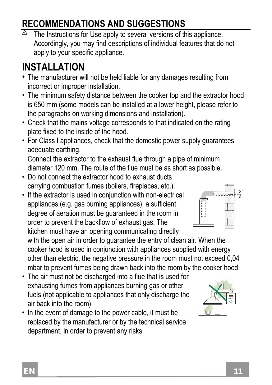
- If the extractor is used in conjunction with non-electrical appliances (e.g. gas burning appliances), a sufficient degree of aeration must be guaranteed in the room in order to prevent the backflow of exhaust gas. The kitchen must have an opening communicating directly
with the open air in order to guarantee the entry of clean air. When the cooker hood is used in conjunction with appliances supplied with energy other than electric, the negative pressure in the room must not exceed 0,04 mbar to prevent fumes being drawn back into the room by the cooker hood.
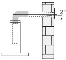
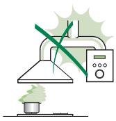
- The air must not be discharged into a flue that is used for exhausting fumes from appliances burning gas or other fuels (not applicable to appliances that only discharge the air back into the room).
- In the event of damage to the power cable, it must be replaced by the manufacturer or by the technical service department, in order to prevent any risks.
natural_image
Illustration of a chemical experiment setup with a conical flask, thermometer, and smokestack (no text or symbols)- If the instructions for installation for the gas hob specify a greater distance specified above, this has to be taken into account. Regulations concerning the discharge of air have to be fulfilled.
- Use only screws and small parts in support of the hood.
Warning: Failure to install the screws or fixing device in accordance with these instructions may result in electrical hazards.
- Connect the hood to the mains through a two-pole switch having a contact gap of at least 3 mm.
USE
- The extractor hood has been designed exclusively for domestic use to eliminate kitchen smells.
- Never use the hood for purposes other than for which it has been designed.
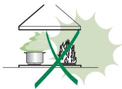
- Never leave high naked flames under the hood when it is in operation.
- Adjust the flame intensity to direct it onto the bottom of the pan only, making sure that it does not engulf the sides.
- Deep fat fryers must be continuously monitored during use: overheated oil can burst into flames.
- Do not flambè under the range hood; risk of fire.
- This appliance can be used by children aged from 8 years and above and persons with reduced physical, sensory or mental capabilities or lack of
natural_image
Illustration of a cooking setup with a pot and stove, featuring a crossed green pan and smoke (no text or symbols)experience and knowledge if they have been given supervision or instruction concerning use of the appliance in a safe way and understand the hazards involved. Children shall not play with the appliance. Cleaning and user maintenance shall not be made by children without supervision.
- This appliance is not intended for use by persons (including children) with reduced physical, sensory or mental capabilities, or lack of experience and knowledge, unless they have been given supervision or instruction concerning use of the appliance by a person responsible for their safety.
- “CAUTION: Accessible parts may become hot when used with cooking appliances.”
MAINTENANCE
- Switch off or unplug the appliance from the mains supply before carrying out any maintenance work.
- Clean and/or replace the Filters after the specified time period (Fire hazard).
- The Grease filters must be cleaned every 2 months of operation, or more frequently for particularly heavy usage, and can be washed in a dishwasher.
- The Activated charcoal filter is not washable and cannot be regenerated, and must be replaced approximately every 4 months of operation, or more frequently for particularly heavy usage.
- "Failure to carry out cleaning as indicated will result in a fire hazard".
- Clean the hood using a damp cloth and a neutral liquid detergent.
The symbol ☒ on the product or on its packaging indicates that this product may not be treated as household waste. Instead it shall be handed over to the applicable collection point for the recycling of electrical and electronic equipment. By ensuring this product is disposed of correctly, you will help prevent potential negative consequences for the environment and human health, which could otherwise be caused by inappropriate waste handling of this product. For more detailed information about recycling of this product, please contact your local city office, your household waste disposal service or the shop where you purchased the product.
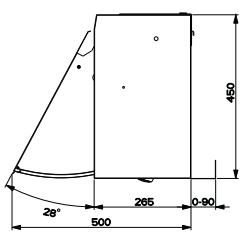
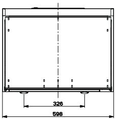
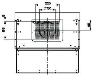
Dimensions
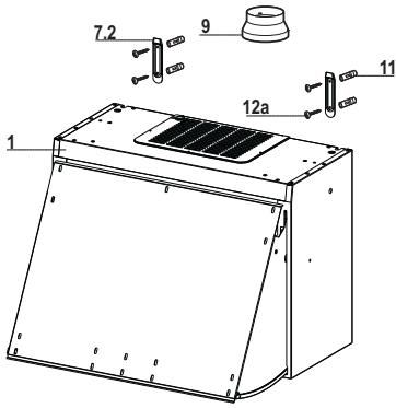
Components
| Ref. | Q.ty | Product Components |
| 1 | 1 | Hood Body, complete with :Controls, Light, Blower, Filters |
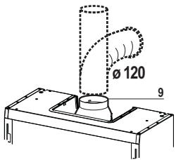
| 9 | 1 | Reducer Flange ø 150-120 mm |
| Ref. | Q.ty | Installation Components |
| 7.2 | 2 | Hood Body Fixing Brackets |
| 11 | 4 | Wall Plugs |
| 12a | 4 | Screws |
| Q.ty | Documentation |
| 1 | Instruction Manual |
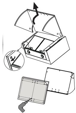
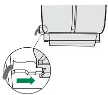
FIXING OF THE FRONTAL PANEL TO THE VISOR
- Pull out the metal visor and, at the same time, unlock the lever on the left side of the hood.
- Use the cardboard template when drilling the front panel. Fix the panel to the visor using the screws supplied.
natural_image
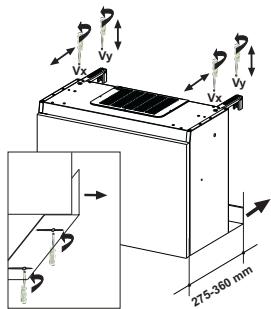
Technical illustration of a mechanical device with exploded view and internal components (no text or symbols)FIXING OF THE HOOD TO THE WALL
- Hood depth can vary from 275 to 360 mm .
- Regulate the Vx screws when adjusting the brackets to the right depth.
- When adjusting the lower part of the hood to the requested depth it is necessary to loose the screws of the metal distance piece and to move it as much as necessary.
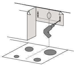
- Use the specific cardboard template when drilling the holes into the wall. Put the dowels into the holes and fix the two metal brackets using the four screws supplied together with other accessories.
- Use the specific cardboard template when drillig the side closets.
When the hood is used in ducting version it is necessary to remove the grid from the air outlet.
- Hang the hood on the metal brackets.
- Put back the visor again paying attention that the runners are put correctly into the proper places. Adjust the visor sliding by means of the two screws.
- Regulating the Vy screws it is possible to align the hood height compared to the closets.
- When necessary adjust again the hood depth.
natural_image
Pure technical diagram showing a mechanical assembly with no text, numbers, or symbolsConnections
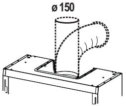
DUCTED VERSION AIR EXHAUST SYSTEM
When installing the ducted version, connect the hood to the chimney using either a flexible or rigid pipe 150 or 120 mm, the choice of which is left to the installer.
- To install a 120 mm air exhaust connection, insert the reducer flange 9 on the hood body outlet.
- Fix the pipe in position using sufficient pipe clamps (not supplied).
- Remove possible charcoal filters.
AIR OUTLET IN RECYCLING VERSION
- Make sure that the hood body has been completely fixed.
- Make sure that hood is equipped with charcoal filters.
ELECTRICAL CONNECTION
- Connect the hood to the mains through a two-pole switch having a contact gap of at least 3 mm.
- Remove the grease filters (see paragraph Maintenance) being sure that the connector of the feeding cable is correctly inserted in the socket placed on the side of the fan.
natural_image
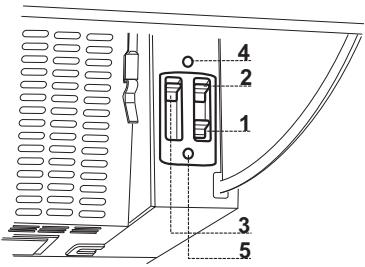
Diagram showing a mechanical component with a highlighted section and directional arrow (no text or symbols)Control board

| 1 | Lighting | On/off lighting system. |
| 2 | Motor | On/off motor. |
| 3 | Speed | Speed control: |
| 1. Minimum speed, particularly silent, continuous air exchange, suitable in presence of only few cooking vapours and odours. | ||
| 2. Medium speed, due to an optimum relation between hood extraction capacity and the noise level, it is suitable for most of the cooking conditions. | ||
| 3. Maximum speed, suitable for the cooking conditions when vapours and smells are of the utmost emission even for a longer time. |
OPTIONAL
| 4 | Microswitch | Microswitch, which is activated by the movement of the visor. It switches on and off the hood basing on the conditions which have been earlier established with the sliders of the control panel. |
| 5 | Led | Led indicating when the motor is on. |
Grease filters
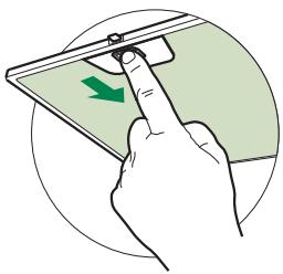
CLEANING METAL SELF- SUPPORTING GREASE FILTERS
- The filters must be cleaned every 2 months of operation, or more frequently for particularly heavy usage, and can be washed in a dishwasher.
- Remove the filters one at a time by pushing them towards the back of the group and pulling down at the same time.
- Wash the filters, taking care not to bend them. Allow them to dry before refitting.
- When refitting the filters, make sure that the handle is visible on the outside.
natural_image
Illustration of a hand holding a smartphone with a green arrow pointing to the screen (no text or symbols)Activated charcoal filter (Recirculation version)
These filters are not washable and cannot be regenerated, and must be replaced approximately every 4 months of operation, or more frequently with heavy usage.
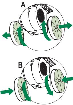
REPLACING THE ACTIVATED CHARCOAL FILTER
- Remove the metal grease filters
- Remove the saturated activated charcoal filter as shown (A).
• Fit the new filters (B). - Replace the metal grease filters.
natural_image
Diagram of two mechanical components labeled A and B with green arrows indicating rotational motion (no text or symbols present)Lighting unit
- For replacement contact technical support ("To purchase contact technical support").
natural_image
Illustration of a chemical experiment setup with a conical flask, thermometer, and smoke rising (no text or symbols)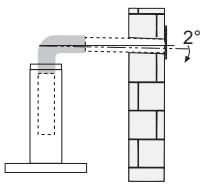
natural_image
Illustration of a cooking pot with green smoke rising from a stove, crossed by a green X (no text or symbols)natural_image
Technical illustration of a mechanical device with exploded view and assembly details (no text or symbols)FIXATION CONTRE LA PAROI
natural_image
Pure technical diagram showing a mechanical assembly with no text, numbers, or symbolsBranchements
SORTIE AIR VERSION ASPIRANTE
natural_image
Diagram showing a mechanical component with an inset view of a tool interacting with a green arrow (no text or symbols present)natural_image
Illustration of a hand pressing down on a smartphone screen with a green arrow indicating the scroll (no text or symbols present)Filtre anti-odeur (Version filtrante)
REPLACEMENT FILTRE AU CHARBON ACTIF
natural_image
Diagram of two mechanical components labeled A and B with green directional arrows indicating motion or force (no text or symbols beyond labels)Éclairage
natural_image
Illustration of a chemical experiment setup with a conical flask, thermometer, and smokestack (no text or symbols)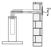
natural_image
Illustration of a cooking setup with a pot, stove, and steam rising (no text or symbols)natural_image
Technical illustration of a mechanical device with exploded view and internal components (no text or symbols)WANDBEFESTIGUNG
natural_image
Pure technical diagram showing a mechanical assembly with no text, numbers, or symbolsnatural_image
Diagram showing a mechanical component with an inset view of a tool interacting with a green arrow (no text or symbols present)Bedienfeld

natural_image
Illustration of a hand interacting with a smartphone screen showing a green arrow (no text or symbols present)natural_image
Diagram of a mechanical device with rotating wheels and green arrows indicating motion (no text or symbols)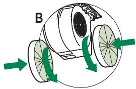
natural_image
Diagram of a mechanical device with rotating wheels and green directional arrows indicating motion (no text or symbols)Beleuchtung
LED-Strahler
natural_image
Illustration of a chemical experiment setup with a funnel, reaction flask, and control panel (no text or symbols)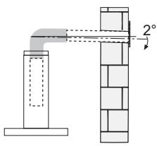
natural_image
Illustration of a cooking setup with a pot and stove, featuring a crossed green pan and smoke (no text or symbols)natural_image
Technical illustration of a mechanical device with exploded view and internal components (no text or symbols)DUVAR MONTAJ
natural_image
Pure technical diagram showing a mechanical assembly with no text, numbers, or symbolsBağlantılar
ASPIRATÖRLÜ MODEL HAVA ÇIKIŞI
natural_image
Diagram showing a mechanical component with a green arrow indicating direction, no text or symbols presentKumanda Tablosu
natural_image
Illustration of a hand holding a smartphone with a green arrow pointing to the screen (no text or symbols)Aktif karbonlu koku giderici filtreler (Filtreli Model)
natural_image
Diagram of two mechanical components labeled A and B with green directional arrows indicating rotation or movement (no text or symbols beyond labels)Aydınlatma
- SOMMAIRE
- INHALTSVERZEICHNIS
- FISSAGGIO AL MURO
- Connessioni
- USCITA ARIA VERSIONE ASPIRANTE
- Illuminazione
- INSTALLATION
- USE
- MAINTENANCE
- Dimensions
- FIXING OF THE FRONTAL PANEL TO THE VISOR
- FIXING OF THE HOOD TO THE WALL
- Connections
- DUCTED VERSION AIR EXHAUST SYSTEM
- AIR OUTLET IN RECYCLING VERSION
- ELECTRICAL CONNECTION
- Grease filters
- CLEANING METAL SELF- SUPPORTING GREASE FILTERS
- Activated charcoal filter (Recirculation version)
- REPLACING THE ACTIVATED CHARCOAL FILTER
- Lighting unit
- FIXATION CONTRE LA PAROI
- Branchements
- SORTIE AIR VERSION ASPIRANTE
- Filtre anti-odeur (Version filtrante)
- REPLACEMENT FILTRE AU CHARBON ACTIF
- Éclairage
- WANDBEFESTIGUNG
- Beleuchtung
- LED-Strahler
- DUVAR MONTAJ
- Bağlantılar
- ASPIRATÖRLÜ MODEL HAVA ÇIKIŞI
- Aktif karbonlu koku giderici filtreler (Filtreli Model)
- Aydınlatma
Brand : FRANKE
Model : FFI622GR
Category : Sink