
CHAUFFEO - Electric water heater ATLANTIC - Free user manual and instructions
Find the device manual for free CHAUFFEO ATLANTIC in PDF.
User questions about CHAUFFEO ATLANTIC
0 question about this device. Answer the ones you know or ask your own.
Ask a new question about this device
Download the instructions for your Electric water heater in PDF format for free! Find your manual CHAUFFEO - ATLANTIC and take your electronic device back in hand. On this page are published all the documents necessary for the use of your device. CHAUFFEO by ATLANTIC.
USER MANUAL CHAUFFEO ATLANTIC
Electric water heater
Elektrische boiler
CHAUFFEO CHAUFFEO+
Chauffe-eau vertical mural 9
Chauffe-eau vertical sur socle 10
Chauffe-eau horizontal mural - Raccordement dessous..... 10
Chauffe-eau horizontal mural - Raccordement cote 11
Raccordement hydraulique du chauffe-eau ....12
Le raccordement classique 12
3.1 Chauffe-eau vertical mural
Chauffe-eau horizontally (HM) raccordement dessous..... 22
Chauffe-eau horizontally (HM) raccordement coté. 23
1.3 Chauffe-eau horizontally (HM) raccordement dessous
This appliance is not designed to be used by people (including children) of reduced physical, sensory or mental capacity, or those lacking previous experience or knowledge unless they have received prior instruction or supervision from someone responsible for their safety, about the use of the appliance. Children must be supervised to ensure they do not play with the appliance. This appliance may be used by children of 8 years or over, and by people with of reduced physical, sensory or metal capacity, or those lacking experience or knowledge if they are properly supervised or if they have been given instructions about the safe use of the appliance, and made aware of the associated risks. Children must not clean or maintain the appliance without supervision.
INSTALLATION
WARNING: The product is heavy, handle with care.
- Install the appliance in a frost-free location (minimum 4^ to 5^ ).
- The warranty does not cover destruction of the appliance through excess pressure caused by a blockage in the safety valve.
- Ensure the room is well-ventilated. The temperature of this room should not exceed 35^ C .
- When installed in a bathroom, do not install the appliance in volumes V0 and V1 (see diagrams on page 36).
If there is not suffisement place, they can be installed in the volume V2 or the highest possible in the volume V1 for horizontal model.
- This device is intended for use at a maximum altitude of 3000m .
- In the case of a vertical wall-mounted water heater, ensure that the wall is able to bear the weight of the device filled with water.
- Leave a free space underneath the ends of the tubes of at least 300mm (100 L) - 480 mm (150 L and 200 L) so that the equipment and accessories can be accessed.
WATER CONNECTION
- A new safety device which conforms to current standards (in Europe EN 1487), pressure 7 bar - 0,7 MPa and size 3/4'' in diameter must be fitted. The safety valve must be protected from frost.

This manual should be kept after installing the product.
GeneralWarnings
- A pressure reducer (not supplied) is required when the feed pressure is greater than 5 bar - 0.5 MPa . It must be fitted to the cold water inlet, after the meter.
- Connect the safety unit to a drain pipe, kept in the open air, in an environment not subject to frost (4°C to 5°C min.), on a continuous downward gradient in order to drain the expansion water from the heater or if draining the water heater.
- It is compulsory to fit a sump below the water heater if mounted in a suspended ceiling, under the roof or above living area. A drain connected to the sewer is required.
ELECTRICAL CONNECTION
Before the protective cover is removed, make sure that the power supply is switched off in order to prevent any risk of injury or electrocution. The electrical installation must include a single-pole cut-off unit upstream of the water heater (fuse holder, circuit breaker with a contact opening distance of at least 3mm , and 30mA differential circuit breaker).
Earthing is mandatory. A special terminal bearing the marking is designed for this purpose.
MAINTENANCE
- The safety unit's draining device must be switched on periodically (at least once a month). This operation enables any limescale deposits to be removed and to check that it is not blocked.
- To drain the appliance, turn it off, shut off the cold water supply, then drain it using the safety unit handle having already turned on a cold water valve.
- If the power cable is damaged, it must be replaced by the manufacturer, the after-sales service or similarly qualified persons in order to avoid any danger.
The instruction book of this product is available by contacting the after-sales service.
Installation and maintenance manual
Water heater
Contents
Installation
Before beginning 32
Contents of the package 32
Accessories required 32
Tooling required 33
Labour 33
General installation diagram 34
Where to install my water heater 36
Precautions 36
Specific installation in the bathroom 36
How to install my water heater 37
Wall-mounted vertical water heater 37
Vertical water heater on base 38
Wall-mounted horizontal water heater - Underside connection .... 38
Wall-mounted horizontal water heater - Side connection .... 39
Connecting the water heater to the water connections..40
Conventional connection 40
Connection with temperature limiter 40
Connection with pressure reducer 41
Filling the water heater 41
Connecting the water heater to the electricity ...42
Commissioning the water heater 42
Domestic maintenance advice 43
The safety unit 43
Draining a water heater 43
Maintaining the tank 44
Scope of the warranty 44
Warranty conditions 45
1. Before starting
1.1. Contents of the package
Your package consists of:
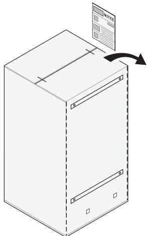
Package with installation template
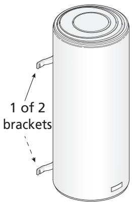
Your water heater: (for example: vertical wall-mounted)
| 50 liters | unavailable |
| 75 to100 liters | 1 |
| 150 to 200 liters | 2 |
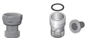
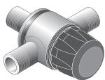
Dielectric union
Steatite models sheathed models
1.2. Accessories required
1.2.1. Mandatory and recommended accessories
To install your water heater, you need the following components:
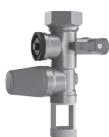
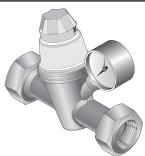
A NEW safety unit
Mandatory
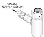
Siphon
Mandatory
Temperature limiter
Mandatory new and heavy repairs
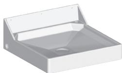
Water retention tank
Essential in the case of an installation on the floor and above a living space.

Wall outlet cable
Sealing tape or other


Pressure reducer
Mandatory if the water pressure in your house is greater than 5 bar (0.5 MPa). It must be installed at the meter outlet (see page 41)
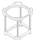
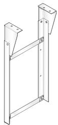
Tripod
For vertical wall-mounted models. Mandatory for walls not able to hold the weight for water heaters greater than 100L
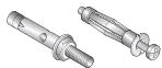
Mounting system
(0 10 mm min.)
Depending on support)
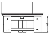
Surround kit for horizontal wall-mounted versions - Underside connection
Mandatory for mounting on the ceiling.
Can be used to replace the mountings of an older appliance. Enables the appliance to be slid a few centimetres during installation
1.2.2. Optional accessories
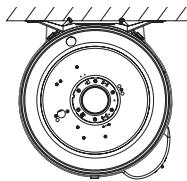
Ceiling attachment console
Ideal for mounting vertical wall-mounted water heaters to the ceiling, when the wall is not load bearing.
Frees up space under the water heater.
Quick mounting plates
Ideal for cramped places like a cupboard, where there is no access for tightening to the wall.
Reduced fitting time.
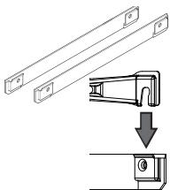
| Capacity | Number of plates |
| 50 to 100 litres | 1 |
| 150 to 200 litres | 2 |
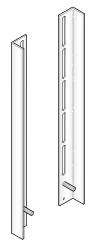
Universal mounting brackets
Ideal for re-using your old water heater's mountings with no additional holes
Reduced fitting time
Riser
Ideal for avoiding draining
modifications on vertical water heaters on a base
1.3. Tooling required
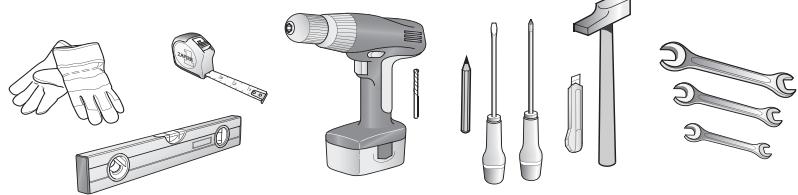
1.4. Labour

2 people required for assembly

2 hours
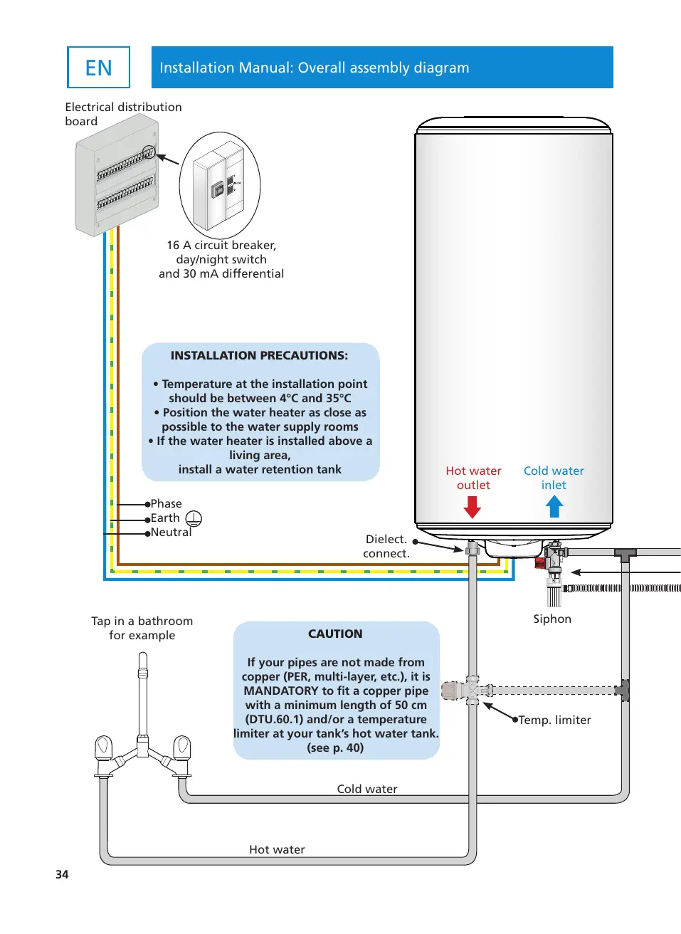
Electrical distribution board
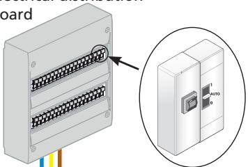
16 A circuit breaker, day/night switch and 30 mA differential
INSTALLATION PRECAUTIONS:
- Temperature at the installation point should be between 4^ and 35^
- Position the water heater as close as possible to the water supply rooms
- If the water heater is installed above a living area, install a water retention tank
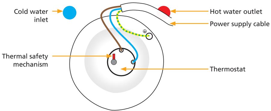
Hot water outlet
Cold water inlet


Dielect. connect.
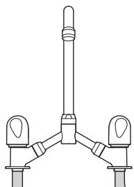
Tap in a bathroom for example
CAUTION
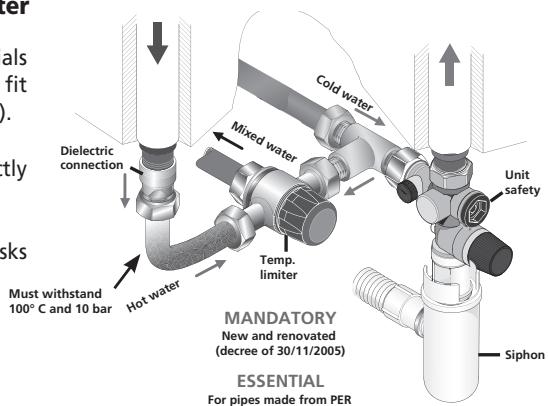
If your pipes are not made from copper (PER, multi-layer, etc.), it is MANDATORY to fit a copper pipe with a minimum length of 50 cm (DTU.60.1) and/or a temperature limiter at your tank's hot water tank. (see p. 40)
Cold water
Hot water
Siphon
Temp. limiter
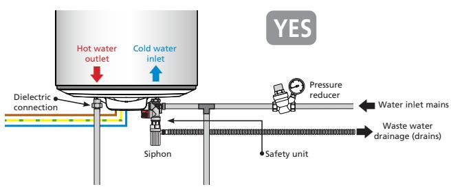
General installation diagram
Example with a vertical wall-mounted water heater
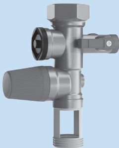
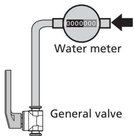
Pressure reducer
The pressure reducer is an additional accessory which should be installed at your water meter's outlet if the water pressure in your house is greater than 5 bar (0.5 MPa).
It prevents the safety unit's valve from opening erratically when the water heater is not operational.
To determine the water pressure in your house.
You can find out more from your water supplier
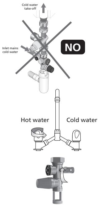
Warning: the pressure limiter must never be positioned between the safety unit and the cold water inlet

Pressure reducer
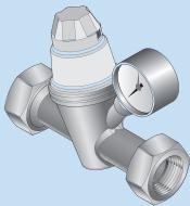
Safety unit
Safety unit
The safety unit is a mandatory accessory. Its role is to maintain an interior water pressure of 7 bar (0.7MPa) to prevent explosion (it fulfils the same role as a valve on a pressure cooker).
The safety unit therefore lets water escape when the water heater is operational. This flow may represent up to 3% of the volume of the water heater cycle.
Caution: the safety unit must always be directly connected to the tank's cold water tank. Nothing should be fitted between the safety unit and the water heater. (no valve, no pressure limiter, etc.).
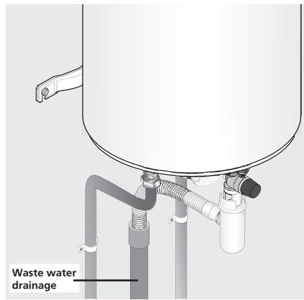
Mains water inlet
Waste water drainage (drains)
2. Where to install my water heater?
2.1 Precautions
- Choose a place of installation whose temperature is always between 4^ and 35^ .
- The water heater must be positioned as close as possible to the major draw-off points (bathroom, kitchen, etc.)
- If it is positioned outside the living area (cellar, garage), the pipes and the safety units (safety unit, pressure limiter) must be insulated.
- Make provision in the room for ventilation to prevent condensation and corrosion of the water heater paint.
- Ensure that the supporting element (wall or ceiling) is sufficiently resistant to accommodate the weight of the water heater full of water (see table p. 37).
- Make provision for a space of 40~cm for the periodic maintenance of the heater element.
- In the case of installation above living rooms (suspended ceilings, attics, etc.), it is ESSENTIAL to make provision for a water collection tank connected to the drain under the water heater (shower type tank for example).
2.2 Specific installation in the bathroom
- Installation outside these areas (NF C 15-100 or standards in force in the country).
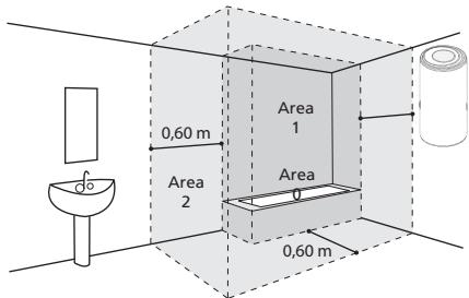
If bathroom dimensions do not allow the water heater to be positioned outside these areas :
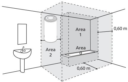
Possible in Area 2
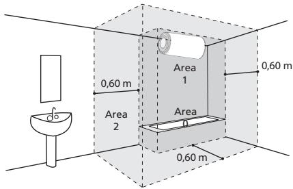
Possible in Area 1 if:
- the water heater is horizontal and positioned as high as possible
- the pipes are made from conductive material
- the water heater is protected by a circuit breaker residual differential current (30m A) connected
3. How to install my water heater?
3.1 Vertical wall-mounted water heater
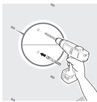
Cut the template printed on the cardboard and use it to make the markings
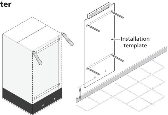
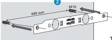
2 Drill then plug using (Ø) 10 mm mini mum diameter mountings suitable for your wall (plasterboard, concrete, brick).
Warning: your wall must be able to bear the weight of the full water heater.
If it cannot, use a tripod (see section dedicated to fitting on a tripod).
Approximate weight of full water heater
| Capacity | Weight |
| 50 L | 75 kg |
| 75 L | 100 kg |
| 100 L | 150 kg |
| 150 L | 200 kg |
| 200 L | 250 kg |
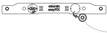
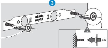
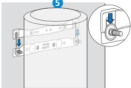
3 Once your water heater or easyFIX is in place, fix it on firmly
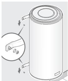
Without easyFIX
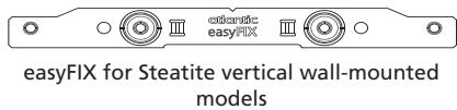
With easyFix for Steatite vertical wall-mounted models 75 L to 200 L.
1
3
5
2

4
Tightening torque : 29Nm max.
Specific case:
Fitting a vertical wall-mounted water heater on a tripod
The use of a tripod is mandatory when fitting a water tank with a capacity greater than 100L on a non load-bearing wall (cannot support the weight of the full tank).
First fit the water heater on its tripod in order to mark the mounting points.
Carry out the drilling.
Put the water heater back in place.
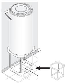

Mount the upper bracket.
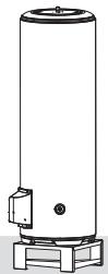
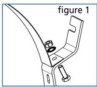
3.2 Vertical water heater on base
Fitting a vertical water heater on a base (fig. 1) does not require mounting.
Make sure you fit it on a flat surface.
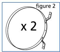
You can use a riser (fig. 2) to facilitate routing of the pipes.


1
2
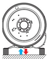
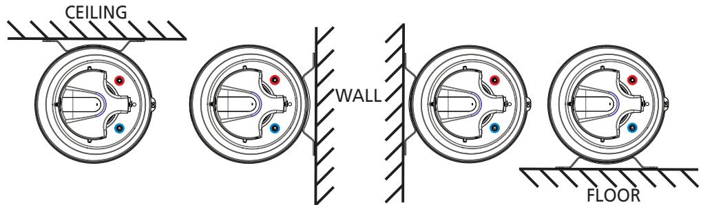
3.3 Horizontal wall-mounted water heater - Underside connection
A horizontal water heater can be fitted to the wall, ceiling or floor.

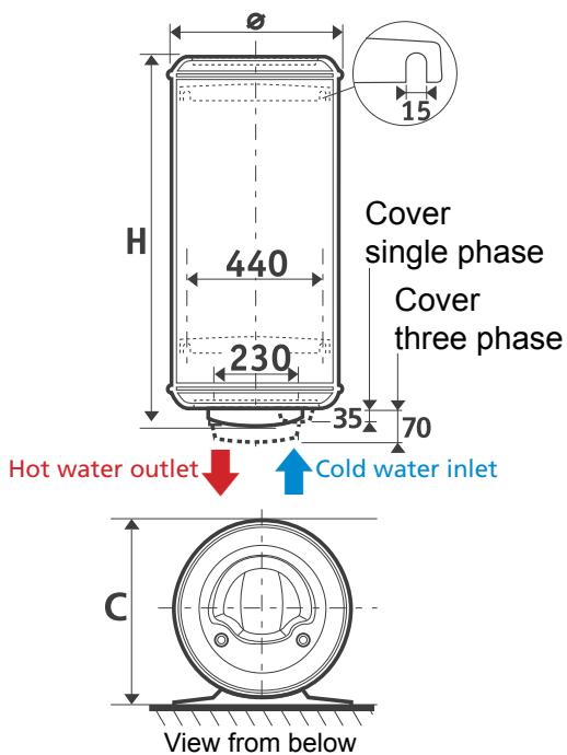
The cold water inlet and the hot water outlet must always be at the bottom.
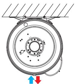
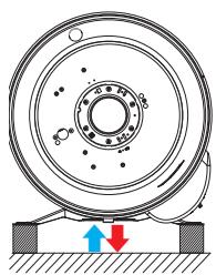
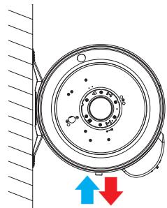
Leave a free space of 400mm underneath the cover in case the heater element in case the heater element needs to be replaced.
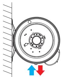
3.4 Horizontal wall-mounted water heater- Side connection

Essential:
Align the pick-ups vertically with the hot water outlet (red) above the cold water (blue).
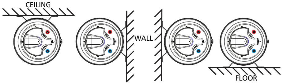
Mounting procedure:
- Assemble the belts and brackets using the nuts and bolts in the package without tightening them (figs. 1 and 2)
- Fit the brackets with their belt on the support (wall, ceiling, floor), then tighten
- Position the water heater using one of the 4 mounting options.
- Complete the mounting procedure by tightening the belt nuts on the bracket
4. Water heater water connections
The water heater must be connected in accordance with the standards and regulations in the country in which it is installed (for France: DTU Plumbing 60-1).
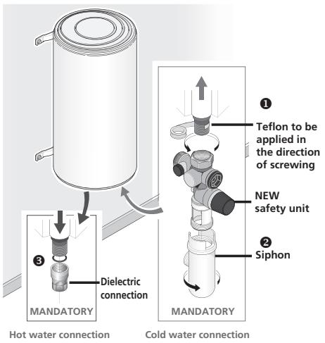
4.1 Conventional connection
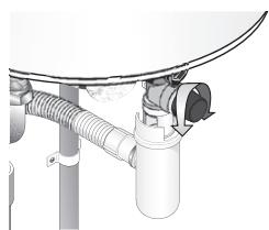
1 Connect the NEW safety unit to the cold water inlet (blue) on your water heater.
Place the siphon under the safety unit and connect its drain pipe to the drain.
3 Tighten the dielectric connection onto the hot water outlet (red) on your water heater.
4 Tighten your pipes on your water heater.

WARNING
Your pipes must be rigid (copper) or flexible (standardised braided stainless steel hoses) and able to withstand 100^ and 10 bar (1 MPa). Otherwise, use a temperature limiter.
4.2 Connection with a temperature limiter
If your pipes are made from synthetic materials (plastic or PER for example), it is essential to fit a temperature limiter (or thermostatic regulator).
The limiter must never be connected directly to the water heater.
The temperature limiter enables the risks of burning to be limited.
4.3 Connecting to a pressure reducer
The pressure reducer is mandatory if the water pressure in your home is greater than 5 bar (0.5 MPa).
Place it on the cold water inlet, to your water meter outlet, never directly to the water heater.
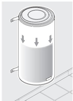
4.4 Filling the water heater
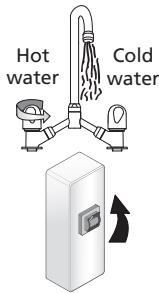
1 Turn on the house's HOT water taps.
Turn on the cold water valve located on the safety unit.
The water heater is filled as soon as you notice a flow of cold water at the hot water valve outlet.
Close these.
Check that the safety unit is operating correctly by moving the drain valve. A little water should flow out.
Check the sealing at the water inlet and outlets on the water heater.

Filling:
10 litres
a minute
If you notice a leak, try to retighten the connections.
If the leak persists, drain the water heater (see page 43) and retighten the connections.
Start the operation again until full sealing is achieved.
5. Connecting the water heater to the electricity


SWITCH OFF THE ELECTRICITY!
1 Check the compatibility of the water heater with the electrical installation.
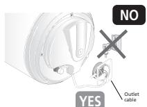
If the water heater is pre-wired, connect the water heater's power supply cable to a cable outlet (the water heater should not be connected to a socket).
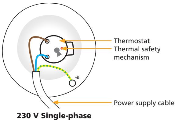
If the water heater is not pre-wired, the use of a rigid cable connection with a minimum cross-section of 3 × 2.5 ~mm^2 in single-phase (phase, neutral, earth) or 4 × 2.5 ~mm^2 in three-phase (3 phases + earth) is essential (refer to the «wiring diagram» section).
3 Check that the water heater is full by turning on a HOT water tap. COLD water should flow out. If the water heater is switched on when it is empty, there is a risk of damage (not covered by the warranty).
Switch the electricity back on.
A direct connection to the resistors (without passing through the thermostat) is strictly forbidden as it is extremely dangerous, the water temperature would not be limited.
6. Commissioning the water heater
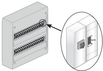
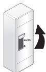
If your electrical distribution board is equipped with a day/night switch (reduced night tariff), move it to 1 (forced operation).
There may be some light smoke when heating starts (NORMAL operation).
After a while, water should flow drop by drop through the safety unit (connected to a waste water drain pipe). During heating, and depending on the water quality, the water heater can emit a sound similar to that made by a kettle. This sound is normal and does not mean there is a fault.
Wait for heating to finish before using your water heater fully (see specifications table to determine the estimated time depending on your model).


Heating time X = 8 hours
7. Domestic maintenance advice
Your appliance should be checked by a professional every 2 years, in order to guarantee its long-term performance.
7.1 The safety unit
Move the safety unit valve regularly (at least once a month).
This allows deposits which could block the safety unit to be drained away.
Failure to perform maintenance on the safety unit may result in deterioration of the water heater (not covered by the warranty).
7.2 Draining a water heater
If the water heater needs to remain switched off for more than a week (in a second residence for example), and it is located in a place exposed to frost, it is essential to drain the water tank in order to protect against corrosion.
Once the water heater is drained, bleed all the pipes in your house (turn on all your house's cold and hot water taps so that the pipes are empty).
Switch off the power

Turn off your general cold water inlet valve.
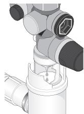
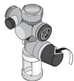
3 Turn the safety valve wheel (1 / 4 of a turn).
4 Turn on the HOT water valves in order to draw in the air.
The water heater is empty when the water stops flowing to the safety unit.
Draining can take up to one and a half hours or more.
Once completed, follow the steps in paragraph 6 "commissioning" (page 42) to return your water heater to working order.
7.3 Maintaining the tank
Check the condition of the magnesium anode every two years and replace it if its diameter is less than 10mm (in the case of ACI versions, the anode does not require any maintenance). It is strongly recommended to have maintenance performed on the tank by a professional every 2 - 3 years depending on the quality of the water: draining and limescale removal. In areas where the water is hard, it is possible to treat the water with a softener. This should be regulated and the water hardness should remain greater than 15^ .
Using a softener does not invalidate our warranty as long as it is used in accordance with professional standards, and is checked and maintained regularly.

Do not throw your appliance away in the domestic waste, but take it to a specially designated place (collection point) where it can be recycled.
8. Scope of the warranty
Failures caused by the following are not covered under this warranty:
8.1 Abnormal environmental conditions
- Damage caused by impacts or falls during handling after leaving the factory.
- Placing the appliance in a place exposed to frost or adverse weather conditions (damp, aggressive or poorly ventilated environments).
- Using a water with aggressivity criteria such as defined by the Plumbing DTU 60-1 addendum 4, hot water (chlorine content, sulphates, calcium, resistivity and TAC).
Water hardness < 15^ - Non-compliance with electrical mains standards (NF EN 50160) (power supply does not demonstrate min. or max. voltage, non-compliant frequencies, for example).
- Damage resulting from problems which cannot be detected due to the choice of position (difficult to access places) and which could have been avoided by immediate repair of the appliance.
8.2 An installation not compliant with the regulations, standards and good practice
- Missing or incorrect assembly of a safety unit compliant with standard EN 1487, or a change to its settings, etc.
- Fitting a hydraulic system directly onto the water system preventing operation of the safety unit (reduction in pressure, stop cock, etc.) (see page 41).
- Abnormal corrosion of pick-ups (hot or cold water) due to an incorrect water correction (incorrect sealing) or lack of dielectric sleeves (direct iron-copper contact).
- Faulty electrical connection: not compliant with standard NF C 15-100 or standards in force in the country, incorrect earthing, insufficient cable thickness, flexible cables connected, non-compliance with the connection diagrams provided by the manufacturer.
- Position of the appliance not compliant with the information in the instructions.
- External corrosion due to poor pipe sealing.
- Protective cover is missing or not correctly fitted.
- Cable sleeve is missing or incorrectly fitted.
- Appliance falls due to the use of mountings not suitable for supporting the installation.
8.3 Faulty maintenance
- Abnormal scaling of heater elements or safety units.
- Non-maintenance of the safety unit resulting in pressure surges.
- Modification of the original product without the manufacturer's advice or using spare parts not recommended by the manufacturer.
- Non-compliance with the magnesium anode maintenance conditions (see «tank maintenance» paragraph).
These devices comply with the directive 2014/30/UE according to electromagnetic compatibility, 2014/35/UE according to low voltage, 2011/65/UE according to ROHS directive and Commission Delegated Regulation 2013/814/UE supplementing 2009/125/EC regulation for ecodesign.
9. Warranty conditions
The water heater should be installed by a qualified professional in accordance with professional practice, the standards in force and our technical instructions.
It will be used normally and regularly maintained by a specialist.
In these conditions, our warranty covers the exchange or free supply to our Distributor or Installer of replacements to parts agreed to be defective by our staff, or if necessary of the appliance. It does not cover labour costs, transport costs, or any compensation or extension of the warranty.
The warranty takes effect on the date it is installed, the invoice for installation acting as proof. In the absence of documentary evidence, the date the warranty takes effect will be six months after the date of manufacture shown on the identification plate of the water heater.
The warranty on a part or a water heater replaced under warranty ceases at the same time as that of the part or water heater it replaced. (first part invoiced).
The provisions of these conditions of warranty do not exclude the benefits to the purchaser, or the legal warranty against faults and hidden defects which apply in all cases under the conditions of articles 1641 et seq. of the civil code.
In no case does the failure of a part justify the replacement of the water heater. Atlantic holds all the spare parts at your disposal for a period of 7 years.

An appliance which is presumed to have caused a fire must be left in place for examination by experts. The person affected should inform his insurance company.
Installation and Maintenance manual
Water heater
Contents
Technical Specifications
Technical specifications 47
Vertical wall-mounted water heater (VW) 47
Vertical water heater on base (VB) 49
Horizontal water heater (HM) connected underneath .... 50
Horizontal water heater (HM) side connection 51
Presentation of components 52
Shielded wall-mounted vertical versions 52
Steatite vertical wall-mounted models 52
Vertical models on shielded base 52
Steatite stable models 53
Shielded horizontal models 53
Specific installation procedures 53
Setting the temperature 53
Specific maintenance conditions 53
Parts which can be replaced 53
Troubleshooting guide 54
No hot water 54
Electric meter which breaks the circuit 55
Lukewarm water 55
Leak problem 56
Boiling noise 56
Water is too hot 56
I. Technical specifications
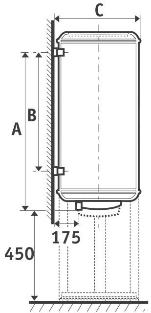
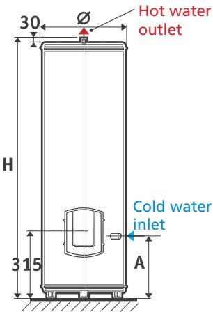
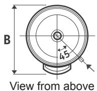
I.1 Vertical wall-mounted water heater (VW)
| 50 litres | 75 litres | 100 litres | |||||
| Voltage (V) | 230 V single-phase | ||||||
| Resistance | Shielded | Steatite | Shielded | Steatite | Shielded | Steatite | |
| Power (W) | 1,200 | 1,200 | 1,200 | 1,200 | 1,200 | 1,200 | |
| Dimensions (mm) | ∅ | 505 | 505 | 510 | 510 | 505 | 510 |
| H | 575 | 575 | 700 | 700 | 910 | 865 | |
| A | 370 | 370 | 575 | 575 | 750 | 750 | |
| B | / | / | / | / | / | - | |
| C | 530 | 530 | 530 | 530 | 530 | 530 | |
| Real heating time** | 2 h 26 min | 2 h 46 min | 4 h 10 min | 4h 10 min | 5 h 29 min | 5 h 46 min | |
| Qpr (Maintenance consumption)*** | 0.71 | 0.79 | 1.00 | 1.00 | 1.24 | 1.33 | |
| V40 (Amount of hot water at 40°C) | - | - | 141 | 141 | 179 | 192 | |
| Weight when empty (kg) | 23 | 23 | 26 | 26 | 32 | 30 | |
| Weight when full (kg) | 73 | 73 | 101 | 101 | 130 | 130 | |
| 150 litres | 200 litres | 200 litres | ||||
| Voltage (V) | 230 V single-phase | All currents* | ||||
| Resistance | Shielded | Steatite | Shielded | Steatite | Shielded | |
| Power (W) | 1,650 | 1,800 | 2,200 | 2,200 | 2,200 | |
| Dimensions (mm) | ∅ | 530 | 530 | 530 | 530 | 530 |
| H | 1,165 | 1,165 | 1,480 | 1,480 | 1,480 | |
| A | 1,050 | 1,050 | 1,050 | 1,050 | 1,050 | |
| B | 800 | 800 | 800 | 800 | 800 | |
| C | 550 | 550 | 550 | 550 | 550 | |
| Real heating time** | 5 h 33 min | 5 h 33 min | 5 h 17 min | 5 h 17 min | 5 h 17 min | |
| Qpr (Maintenance consumption)*** | 1.48 | 1.48 | 1.73 | 1,73 | 1.73 | |
| V40 (Amount of hot water at 40°C) | 279 | 279 | 382 | 382 | 382 | |
| Weight when empty (kg) | 38 | 38 | 46 | 46 | 46 | |
| Weight when full (kg) | 188 | 188 | 246 | 246 | 246 | |
| 100 litres compact | 150 litres compact | 200 litres compact | ||
| Voltage (V) | 230 V single-phase | |||
| Resistance | Shielded | |||
| Power (W) | 1,200 | 1,650 | 2,200 | |
| Dimensions (mm) | Ø | 570 | 570 | 570 |
| H | 735 | 1,000 | 1,250 | |
| A | 600 | 760 | 1,050 | |
| B | / | 500 | 800 | |
| C | 590 | 590 | 590 | |
| Real heating time** | 5 h 32 min | 5 h 38 min | 5 h 33 min | |
| Qpr (Maintenance consumption)*** | 1.024 | 1.37 | 1.67 | |
| V40 (Amount of hot water at 40°C) | 175 | 266 | 359 | |
| Weight when empty (kg) | 31 | 41 | 50 | |
| Weight when full (kg) | 131 | 191 | 250 | |
Real heating time for heating from 15^ to 65^ C
*Maintenance consumption in kWh for 24 hours for water at 65^ (ambiance 20^ )
Diagrammatic representation
1.2 Vertical water heater on base (VB)
| 150 l | 200 litres | 250 litres | 300 litres | |||||
| Voltage (V) | 230 V single-phase | |||||||
| Resistance | Shielded | Shielded | Steatite | Shielded | Steatite | Shielded | Steatite | |
| Power (W) | 1,650 | 2,200 | 2,200 | 3,000 | 3,000 | 3,000 | 3,000 | |
| Dimensions (mm) | Ø | 530 | 530 | 530 | 530 | 530 | 570 | 570 |
| H | 1,170 | 1,485 | 1,485 | 1,805 | 1,805 | 1,765 | 1,765 | |
| A | 300 | 300 | 300 | 300 | 300 | 300 | 300 | |
| B | 600 | 600 | 600 | 600 | 600 | 640 | 640 | |
| Real heating time** | 4 h 46 min | 4 h 41 min | 4h 57 min | 4 h 40 min | 4 h 55 min | 5 h 53 min | 5 h 37 min | |
| Qpr (Maintenance consumption)*** | 1.53 | 1.45 | 1.88 | 2.15 | 2.22 | 2.58 | 2.49 | |
| V40 (Amount of hot water at 40°C) | 259 | 358 | 354 | 477 | 465 | 569 | 531 | |
| Weight when empty (kg) | 37 | 43 | 43 | 57 | 58 | 65 | 68 | |
| Weight when full (kg) | 187 | 243 | 243 | 307 | 308 | 365 | 368 | |
| 200 l | 250 l | 300 l | ||
| Voltage (V) | All currents* | |||
| Resistance | Shielded | Shielded | Shielded | |
| Power (W) | 2,200 | 3,000 | 3,000 | |
| Dimensions (mm) | Ø | 530 | 530 | 570 |
| H | 1,485 | 1,805 | 1,765 | |
| A | 300 | 300 | 300 | |
| B | 600 | 600 | 640 | |
| Real heating time** | 4 h 41 min | 4 h 40 min | 5 h 53 min | |
| Qpr (Maintenance consumption)*** | 1.45 | 2.15 | 2.58 | |
| V40 (Amount of hot water at 40°C) | 358 | 477 | 569 | |
| Weight when empty (kg) | 44 | 57 | 68 | |
| Weight when full (kg) | 244 | 307 | 368 | |
Appliances supplied with three-phase wiring 230/400V3- can be switched to 230 V single-phase
Real heating time for heating from 15^ to 65^
**Maintenance consumption in kWh for 24 hours for water at 65^ (ambiance 20^ )
Diagrammatic representation
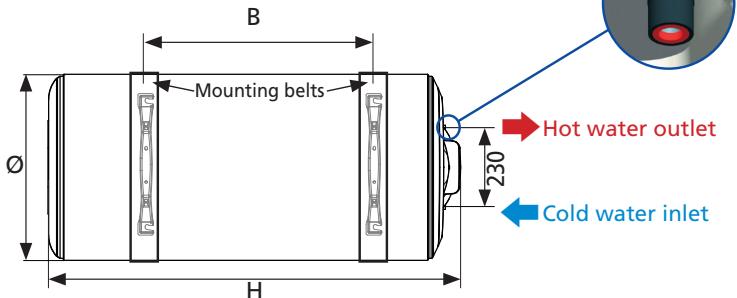
I.3 Horizontal water heater (HW) with underside connection
| 75 litres | 100 litres | 150 litres | 200 litres | ||
| Voltage (V) | 230 V single-phase | ||||
| Resistance | Shielded | ||||
| Power (W) | 1,200 | 1,200 | 1,650 | 2,200 | |
| Dimensions (mm) | Ø | 530 | 530 | 530 | 530 |
| H | 680 | 840 | 1,140 | 1,460 | |
| A | 370 | 500 | 800 | 800 | |
| B | 120 | 150 | 150 | 470 | |
| C | 145 | 275 | 575 | 575 | |
| Real heating time** | 4 h 07 min | 4 h 57 min | 4 h 53 min | 5 h 24 min | |
| Qpr (Maintenance consumption)*** | 1.29 | 1.34 | 1.75 | 1.98 | |
| V40 (Amount of hot water at 40°C) | 144 | 183 | 253 | 341 | |
| Weight when empty (kg) | 28 | 32 | 39 | 48 | |
| Weight when full (kg) | 103 | 132 | 189 | 248 | |
Real heating time for heating from 15^ to 65^ C
*Maintenance consumption in kWh for 24 hours for water at 65^ (ambiance 20^ )
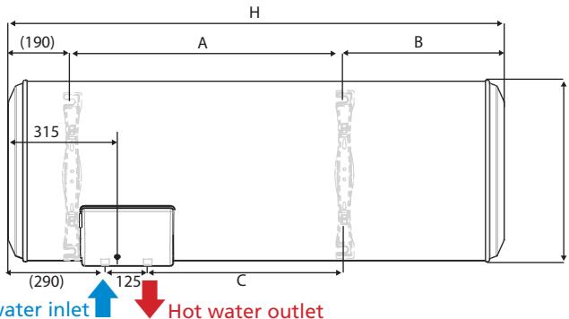
Diagrammatic representation
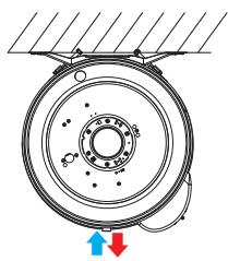
Various mounting options:

If mounting to the ceiling, it is essential to use the specifically designed surround kit 50(optional accessory, refer to its specific instructions).
I.4 Horizontal water heater (HW) side connection
| 75 litres | 100 litres | 150 litres | 200 litres | ||
| Voltage (V) | 230 V single-phase | ||||
| Resistance | Shielded | ||||
| Power (W) | 2,000 | 2,000 | 2,000 | 2,000 | |
| Dimensions (mm) | Ø | 505 | 570 | 570 | 570 |
| H | 740 | 745 | 1,000 | 1,255 | |
| B | Variable | ||||
| C | 530 | 590 | 590 | 590 | |
| Real heating time** | 2 h 36 min | 3 h 27 min | 4 h 41 min | 6 h 28 min | |
| Qpr (Maintenance consumption)*** | 1.34 | 1.54 | 1.89 | 2.15 | |
| V40 (Amount of hot water at 40°C) | 150 | 190 | 279 | 367 | |
| Weight when empty (kg) | 27 | 32 | 41 | 51 | |
| Weight when full (kg) | 102 | 132 | 191 | 251 | |
Real heating time for heating from 15^ to 65^ C
*Maintenance consumption in kWh for 24 hours for water at 65^ (ambiance 20^ )
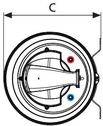
Various mounting options:

Align the take-offs vertically with the hot water outlet (red) above the cold water (blue).
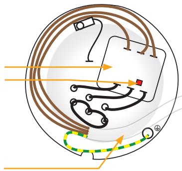
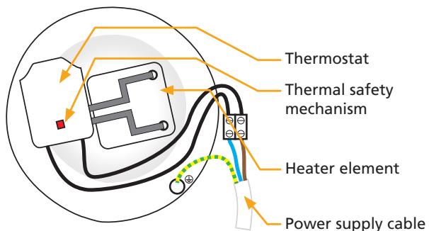
II. Presentation of the components
II.1 Components making up the shielded vertical wall-mounted models
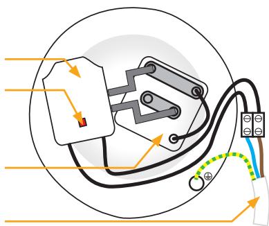
II.2 Components making up Steatite vertical wall-mounted models
II.3 Components making up vertical versions on shielded base
All currents
II.4 Steatite stable model components
200 L
250 and 300 L

II.5 Shielded horizontal model components
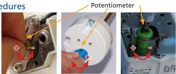
III. Specific installation procedures
Adjusting the temperature
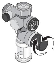
The factory temperature setting is 65^
The temperature may be lowered by turning the wheel.
IV. Specific maintenance conditions
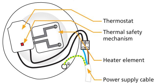
Parts that can be replaced
Thermostat
Cover
- Heater body (only for Steatite water heaters)
- Heater element
- Seal

The seal must be replaced if the heater body is replaced or opened.
Any replacement operation must be performed by a qualified person using the manufacturer's original parts.
V. Troubleshooting
V.1 No hot water
| Action to take | Solution | Cause |
| 1. Have the electrical power supply checked by a professional (using a multimeter). | If there is no current at the water heater's terminals: have an electrician look at it. | Electrical power supply fault. |
| 2. If you have Peak/Off-peak hours pricing, 2.1. Switch to forced operation from your electric distribution board. 2.2. Check the position of the circuit breaker (should be in the ON position) | If there is current at the water heater's terminals, go to the next step. | |
| 1. Cut-off the water heater current (the circuit breaker should be in the OFF position). | If the thermostat regularly goes into safety mode, descale the water heater (see the chapter on maintenance) and retighten all the electrical connections (after having switched off the power). | Thermostat going into safe mode. NOTE: it is preferable to replace the thermostat . if it goes into safe mode numerous times. (more than 10 times) |
| 2. Trigger the thermostat safety device again by pressing the red button (see section III). | ||
| 3. Switch to forced operation from your electrical distribution board. | If the safety device is not triggered, move onto the next step. | |
| 1. Cut-off the water heater power (the circuit breaker should be in the OFF position). | Null or infinite value. | Replace the faulty resistor. |
| 2. Take a resistance measurement at the heater element terminals using a multimeter (in ohm position). | Value in ohms > 0. | Replace the thermostat. |
V.2 Electric meter which breaks the circuit
| Action to take | Solution | Cause |
| 1. Check that the meter only cuts-out when the water heater starts heating. 2. If you have Peak/Off-peak hours pricing, 2.1 Switch to forced operation from your electrical distribution board. 2.2 Check the position of the circuit breaker (should be in the ON position). | The meter trips as soon as the water element circuit breaker is set to ON. On a shielded product: Replace the heater element. On a steatite product: Clean the area where the heater element is located (hollow interior) with a cloth or a bottle brush. If the problem persists: Replace the heater element. | Faulty resistor. Residue in the resistor sleeve. Faulty resistor. |
V.3 Lukewarm water
| Action to take | Solution | Cause |
| 1.1. Switch off the electrical power supply to the water heater. 1.2. Open the plastic cover. 1.3. Switch the thermostat to maximum. See Section III Setting the temperature. | Leave the thermostat setting at maximum in order to enjoy very warm water in sufficient quantity. | Incorrect thermostat setting. |
| 2.1. Shut off cold water inlet on the safety unit. 2.2. Turn on a hot water tap in the house. | If water flows from the hot water tap, then one of the house's taps is faulty. Replace the faulty tap or consult a plumber to find the cause of the problem. | A tap (mixer) allows cold water into the hot water circuit. |
V.4 Leak problem
| Action to take | Solution | Cause |
| Leak located on the hot and cold water take-offs | ||
| 1. Switch off the electrical power supply 2. Drain the water heater (see p. 43). | Reconnect all the connections (see p. 40, the section on installation). | Poor connector sealing |
| Leak coming from the nuts located under the plastic cover | ||
| 1. Switch off the electrical power supply 2. Drain the water heater (see p. 43). | Replace the closing flange seal | Damaged seal or leaking heater body. |
| Lek gezonden bij de bak | ||
| 1. Switch off the electrical power supply 2. Drain the water heater (see p. 43). | Replace the water heater. | Tank corrosion. |
V.5 Boiling noise
| Action to take | Solution | Cause |
| 1. Check that the noise occurs when the water heater is in the process of heating. | If the noise occurs during heating, descale the water heater (see Chapter 7.3 maintenance p.44). | Water heater is scaled up. |
| If the noise does not occur during heating or it consists of clicking noises, or it occurs when the valve is turned on, consult a plumber so that they can find the cause of the problem. | The water heater is not the cause. |

On a shielded product, this is a normal occurrence as the resistor is directly submerged in the water.
V.6 Water is too hot
| Action to take | Solution | Cause |
| 1.1. Switch the water heater's power supply off immediately. 1.2. Check the water heater's electrical wiring. | Reconnect the water heater's electrical wiring in accordance with the diagram on pages 52 and 53. | Connect directly to the resistor without passing through the thermostat. |
| 2.1 Turn off the water heater power supply. 2.2 Open the plastic cover. 2.3 Lower the temperature setting gradually using the wheel. See page 53, Section III Setting the temperature. | Adjust the thermostat to the desired temperature. | Thermostat set at the maximum. |
Procedure ter montage:
- 5 years for the tank for 50 to 500L water heaters and their heating elements sheath.
- 2 years for removable equipment : door seal, heating element, thermostat...
GARANTIEBON - TE BEWAREN DOOR DE GEBRUiker VAN HET APPARAAT - GARANTIE
- 5aar op de ketel voor boilers en hun verwarmingselementhuls.
-
2aarop demonteerbare onderleden:deurafdichting,verwarmingselement,thermostat…
-
Le remplacement d'un composant ou d'un produit ne peut en aucun cas prolonger la durée initiale de la garantie.
- Notre responsabilité ne saurait etre engagée pour des dommages causé par une mauvaise installation ou par le non-respect des instructions se trouvant dans le document. ATTENION : un produit présumé à l'origine d'un sinistre doit rester sur site à la déposition des experts d'assurance et le sinistre doit en informer son assureur. Tout remplacement doit se faire en accord avec l'assurance.
- Replacement of any component or product will in no case result in the extension of the initial guarantee period.
- Our responsibility can not be liable for damage caused by an improper installation or failure to follow instructions in this document.
WARNING: in the case of an insured event, the product has to be available to insurance adjusters and the victim has to informed his insurance provider. Insurance needs to agree with any replacement. - Da verwanging van een onderdeel zal in geen geval leiden tot verlenging van de oorspronkelijke garantieperiode.
Wijkonden noe gebed aansprakelijk worden gehouden voor schade die voortvloeit uen een verkeerde installmente of de Niet-naleving van de instructies in het document. OPGELET: indien een product word vtordersteld de oorsprong te zichen van de schade, moet这点 ter plaatie lijben ter beschikking van de experten van de verzekerung en he slachtoffer moist de schade melden aan zich verzekerung. Een verwangng kan enkel gebeuren met het akkoord van de verzekerung.
DATE D'ACHAT :
Model and serial n^ refer to the identification label of the water heater