PEMA965A - PEMA965C - Cooker DELONGHI - Free user manual and instructions
Find the device manual for free PEMA965A - PEMA965C DELONGHI in PDF.
User questions about PEMA965A - PEMA965C DELONGHI
0 question about this device. Answer the ones you know or ask your own.
Ask a new question about this device
Download the instructions for your Cooker in PDF format for free! Find your manual PEMA965A - PEMA965C - DELONGHI and take your electronic device back in hand. On this page are published all the documents necessary for the use of your device. PEMA965A - PEMA965C by DELONGHI.
USER MANUAL PEMA965A - PEMA965C DELONGHI
Instructions for use
Advice for installation
PYCCKN
KUXOHHЯ ПЛNTA C ДВΥМЯ ЗЛЕКТРИЧЕСКИМN ДУХОВКAMи IГА3ОВОΙ BAPOΥHΟΥ NOBEPEXHOCTьЮ
Hnctpykua nO 3KcnpyaTaauu
PekomeHdaun no yctaHOBKe
ENGLISH
- Instructions for use 3
- Advice for installation 30
PYCCKN
- INHcTpyKzIy IIO 3KcNpyatau. 43
·PeKOMeHdaUINno yCTaHOBKe 70
Dear Customer,
Thank you for having purchased and given your preference to our product.
The safety precautions and recommendations reported below are for your own safety and that of others. They will also provide a means by which to make full use of the features offered by your appliance.
Please preserve this booklet carefully. It may be useful in future, either to yourself or to others in the event that doubts should arise relating to its operation.
This appliance must be used only for the task it has explicitly been designed for, that is for cooking foodstuffs. Any other form of usage is to be considered as inappropriate and therefore dangerous.
The manufacturer declines all responsibility in the event of damage caused by improper, incorrect or illogical use of the appliance.
DECLARATION OF CE CONFORMITY
This cooker has been designed, constructed and marketed in compliance with:
- safety requirements of EEC Directive "Gas" 90/396;
- safety requirements of EEC Directive "Low voltage" 2006/95;
- protection requirements of EEC Directive "EMC" 89/336;
- requirements of EEC Directive 93/68.
IMPORTANT SAFEGUARDS AND RECOMMENDATIONS
After removing the appliance from its packing, make sure of its integrity. In case of doubt, please apply to your supplier or to a qualified engineer.
The packing materials (plastic bags, polyfoam, nails, metal strips etc.) must be moved away from the reach of the children as potential sources of danger.
- Do not attempt to alter the technical features of the appliance as this may result very dangerous.
- Do not carry out any operation of cleaning or maintenance without prior disconnection of the appliance from the electric supply.
- Do not line the oven walls with aluminium foil. Do not place baking trays or the drip tray on the base of the oven chamber.
- If you should decide not to use this appliance any longer (or decide to substitute an older model), before disposing of it, it is recommended that it be made inoperative in an appropriate manner in accordance to health and environmental protection regulations, ensuring in particular that all potentially hazardous parts be made harmless, especially in relation to children who could play with old appliances.
- Gas appliances produce heat and humidity in the environment in which they are installed.
Ensure that the cooking area is well ventilated by opening the natural ventilation grilles or by installing an extractor hood connected to an outlet duct.
- If the cooker is used for a prolonged time it may be necessary to provide further ventilation by opening a window or by increasing the suction power of the extractor hood (if fitted).
- Read the instructions carefully before installing and using the appliance.
CAUTION: this apparatus must only be installed in a permanently ventilated room in compliance with the applicable regulations.
IMPORTANT INSTRUCTIONS AND ADVICE FOR THE USE OF ELECTRICAL APPLIANCES
The use of any electrical appliance requires the compliance with some basic rules, namely:
- do not touch the appliance with wet or damp hands (or feet)
- do not use the appliance bare feet
- do not allow the appliance to be operated by children or disabled without overseeing.
The manufacturer cannot be deemed responsible for damages caused by wrong or incorrect use.
TIPS FOR THE USER
- During and after use of the cooker, certain parts will become very hot. Do not touch hot parts.
- Keep children away from the cooker when it is in use.
- After use, ensure that the knobs are in position (off), and close the main gas delivery valve or the gas cylinder valve.
In case of difficulty in the gas taps operation, call Service.
FIRST USE OF THE OVEN
It is advised to follow these instructions:
- Furnish the interior of the oven by placing the wire racks as described at chapter "CLEANING AND MAINTENANCE".
- Insert shelves and tray.
- Turn on the oven, and operate at the maximum temperature in order to eliminate any traces of grease on the heating elements.
- Clean the interior of the oven with cloth soaked in water and detergent (neutral) then dry carefully.
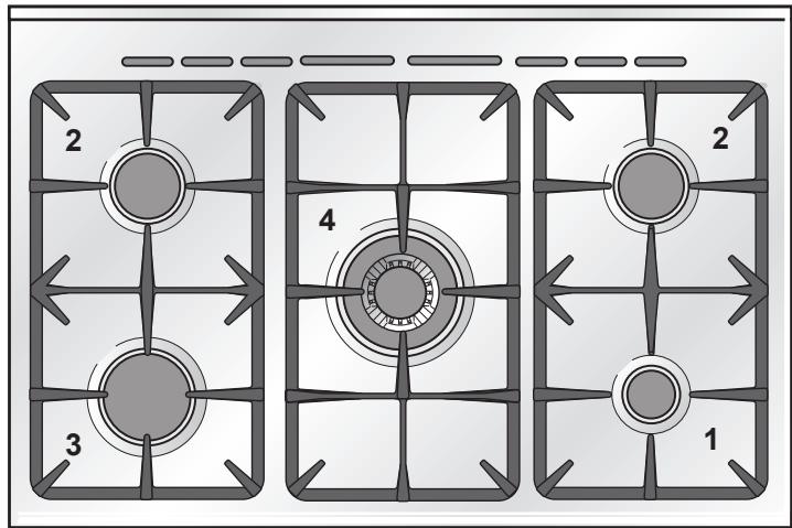
Fig. 1.1
COOKING HOB
- Auxiliary burner (A) 1,00 kW
- Semi-rapid burner (SR) 1,75 kW
- Rapid burner (UR) 3,00 kW
- Triple-ring burner (TC) 3,50 kW
Important Note:
The electric ignition is incorporated in the knobs.
- The appliance has a safety valve system fitted, the flow of gas will be stopped if and when the flame should accidentally go out.
The cooker has two electrical ovens:
- left multifunction main oven;
- right natural convection small oven.
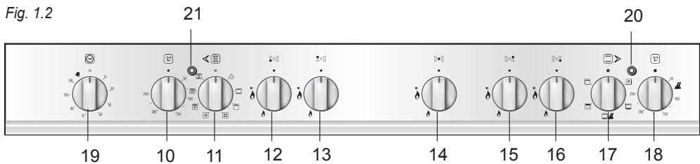
CONTROL PANEL - Controls description
- Multifunction main oven temperature knob (left oven)
- Multifunction main oven switch knob (left oven)
- Front left burner control knob
- Rear left burner control knob
- Central burner control knob
- Rear right burner control knob
- Front right burner control knob
- Conventional oven switch knob (right oven)
- Conventional oven thermostat knob (right oven)
- Timer 120' cut-off control knob (main oven only)
- Right oven thermostat indicator light
- Main oven temperature indicator light (left oven)
GAS BURNERS
Each burner is controlled by a gas tap which opens and closes the gas supply. Turning the knob so that the indicator line points to the symbols printed on the panel achieves the following functions:
-symbol = off
- symbol = full on (maximum rate)
symbol = minimum rate
The electric ignition is incorporated in the knobs ( symbol beside flame max. heat/max. gas flow (fig. 2.1).
The maximum setting permits rapid boiling of liquids, whereas the minimum setting allows slower warming of food or maintaining simmering conditions of liquids.
Other intermediate operating can be achieved by positioning the control knob indicator between the maximum and minimum setting, but not between the maximum and off positions.
N.B. When the cooker is not being used, set the gas knobs to their closed positions and also close the cock valve on the gas bottle or the main gas supply line.
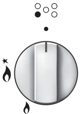
Fig. 2.1
LIGHTING GAS BURNERS Fitted With SAFETY VALVE DEVICE
To ignite the burner, the following instructions are to be followed:
1) Press in the corresponding knob and turn counter-clockwise (Fig. 2.2) to the full flame position marked by the 0 ) symbol (Fig. 2.1) and hold the knob in until the flame has been lit. In the case of a mains failure light the burner with a match or lighted taper.
2) Wait for about ten seconds after the gas burner has been lit before letting go of the knob (valve activation delay);
3) Adjust the gas valve to the desired position.
If the burner flame should go out for some reason, the safety valve will automatically stop the gas flow.
To re-light the burner, return the knob to the closed position, wait for at least 1 minute and then repeat the lighting procedure.
If your local gas supply makes it difficult to light the burner with the knob set to maximum, set the knob to minimum and repeat the operation.
In the case of a mains failure light the burner with a match or lighted taper.
Caution! The cooking hob becomes very hot during operation. Keep children well out of reach.
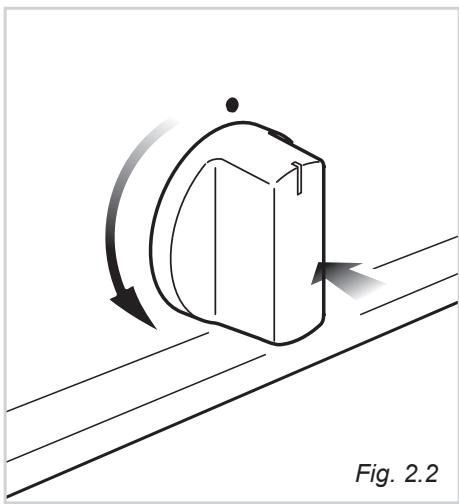
Fig. 2.2
CHOICE OF THE BURNER
On the control panel, near each knob, there is a diagram that indicates which burner is controlled by that knob.
Select the burner that is most suitable for the diameter and capacity of the pan to be used.
As an indication, the burners and the pans must be used in the following way:
| BURNERS | POT DIAMETER |
| Auxiliary (*) | 12 - 14 cm |
| Semi-rapid | 16 - 24 cm |
| Rapid | 24 - 26 cm |
| Triple-ring | 26 - 28 cm |
| do not use pans with concave or convex bases | |
(^*) with grill for small cookware:
minimum diameter 6 cm
It is important that the base diameter of the pot is at least the same diameter as the burner ring to obtain an efficient heat transfer.
Always position pans centrally over the burners.
Adjust the size of the flame so that it does not lick up the side of the pan.
Position pan handles so that they cannot be accidentally knocked.
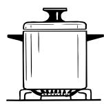
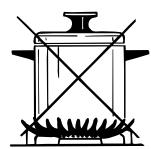
Fig. 2.3
GRATE FOR SMALL PANS
(fig. 2.4)
This grate is to be placed on top of the (smaller) auxiliary burner when using small diameter pans, in order to prevent them from tipping over.
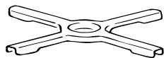
Fig. 2.4
Attention: the oven door becomes very hot during operation.
Keep children away.
GENERAL FEATURES
As its name indicates, this is an oven that presents particular features from an operational point of view.
In fact, it is possible to insert 7 different programs to satisfy every cooking need.
NOTE:
Upon first use, it is advisable to operate the oven for 60 minutes in the position with the thermostat knob set to 250^ and for another 15 minutes (thermostat knob on position 200) in the positions and to eliminate possible traces of grease on the heating elements.
Clean the oven and accessories with warm water and washing-up liquid.
WARNING:
The door is hot, use the handle.
During use the appliance becomes hot.
Care should be taken to avoid touching heating elements inside the oven.
IMPORTANT: to use the oven manually check that the control knob of the timer is in the position (see also the instructions at page 23).
Do not line the oven walls with aluminium foil. Do not place baking trays or the drip tray on the floor of the oven chamber.
MULTI-FUNCTION OVEN TECHNICAL FEATURES
The 7 positions, thermostatically controlled, are obtained by 4 heating elements which are:
- Lower element 1400 W
- Upper element 1000 W
- Grill element 2000 W
- Circular element 2500 W
OPERATING PRINCIPLES
Heating and cooking in the MULTIFUNCTION oven are obtained in the following ways:
a. by normal convection
The heat is produced by the upper and lower heating elements.
b. by forced convection
A fan sucks in the air contained in the oven muffle, which sends it through the circular heating element and then sends it back through the muffle. Before the hot air is sucked back again by the fan to repeat the described cycle, it envelops the food in the oven, provoking a complete and rapid cooking.
It is possible to cook several dishes simultaneously.
c. by semi-forced convection
The heat produced by the upper and lower heating elements is distributed throughout the oven by the fan.
d. by radiation
The heat is irradiated by the infra red grill element.
e. by radiation and ventilation
The irradiated heat from the infra red grill element is distributed throughout the oven by the fan.
f. by ventilation
The food is defrosted by using the fan only function without heat.
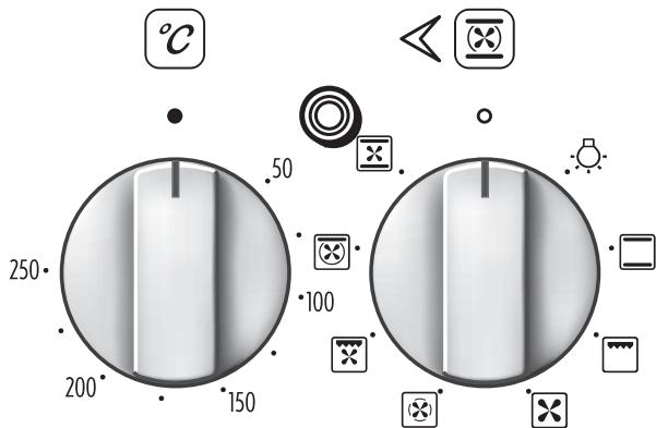
Fig. 3.1
Fig. 3.2
THERMOSTAT (Fig. 3.1)
To turn on the heating elements of the oven, set the switch knob on the desired program and the thermostat knob onto the desired temperature (from 50^ to 250^ ).
FUNCTION SELECTOR KNOB (fig. 3.2)
Rotate the knob clockwise to set the oven for one of the following functions:

OVEN LIGHT
By setting the knob to this position, only the oven light comes on (15 W). The light remains on whilst any of the cooking modes are selected.

TRADITIONAL CONVECTION COOKING
The upper and lower heating elements are switched on. The heat is diffused by natural convection and the temperature must be set between 50^ and 250^ . It is necessary to preheat the oven before adding the foods to be cooked.
Recommended for:
For foods which require the same cooking temperature both internally and externally, i.e. roasts, spare ribs, meringue, etc.
The infra-red heating element is switched on. The heat is diffused by radiation. Use with the oven door closed, the function knob set to l , and the temperature knob to position 225^ for max 15 minutes, then to position 175^ .
Note: It is recommended that you do not grill for longer than 30 minutes at any one time.
Attention: the oven door becomes very hot during operation. Keep children away.
For correct use see "USE OF THE GRILL"
Recommended for:
Intense grilling action for cooking with a broiler; browning, crisping, "au gratin", toasting, etc.

DEFROSTING FROZEN FOODS
Only the oven fan is on. To be used with the temperature knob on "●" because the other positions will have no effect. The defrosting is done by simple ventilation without heat.
Recommended for:
To rapidly defrost frozen foods; 1 kilogram requires about one hour.
The defrosting times vary according to the quantity and type of foods to be defrosted.

HOT AIR COOKING
The circular element and the fan are on. The heat is diffused by forced convection and the temperature must be set between 50^ and 250^ .
It is not necessary to preheat the oven.
Recommended for:
For foods that must be well done on the outside and tender or rare on the inside, i. e. lasagna, lamb, roast beef, whole fish, etc.
The infra-red ray grill and the fan are on. The heat is mainly diffused by radiation and the fan then distributes it throughout the oven. The temperature must be set between 50^ and 175 ^ C for max 30 minutes. It is necessary to preheat the oven for about 5 minutes.
Use with the oven door closed.
Attention: the oven door becomes very hot during operation.
Keep children away.
For correct use see "GRILLING AND "AU GRATIN".
Recommended for:
For grill cooking when a fast outside browning is necessary to keep the juices in, i. e. veal steak, steak, hamburger, etc.

THAWING AND WARMING UP
The upper element and the circular element connected in series, are switched on; also the fan is on. The heat is diffused by forced convection with the most heat being produced by the upper element.
The temperature must be set between 50^ and 140^ .
Recommended for:
To keep foods hot after cooking. To slowly heat already cooked foods.

CONVECTION COOKING WITH VENTILATION
The upper and lower heating elements and the fan turn on.
The heat coming from the top and bottom is diffused by forced convection.
The temperature must be set between 50^ and 250^ .
Recommended for:
For foods of large volume and quantity which require the same internal and external degree of cooking; for ie: rolled roasts, turkey, legs, cakes, etc.
COOKING ADVICE
STERILIZATION
Sterilization of foods to be conserved, in full and hermetically sealed jars, is done in the following way:
a. Set the switch to position
b. Set the thermostat knob to position 185^ C and preheat the oven.
c. Fill the dripping pan with hot water.
d. Set the jars onto the dripping pan making sure they do not touch each other and the door and set the thermostat knob to position 135^
When sterilization has begun, that is, when the contents of the jars start to bubble, turn off the oven and let cool.
REGENERATION
Set the switch to position and the thermostat knob to position 150^ C. Bread becomes fragrant again if wet with a few drops of water and put into the oven for about 10 minutes at the highest temperature.
ROASTING
To obtain classical roasting, it is necessary to remember:
- that it is advisable to maintain a temperature between 180 and 200^ .
- that the cooking time depends on the quantity and the type of foods.
SIMULTANEOUS COOKING OF DIFFERENT FOODS
The MULTI-FUNCTION oven set on position 空 and 空 gives simultaneous cooking of different foods.
Different foods such as fish, cake and meat can be cooked together without mixing the smells and flavours.
This is possible since the fats and vapors are oxidized while passing through the electrical element and therefore are not deposited onto the foods.
The only precautions to follow are:
-
The cooking temperatures of the different foods must be as close to as possible, with a maximum difference of 20^ - 25^ .
-
The introduction of the different dishes in the oven must be done at different times in relation to the cooking times of each one.
This type of cooking saves time and energy.
GRILLING AND "AU GRATIN"
Set the switch to position
Set the temperature knob to 175^ and after having preheated the oven, simply place the food on the shelf.
Close the door and let the oven operate until grilling is complete.
Adding a few dabs of butter before the end of the cooking time gives the golden "au gratin" effect.
Note: It is recommended that you do not grill for longer than 30 minutes at any one time.
ATTENTION: the oven door becomes very hot during operation.
Keep children away.
USE OF THE GRILL
Turn on the grill as indicated in the previous paragraph and leave to warm up for approximately 5 minutes with the door closed.
Introduce the food to be cooked, positioning the rack as close to the grill as possible.
The dripping pan should be placed under the rack to catch the cooking juices and fats.
Grilling with the oven door closed.
Grilling with the oven door closed and do not for longer than 30 minutes at any one time.
Attention: the oven door becomes very hot during operation.
Keep children away.
The oven accessories can bear loads up to 6kg
Distribute the loads uniformly.
OVEN COOKING
Before introducing the food, preheat the oven to the desired temperature.
For a correct preheating operation, it is advisable to remove the tray from the oven and introduce it together with the food, when the oven has reached the desired temperature.
Check the cooking time and turn off the oven 5 minutes before the theoretical time to recuperate the stored heat.
COOKING EXAMPLES
Temperatures and times are approximate as they vary depending on the quality and amount of food.
Remember to use ovenproof dishes and to adjust the oven temperature during cooking if necessary.
DISHES TEMPERATURE
Cakes 180°
Doughnuts 180^
Cheese souffle 200°
Potatoes souffle 200°
Roast veal 200^
Spinach crepes 200°
Potatoes in milk 200^
Chicken breasts in tomato 200°
Sole fish filet 200°
Whiting 200°
Cream puffs 200^
Plum pie 200°
Meat balls 200^
Veal meatloaf 200^
Grilled chicken - roast chicken 220^
Baked lasagna 220°
Roast beef 220^
Oven cooked pasta 220°
Lemon cake 220°
Rice creol 225°
Baked onions 225°
Stuffed potatoes 225°
Grilled veal joint 225°
Marmalade pie 225°
Pound cake 225°
Turkish shishkebab 250°
Pizza with anchovies 250°
Attention: the oven door becomes very hot during operation. Keep children away.
GENERAL FEATURES
The convection oven is equipped with 3 electrical heating elements:
- 2 elements (upper and lower) for normal oven cooking
- 1 grill element, on the top of the oven, for grilling.
The input of the elements is:
-Top element 700W
- Bottom element 800 W
- Grill element 1600 W
This oven is equipped with a special dish rack for use with the special function. In this setting you can use your conventional oven to warm the plates (at about 60^ ) before serving dinner.
For correct use of this function see "PLATE WARMING or TRADITIONAL CO NVECTION COOKING" and "USE OF SPECIAL DISH RACK".
NOTE:
Upon first use, it is advisable to operate the oven at the maximum temperature (thermostat knob on position 250) for 60 minutes in the position and for another 15 minutes in the position to eliminate possible traces of grease on the heating elements.
WARNING:
The door is hot, use the handle.
During use the appliance becomes hot. Care should be taken to avoid touching heating elements inside the oven.
Do not line the oven walls with aluminium foil. Do not place baking trays or the drip tray on the floor of the oven chamber.
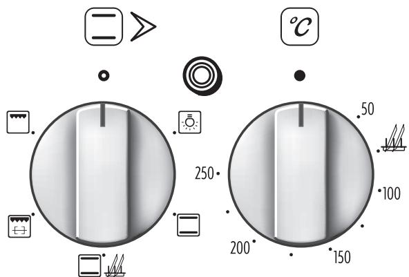
Fig. 4.1
Fig. 4.2
TEMPERATURE KNOB (Fig. 4.2)
This only sets the cooking temperature and does not switch the oven on.
Rotate clockwise until the required temperature is reached (from 50 to 250^ ).
FUNCTION SELECTOR KNOB (fig. 4.1)
Rotate the knob clockwise to set the oven for one of the following functions

OVEN LIGHT
By setting the knob to this position, only the oven light comes on (15 W). It remains on in all the cooking modes.

TRADITIONAL CONVECTION COOKING
This function can also be used for traditional convection cooking: the temperature knob must be regulated between 50 and 250^ . It is necessary to preheat the oven before introducing the foods to be cooked.
Traditional convection cooking recommended use:
For foods which require the same cooking temperature both internally and externally, i.e. roasts, spare ribs, meringue, etc.
The upper and lower heating elements are switched on; the heat is diffused by natural convection. The temperature knob must be set to position to heat the plates at about 65^ .
This function can also be used for traditional convection cooking: the temperature knob must be set between 50 and 250^ .
Recommended for:
Dish warming using the special rack. For correct use see "USE OF SPECIAL DISH RACK".
KEEP ATTENTION: Plates are hot after warming. It is advisable to handle the plates using oven gloves.

SPIT ROASTING
The infrared grill element at the top of the oven and the rotisserie motor comes on.
The heat is dispersed by radiation.
Use with the oven door closed, the function knob set to 网 , and the temperature knob to 225^ for max 15 minutes, then to 175^ .
For cooking hints, see "USE OF THE ROTISSERIE".
It is recommended that you do not grill for longer than 30 minutes at any one time.
Attention: the oven door becomes very hot during operation.
Keep children away.
Recommended for: Spit roasting with the rotisserie.

GRILLING
The infrared grill element at the top of the oven comes on. The heat is dispersed by radiation.
Use with the oven door closed, the function knob set to , and the temperature knob to position 225^ for max 15 minutes, then to position 175^ .
For cooking hints, see the chapter "USE OF THE GRILL".
Recommended use:
Intense grilling, browning, cooking au gratin and toasting etc.
It is recommended that you do not grill for longer than 30 minutes at any one time.
Attention: the oven door becomes very hot during operation.
Keep children away.
OVEN COOKING
Before introducing the food, preheat the oven to the desired temperature.
For a correct preheating operation, it is advisable to remove the tray from the oven and introduce it together with the food, when the oven has reached the desired temperature.
Check the cooking time and turn off the oven 5 minutes before the theoretical time to recuperate the stored heat.
COOKING EXAMPLES
Temperatures and times are approximate as they vary depending on the quality and amount of food.
Remember to use ovenproof dishes and to adjust the oven temperature during cooking if necessary.
| DISHES | TEMPERATURE |
| Lasagne | 190° |
| Baked pasta | 190° |
| Pizza | 220° |
| Creole rice | 190° |
| Baked onions | 190° |
| Spinach crêpes | 185° |
| Potatoes baked in milk | 185° |
| Stuffed tomatoes | 180° |
| Cheese soufflé | 170° |
| Roast veal | 180° |
| Grilled veal chops | 210° |
| Chicken breasts with tomato | 180° |
| Grilled chicken - roast chicken | 190° |
| Veal loaf | 175° |
| Roast beef | 170° |
| Fillet of sole | 175° |
| Aromatic hake | 170° |
| Beignets | 160° |
| Ring cake | 150° |
| Plum tart | 170° |
| Jam tartlets | 160° |
| Sponge cake | 170° |
| Sweet dough | 160° |
| Sweet puffs | 170° |
| Plain sponge cake | 170° |
USE OF THE GRILL
Preheat the oven for about 5 minutes.
Introduce the food to be cooked, positioning the rack as close to the grill as possible.
The drip tray should be placed under the rack to catch the cooking juices and fats.
Grill with the oven door closed.
Do not grill for longer than 30 minutes at any one time.
Caution: the oven door becomes very hot during operation. Keep children well out of reach.
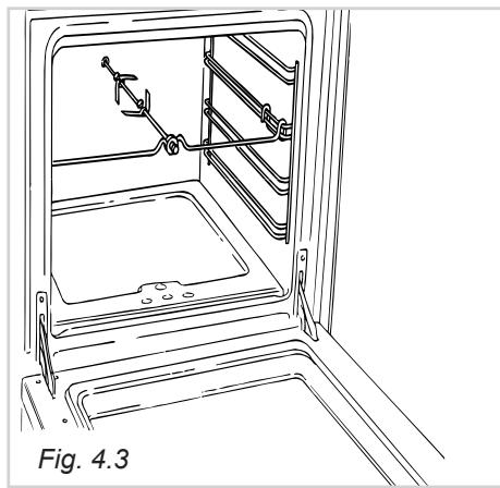
USE OF THE ROTISSERIE
(fig. 4.3)
- Insert the dripping pan into the lowest rack holders of the oven and insert the rod support into the intermediate rack holders.
Put the meat to be cooked onto the rod, being careful to secure it in the center with the special forks. - Insert the rod into the motor opening and rest it onto the support of the spit collar; then remove the grip by turning it to the left.
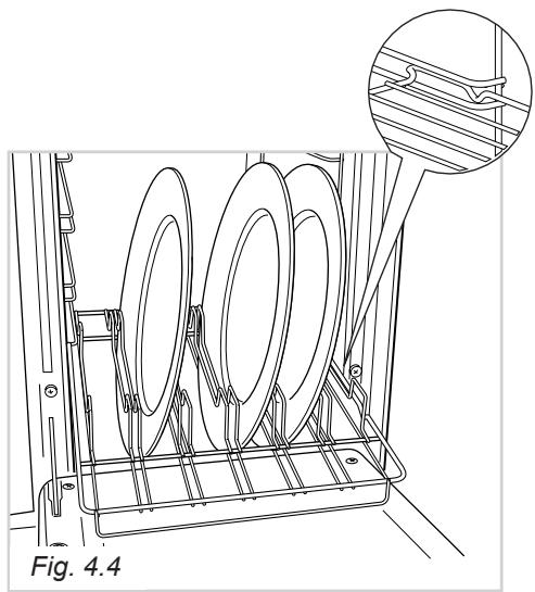
This special shelf can be used as a dish rack or when turned over, as a normal shelf for oven cooking.
It must be inserted between the guides of the lateral racks.
Slide in the shelf on the guides, on the lower level of the lateral racks.
The prongs where the plates are to be inserted must be turned upwards.
The shelf must be fitted so that the safety catch, which stops it sliding out, faces the bottom of the oven (see detail of figure 4.4).
The plates must be positioned as indicated in figure 4.4.
To facilitate this operation pull the special rack up to the safety lock.
KEEP ATTENTION: Plates are hot after warming. It is advisable to handle the plates using oven gloves.
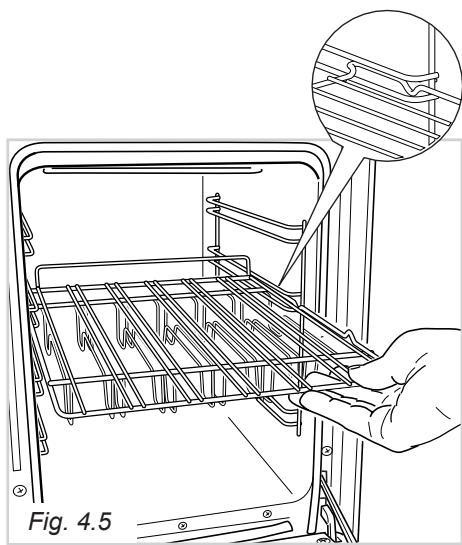
USING THE SPECIAL RACK FOR NORMAL COOKING
Slide in the shelf on the guides: the safety catch must be turned toward the oven base (see detail of figure 4.5).
The flat surface can be used to put cooking pans or to put food directly on the rack; in the second case the drip tray should be placed under the rack to catch the cooking juices and fats.
TIMER-120' Cut-off (Fig. 5.1)
The function of the timer runs the oven for a preset time.
1) Starting up.
After setting the function selector and thermostat to the required mode and temperature, rotate the timer knob clockwise until you reach the required cooking time (max 120 minutes).
Once this time has elapsed, the timer will return to the "0" position and the oven will automatically switch off.
2) Manual position.
If the cooking time is longer than two hours or if you wish to use the oven manually, switching it off as required, the knob must be turned to position
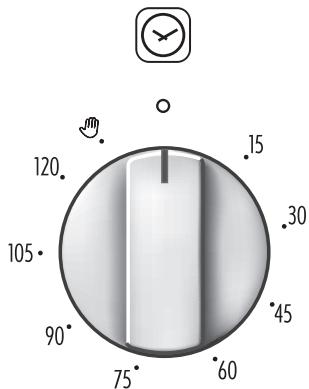
Fig. 5.1
GENERAL ADVICE
- Before any operation of cleaning and maintenance disconnect the appliance from the electrical network.
- When the appliance is not being used, it is advisable to keep the gas tap closed.
- Every now and then check to make sure that the flexible tube that connects the gas line or the gas cylinder to the appliance is in perfect condition and eventually substitute it if it shows signs of wearing or damage.
- Do not use cleaning products with a chlorine or acidic base.
- If a tap becomes stiff, do not force; contact your local Service Centre.
ENAMELLED PARTS
All the enamelled parts must be cleaned with a sponge and soapy water or other non-abrasive products.
Dry preferably with a soft cloth.
Acidic substances like lemon juice, tomato sauce, vinegar etc. can damage the enamel if left too long.
STAINLESS STEEL SURFACES
The stainless steel front panels on this cooker (facia, oven doors, drawer) are protected by a finger-print proof lacquer. To avoid damaging this lacquer, do not clean the stainless steel with abrasive cleaners or abrasive cloths or scouring pads.
ONLY SOAPY/WARM WATER MUST BE USED TO CLEAN THE (COATED) STAINLESS STEEL SURFACES.
REPLACING THE OVEN LIGHT BULB
Switch the cooker off at the mains. When the oven is cool, unscrew and replace the bulb with another one resistant to high temperatures (300^) voltage 230V 50 Hz),15W,E14.
Note: Oven bulb replacement is not covered by your guarantee.
GAS TAPS
In the event of operating faults in the gas taps, call the Service Department.
Do not use a steam cleaner because the moisture can get into the appliance thus make it unsafe.
INSIDE OF OVEN
This must be cleaned after every use. Remove and refit the side runner frames as described on the next chapter.
With the oven warm, wipe the inside walls with a cloth soaked in very hot soapy water or another suitable product. Side runner frames, tray and rack can be removed and washed.
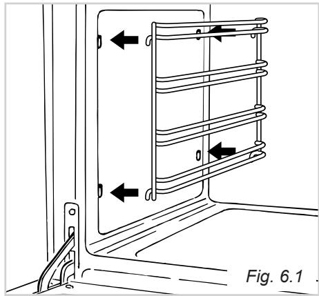
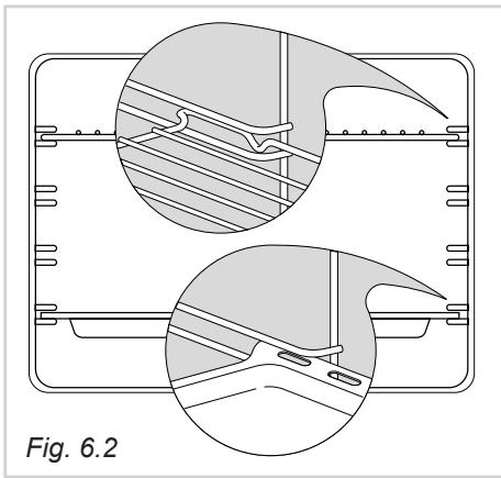
ASSEMBLY AND DISMANTLING OF THE SIDE RUNNER FRAMES
- Fit the side runner frames into the holes on the side walls inside the oven (Fig. 6.1).
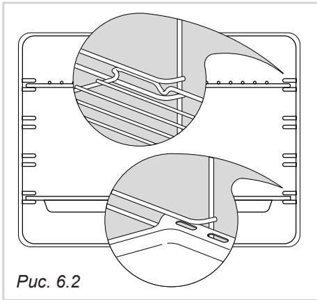
- Slide the tray and rack into the runners fig. 6.2. The shelf must be fitted so that the safety catch, which stops it sliding out, faces the inside of the oven.
- To dismantle, operate in reverse order.
BURNERS
They can be removed and washed with soapy water only.
They will remain always perfect if cleaned with products used for silverware.
After cleaning or wash, check that burner-caps and burner-heads are dry before placing them in the respective housings.
It is very important to check that the burner flame distributor and the cap has been correctly positioned - failure to do so can cause serious problems.
Note: To avoid damage to the electric ignition do not use it when the burners are not in place.
CORRECT REPLACEMENT OF THE BURNERS
It is very important to check that the burner flame distributor F and the cap C has been correctly positioned (see fig. 6.3 - 6.4) - failure to do so can cause serious problems.
Check that the electrode "S" (fig. 6.3) is always clean to ensure trouble-free sparking.
Check that the probe "T" (fig. 6.3) next to each burner is always clean to ensure correct operation of the safety valves. Both the probe and ignition plug must be very carefully cleaned.
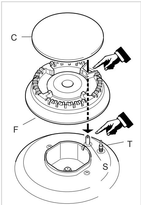
Fig. 6.3
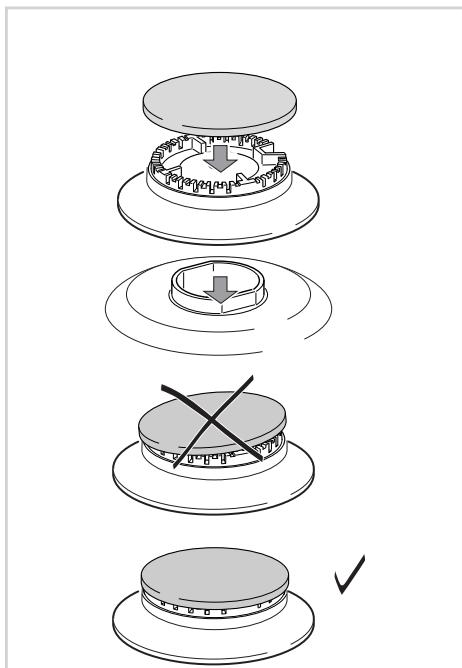
Fig. 6.4
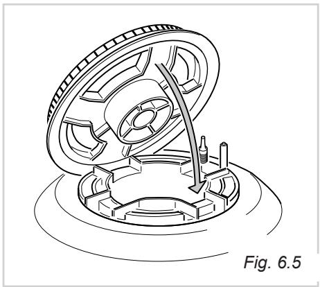
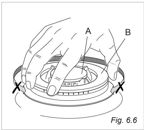
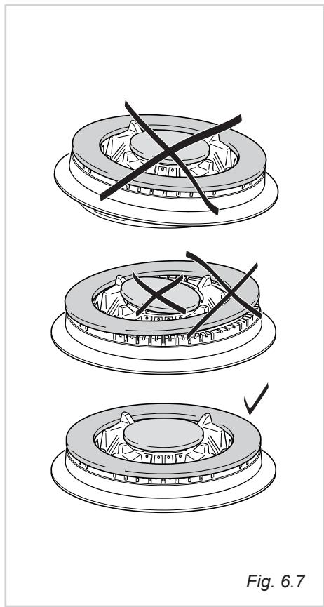
TRIPLE RING BURNER
The triple ring burner must be correctly positioned (see fig. 6.5); the burner rib must be enter in their logement as shown by the arrow.
Then position the cap A and the ring B (fig. 6.6 - 6.7). The burner correctly positioned must not rotate (fig. 6.6).
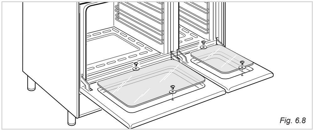
OVENDOOR
The internal glass panel can be easily removed for cleaning by unscrewing the 2 retaining screws (Fig. 6.8)
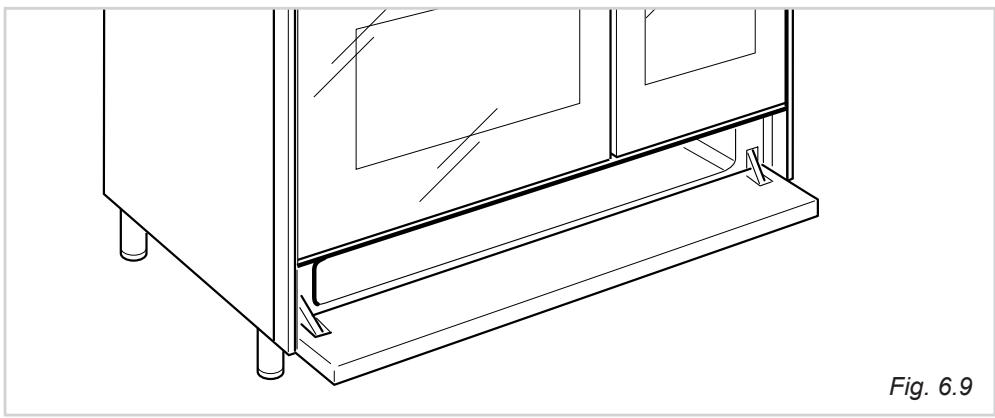
STORAGE COMPARTMENT
The storage compartment is accessible through the pivoting panel (fig. 6.9).
Do not store flammable material in the oven or in the storage compartment.
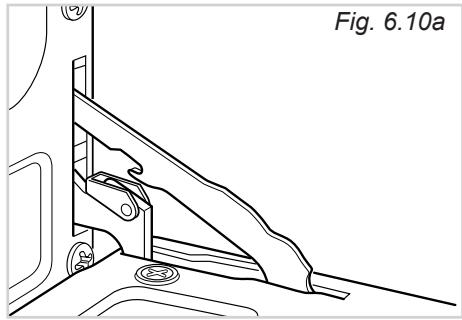
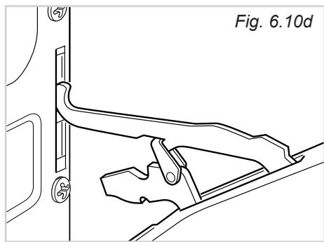
REMOVING THE OVEN DOOR
The oven door can easily be removed as follows:
- Open the door to the full extent (fig. 6.10a).
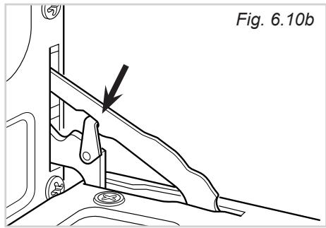
- Attach the retaining rings to the hooks on the left and right hinges (fig. 6.10b).
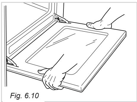
- Hold the door as shown in fig. 6.10.
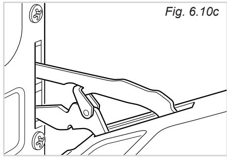
- Gently close the door and withdraw the lower hinge pins from their location (fig. 6.10c).
- Withdraw the upper hinge pins from their location (fig. 6.10d).
- Rest the door on a soft surface.
- To replace the door, repeat the above steps in reverse order.
Advice for the installer
IMPORTANT
- Cooker installation must only be carried out by QUALIFIED TECHNICIANS and in compliance with local safety standards. Failure to observe this rule will invalidate the warranty.
The appliance must be installed in compliance with regulations in force in your country and in observation of the manufacturer's instructions. - Always unplug the appliance before carrying out any maintenance operations or repairs.
- The surfaces of adjacent furniture and walls must be capable of withstanding temperatures in excess of 75^ . If the cooker is installed adjacent to furniture which is higher than the gas hob cooktop, a gap of at least 50mm must be left between the side of the cooker and the furniture.
- Some appliances are supplied with a protective film on steel and aluminium parts. This film must be removed before using the cooker.
The installation conditions, concerning protection against overheating of the surfaces adjacent to the cooker, must conform to figures 7.1a or 7.1b.
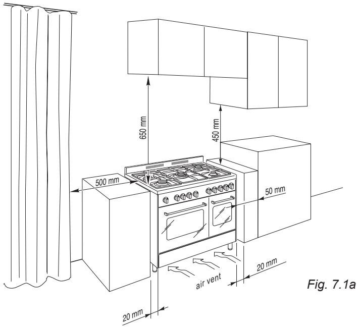
The walls of the units must be capable of resisting temperatures of 75^ above room temperature.
Class 1
Gas connection made using a rubber pipe which must be visible and available for inspection or using rigid or flexible metal pipe.
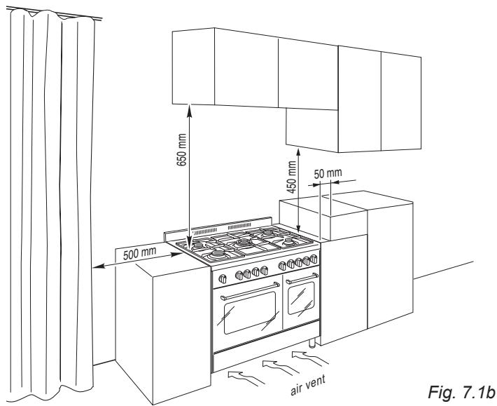
Fig. 7.1b
Class 2
Subclass 1
Gas connection made using a rigid or flexible metal pipe.
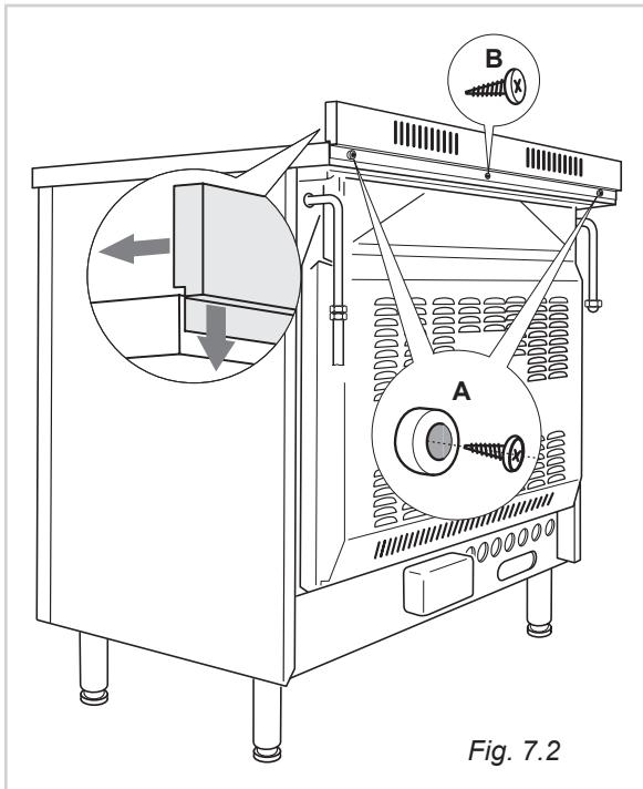
BACKGUARD
- Remove the two spacers “A” and the screw “B” from the rear of the cooker top.
- Assemble the guard as shown in figure 7.2 and fix it by screwing the central screw “B” and the spacers “A”.
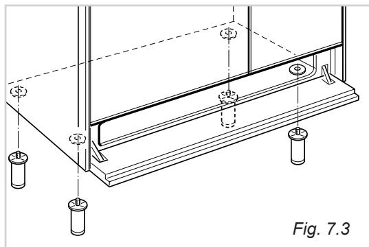
FITTING THE ADJUSTABLE FEET
The adjustable feet must be fitted to the base of the cooker before use.
Rest the rear of the cooker on a piece of the polystyrene packaging exposing the base for the fitting of the feet.
Fit the 4 legs by screwing them tight into the support base as shown in figures 7.3 - 7.4.
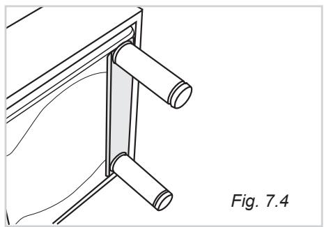
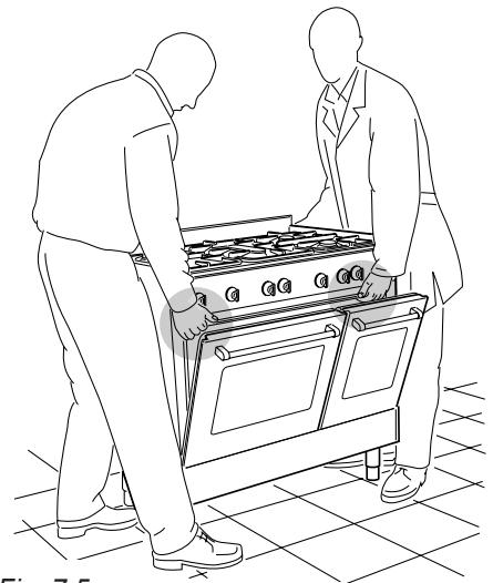
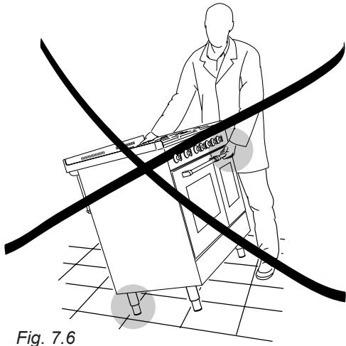
Fig. 7.5
Fig. 7.6
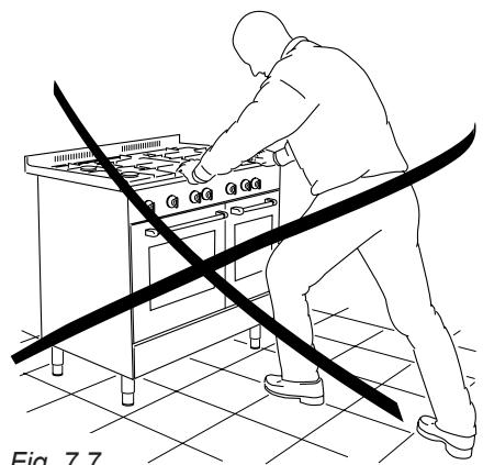
Fig. 7.7
MOVING THE COOKER
WARNING
When raising cooker to upright position always ensure two people carry out this manoeuvre to prevent damage to the adjustable feet and the sides (fig. 7.5).
WARNING
Be careful: DO NOT LIFT the cooker by the door handle when raising to the upright position (fig. 7.6).
WARNING
When moving cooker to its final position DO NOT DRAG (fig. 7.7).
Lift feet clear of floor (fig. 7.5).
The cooker may be levelled by screwing the lower ends of the feet IN or OUT (fig. 7.8).
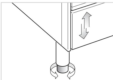
Fig. 7.8
In the room chosen to accommodate the gas appliance, there must be an adequate natural draft to allow combustion of the gas.
The natural draft must be produced directly by one or more vents made in the external walls and providing a total opening of at least 100~cm^2
The vents must be positioned close to the floor, preferably on the opposite side to the combustion discharge outlet and must be designed in such a way that they cannot be obstructed either from the inside or the outside.
When it is not possible to provide the necessary vents, the draft may be supplied from an adjacent room, ventilated in the required manner, provided it is not a bedroom or an area at risk.
In this event, the door of the kitchen must be opened to allow the draft to enter the room.
There must be a distance of at least 650~mm between the hob of the cooker and any wall cupboard or extractor hood positioned immediately above (see fig. 7.9).
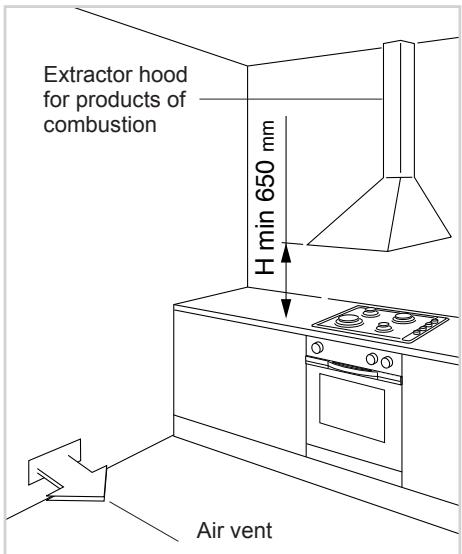
Fig. 7.9
Installation technicians must comply to current laws in force concerning ventilation and the evacuation of exhaust gases.
Intensive and prolonged use may require extra ventilation, e.g. opening a window, or more efficient ventilation increasing the mechanical suction power if this is fitted.
DISCHARGING PRODUCTS OF COMBUSTION
Extractor hoods connected directly to the outside must be provided, to allow the products of combustion of the gas appliance to be discharged (fig. 7.9).
If this is not possible, an electric fan may be used, attached to the external wall or the window; the fan should have a capacity to circulate air at an hourly rate of 3-5 times the total volume of the kitchen (fig. 7.10).
The fan can only be installed if the room has suitable vents to allow air to enter, as described under the heading "Choosing suitable surroundings".
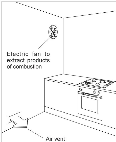
Fig. 7.10
The walls adjacent to the cooker must be of material resistant to heat.
GAS TYPES
The gases used for the operation of cooking appliances may be grouped by their characteristics into two types:
Cat: II 2H3+
-NATURAL GAS (G 20)
L.P.G. (in cylinders) (G 30/G 31)
Before installation, make sure that the local distribution conditions (type of gas and its pressure) and the adjustment of this appliance are compatible. The appliance adjustment conditions are given on the plate or the label.
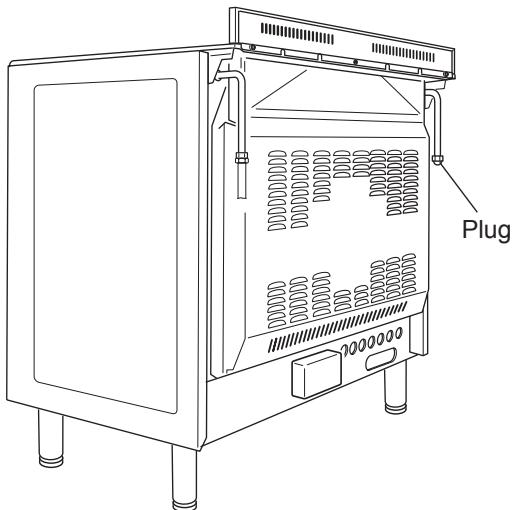
Fig. 8.1
GAS CONNECTION
The connection must be executed by a qualified technician according to the relevant standard:
The appliance is predisposed and calibrated to operate with the gas indicated on the specifications plate.
Make sure that the room where the cooker will be installed has adequate ventilation, in conformity with the rules in force, so that the appliance can work correctly; then connect the cooker to the cylinder or gas pipe respecting the rules in force.
The connection must be executed to the rear of appliance (left or right) (fig. 8.1); the pipe do not cross the cooker.
The unused end inlet pipe of the cooker (left or right) must be closed with the plug interposing the gasket.
If the appliance must be operated with a gas different than that indicated on the plate, it is necessary to execute the following operations:
- Gas connection.
- Replacement of the top injectors.
- Adjustment of the minimum of the top burners.
GAS CONNECTION WITH RIGID METAL PIPE OR HOSE
The cooker must be connected to the gas system using rigid metal pipes or continuous wall stainless steel hoses with threaded attachments, in conformity with standard with maximum length of 2000mm .
Be careful that metal hoses do not come into contact with movable or crushed parts.
The sealing gasket must conform to standards.
The connection with rigid metal pipes should not cause stresses to the gas inlet pipe.
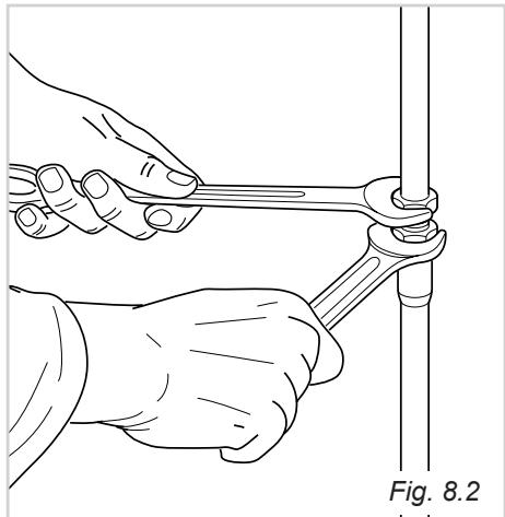
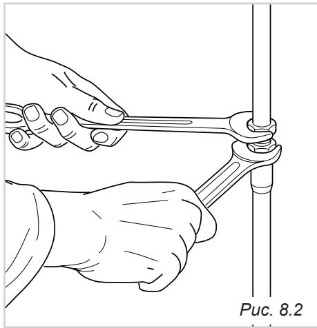
IMPORTANT:
Always operate with 2 spanners (fig. 8.2).
After connecting to the mains, check that the couplings are correctly sealed, using soapy solution, but never a naked flame.
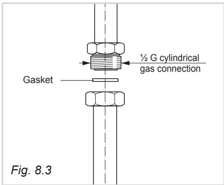
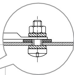
IMPORTANT:
The gasket "D" (fig. 8.3) is the element that guarantees the seal in the gas connection. It is recommended that it be replaced whenever it shows even the slightest deformation or imperfection.
In particular we recommend:
- That the connection with rigid metal pipes should not cause stresses to the gas inlet pipe.
- That the hose does not come into contact with hot parts of the cooker at any point.
- That the hose does not come into contact with cutting or sharp edges.
- That the pipe should not be subject to twisting and tensile stress and that it should not have curves which are too tight or be squashed.
- That the hose can be easily inspected along its length to check its state of wear.
- We advise replacing the hose at its expiry date or on any sign of deterioration.
- We advise replacing the gasket on the slightest sign of deformation or imperfection.
- That the cylinder or piping tap is closed immediately upstream of the appliance whenever it is not being used.
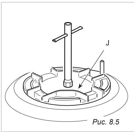
REPLACEMENT OF BURNER INJECTORS
If the injectors are not supplied they can be obtained from the "Service Centre".
Select the injectors to be replaced according to the "Table for the choice of the injectors".
The nozzle diameters, expressed in hundredths of a millimetre, are marked on the body of each injector.
To replace the injectors proceed as follows:
- Remove pan supports and burners from the cooktop.
- Using a wrench, substitute the nozzle injectors "J" (figs. 8.4, 8.5) with those most suitable for the kind of gas for which it is to be used.
The burners are conceived in such a way so as not to require the regulation of the primary air.
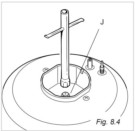
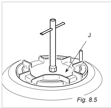
TABLE FOR THE CHOICE OF THE INJECTORS
| Air vent necessary for gas combustion = (2 m3/h x kW) | |
| BURNERS | Air vent necessary [m3/h] |
| Auxiliary (A) | 2 |
| Semirapid (SR) | 3,5 |
| Rapid (R) | 6,0 |
| Triple ring (TR) | 7,0 |
Cat: II 2H3+
| BURNERS | NOMINAL POWER [kW] | REDUCED POWER [kW] | G30/G31, 28-30/37 mbar | G20 20 mbar |
| Ø injector [1/100 mm] | Ø injector [1/100 mm] | |||
| Auxiliary (A) | 1,00 | 0,30 | 50 | 72 (X) |
| Semirapid (SR) | 1,75 | 0,45 | 65 | 97 (Z) |
| Rapid (R) | 3,00 | 0,75 | 85 | 115 (Y) |
| Triple ring (TR) | 3,50 | 1,50 | 95 | 135 (T) |
IMPORTANT
All intervention regarding installation maintenance of the appliance must be fulfilled with original factory parts.
The manufacturer declines any liability resulting from the non-compliance of this obligation.
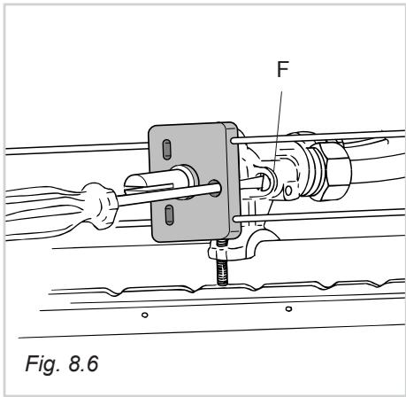
ADJUSTING OF THE MINIMUM OF THE TOP BURNERS
In passing from one type of gas to another, the gas flow must also be changed, considering that in this position the flame must have a length of about 4mm and must remain lit even with a brusque passage from the maximum position to that of minimum.
The flame adjustment is done in the following way:
- Turn on the burner
- Turn the tap to the MINIMUM position
Take off the knob
With a thin screwdriver pass by the hole of microswitch and turn the screw F until adjustment is correct (fig. 8.6).
Normally for G 30/G 31, tighten up the regulation screw.
LUBRICATION OF THE GAS TAPS
- In case of difficulty in the gas taps operation, call the After Sales Service.
IMPORTANT: The appliance must be installed in accordance with the manufacturer's instructions.
Incorrect installation, for which the manufacturer accepts no responsibility, may cause damage to persons, animals and things.
GENERAL
- Connection to the mains must be carried out by qualified personnel in accordance with current regulations.
- The appliance must be connected to the mains checking that the voltage corresponds to the value given in the rating plate and that the electrical cable sections can withstand the load specified on the plate.
- The appliance can be connected directly to the mains placing an omnipolar switch with minimum opening between the contacts of 3mm between the appliance and the mains.
- The power supply cable must not touch the hot parts and must be positioned so that it does not exceed 75^ at any point.
- Once the appliance has been installed, the switch must always be accessible.
N.B. For connection to the mains, do not use adapters, reducers or branching devices as they can cause overheating and burning.
If the installation requires alterations to the domestic electrical system, call an expert.
He should also check that the electrical system is suitable for the power absorbed by the appliance.
The connection of the appliance to earth is mandatory.
The manufacturer declines all responsibility for any inconvenience resulting from the inobservance of this condition.
Before effecting any intervention on the electrical parts of the appliance, the connection to the network must be interrupted.
ELECTRICAL FEEDER CABLE CONNECTION
To connect the supply cable:
- Remove the screws securing the cover "A" on the rear of the cooker (fig. 9.1).
- Feed the supply cable through the cable clamp "D". The supply cable must be of a suitable size for the current requirements of the appliance; see the section "Feeder cable section".
- Connect the wires to the terminal block "B" as shown in the diagram in figure 9.2; or connect the phase wires to the terminal block "B" and the earth wire to the terminal PE as shown in figure 9.1.
- Take up any slack in the cable and secure with the cable clamp "D".
- Replace the cover "A".
FEEDER CABLE SECTION Type HO5RR-F
230V
3 × 2,5 ~mm^2
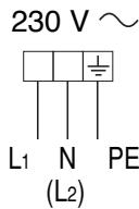
Fig. 9.2
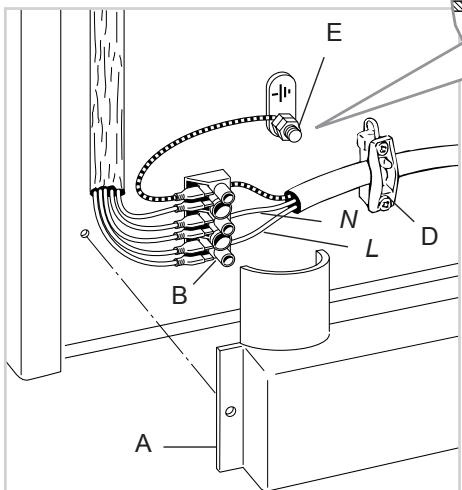
Fig. 9.1
Descriptions and illustrations in this booklet are given as simply indicative.
The manufacturer reserves the right, considering the characteristics of the models described here, at any time and without notice, to make eventual necessary modifications for their construction or for commercial needs.
Ybaxaembi nokynaTeNb!
Bnaeodapum Bac 3a mo, ymo Bby om-danu npednoymehue haweu npodykuuu.
LcIb npueedeHbix Hxue npaBn nOJIb-30BaHua u peKoMeHaauu - o6ecneueHue Bawe 6eOnacHocmu, a maKxe 6eOnacHocmu okpykaouux. Kpme mozo, c ux nomoubBo Bblcmoxeme MaksumalbHo UcnoJb3oamb BCEo3MoXHocmu ycmpoUcmeBa.
XpaHume daHnue u3daHue: OHO moJem noHaobumcBam unu okpykaouum 6byueme dner peuHnue oonpocoe, c8aHHbIX c yHKUohpuoaeHuE m obopydoeua.
Hacmoue ycmpoucmeo dojnxho 3kcnnyamupoeambc e nohom coomeemcmeuu co ceoum ha3nayehuem, mo ecmb dnn npuzomoehenu nuu. IcnoIb3o8aue obopdyo8aun e dpyux cyeJx cUmaemc HnnpaeBnHbIM u, cnedeoameJIbHO, onaChbIM.
Ipou3eodumelb chumaem c c68 ecio omeemcmbeHHocmb 3a noepexdeHua, e03Hukwue ecneocmeue he npabunbHO, ouu6oHou uu Hepa3ymHO 3Kcnpnyamauu ycmpoucmea.
3aBHeHne O nONHom COOTBeTCTBn Tpe6oBaHnM E3C
- Hactoiaa Ta bIJa cnpoeKtpoBaHa nckHouTEnbHO kAc yctpoiCTBO dI npiroToBneHnPiu. IcnoIb3ObaTHe ObOpyDoBaHnB Dpyrnx CEJx (OTOnJIeHnne NomeueHn) CHTaETcH HePpABInbHbIM n, CpeDObaTeNbHO, ONaChbIM.
-Плпаразработана,ИЗROTOВенаиЗалушега В пюдaxyв ПОЛHOM COOTBETCTBиC:
-Праиламп Тхнкь БсогаонсOTи,ИЗлж经HьIMВДирктпe «「a3» 90/396/CEE;
- Правиламп Т电商нki 6e3oNaChOCTn, ИЗLOжЕНыIMВ ДИректNBe «HиЗКоe HаряЖе» 2006/95/CEE;
- Tpe6oBaHnIyMn IO TeXHnke 6e3ONaChOCTn, yCTaHOBJIeHHbIMN B DInpeKtNBe
«ДиEkTpOMaHHTHaJ COBMeCTn~MOCTb» 89/336/CEE;
Tpe6oBaHnAIMm DInpeKtNbbl 93/68/CEE.

BAKHBIE INPABUNIA NOJb3OBAHnI PEKOMEHdaCNI
-Посл eи3BvneHn yCtpoiNCTBa n3 ynapOBKn y6eDnTecb B erO ueNoctHOCTn.В cnyaee Bo3NHOBHeH N KaKx-NI6o ComHeH N He nCnoJb3yIe TOBap n C8rXnTeCb C Baunm NoCTabUHKOM. XpaHnTe ynapOBoYnBle MaTePnAbl (nlaactNKOBbIe naKeTbI, noJIcTnTpoIbHbI neHOnPiAcT, rBO3dN, onOpHbIe DeTaN I T.I.). npEcdTabNIOUme noteHuaNbHyO onaChocT b dIra dTee, B HeDOCTyHOM dIra HNX MceTe.
-He nItaTeCb n3MeHnTb TexHnYeCKne XapaKTePnCTnKu n3JeNIA: 3TO ONaCHO.
- Onpaunno ouncke n texnueckomy oocnynbaHNO yctpoCTBa pa3peaaetc ocuecTBnIbKO NocJe OTKIOUeHnry yctpoCTBa OT nHTaOSeN 3JIeKTPnueeckOn CETN.
Bcnyae ecn Bblpeunte otka3atbcraotncnoj70BaHnna daHHoro yctpoiCTBa (NJIN peuHTe 3aMeHnTB CTapyO MOeIb Ha HOByO),MbI peKoMeHdyem Bam,nepeTtem KAK N36abNTcbr O TobopydOBaHnRA, BblIOI7HnTB P4N Mep, npedymOTpeHHbIX DeICTBYUOnMn HOpMaMn IIO oBeceNeHnIO 6e3oNaChocTN 3DopOBbY IN pEIDOTBpaueHnIO 3arp3HeHnO OkpyKaIoSe Cpebl nHaPpABLeHbIX HA npIBeHne HyeCTBA B Hepa76oOee coCToHnE. Kpome TOrO, Heo6xoDIMO 0e3Bpe7DITb 3JeMeHtBI ObopydOBaHnRA, KOToPBle MoryT cTaTB nCTOCHkAMn ONaCHOCTn DInrIrpaio7uX DeTeN.
- IcnoIb3ObaHne ra3OBoro yctpoiCTBa dIpy npiroTOBHeHn pyuBeTe K nobIeHIO TempeTpybI n BnaJxHOCTn B NOMEseHIn, B KOtOpOM yctaHOBIEHO daHoe o6OpyDobAHne. I03Tomy Heo6XoIMo N03a6OTNTbCRe O HApNExaSeE BHTINJIaCNI PnITbI: DepKNTe OTKpblIMN eCTeCTBeHHbIe BEHTINJIaONHbIe OTBepCTn INy UCTaHOBITE MEXaHueCECKOE BHTINJIaCIOHOHoe yctpoiCTBO (MexaHueCKeN BbITXHOK ONaK). B Cnyae INTHecNBHO INKcPlyataCNI YCTPOICTBA B TeUeHne DJInteBHLoro nepNoDA BPEMeHN MOJxET NOTpe6OBATcR DOONHITeNbHoe pOBeTpNaBHaHne, HAnpIMep, OTKpbITb OKHO, INI 6OJeE 3ΦΦekTNBHAR BeHTINJIaCn, HAnpIMep, YBeJIuHTb MOUTHOCb MEXaHueCKO BbITXKKN.
- YctaHOBka DaHHoro yCTpoiCtBA DoJnxHa OCyUeCTB'JYrTbC Ca C6OJIIOHeHMeI DeIcTByIOxH HOpM B Xo7pOio BeHTnIpyEOM NOMEuEHIN. IpeXJe Uem npIcTynITb K yCTaHOBKe IIN 3KcIpyataun DaHHoro yCTpoiCTBa, BHIMATEbHO IN3yUInTe INHcTpyKUn.
YcTpoIcTBO OCHaSeHIO OXlaJaIOUIM BEHTNJrTOpOM C aBTOMaTHueCKM 3aNyckOM.
BAKHBIE IPNABINIA NOJIb3OBAHnI IN PEKOMEHDAcNl
Bce 3neKtpnueckne yctpoicTba DoJKNbI NcPONb3OBaTbcra B COOTBeTCTBm C OCHOBbIMN IpabINJaAMN, B YacTHoCTn:
- DToTpaIbAToBcra Do yCtpoiCTBa MOKpbIMN IIN BnJXhblIMn pyKAMn IIn HOrAMn 3aPpeHcO;
- nCNoIb3OBaTb yCtpoIcTBo 6e3 06yBn 3anpeuHOr;
-Дунусякай Исторьане усторіства DeТьМи Лп НдесспосбъIMи ЛюдьМи 6e3 писмOTpa Дугин Лиц заразецно; - INCNoIb3OBAbT npooctpyHbIe npi6opbl 3aIpeuEHO, 3TO ONaCHO, NCKoIbKy Bnara MoKet npoHnKHyTB BHyTpB yCTpoIcTBA.
PEKOMEHDAUINIPO3KCIJYATAUIN
B npouecce 3Kcnnyataun HnneocpeDCTBeHNO nocne BbIKIOueHn TEmnpaTpya HeKOtOpbx Yacte nnIbI OueHb BbICoka. DToParNaBaTbcrdo Hnx 3anpeucho!
CneiTe 3a TEM, yTo6bI pAOM C PJIHTO H e 6blIO dTeH, ocObeHNO B npouecce ee 3KcnnyaTaun.
- Ⅰо 3аьершенин Испальзованя плNTы yбeДиТecь,чу yka3aTeNB pyKoRTК CTOnT B NOLOKeHenn 3AKPbITO, a takke nepekpoite ueHTpaNbHbI kpan noaun ra3a n3pacnpedeJInteHOBcETn nJIN Kpan Ha ra3OBOM 6aJINoHe.
- ПгИ ВОЗнКовенпpo6лeм C КраHamn Радун Ra3a ОрpaTHTecb 3a Тхнчecкоиnomo-цью.
OBUHEXAPAKTEPNUCTNKN
Kak BnIHO n3 onpeJeHnB Bam npednaeTcay duXOBka, 6bnaaIOUaO OoBeHHbIMN 3Kcnnyta- uOnHbIMn XapaKTePNCtUKAMN.
BbMOxKe BbIbpaT OINH 37 pa3nHybIX TINOB NOOrpeBaHn. TaKoB bI6Op No3BOJlEe TNOO6paT peXIM PnIroTOBJIeHn COrJaCHO INDINBUNaJIbHbIM Tpe6OBAHnM.
ПОНМЕЧАНЕ:
Ipe nepbom 3anycke B 3KcNlpyataunio Heo6xOДIMMO 3aKeYb NcyTyo DxyOBky cornaCHO yka3aHnM, KOtOpBie 6yDyT daHb 4yTb NO3dHee, IN DaTb eIN Ppa60TaTb npN MaKcImaJIbHOI TemnepaType, yCTaHOBnB pyKy TepMOCTATA B noJoxEne 250°C, npImepHo 1 cac B pexmme X I eue 15 MInHyB peKImax @ uX
3TO n03BOJNT yCTpaHnTB cNeIb CMa3Kn C 3NEKTPuuecknx pe3NCTOPOB.
BAXHOE 3AMEUAHNE:ДЯн HabtpoiKn DuxOBKn BpyHyu y6eIntecb, YTO pyka ynpaBHeHn TaImePOM yCTaHOBJIeHa B nOIOXeHne (cM. TaKx e YaKa-3aHHn Ha cTp.63).
Hn npK KaKnx ycJIOBnIe Hne NOKpbBaIte CTeHNyXOBKn aJIOMMHNEBOI FOJIb- ro. He cTabbTe IOTKN nIIN npOTNBn Ha OCHOBAHne DxyOBKn.
TEXHNUECKNE XAPAKTEPNUCTIKN MHYTOΦUHKUHOHAJIbHOJ DUXOBKN
- HnKnn HapeB 1400 Bt
-BepxHnHaRpeB 1000 Bt
-Γpnlb 2000Bt - Lürpkyiŋaɪy Bɔːdɪya 2500 Bt
PINHcIIbI PABOTbi
IpoDorpeBaHHe n pInroToBJeHne PmUe B MHOrofoHyHKuHOHaJIbHOJ dYxOBKe OcUeCTBnIOTc corlaCHO cNeDuOSei NHOpMaUIN:
a. MeToOM eCTeCTBeHHoH KOHBekun
TeIIO BbIpa6aTbIbAETcB EbpXHIM N HIXHIM HaPBeBaTeNbHbIM 3JEMeHTOM.
b. MeToDOM pInHyDnTeJbHoN KOHBeKcUH
BeHTnIaTOp 3a6bpaet Bo3dyx, HaxOJa-
IuC BHyTpN dyXOBKn, npOnyckaet erO
pee3 Cnpaun KpyroBOrO 3JKeTpUeCKo
rO JemEnTa I BO3BpaUaet B DYXOBky.
TporChn BO3dyx, IpexKJe cEm erO noBToP
HO 3acocet BeHTnIaTOp dJa npoxOXKeH
Hn BblSeONcaHHoro UcKNa, OKytlbAeT
PiDoyKTbI NITaHnB D yXOBKe, TEM CaMbIM
06ecneuBaB IN 6bICTpoE n paBHomepHoe
pnpiroTOBJIeHne.
c. MetoDom nonynpHnynteHbHO KONBekun
TeNIO, BbIpa6aTbIbAemoe BepXHIM N HIXHIM HaPeBaTeNbHbIMN 3IeMeHTAmn, paCnpEdeJIeTcBHyTpN dYxOBKn C NOMOuBbEOBHTNJTopa.
d. MeToDOM n3JyueHnA
TenIIO n3nyaetcNnDpaKpaChbIM 3JeMENTOM rPJI.
e. MeToDOM n3nyeHn I BeHTnIaIcN
TeIIO, n3JIyuaemoe INHppaKpaChbIM 3JEMeHTOM rPnIra, paCnpeJeIeTcB BHyTpN DxyOBKn C NOMOuB0 BEHTINrTOpa.
f. MeToDOM BeHTNJIAUIN
Пица разморжиBaetc cnomошьBOBHTNJIrTopa,6e3akTNBn3aunpexmaNoDOrpeBaHnA

Puc. 3.1
Puc. 3.2
PYUKA TEPMOCTATA (Pnc. 3.1)
Cnyknt NCKIIOHTeNbHO DnApeyIINPOBKn TEMNEPATpbl PnIROTOBNeHn IINu, HO He dN3aKInraHn dYXOBKn. POBepHnTe pyky no Yacoboi CTpeIke do Heo6xOIMOn TEMNEPAtpbl (B dnaIana30He ot 50 do 250^
PYUKA INEPKJIIOUATELEPAEXIMOB (Pnc. 3.2)
Bb6op c nOmoIbI nepeKJIIOUaTeIe pexIMOBn03BOINr Bam 3axkapuBaT npOdyKTb, HeNCNOb3y BepTeI, NCKoIbKy rOpAHI BO3dYpaBHomePHO oBOLaKnBaET npiroTaBnBaemblnpoDyKT.
YctaHObInTe pyKu TepMOCTaTa B noLoXeHne 175°C.3aTeM, npEdbapntEnbHo nporpeB dyXOBky, npOcTo noLOXnTe npOdyKT Ha peWeTky. 3akpoIte DBePuy N, Bblpab C nOMoubHo pyKu TepMOCTaTe TEMpePaTyP B dnaAzoHe OT 50 Do 175^ , OCTaBte DYxOBky Do 3aBepWeHnra Pnpoecca PnroTOBNeHnHa peWeTke. B KOHc De6BaBte HeckoJIbKO ToHKn X NOMtKOB CnBOOHOro MaNa, 3TO No3BOHnT NO3OJOTNb KopoOky, Obpa3OBAbUyIOcR B npOceCe 3aKapINBaHnN.
MaKcImaJIbHoe BpEma npriROToBHeHnHa rPnIe-30MmHyT.
BHHMaHHe: npn BbIbope pexmna npiroTOBNeHnHa rPnne HeKoTOpbIe DoCTynHbIe DeTAn MOryT HarpeBaTbcr. He noDnyckaIte DeTe K nIInTe.
NcNoJIb3OBAHNE TPNJIa
3ayncttepezim pnprotoblenha rpnelcornacno yka3aHnM,daHHbIM Bblie, npmepHO Ha 5 MNHyT, pni 3OM dBepca DoJxHa6b1b 3akpIta.
IocTaBbTe BHyTpB npOdyKTbI, KOTOpBIE ppeCToNT rTOBnTb, yCTaHOBB peWetKy KaK MoXHO 6nHex K rPnHIO.
Для сбopa сoka, obpa3ykuzeroCBA npoucece nprirotOBneHn, nopeWetKo nocTaBbTe npotuBeHb.
PnpiroTOBnHeHn HpInJe DOnJXHO npOTEkTb np3AkpyToN DBepeDyXOBKn.
MaKcMaJIbHoeBpeM npriROToBHeHnHa rpnIe-30 MNHyT.
BHHMaHHe: npn BbIbope pexmHa npiroTOBHeHn Ha rPIne HeKOTOpbIe DOCTynHbIe DeTAnMOryT HarpeBaTbcr. He noDnyckaTe DeTe K PJIInTe.
IeTani DuxOBKn MoryT BbIepeKaTb MaKcMmaHbHbB Bec do 6 Kr. PeKoMeHnyTeCpaBHomePHO paCnpEeJrTa Harpz3ky.
ПИГOTOBЛЕNHБ ВДУХОВКЕ
PpeKJe Yem CTaBnTb PPOyKtbl B DxyOBky, Heo6xOJIMO npEaBapnteJbHo pa30rpeTb ee do HyKnH Bam tempepatypbl.
Iocne toro, kak BHytpn DxyOBKn 6ydet DoCTHryTa XeNaemaTatemNepaTppa, CTabTe npOdyKtbl, 3aTe mnpOBepBte BpEM npriTOBHeHn, n BbIKHOnTe DxyOBKy 3a 5 MnHT do OKOHuaHn TeOpTeUcckoro BpeMeHn nprTOBHeHn, dIro toro UToBb6HDo CMOrNo 3a6paTb hakONJIeHHoe TEnIO.
ПРИМЕРы ПИГOTOBLEня
Hnke npBODaTc3NaueHnTeMnpaTpybI NCKIOUHTeNbHO DnI INHOpMaun, NCKOJIbKY B DeIeCTBNTeNbHOCTN TeMnpaTpa 3aBNCIT OT KaheCTBa I ObEma npOdykTa.
PekomeHdyetcnoJIb3ObaTbcSCKOBOpodAMN, NOxODaIuIMM IJIpyPiRTOBLeHnI NIIuIN B DxyOBKe,a TaKKe I3MeHnTb TeMpeatypy B DxyOBKe B IpOueCE PpiROTOBHeHn.
БЛЮДА TempepaTypa
Hnke npBODaTc3 3NaueHnA TeMnepaTypb B OC NCKJIOuHTeJIbHO dIy INHΦoPmaUIN, NOKOBKy B DeICTBNTeJIbHOCTN TeMnepaTypa 3aBNCIT OT KONUeCTBa.
BbITnpaTb DeTaN peKOMeHdyETcMaRKO TpA NOyKO.
BeueCTBa, coepkaune KncnoTy, Hanpimep COK NIMOHa, KOHceBupoBaHHbIX TOMaTOB, YKcyc nnn dpyrne noo6hbe npodykTbI, pni DInTeNbHom KOHTaKe T cMaIbIO pa3pyuHaOT ee, pnpabae en MaTOBb IOTeHOK.
IOBEPXHOCTN N3 HEPKABEIOUeI CTAJIN
BHIMAHNE
Ipeednne NOBepxHoctn n3 HepKabeOuSei CTaII (NaHeJIynpaBLeHnIA, DBePca DuyXOBKn IOTKpbIBaHOUeCEr OTcEKN), INCNoJIb3UOUeCEr B 3TOI PIIITe, NOKpblTbI CNEUaJIbHbIM 3aUHTNbIM CNOem PPO3paHOrO Jaka, PpeIaTCTByIOUeO NOBHeHIO OTNeuATKOB.
Дпя тоутобы He NOВpeintb 3aunTy 3TNX 3JIeMeHToB O6OpyIDOBaHn I3 HepKaeUoIeI CTaIи He NcPONb3yIte DЯ OChCTKn a6pa3nB-HbIe BeueceTb.
OuNCTKA NOBEPXHOCTEN3 HEPXABEOU CTAJIMoKET IPOUN3BOIDTBCOTJbKO C NOMOIO TOPAUEMbJIbHOBIObl.
CMA3KA ΓA3OBbIX KPAHOB
B cnyae ecnn KpaHbI cTaNyt nNoxo nobopa- uNbaTbcra, o6patntecb B ceHTp TexHnuecko noDepKKn.
NcnoJb30BaTb napoctpyHbIe np6oBpbl 3anpeuEHO, NOCKOJIbky BJara MoKet npOHKnHyTB BHyTpbyCTpoiCTBa, yTO npedctabJrET onaHocTb dIra pa6Otbl obOpdyOBaHn.
ДУХОВКА
Mоте духову посе кадого поцeccа рп�OTOBLEHЯ.
Дяг OЧИСТКИ BУТРЕн He NIOВЕХNOCTN DYXOB KOTCOEINHITe N BHOBc COБерпte 6OKOBbIe HAnpavBnOUIne COrNaCHO YK3AHNaM, DaHbIM HnIXe. Korda DyXOBKa cTahet npoxlaHON, NOMOIte CTeHKn TpRNoCHKo, CMOyeHHOH B OChEB TROPaYe MblbHoB BODe IIN DpyROM NOO6HOM pACTBope.
Bokobie HaprabJIOUne, npotnBeHb n peWetKy MoKHO BbITaUNTb N3 DyXOBKn I NOMbITb B MOKe.

MOHTAXNDEMOHTXEKOKOBbIX HAPRAPJIIOxN
BCTaBbTe 60KOBbIe HnPaBJIIOUcIe B OTBepCTINB 60KOBbIX CTeHKax DyXOBKn C BHyTpEHNe CTOpOHbI (Pnc.6.1).
BCTaBbTe B HnPaBnIooIyIO npOTnbEh bpeWetky, KaN pOKa3aHO Ha Pnc.6.2.PeWetkaYCTaHABnIBaETcTak, YTObI npEDoxpAHITelbHbI yNOP, IpeDToBpaAuaOuIIN clyuayHoe BbIaJeHne, 6bln NobepHyT BHyTpBdyXOBKn.
-ДемоHTax OCyUeCTBJIaTeTcB OobpaTHOM nopraKe.
TOPEJKN I PEWETKIN
MOxHO CHaTb N IOMblb TOJIbKO B MblbHOI BOe.
Cneinte 3a TeM, YTObI NOBepxHocTb Bcerda CBepkana, nepnoDnueckn HATnpa ee C nOMoUcpeCTBa, INCNoIb3yUOuXcxr dIpy ChCTKcepe6pa.
Iocne kaxdoon onepaunn ouncTk nIM MoKn y6eInTeCb, yTO paccKaTeIN PnaMeHn rOpelok n camn ropelkn cyxne n UcTaHOBJeHb I naJIeXaUIM o6pa30M.
HeoXoDIMO KOHTpOIpOBaTb NIOJoxHne pacCeKaTeIg PJIaMeHn, NOCKoJIbky erO CMeUeHne MoKcET CTaTb PNCHHOH HEnOJaOK.
PpmeaHne:Bo n36exaHne NOBpeXeHnHe NcNoIb3yIte yHKuNIO 3axnraHnE,ecnropeKn He yCTaHOBJIeHb B HxHHOeNOJKeHne.
IoiKluoyehne rata c coBIOJeHnEM BCEx MeCTbIX DeiCTByUOxH HOpM DoJIKeH OCyJcETBJIaTb TOnbKO KBaINΦuNpOBaHH BcEuaJIaNT.
ПлNTa cnpoeKtnpoBaHa n OtperynIpOBaHa c yuETOM pa6Otbl Ha r3e, Ha3BaHne n XapakTepeNCTNI KOTOPOro yka3aHbI Ha TabJInuChe, pa-nOLOKeHHo HA camOII NTte.
Y6eIntecb, YTO BeHTnJIaunB NOMeUeHnB, B KOTOPOM PnAhnpyeTc yCTaHOBKa DaHHoN pIITbI, OTBeuayet BcEM DeIcTByUOzIM HOpMam. 3aTeM NOCDcoEINHtE PnITy K Ra3OBomy BaIIHOHy nI IN Ra3ONpBOyB 3aBNCMOCTN OT TpeOBaHn, YCTaHOBNeHbIX B DeIcTByUOxIN HOpMax.
CoeunHeHne nIITbI c NCTOChNKOM ra3a ocUyIeCTBJIeTcC 3aJHeN CTOpONbI (Pnc.8.1) C NOMOuHIO npABORO IIN JEBORO BbIBOJa Ha nIInTe; Tpy6Ka He DoJnxHa NdTuYepe3 BCIO nIInTy.
HeicnoIb3yembl BbIOd Ha nnTe Heo6xoDIMO 3aKpbTb 3arnyuKOc yNtOHnTeNbHbIM KOJIbOOM.
Pn Heo6xOdMocTn NC0Nb3OBaHn Tnna ra3a,OTnUHOrO OT yKa3aHHOrO Ha Ta6nUKe, CJeDyET DeIeCTBOBaTb COJIaCHO yKa3aHnA M Hnke:
-ПодкнIoUeHneКИСТОУнkyra3a,
- 3aMeHa φopcyHok Ha pa6oey IOBepxHocTn,
-PerynnpobAHne MHNmyma Ipy ropeIOK ha pa6ooye nOBepxHocTn.
IPOJCOEINHEHNE K ICTOCHNYK Y RA3A C NOMOJIbIO TnBKOJ INJI XECTKOJ METAJJIHueCKOJ TPY6KN
ПлNTа coeINHЯETc r Ra3OBbIM OobopydObaHnEM C NOMOsbIO HeNpepbIBbIbIX JcEChKIN MTeaJIInueckHx TpybOK nI IN C NOMOsbIO rBbIKX TpyB6OK n3 HepxBaHeOSe cTaN C pe3b6ObbIMK KpePJIeHnMI CORNaCHO DeIcTByUoIIM HOpMaM, MaKcImaNbHoe pacuHne KOTopbIx COCTabJIeT 2000 MM.
O6paTnte BnHMaHne Ha TOT akT, YTO rB6KMe MeTaNlIueckne Tpy6Kn He DOnJXHbI KOHTaTKIpOBaTb C DBNraHouzIMNCr INI CdaBNeHHbIMN 3JIeMeHTaMn.
YJNIOHTHNTeJIbHOE KOJIbO DOJIxHO OTBeuATb Tpe6oBaHnM, yCTaHOBJIeHHbIM B COOTBetCTByIoueH HopMe.
OBPATITE BHIMAHNE:
Bce onepaunno npBnHnuBaHIO nn OTBnHnuBaHIO pe3nHOBOrdePkaTeN i cykaHoIero nepexoHNka DOnJXhI npOboNTbcra c nomoIu 2 Kluey (Pnc.8.2).
IIO 3aBepseHn NOkNIOUeHn IPOBepbTe repMeTNUHOCTb BCEx COeINHeHn C NOMOuMbIbHoro pactBopa. IcNoJIb3OBaHne ORHaJr 3TuX ueJe 3aPpeHo.
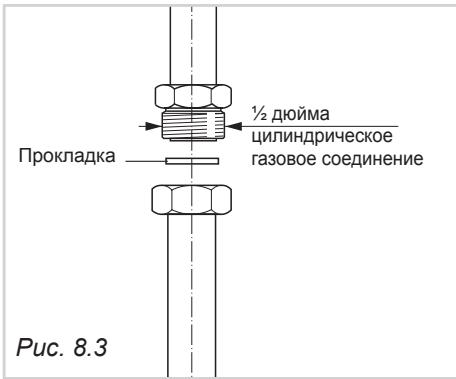
OBPATITE BHIMAHNE:
PpoklaKa «D» (Pnc.8.3) nCnoJb3yeTcAДЯ уллOTHeHnra3OBoRo coeDInHeHnPeKOMeHdYetc npOn3BODnTB 3aMeHy npOklaKn npn ObHApUxKeHm MaNeIuX npN3HaKOB DeOpMaun NIn NOBpeKdHnna.
B yacthoctn, pekomeHnyetcno obeceuHTb BbIOnHeHne CneDyUOxN Tpe6oBaHn:
- CoeHHeHne c nOMOuBHO JxctKnx MetaJIINueCKx Tpybok He DoJNkHo CO3daBaTb HaIpy3-Ky Ha BbIbO Ha NIIte.
-ΓιδΚαγ Μεταληνεκχα Κργόκα Ε ΦΟλχΗ ΚΟHTΑΝΟΒΑΤβς ΧρραύΠΜι ΣθεταλήΜι ΠπιNTbl.
Γκa Ma Tαλινηνεκαγ Tργδka He Κολχ- Ha KOHTaKπuPoBaTb C OCTpbIMn KpaMn NΠ KpaMn 3axBaTkn. - Tpy6ka He DoJnxHa Hn paTcIyBaTbc8, Hn nepeKpyuBaTbc8, B MeCTax I3r6a He DoJxHo 6blb Ype3MepHoro CkataN ynn nepeKIMOB.
-ДолжнабытбобспчehаBO3MOЖHOCTB6ecIpenЯTCTBENHOKHTPOJYCEIIOCTHOCTNtpy6knno BcEДПИHe. - PekomeHdyem npoI3BODnTb 3aMeHy Tpy6kn no nCTeHEnn ee cPoka 3KcPiIyatauIN nIN npn obHapUjKeHn mJeIuNX npn3HaKOB NOBpeXdEHH.
- PekomeHdyem npoun3bOuNb 3aMeHy ynpoTHeHn npn o6hApyKeHn MaNeIuNX npn3HaKOB deOpMaun nn NobpeXdHn.
Bcnyae HeNcNoJIb3OBAHnI pJIITbI peKoMeHdyETcI nepeKpbIbATb KpaH Ha 6aJIIOHe IINI paCnpdeJIteJIbHOI CETn, paCNOIarAOIuIICr BBePx NcENI OTHOCInTeJbHO IJIITbI.
3AMEHA ΦOPCYHOK FOPEJOK HA ΓA3OBOI PABOUEN IOBEPXHOCTN
Bce pntbI nocTbIaTcRc cepneI qpcSyHok, cnpoeKtnpoBaHbIX npd pa3nUHbIe Tnblra3a.
Ecnn B KOMnIeK T NOCTaBKn HE BkNIOUChEhbl yKa3aHHbIe DeTaN, INx MOxHNO pInOObpeCt N BuHTpax TexHnuecko NODepKKn.
Bb6op fOpcyHOK DOJIXeH OcUeCTBnTbCBA COOTBeTcBm C DaHHbIMN, PpNBEdeHHbIMN B Ta6NIue. DnaMeTp fOpcyHOK, BbipaxeHHbl B COTbIX MM, yKa3bIbAetcHa KOpnyce KaKdof fOpcyHKn.
3aMeHaΦoPcyHOK OcyIeCTBIIeTcB CJIeDyUo- UeM IopRdKe:
- CHMIMTe peWetky, KpbIWeuKN i pacceKaTeJN pIaMeHn ropeJOK.
C NOMOUbHJ XeCTKORO KJIHOa 3aMeHInTe CtaPbIeΦOpCyHKn Ha HOBbIe «J》(Pnc.8.4-8.5), cneuaIbHo CNpOeKtIPoBaHbIe IJa INcNoJIb3OBaHmHyXhORo Bam ra3a.
IopeJIku 6bIIpu pa3pa6omahbc yuemom ycmpaHnue Heo6xodumcu npoeedeHua pezunupoBaHnue nepuUHO2O 803dyxa.