DAP-2020 - Wireless Access Point D-LINK - Free user manual and instructions
Find the device manual for free DAP-2020 D-LINK in PDF.
User questions about DAP-2020 D-LINK
0 question about this device. Answer the ones you know or ask your own.
Ask a new question about this device
Download the instructions for your Wireless Access Point in PDF format for free! Find your manual DAP-2020 - D-LINK and take your electronic device back in hand. On this page are published all the documents necessary for the use of your device. DAP-2020 by D-LINK.
USER MANUAL DAP-2020 D-LINK
Wireless PoE Outdoor Access point
User Manual
Business Class Networking
Preface
D-Link reserves the right to revise this publication and to make changes in the content hereof without obligation to notify any person or organization of such revisions or changes.
Manual Revisions
| Revision | Date | Description |
| 1.00 | June 30, 2015 | • Initial release for revision A1 |
Trademarks
D-Link and the D-Link logo are trademarks or registered trademarks of D-Link Corporation or its subsidiaries in the United States or other countries. All other company or product names mentioned herein are trademarks or registered trademarks of their respective companies.
Copyright © 2015 by D-Link Corporation, Inc.
All rights reserved. This publication may not be reproduced, in whole or in part, without prior expressed written permission from D-Link Corporation, Inc.
Table of Contents
Preface
Package Contents. 1
System Requirements 2
Introduction 3
Features 4
Hardware Overview 5
Bottom Panel. 5
Physical Installation 6
Before You Begin 6
Safety Precautions 7
Physical Installation 8
Mounting the AP 10
Mounting the AP to a Pole 10
Mounting the AP to a Wall 11
Connect to your Network 12
Method 1 - Powered by PoE Switch 12
Method 2 - Powered by PoE Injector............13
Wireless Installation Considerations 14
Four Operational Modes 15
Configuration. 16
Web-based Configuration Utility 16
Save and Activate Settings. 17
Basic Settings 18
Wireless 18
Access Point mode 18
WDS with AP mode 20
WDS mode 22
Wireless Client mode 24
Authentication Types 26
Open System/Shared Key Authentication 26
WPA/WPA2-Personal Authentication. 27
WPA/WPA2-Enterprise Authentication 28
802.1x Authentication 29
LAN 30
IPv6 31
Advanced Settings 32
Performance 32
Wireless Resource Control 34
Multi-SSID 36
VLAN 37
VLAN List 37
Port List. 38
Add/Edit VLAN 39
PVID Setting 40
Intrusion 41
Schedule 42
Internal RADIUS Server 43
ARP Spoofing Prevention Settings 44
Bandwidth Optimization 45
AP Array 47
AP Array Scan 47
Configuration Settings. 48
Auto-RF 49
Load Balance 50
Captive Portal Authentication. 51
Web Redirect Only 51
Username/Password 52
Passcode 53
Remote RADIUS. 54
LDAP 55
POP3 57
Login Page Upload 58
IP Filter Settings. 59
MAC Bypass. 60
DHCP Server 61
Dynamic Pool Settings. 61
Static Pool Setting 62
Current IP Mapping List. 63
Filters. 64
Wireless MAC ACL 64
WLAN Partition 65
Traffic Control 66
Uplink/Downlink Settings 66
QoS. 67
Traffic Manager 68
Status 69
Device Information 69
Client Information 70
WDS Information 71
Channel Analyze 72
Statistics. 73
Ethernet 73
WLAN Traffic 74
Log 75
View Log. 75
Log Settings 76
Maintenance 78
Administration Settings 78
Limit Administrator 79
System Name Settings. 80
Login Settings 81
Console Settings 82
SNMP Settings 83
Status: 84
Ping Control. 84
Central WiFiManager Settings. 85
Firmware and SSL Certification Upload............86
Configuration File Upload 87
Time and Date 88
System 89
System Settings. 89
Help 90
Wireless Security 91
What is WEP? 92
Configure WEP 93
What is WPA? 94
Configure WPA/WPA2 Personal 95
Configure WPA/WPA2 Enterprise 96
Connect to a Wireless Network 97
Using Windows XP 97
Configure WPA-PSK. 98
Using Windows Vista 100
Configure WPA-PSK 102
Using Windows 7 103
Troubleshooting 106
Wireless Basics 110
What is Wireless? 111
Tips. 113
Wireless Modes. 114
Networking Basics 115
Check your IP address. 115
Statically Assign an IP address 116
Technical Specifications 117
Antenna Pattern 119
Central WiFiManager 138
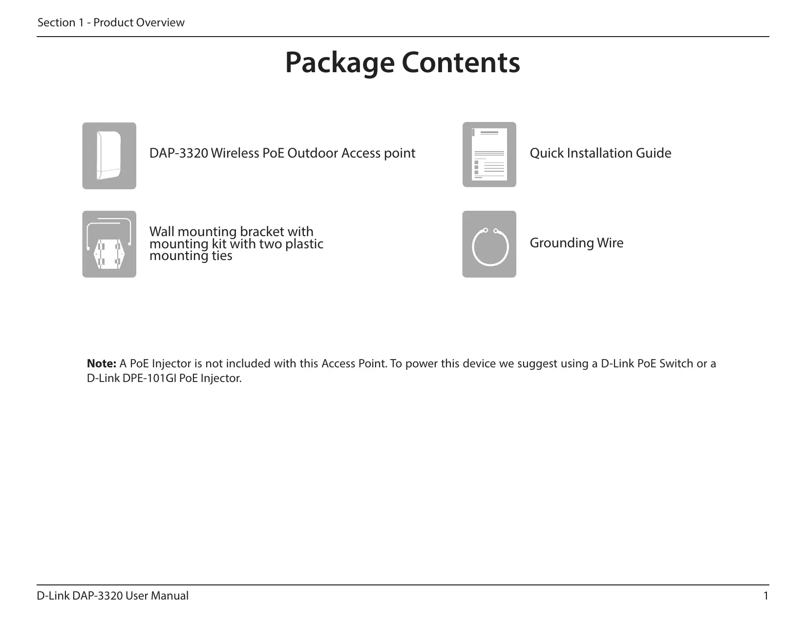
Package Contents
DAP-3320 Wireless PoE Outdoor Access point

Quick Installation Guide
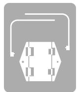
Wall mounting bracket with mounting kit with two plastic mounting ties

Grounding Wire
Note: A PoE Injector is not included with this Access Point. To power this device we suggest using a D-Link PoE Switch or a D-Link DPE-101GI PoE Injector.
System Requirements
| Network Requirements | ·An Ethernet-based Network ·IEEE 802.11n/g wireless clients (AP Mode) ·IEEE 802.11n/g wireless network (AP Mode) |
| Web-based Configuration Utility Requirements | Computer with the following: ·Windows®, Macintosh, or Linux-based operating system ·An installed Ethernet adapter Browser Requirements: ·Microsoft Internet Explorer® 8, Mozilla® Firefox® 28.0, Google® Chrome 33.0, or Safari® 5.1 or higher Windows® Users: Make sure you have the latest version of Java installed. Visit www.java.com to download the latest version. |
Introduction
The D-Link DAP-3320 Wireless PoE Outdoor Access point is an 802.11n compliant device that delivers real world performance of up to 300 Mbps* while still maintaining backwards compatibility with slower 802.11g and 802.11b devices. The DAP-3320 increases productivity by allowing you to work faster and more efficiently. With the DAP-3320, bandwidth-intensive applications like graphics or multimedia will benefit significantly because large files are now able to move across the network more quickly. Create a secure wireless network to share photos, files, music, video, printers, and network storage outside of your normal internal networking environment. Built to withstand harsh environments, the DAP-3320 also excels in connecting separate networks that cannot be joined physically using a traditional medium. The built-in omni-directional 2 dBi antenna is designed to deliver high powered performance, ensuring that wireless coverage will cover even hard to reach locations. The DAP-3320 is an ideal solution for quickly creating and extending a wireless local area network (WLAN) in offices or other workplaces, hotels, resorts, trade shows, and special events.
The DAP-3320 features four different operation modes: Access Point, Wireless Distribution System (WDS), WDS with AP, and Wireless Client mode, allowing it to adapt to many situations. As a standard wireless Access Point (AP) the DAP-3320 can connect to a wide range of devices that are 802.11 n/g/b compliant. In WDS mode it can expand current wireless coverage without the need for a wired backbone link. As a wireless client it can connect to an existing AP, and expand the network physically with the built-in 10/100 Ethernet port.
The DAP-3320 supports 64/128-bit WEP data encryption and WPA/WPA2 security functions. In addition, it provides MAC Address Filtering to control user access, and the Disable SSID Broadcast function to limit unauthorized access to the internal network. Network administrators have multiple options for managing the DAP-3320, including Web (HTTP) or Secured Web (HTTPS). For advanced network management, administrators can use SNMP v1, v2c, v3 to configure and manage access points.
*Maximum wireless signal rate derived from IEEE Standard 802.11n and 802.11g specifications. Actual data throughput may vary. Network conditions and environmental factors, including volume of network traffic, building materials and construction, and network overhead can lower actual data throughout rate.
Features
- Faster Wireless Networking - The DAP-3320 provides an up to 300 Mbps* wireless connection with other 802.11n wireless clients. This capability allows users to participate in real-time activities online, such as video streaming, online gaming, and real-time audio.
- Compatible with IEEE802.11g Devices - The DAP-3320 is still fully compatible with the 802.11g standards, so it can connect with existing 802.11g adapters.
- Four different operation modes - Capable of operating in one of four different operation modes to meet your wireless networking needs: Access Point, WDS with AP, WDS, and Wireless Client.
- Power over Ethernet - The DAP-3320 supports IEEE 802.3af PoE (Power over Ethernet) which enables it to be supplied with power over an Ethernet cable or IEEE 802.3af PoE switch.
- Comprehensive Web-Interface - Fine tune network settings using the DAP-3320's robust network-based configuration software.
- Central WiFiManager management software compatibility - The real-time display of the network's topology and AP's information makes network configuration and management of multiple devices quick and simple.
- SNMP for management - The DAP-3320 supports SNMP v1, v2c, and v3 for better network management. Superior wireless AP manager software is bundled with the DAP-3320 for network configuration and firmware upgrade. Systems administrators can also set up the DAP-3320 easily with the Web-based configuration utility.
- Convenient Installation - The DAP-3320 features a wall/pole mount on the rear for easy setup on poles or walls.
- Weather Resistance - The DAP-3320 is built to withstand harsh environments, and is compliant with the IP55 Dust/Water-proof standard.
Hardware Overview
Bottom Panel

| 1 | Reset button | Hold the reset button for at least 5 seconds to reset the device back to the factory default settings. The LED will turn on for 2 seconds and then begin the reboot process. |
| 2 | LED | A solid green light indicates the device is powered and operational. |
| 3 | 10/100 LAN (PoE) port | Power is supplied to this port via a LAN cable that is connected to the PoE injector. |
| 4 | Grounding Wire Screw Terminal | Connect a grounding wire to help prevent device damage due to shorts and lightning strikes. |
Physical Installation
Before You Begin
This chapter describes safety precautions and product information that you must know and check before installing this product.
Professional Installation Required
- Please seek assistance from a professional installer who is well trained in RF installation and knowledgeable about local regulations.
- This product is distributed through distributors and system installers with professional technicians and is not to be sold directly through retail stores.
Safety Precautions
To keep you safe and to install the hardware properly, please read and follow these safety precautions:
- If you are installing an access point for the first time, for your safety as well as others, please seek assistance from a professional installer who has received safety training on the hazards involved.
- Keep safety as well as performance in mind when selecting your installation site, especially when there are electric power and phone lines.
-
When installing your access point, note the following:
-
Do not use a metal ladder.
- Do not work on a wet or windy day.
-
Wear shoes with rubber soles and heels, rubber gloves, and a long sleeved shirt or jacket.
-
When the system is operational, avoid standing directly in front of the antenna. Strong RF fields are present when the transmitter is on.
- A safety grounding system is necessary to protect your outdoor installation from lightning strikes and the build-up of static electricity. When mounting the product on an antenna mast, you must connect the product to the same grounding system as the AC wall outlet. The grounding system must comply with the National Electrical Code and safety standards that apply in your country.
- Always check with a qualified electrician if you are in doubt as to whether your outdoor installation is properly grounded.
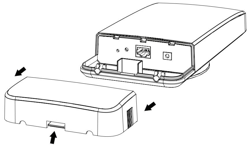
Physical Installation
Remove the bottom cover
Lift the release tab in the middle of the cover, then pull the cover off.
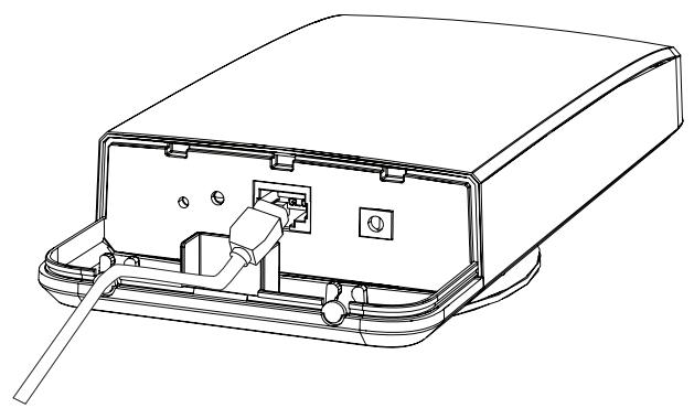
Connect an Ethernet cable
Connect an Ethernet cable (not included) to the Ethernet port.
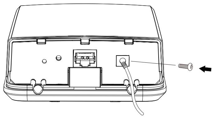
Connect the grounding wire
Use the grounding screw to attach the grounding wire.
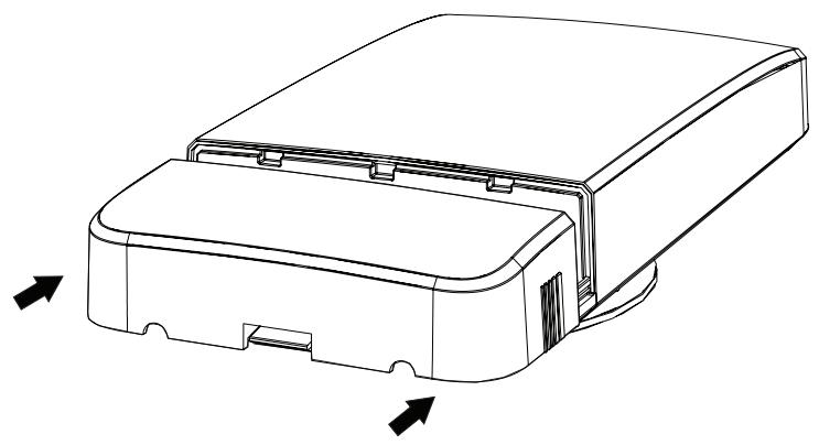
Reattach the bottom cover.
You may need to break off one of the plastic port covers to allow your cables to exit the AP.
Mounting the AP
The DAP-3320 supports the IP55 water/dustproof standard. It is recommended that you place the AP under a roof, shelter, or weatherproof container in severe weather environments. It is highly recommended that you configure and test your access point before mounting it.
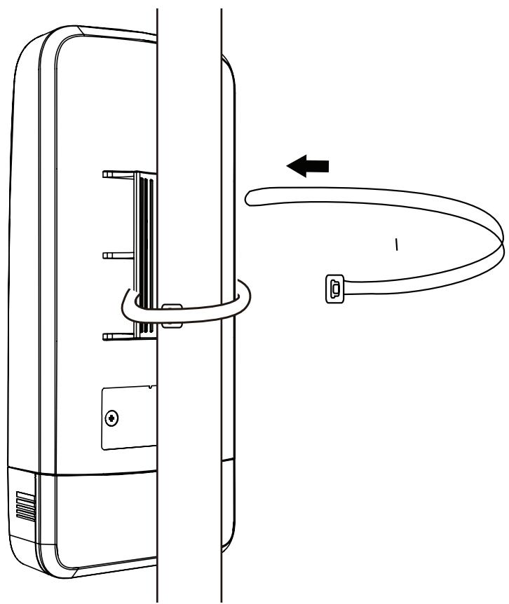
Mounting the AP to a Pole
Thread the plastic mounting ties through the back of the DAP-3320 and around the pole.
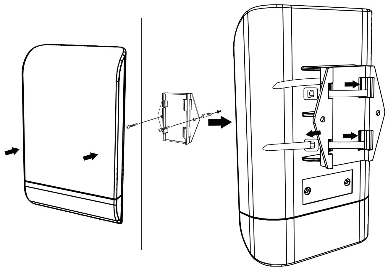
Mounting the AP to a Wall
Screw the wall mounting bracket into the wall, then attach the DAP-3320 to it. For extra security, you can thread the plastic mounting ties through the back of the DAP-3320 and the wall mounting bracket as shown.
Connect to your Network
To power the access point, you can use one of the following 2 methods:
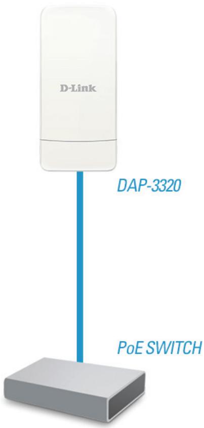
Method 1 - Powered by PoE Switch
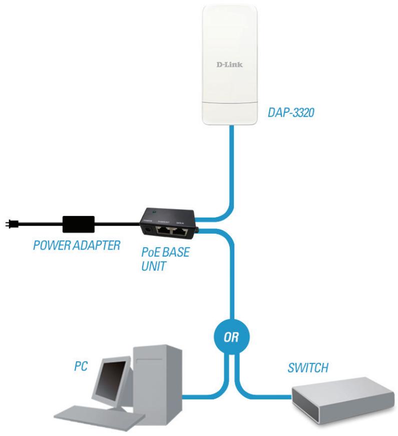
Method 2 - Powered by PoE Injector
Method 1 - Powered by PoE Switch
- Connect one end of your Ethernet cable into the LAN (PoE) port on the DAP-3320 and then connect the other end to your PoE switch.
Method 2 - Powered by PoE Injector
If you wish to power the DAP-3320 without a PoE switch, we suggest you use a PoE injector, such as a DPE-101Gl.
- Connect one end of an Ethernet cable into the DATA IN port on the PoE injector and the other end into a port on your switch, router, or computer.
- Connect one end of a different Ethernet cable into the P+DATA OUT port on the PoE injector and the other end into the LAN (PoE) port on the DAP-3320 access point.
- Connect the supplied power adapter to the POWER IN connector on the PoE Injector.
- Plug the power adapter into a power outlet.
Wireless Installation Considerations
The D-Link DAP-3320 Wireless PoE Outdoor Access point lets you access your network using a wireless connection from virtually anywhere within the operating range of your wireless network. Keep in mind, however, that the number, thickness and location of walls, ceilings, or other objects that the wireless signals must pass through, may limit the range. Typical ranges vary depending on the types of materials and background RF (radio frequency) noise in your home or business. The key to maximizing wireless range is to follow these basic guidelines:
- Keep the number of walls and ceilings between the D-Link access point and other network devices to a minimum. Each wall or ceiling can reduce your adapter's range from 3-90 feet (1-30 meters). Position your devices so that the number of walls or ceilings is minimized.
- Be aware of the direct line between network devices. A wall that is 1.5 feet thick (.5 meters), at a 45-degree angle appears to be almost 3 feet (1 meter) thick. At a 2-degree angle it looks over 42 feet (14 meters) thick. Position devices so that the signal will travel straight through a wall or ceiling (instead of at an angle) for better reception.
- Building materials make a difference. A solid metal door or aluminum studs may have a negative effect on range. Try to position access points, wireless access points, and computers so that the signal passes through drywall or open doorways. Materials and objects such as glass, steel, metal, walls with insulation, water (fish tanks), mirrors, file cabinets, brick, and concrete will degrade your wireless signal.
- Keep your product away (at least 3-6 feet or 1-2 meters) from electrical devices or appliances that generate RF noise.
- If you are using 2.4 Ghz cordless phones or X-10 (wireless products such as ceiling fans, lights, and home security systems), your wireless connection may degrade dramatically or drop completely. Make sure your 2.4 Hz phone base is as far away from your wireless devices as possible. The base transmits a signal even if the phone is not in use.
Four Operational Modes
| Operation Mode (Only supports 1 mode at a time) | Function |
| Access Point (AP) | Create a wireless LAN |
| WDS with AP | Wirelessly connect multiple networks while still functioning as a wireless AP |
| WDS | Wirelessly connect multiple networks |
| Wireless Client | AP acts as a wireless network adapter for your Ethernet-enabled device |
Configuration
This section will show you how to configure your new D-Link Wireless PoE Outdoor Access point using the web-based configuration utility.
Web-based Configuration Utility
If you wish to change the default settings or optimise the performance of the DAP-3320, you may use the web-based configuration utility.
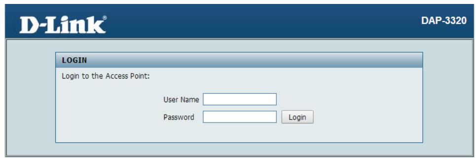
To access the configuration utility, open a web browser such as Internet Explorer and enter http://192.168.0.50
Type admin and then enter your password. Leave the password blank by default.
If you get a Page Cannot be Displayed error, please refer to "Troubleshooting" on page 106 for assistance.

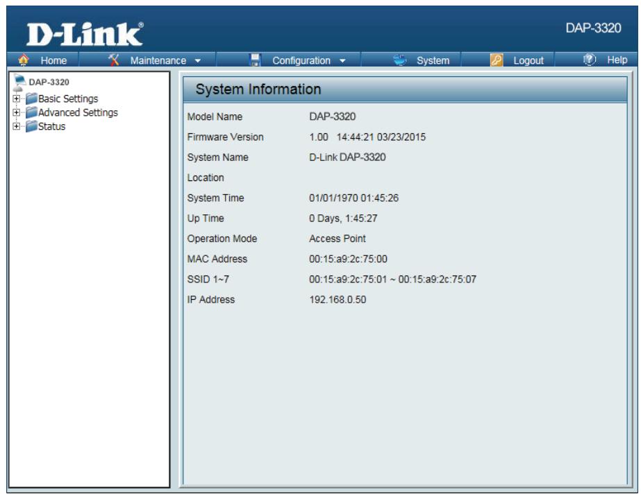
After successfully logging into the DAP-3320, the following screen will appear:
Save and Activate Settings
When making changes on most of the configuration screens in this section, use the Save button at the bottom of each screen to save (not activate) your configuration changes.
You may change settings to multiple pages before activating. Once you are finished, click the Configuration button located at the top of the page and then click Save and Activate.

Basic Settings
Wireless
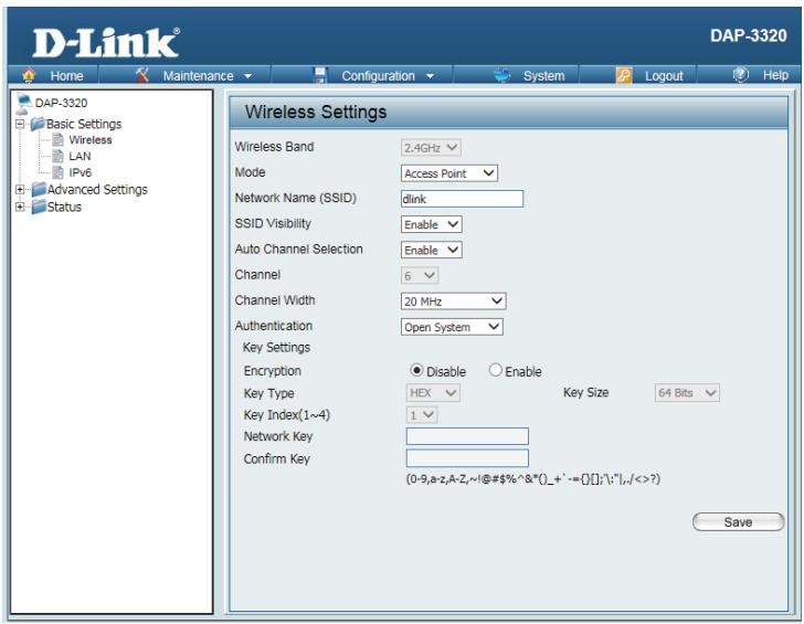
Access Point mode
Wireless Select 2.4 Ghz from the drop-down menu.
Band:
Mode: Select Access Point from the drop-down menu.
The other three choices are WDS with AP, WDS, and wireless Client.
Network Service Set Identifier (SSID) is the name designated for a specific wireless
Name local area network (WLAN). The SSID's factory default setting is dlink. The
(SSID): SSD can be easily changed to connect to an existing wireless network or to establish a new wireless network. The SSD can be up to 32 characters and is case-sensitive.
SSID Enable or Disable SSID visibility. Enabling this feature broadcasts the SSID
Visibility: across the network, thus making it visible to all network users. This feature is enabled by default.
Auto Enabling this feature automatically selects the channel that provides the
Channel best wireless performance. Enable is set by default. The channel selection
Selection: process only occurs when the AP is booting up.
Channel: All devices on the network must share the same channel. To change the channel, first toggle the Auto Channel Selection setting to Disable, and then use the drop-down menu to make the desired selection.
Note: The wireless adapters will automatically scan and match the wireless settings.
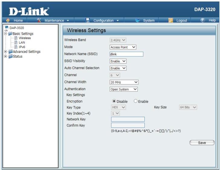
Channel Allows you to select the channel width you would like to operate in. Select
Width: 20 MHz if you are not using any 802.11n wireless clients. Auto 20/40 MHz allows you to connect to both 802.11n and 802.11b/g wireless devices on your network.
Authentication: Use the drop-down menu to choose Open System, Shared Key, WPA-Personal, WPA-Enterprise, or 802.11x.
Select Open System to communicate the key across the network.
Select Shared Key to limit communication to only those devices that share the same WEP settings. If multi-SSID is enabled, this option is not available.
Select WPA-Personal to secure your network using a password and dynamic key changes. No RADIUS server is required.
Select WPA-Enterprise to secure your network with the inclusion of a RADIUS server.
Select 802.1x to secure your network using 802.1x authentication.
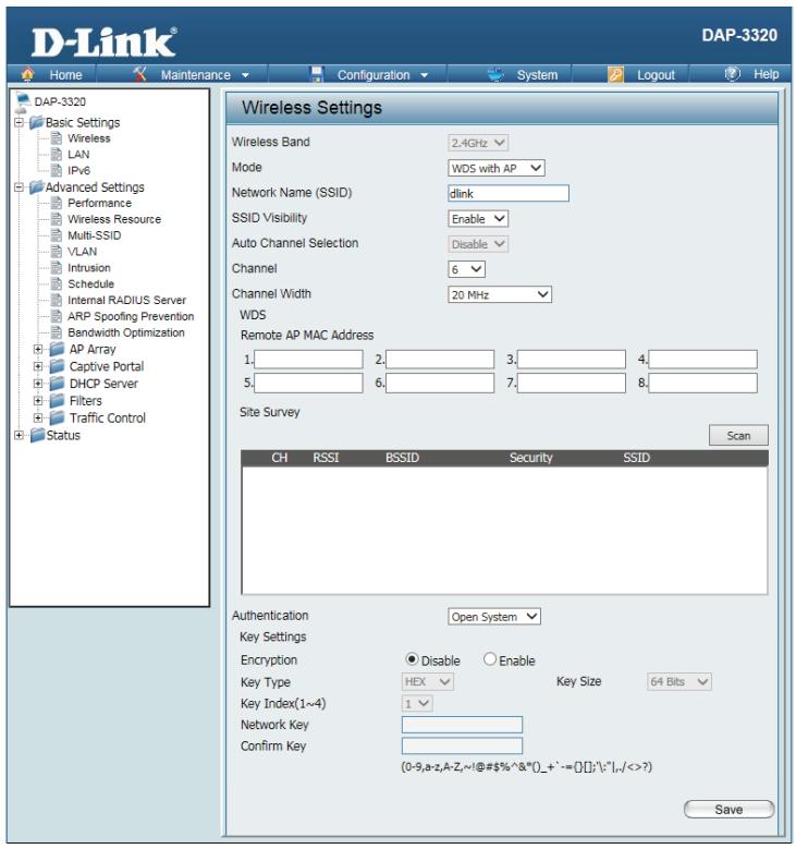
WDS with AP mode
In WDS with AP mode, the DAP-3320 wirelessly connects multiple networks while still functioning as a wireless AP.
Wireless Select 2.4 Ghz from the drop-down menu.
Band:
Mode: WDS with AP mode is selected from the drop-down menu.
The other three choices are Access Point, WDS, and wireless Client.
Network Service Set Identifier (SSID) is the name designated for a specific wireless
Name local area network (WLAN). The SSID's factory default setting is dlink. The
(SSID): SSD can be easily changed to connect to an existing wireless network or to establish a new wireless network.
SSID Enable or Disable SSID visibility. Enabling this feature broadcasts the SSID
Visibility: across the network, thus making it visible to all network users.
Auto Enabling this feature automatically selects the channel that will provide the
Channel best wireless performance. This feature is not supported in WDS with AP
Selection: mode. The channel selection process only occurs when the AP is booting up.
Channel: To change the channel, use the drop-down menu to make the desired selection. (Note: The wireless adapters will automatically scan and match the wireless settings.)
Channel Indicates whether the device is capable of 20 MHz operation only or both
Width: 20 MHz and 40 MHz operation.
Remote AP Enter the MAC addresses of the APs on your network that will serve as bridges
MAC Address: to wirelessly connect multiple networks.
Site Survey: Click on the Scan button to search for available wireless networks, then click on the available network that you want to connect with.
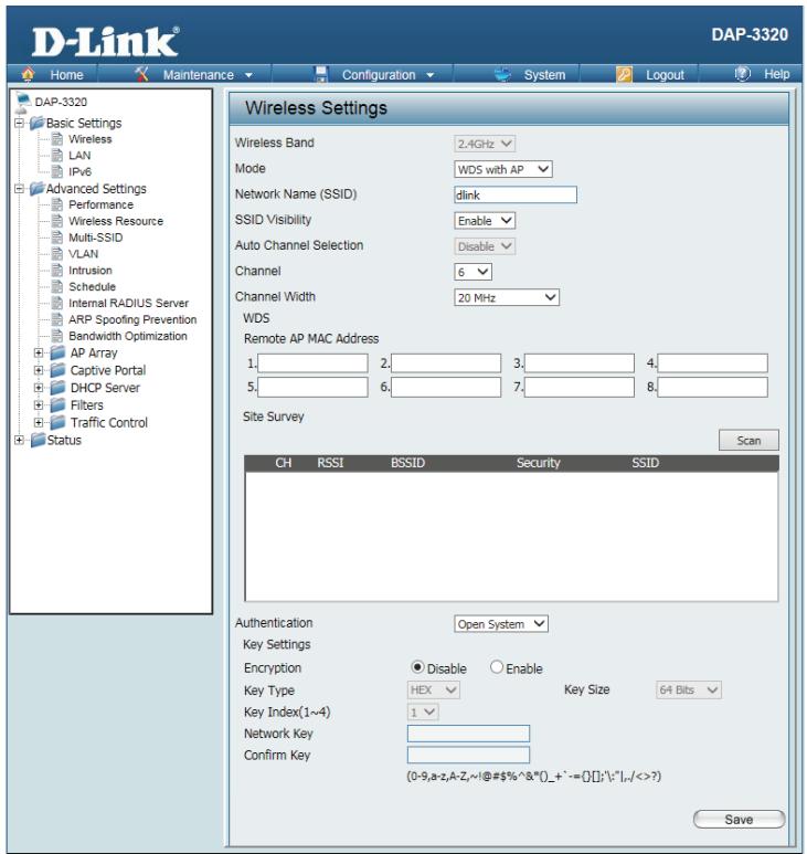
Authentication: Use the drop-down menu to choose Open System or WPA-Personal.
Select Open System to communicate the key across the network.
Select WPA-Personal to secure your network using a password and dynamic key changes. No RADIUS server is required.
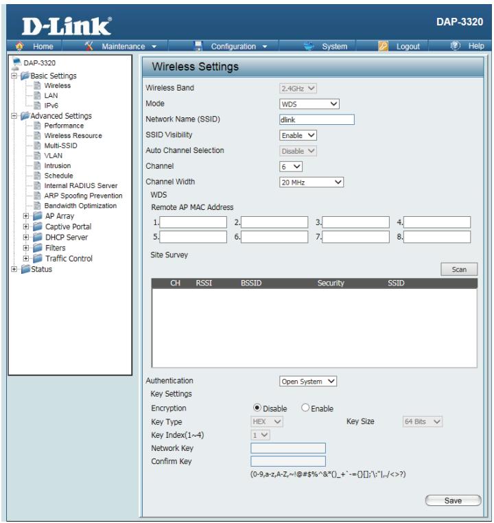
WDS mode
In WDS mode, the DAP-3320 wirelessly connects multiple networks, without functioning as a wireless AP.
Wireless Select 2.4 Ghz from the drop-down menu.
Band:
Mode: WDS is selected from the drop-down menu.
The other three choices are Access Point, WDS with AP, and wireless Client.
Network Service Set Identifier (SSID) is the name designated for a specific wireless Name local area network (WLAN). TheSSID's factory default setting is dlink. The
(SSID): SSD can be easily changed to connect to an existing wireless network or to establish a new wireless network.
SSID Enable or Disable SSID visibility. Enabling this feature broadcasts the SSID
Visibility: across the network, thus making it visible to all network users.
Auto Enabling this feature automatically selects the channel that will provide the Channel best wireless performance. This feature is not supported in WDS with AP
Selection: mode. The channel selection process only occurs when the AP is booting up.
Channel: To change the channel, use the drop-down menu to make the desired selection. (Note: The wireless adapters will automatically scan and match the wireless settings.)
Channel Indicates whether the device is capable of 20 MHz operation only or both
Width: 20 MHz and 40 MHz operation.
Remote Enter the MAC addresses of the APs on your network that will serve as bridges
AP MAC to wirelessly connect multiple networks.
Address:
Site Survey: Click on the Scan button to search for available wireless networks, then click on the available network that you want to connect with.
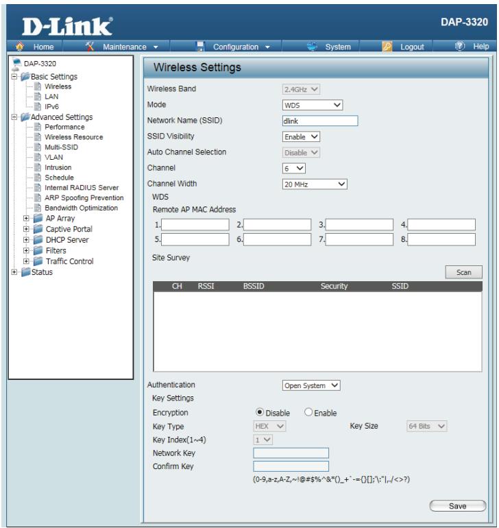
Authentication: Use the drop-down menu to choose Open System or WPA-Personal.
Select Open System to communicate the key across the network.
Select WPA-Personal to secure your network using a password and dynamic key changes. No RADIUS server is required.
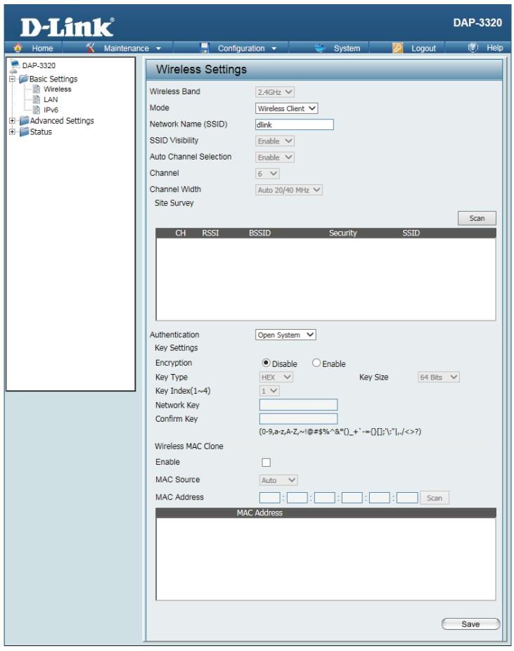
Wireless Client mode
Wireless Select 2.4 Ghz from the drop-down menu.
Band:
Mode: Wireless Client is selected from the drop-down menu.
The other three choices are Access Point, WDS with AP, and WDS.
Network Service Set Identifier (SSID) is the name designated for a specific wireless
Name local area network (WLAN). The SSID's factory default setting is dlink. The
(SSID): SSD can be easily changed to connect to an existing wireless network or to establish a new wireless network.
SSID Enable or Disable SSID visibility. Enabling this feature broadcasts the SSID
Visibility: across the network, thus making it visible to all network users. Disabling SSID is not supported in Wireless Client mode.
Auto Enabling this feature automatically selects the channel that will provide
Channel the best wireless performance. This feature is automatically enabled in
Selection: Wireless Client mode. The channel selection process only occurs when the AP is booting up.
Channel: To change the channel, use the drop-down menu to make the desired selection. (Note: The wireless adapters will automatically scan and match the wireless settings.)
Channel Indicates whether the device is capable of 20 MHz operation only or both
Width: 20 MHz and 40 MHz operation.
Click on the Scan button to search for available wireless networks, then click on the available network that you want to connect with.
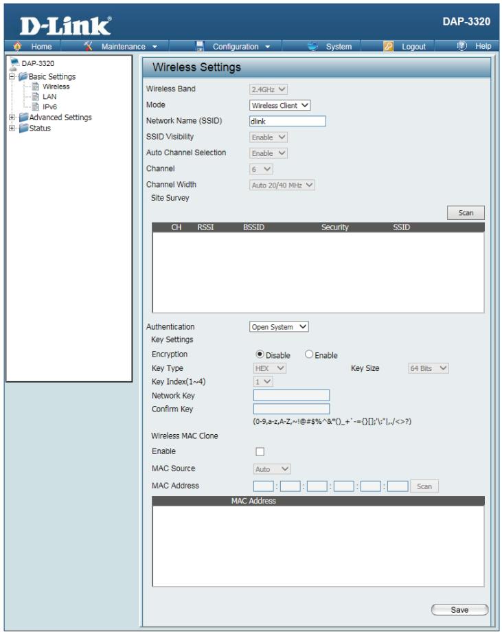
Authentication: Use the drop-down menu to choose Open System or WPA-Personal.
Select Open System to communicate the key across the network.
Select WPA-Personal to secure your network using a password and dynamic key changes. No RADIUS server is required.
Wireless Mac Check to enable clone MAC. This feature will allow you to change the MAC
Clone Enable: address of the access point to the MAC address of a client.
MAC Source: Select the MAC source from the drop-down menu.
MAC Address: Enter the MAC address that you would like to assign to the access point.
Authentication Types
Each of the wireless modes on the DAP-3320 support different types of wireless encryption security standards. Not every mode supports all types of encryption.
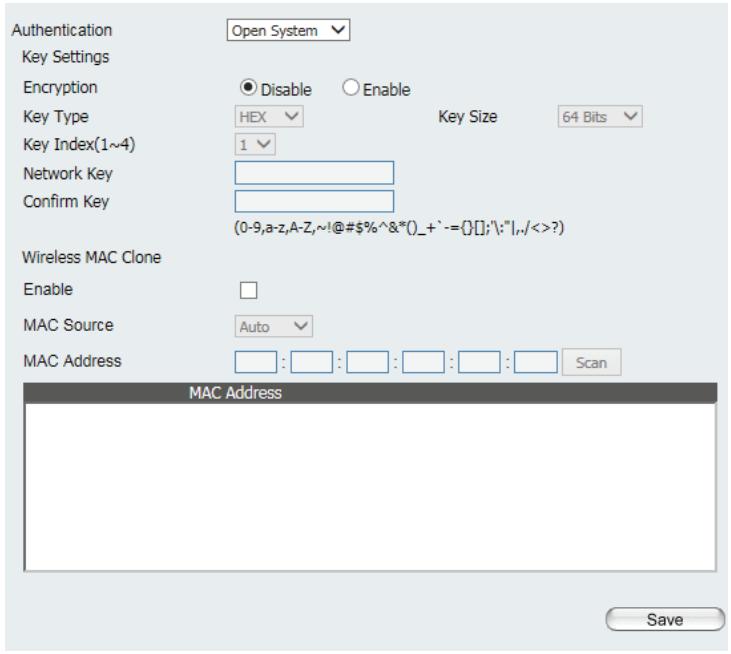
Open System/Shared Key Authentication
All wireless modes on the DAP-3320 support Open System/Shared Key Authentication.
Encryption Use the radio button to disable or enable encryption.
Key Type: Select HEX or ASCII*.
Key Size: Select 64 Bits or 128 Bits.
Key Index Select the 1st through the 4th key to be the active key: (1-4):
Key: Input up to four keys for encryption. You will select one of these keys in the Key Index drop-down menu.
*Hexadecimal (HEX) digits consist of the numbers 0-9 and the letters A-F.
**ASCII (American Standard Code for Information Interchange) is a code that represents English letters using numbers ranging from 0-127.
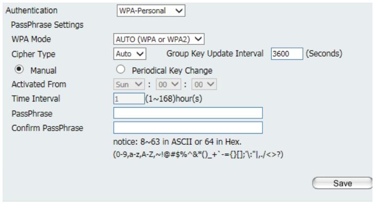
WPA/WPA2-Personal Authentication
WPA/WPA2 Personal Authentication can be enabled for Access Point, WDS with AP, WDS, and Wireless Client modes.
WPA Mode: When WPA-Personal is selected for Authentication type, you must also select a WPA mode from the drop-down menu: AUTO (WPA or WPA2), WPA2 Only, or WPA Only. WPA and WPA2 use different algorithms. AUTO (WPA or WPA2) allows you to use both WPA and WPA2.
Cipher Type: When you select WPA-Personal, you must also select AUTO, AES, or TKIP from the drop-down menu.
Group Key Select the interval during which the group key will be valid. The default value Update: of 3600 is recommended.
Select Manual to enter your key (PassPhrase).
You can select Periodical Key Change to have the access point automatically change your PassPhrase.
Periodical Enter the Activate From time and the time in hours to change the key. Key Change:
PassPhrase: When you select WPA-Personal, please enter a PassPhrase in the corresponding field.
Confirm Type the passphrase again to guard against typos. PassPhrase:
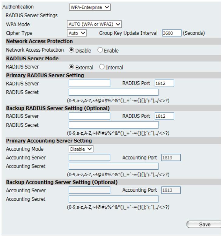
WPA/WPA2-Enterprise Authentication
WPA/WPA2 Enterprise Authentication can only be enabled for Access Point mode.
WPA Mode: When WPA-Enterprise is selected, you must also select a WPA mode from the drop-down menu: AUTO (WPA or WPA2), WPA2 Only, or WPA Only. WPA and WPA2 use different algorithms. AUTO (WPA or WPA2) allows you to use both WPA and WPA2.
Cipher When WPA-Enterprise is selected, you must also select a cipher type from Type: the drop-down menu: Auto, AES, or TKIP.
Group Key Select the interval during which the group key will be valid. The recommended Update value is 3600. A lower interval may reduce data transfer rates.
Interval:
Network Enable or disable Microsoft Network Access Protection. Access
Protection:
RADIUS Enter the IP address of the RADIUS server. Server:
RADIUS Enter the RADIUS port. Port:
RADIUS Enter the RADIUS secret. Secret:
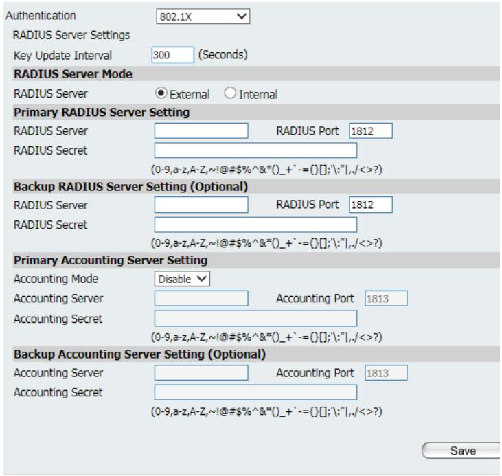
802.1x Authentication
802.1x Authentication can only be enabled for Access Point mode.
Key Update Select the interval during which the group key will be valid (300 is the Interval: recommended value). A lower interval may reduce data transfer rates.
RADIUS Enter the IP address of the RADIUS server.
Server:
RADIUS Enter the RADIUS port.
Port:
RADIUS Enter the RADIUS secret.
Secret:
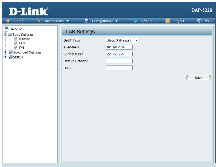
LAN
LAN is short for Local Area Network. This is considered your internal network. These are the IP settings of the LAN interface for the DAP-3320. These settings may be referred to as private settings. You may change the LAN IP address if needed. The LAN IP address is private to your internal network and cannot be seen on the Internet.
Get IP From: Static IP (Manual) is chosen here. Choose this option if you do not have a DHCP server in your network, or if you wish to assign a static IP address to the DAP-3320. When Dynamic IP (DHCP) is selected, the other fields here will be grayed out. Please allow about two minutes for the DHCP client to be functional once this selection is made.
IP Address: The default IP address is 192.168.0.50. Assign a static IP address that is within the IP address range of your network.
Subnet Enter the subnet mask. All devices in the network must share the same Mask: subnet mask.
Default Enter the IP address of the gateway in your network. If there is a gateway in Gateway: your network, please enter an IP address within the range of your network.
DNS: Enter the DNS IP address used here.
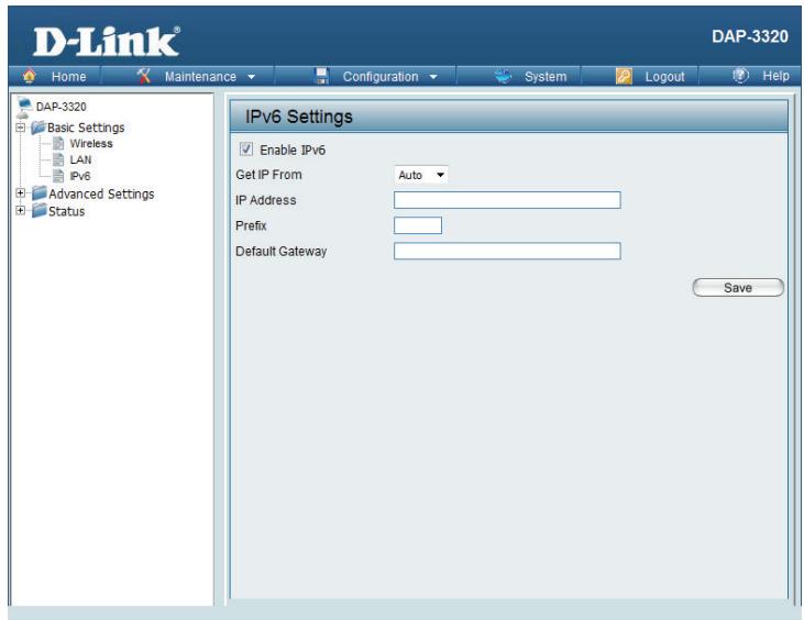
IPv6
Enable IPv6: Check to enable the IPv6.
Get IP From: Auto is the default option. The DAP-3320 will get an IPv6 address automatically or use Static to set IPv6 address manually. When Auto is selected, the other fields here will be grayed out.
IP Address: Enter the LAN IPv6 address used here.
Prefix: Enter the LAN subnet prefix length value used here.
Default Enter the LAN default gateway IPv6 address used here. Gateway:
Advanced Settings
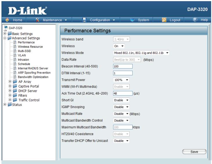
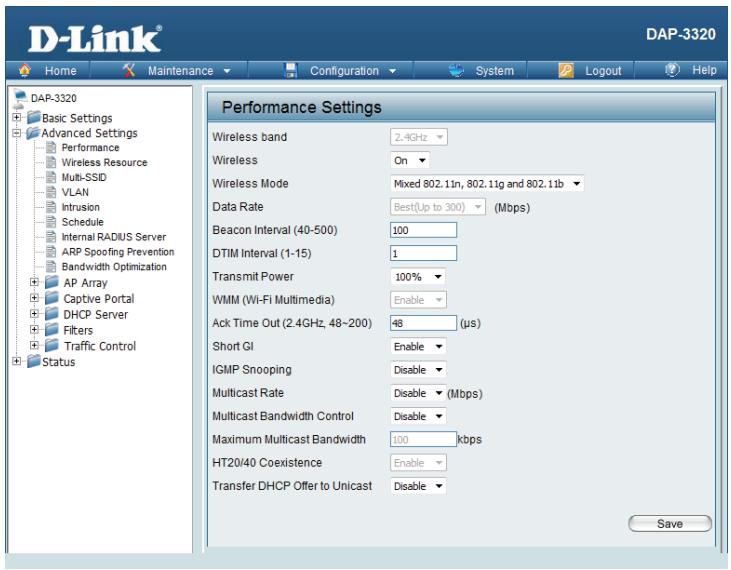
Performance
Wireless: Use the drop-down menu to turn the wireless function On or Off.
Wireless The different combination of clients that can be supported include Mixed
Mode: 802.11n, 802.11g and 802.11b, Mixed 802.11g and 802.11b and 802.11n Only. Please note that when backwards compatibility is enabled for legacy (802.11g/b) clients, degradation of 802.11n wireless performance is expected.
Data Rate*: Indicate the base transfer rate of wireless adapters on the wireless LAN. The AP will adjust the base transfer rate depending on the base rate of the connected device. If there are obstacles or interference, the AP will step down the rate. This option is enabled in Mixed 802.11g and 802.11b mode. The choices available are Best (Up to 54), 54, 48, 36, 24, 18, 12, 9, 6, 11, 5.5, 2 or 1.
Beacon Beacons are packets sent by an access point to synchronize a Interval (25- wireless network. Specify a value in milliseconds. The default (100) is
500): recommended. Setting a higher beacon interval can help to save the power of wireless clients, while setting a lower one can help a wireless client connect to an access point faster.
DTM Select a Delivery Traffic Indication Message setting between 1 and 15.
Interval The default value is 1. DTIM is a countdown informing clients of the next
(1-15): window for listening to broadcast and multicast messages.
Transmit This setting determines the power level of the wireless transmission.
Power: Transmitting power can be adjusted to eliminate overlapping of wireless area coverage between two access points where interference is a major concern. For example, if wireless coverage is intended for half of the area, then select 50% as the option. Use the drop-down menu to select 100% , 50% , 25% , or 12.5% .
*Maximum wireless signal rate derived from IEEE Standard 802.11n and 802.11g specifications. Actual data throughput may vary. Network conditions and environmental factors, including volume of network traffic, building materials and construction, and network overhead can lower actual data throughput rate.
WMM (Wi-Fi) WMM stands for Wi-Fi Multimedia. Enabling this feature will improve the
Multimedia): user experience for audio and video applications over a Wi-Fi network.
Ack Time Out To effectively optimize throughput over long distance links, enter a value
(2.4 GHZ, for Acknowledgement Time Out from 64 to 200 microseconds in the 2.4
64~200): GHz in the field provided.
Short Gl: Select Enable or Disable. Enabling a short guard interval can increase throughput. However, be aware that it can also increase the error rate in some installations due to increased sensitivity to radio-frequency installations.
IGMP Select Enable or Disable. Internet Group Management Protocol allows
Snooping: the AP to recognize IGMP queries and reports sent between routers and an IGMP host (wireless STA). When IGMP snooping is enabled, the AP will forward multicast packets to an IGMP host based on IGMP messages passing through the AP.
Multicast Rate: Select the multicast rate for 2.4G band.
Multicast Adjust the multicast packet data rate here. The multicast rate is supported
Bandwidth in AP mode and WDS with AP mode, including Multi-SSIDs.
Control:
Maximum Set the multicast packets maximum bandwidth pass through rate from
Multicast the Ethernet interface to the Access Point.
Bandwidth :
HT20/40 Enable this option to reduce interference from other wireless networks in
Coexistence: your area. If the channel width is operating at 40 MHz and there is another
wireless network's channel over-lapping and causing interference, the
Access Point will automatically change to 20 MHz.
Transfer Enable to transfer the DHCP Offer to Unicast from LAN to WLAN, it is
DHCP Offer recommended to enable this function if stations number is larger than 30.
to Unicast :
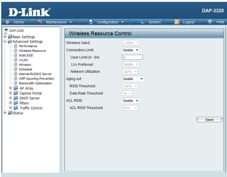
Wireless Resource Control
The Wireless Resource Control window is used to configure the wireless connection settings so that devices can detect and connect to the Access Point with the strongest signal.
Wireless band: Select 2.4 Ghz.
Connection Limit: Select Enable or Disable. This is an option for load balancing. This determines whether to limit the number of users accessing this device. The exact number is entered in the User Limit field below. This feature allows the user to share the wireless network traffic and the client using multiple APs. If this function is enabled and when the number of users exceeds this value, or the network utilization of this AP exceeds the percentage that has been specified, the DAP-3320 will not allow clients to associate with the AP.
User Limit: Set the maximum amount of users that are allowed access (zero to 64 users) to the device using the specified wireless band. The default setting is 20.
11n Use the drop-down menu to Enable the 11n Preferred function. The wire- less clients with 802.11n protocol will have higher priority to connect to the device.
Network Set the maximum utilization of this access point. The DAP-3320 will not
Utilization: allow any new clients to associate with the AP if the utilization exceeds
the specified value. Select a utilization percentage between 100% 80% 60% 40% 20% or 0% . When this network utilization threshold is reached,
the device will pause for one minute to allow network congestion to dissi
sipate.
Aging out: Use the drop-down menu to select the criteria of disconnecting the wireless clients. Available options are RSSI and Data Rate.
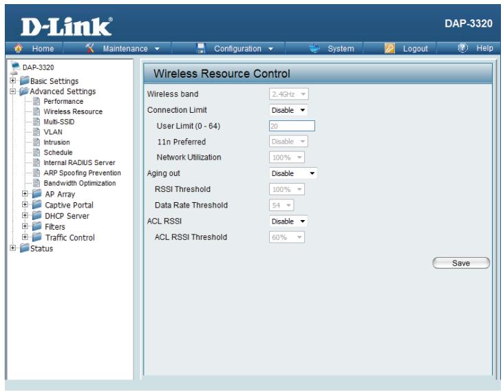
RSSI When RSSI is selected in the Aging out drop-down menu, select the percentage of RSSI here. When the RSSI of wireless clients is lower than the specified percentage, the device disconnects the wireless clients.
Data Rate When Data Rate is selected in the Aging out drop-down menu, select the threshold of data rate here. When the data rate of wireless clients is lower than the specified number, the device disconnects the wireless clients.
ACL RSSI: Use the drop-down menu to Enable the function. When enabled, the device denies the connection request from the wireless clients with the RSSI lower than the specified threshold below.
ACL RSSI Set the ACL RSSI Threshold. Threshold:
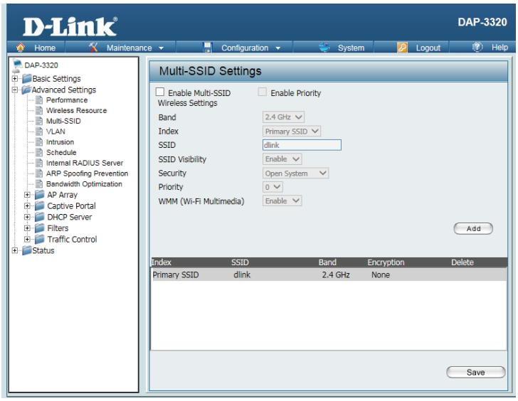
Multi-SSID
The device supports up to four multiple Service Set Identifiers. In the Basic > Wireless section, you can set the Primary SSID. The SSID's factory default setting is dlink. The SSID can be easily changed to connect to an existing wireless network or to establish a new wireless network.
Enable Check to enable support for multiple SSIDs. Multi-SSID:
Band: This read-only value is the current band setting.
Index: You can select up to three multi-SSIDs. With the Primary SSID, you have a total of four multi-SSIDs.
SSID Service Set Identifier (SSID) is the name designated for a specific wireless local area network (WLAN). TheSSID's factory default setting is dlink. TheSSID can be easily changed to connect to an existing wireless network or to establish a new wireless network.
SSID Enable or Disable SSID visibility. Enabling this feature broadcasts the SSID Visibility: across the network, thus making it visible to all network users.
Security: The Multi-SSID security can be Open System, WPA-Personal, WPA-Enterprise, or 802.1x. For a detailed description of the Open System parameters, please go to page 26. For a detailed description of the WPA-Personal parameters, please go to page 27. For a detailed description of the WPA-Enterprise parameters, please go to page 28. For a detailed description of the 802.1x parameters, please go to page 29.
Priority: Check the Enable Priority box at the top of this window to enable. Select the priority from the drop-down menu.
WMM (Wi-Fi Select Enable or Disable.
Multimedia):
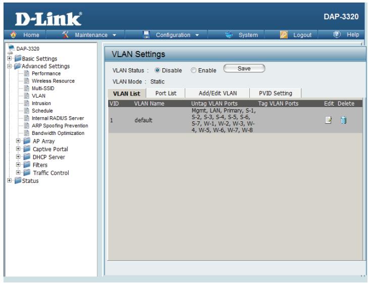
VLAN VLAN List
The DAP-3320 supports VLANs. VLANs can be created with a Name and VID. Mgmt (TCP stack), LAN, Primary Multiple SSID, and WDS connection can be assigned to VLANs as they are physical ports. Any packet which enters the DAP-3320 without a VLAN tag will have a VLAN tag inserted with a PVID.
The VLAN List tab displays the current VLANs.
VLAN Use the radio button to toggle between Enable or Disable. Next, go to the Status: Add/Edit VLAN tab to add or modify an item on the VLAN List tab.
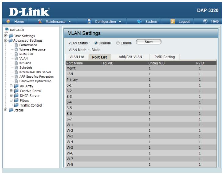
Port List
The Port List tab displays the current ports. If you want to configure guest and internal networks on a Virtual LAN (VLAN), the switch and DHCP server you are using must also support VLANs. As a prerequisite step, configure a port on the switch for handling VLAN tagged packets as described in the IEEE 802.1Q standard.
VLAN Use the radio button to toggle to Enable. Next, go to the Add/Edit VLAN Status: tab to add or modify an item on the VLAN List tab.
Port Name: The name of the port is displayed in this column.
Tag VID: The Tagged VID is displayed in this column.
Untag VID: The Untagged VID is displayed in this column.
PVID: The Port VLAN Identifier is displayed in this column.
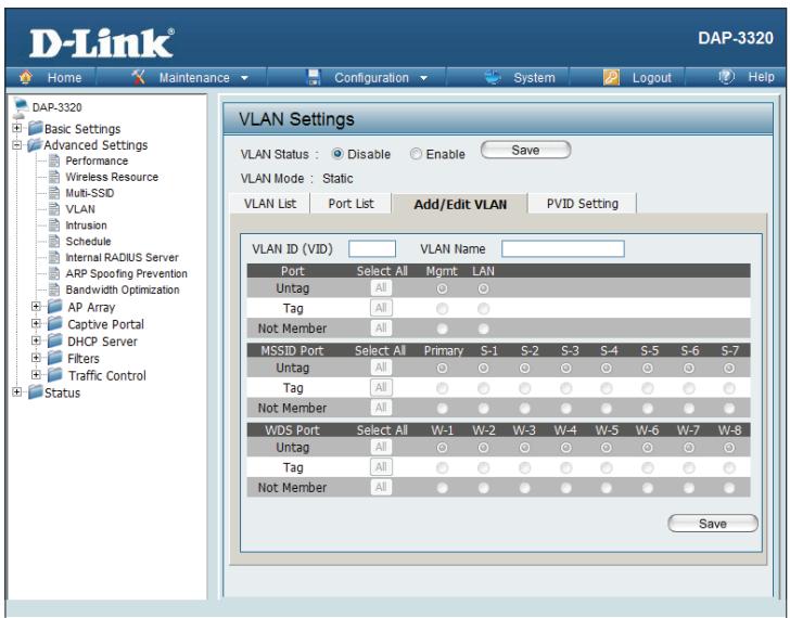
Add/Edit VLAN
The Add/Edit VLAN tab is used to configure VLANs. Once you have made the desired changes, click the Save button to let your changes take effect.
VLAN Use the radio button to toggle to Enable.
Status:
VLAN ID: Provide an ID number between 1 and 4094 for the Internal VLAN.
VLAN Enter the VLAN to add or modify.
Name:
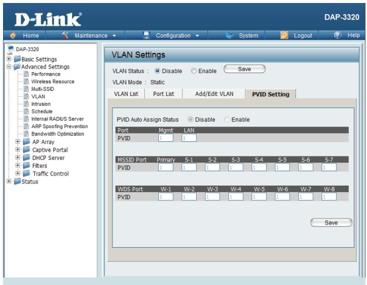
PVID Setting
The PVID Setting tab is used to enable/disable the Port VLAN Identifier Auto Assign Status as well as to configure various types of PVID settings. Click the Save button to let your changes take effect.
VLAN Status: Use the radio button to toggle between Enable and Disable.
PVID Auto Use the radio button to toggle PVID auto assign status to Enable. Assign Status:
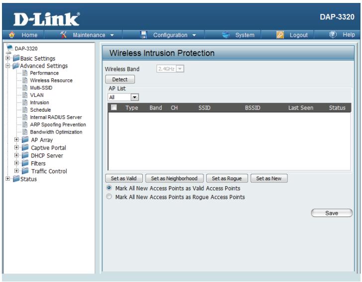
Intrusion
The Wireless Intrusion Protection window is used to set APs as All, Valid, Neighborhood, Rogue, and New. Click the Save button to let your changes take effect.
AP List: The choices include All, Valid, Neighbor, Rogue, and New.
Detect: Click this button to initiate a scan of the network.
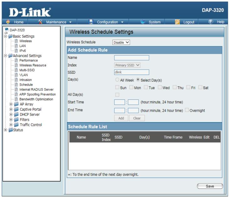
Schedule
The Wireless Schedule Settings window is used to add and modify scheduling rules on the device. Click the Save button to let your changes take effect.
Wireless Use the drop-down menu to enable the device's scheduling feature.
Schedule:
Name: Enter a name for the new scheduling rule in the field provided.
Index: Select the SSID the schedule will apply to from the drop-down menu.
SSID: Enter the name of your wireless network (SSID).
Day(s): Toggle the radio button between All Week and Select Day(s). If the second option is selected, check the specific days you want to apply the rule to.
All Day(s): Check this box to have your settings apply 24 hours a day.
Start Time: Enter the start time for your rule. If you selected All Day, this option will be greyed out.
End Time: Enter the end time for your rule.
Add: Click to add the rule to the list.
Schedule This section will display the list of created schedules.
Rule List:
Save: Click the Save button to save your created rules.
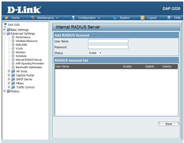
Internal RADIUS Server
The DAP-3320 features a built-in RADIUS server. Once you have finished adding a RADIUS account, click the Save button to have your changes take effect. The newly-created account will appear in this RADIUS Account List. The radio buttons allow the user to enable or disable the RADIUS account. Click the icon in the delete column to remove the RADIUS account. We suggest you limit the number of accounts to under 30.
User Name: Enter a name to authenticate user access to the internal RADIUS server.
Password: Enter a password to authenticate user access to the internal RADIUS server. The length of your password should be 8~64.
Status: Toggle the drop-down menu between Enable and Disable.
RADIUS Displays the list of users. Account List:
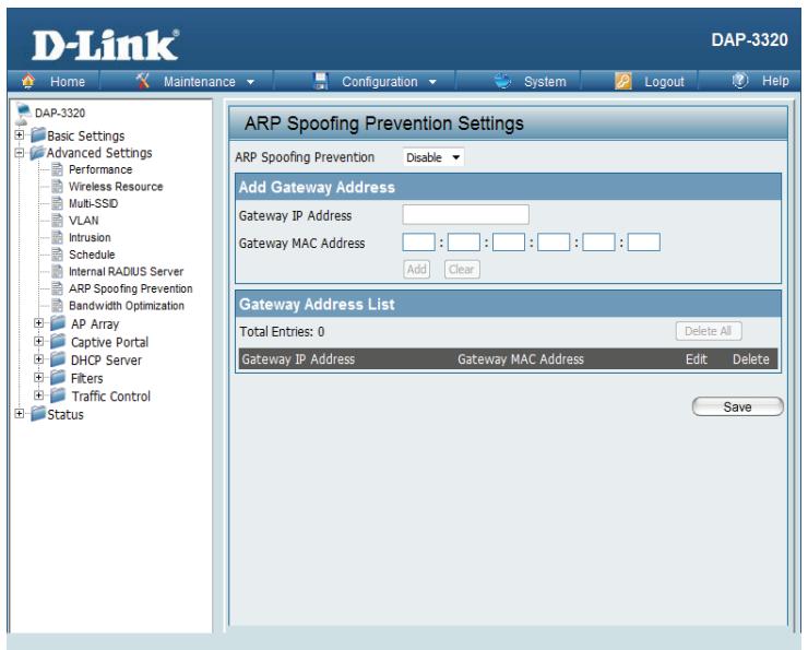
ARP Spoofing Prevention Settings
The ARP Spoofing Prevention feature allows users to add IP/MAC address mapping to prevent ARP spoofing attacks.
ARP This check box allows you to enable the ARP spoofing prevention function.
Spoofing
Prevention:
Gateway Enter a gateway IP address.
IP Address:
Gateway Enter a gateway MAC address. MAC Address:
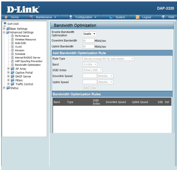
Bandwidth Optimization
The Bandwidth Optimization window allows the user to manage the bandwidth of the access point and adjust the bandwidth for various wireless clients. After inputting a Bandwidth Optimization rule, click the Add button. To discard a Bandwidth Optimization Rule setting, click the Clear button. Click the Save button to let your changes take effect.
Enable Use the drop-down menu to Enable the Bandwidth Optimization function. Bandwidth Optimization:
Downlink Enter the downlink bandwidth of the device in Mbits per second. Bandwidth:
Uplink Enter the uplink bandwidth of the device in Mbits per second. Bandwidth:
Rule Type: Use the drop-down menu to select the type that is applied to the rule. Available options are: Allocate average BW for each station, Allocate maximum BW for each station, Allocate different BW for 11 b/g/n stations, and Allocate specific BW for SSID.
Allocate AP will distribute average bandwidth for each client.
average BW for
each station:
Allocate Specify the maximum bandwidth for each connected client. Reserve certain maximum BW bandwidth for future clients. for each station:
Allocate The weight of 11 b/g/n client are 10% /20% /70% . AP will distribute different different BW bandwidth for 11 b/g/n clients. for b/g/n stations:
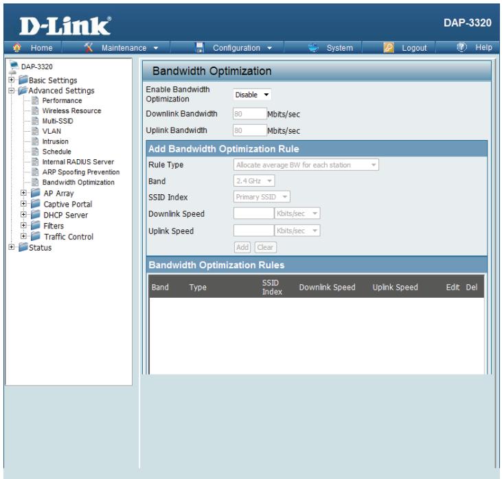
Allocate All clients share the total bandwidth.
specific BW
for SSID:
Band: Use the drop-down menu to toggle the wireless band 2.4 Ghz.
SSID Index: Use the drop-down menu to select the SSID for the specified wireless band.
Downlink Enter the downlink speed limit in either Kbits/sec or Mbits/sec for the rule. Speed:
Uplink Enter the upload speed limit in either Kbits/sec or Mbits/sec for the rule. Speed:
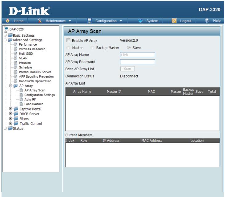
AP Array AP Array Scan
The AP Array window is used to create up to 32 APs on a local network to be organized into a single group in order to simplify management. Click the Save button to let your changes take effect. Central WiFiManager and AP Array are mutually exclusive functions.
Enable AP Select the check box to enable the AP array function. The three modes that Array: are available are Master, Backup Master, and Slave. APs in the same array will use the same configuration. The configuration will sync the Master AP to the Slave AP and the Backup Master AP when a Slave AP and a Backup Master AP join the AP array.
AP Array Enter an AP array name for the group here.
Name:
AP Array Enter an AP array password for the group here. This password must be the Password: same on all the APs in the group.
Scan AP Click this button to initiate a scan of all the available APs currently on the Array List: network.
Connection Display the AP array connection status.
Status:
AP Array This table displays the current AP array status for the following parameters: List: Array Name, Master IP, MAC, Master, Backup Master, Slave, and Total.
Current This table displays all the current array members. The DAP-3320 AP array Members: feature supports up to eight AP array members.
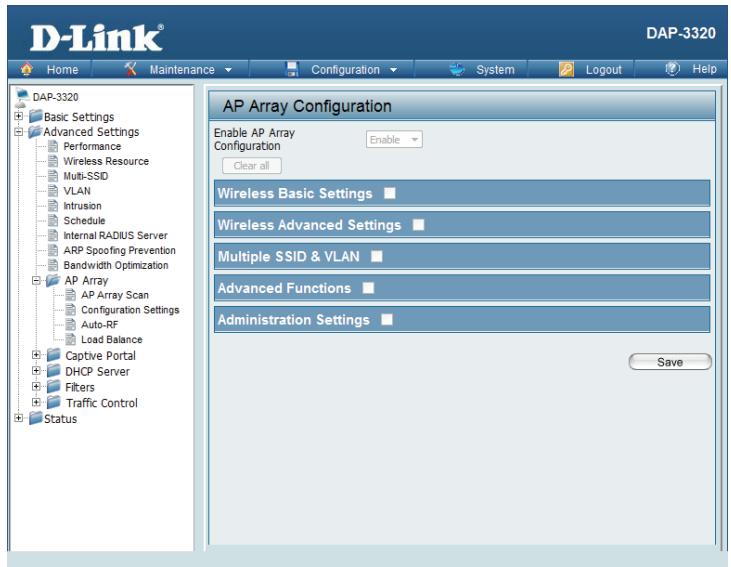
Configuration Settings
In the AP array configuration settings windows, users can specify which settings all the APs in the group will inherit from the master AP. Make the desired selections in this window and click the Save button to accept the changes.
Enable AP Select to Enable or Disable the AP array configure feature here.
Array
Configuration:
Wireless Select this option to specify the basic wireless settings that the APs in the Basic group will inherit.
Settings:
- Wireless Select this option to specify the advanced wireless settings that the APs in Advanced the group will inherit.
Settings:
Multiple Select this option to specify the multiple SSIDs and VLAN settings that the SSID & APs in the group will inherit.
VLAN:
Advanced Select this option to specify the other advanced settings that the APs in the Functions: group will inherit.
Administration Select this option to specify the administrative settings that the APs in the Settings: group will inherit.
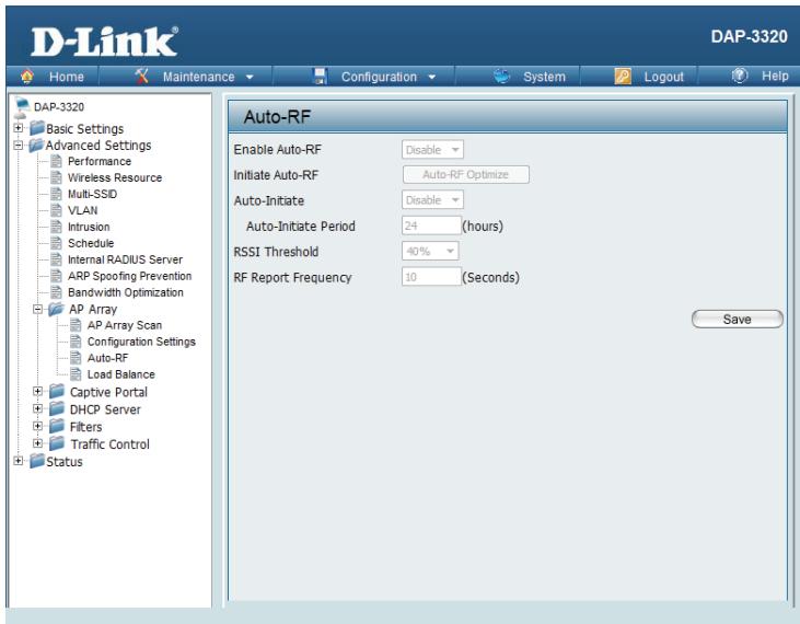
Auto-RF
In this windows, users can view and configure the automatic radio frequency settings as well as configure the the auto-initiate period and threshold values. Click the Save button to accept the changes made.
Enable: Select to Enable or Disable the auto-RF feature here.
Auto-RF:
Initiate Click the Auto-RF Optimize button to initiate the auto-RF optimization Auto-RF: feature.
Auto-Initiate: Select the Enable or Disable the auto-initiate feature here.
Auto-Initiate After enabling the auto-initiate option, the auto-initiate period value can Period: be entered here. This value must be between 1 and 24 hours.
RSSI Select the RSSI threshold value here. This value is listed in the drop-down Threshold: menu in increments of 10% from 10% to 100% .
RF Report Enter the RF report frequency value here. Frequency:
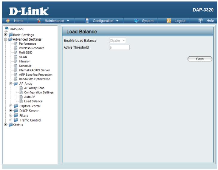
Load Balance
In this window, users can view and configure the AP array's load balancing settings. Click the Save button to accept the changes made.
Enable Load Select to Enable or Disable the load balance feature here.
Balance:
Active Enter the active threshold value here. Threshold:
Captive Portal Authentication
Captive Portal is a built-in web authentication server. When a client connects to an AP, the user's web browser will be redirected to a web authentication page. In this configuration option, administrators can view and configure the Captive Portal settings.
Web Redirection Only
After selecting Web Redirect Only as the Authentication Type, administrators can configure the redirection website URL that each wireless client will be redirected to upon connection to the network.
Session Enter the session timeout value here. This value can be from 1 to 1440
timeout minutes. By default, this value is 60 minutes.
(1-1440):
Band: Select 2.4 Ghz.
SSID Index: Select the SSID for this Authentication.
Authentication Select the captive portal encryption type here. Options to choose from
Type: are Web Redirect,Username/Password,Passcode,Remote RADIUS, LDAP and POP3.
Web Redirection State is automatically enabled when Web Redirect
Redirection Authentication is selected.
State:
URL Path: Select whether to use either HTTP or HTTPS here. After selecting either http://or https://, enter the URL of the website that will be used in the space provided.
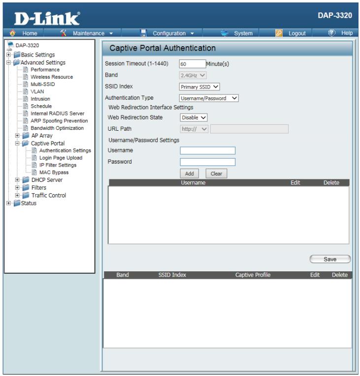
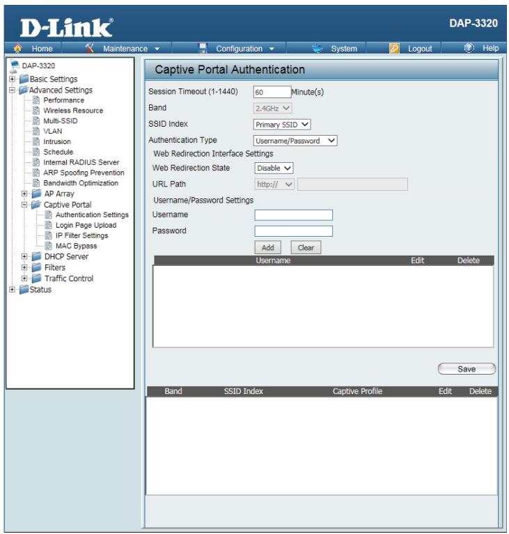
Username/Password
After selecting username/Password as the Authentication Type, administrators can configure theUsername and Password that each wireless client will be prompted for when requesting access to the network.
Session Enter the session timeout value here. This value can be from 1 to 1440
timeout minutes. By default, this value is 60 minutes.
(1-1440):
Band: Select 2.4 Ghz.
SSID Index: Select the SSID for this Authentication.
Authentication Select the captive portal encryption type here. Options to choose from are
Type: Web Redirect,Username/Password,Passcode,Remote RADIUS,LDAP and POP3.
Web Default is Disable or select Enable to enable the website redirection feature.
Redirection
State:
URL Path: Select whether to use either HTTP or HTTPS here. After selecting either http://or https://, enter the URL of the website that will be used in the space provided.
Username: Enter the username for the new account here.
Password: Enter the password for the new account here.
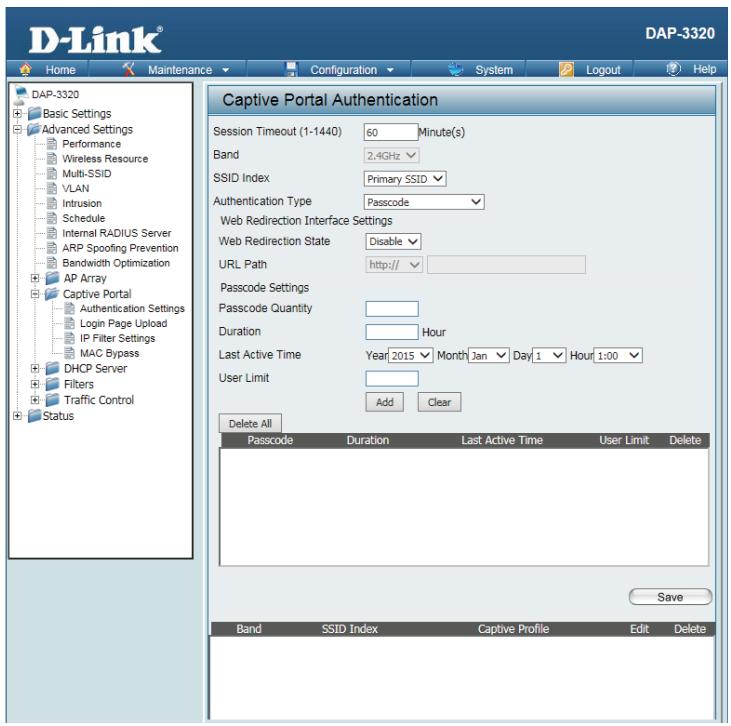
Passcode
After selecting Passcode as the Authentication Type, administrators can configure the Passcode that each wireless client will be prompted for when requesting access to the network. A passcode will be randomly generated upon clicking Add.
Session Enter the session timeout value here. This value can be from 1 to 1440
timeout minutes. By default, this value is 60 minutes.
(1-1440):
Band: Select 2.4 Ghz.
SSID Index: Select the SSID for this Authentication.
Authentication Select the captive portal encryption type here. Options to choose from are
Type: Web Redirect,Username/Password,Passcode,Remote RADIUS,LDAP and POP3.
Web Default is Disable or select Enable to enable the website redirection feature.
Redirection
State:
URL Path: Select whether to use either HTTP or HTTPS here. After selecting either http://or https://, enter the URL of the website that will be used in the space provided.
Passcode Enter the number of available passcodes
Quantity:
Duration: Enter the duration value, in hours, for this passcode.
Last Active Select the year, month, day, and hour when this passcode will expire.
Day:
User Limit: Enter the maximum amount of users that can use this passcode at the same time
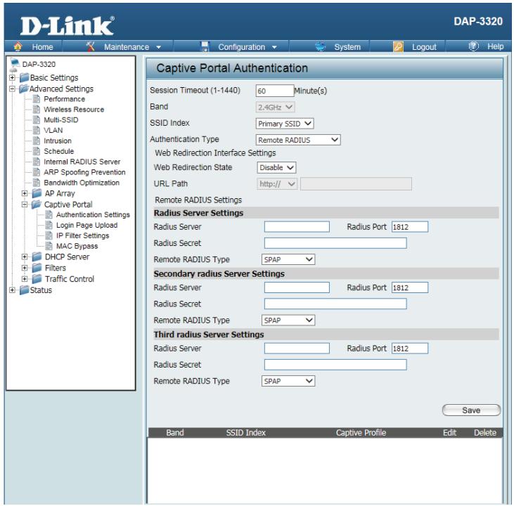
Remote RADIUS
After selecting Remote RADIUS as the Authentication Type, administrators can configure the Remote RADIUS authentication settings required to join the network.
Session Enter the session timeout value here. This value can be from 1 to 1440
timeout minutes. By default, this value is 60 minutes.
(1-1440):
Band: Select 2.4 Ghz.
SSID Index: Select the SSID for this Authentication.
Authentication Select the captive portal encryption type here. Options to choose from are
Type: Web Redirect,Username/Password,Passcode,Remote RADIUS,LDAP and POP3.
Web Default is Disable or select Enable to enable the website redirection feature.
Redirection
State:
URL Path: Select whether to use either HTTP or HTTPS here. After selecting either http://or https://, enter the URL of the website that will be used in the space provided.
Radius Enter the RADIUS server's IP address here
Server:
Radius Port: Enter the RADIUS server's port number here
Radius Port: Enter the RADIUS server's shared secret here
Remote Select the remote RADIUS server type here.
Radius
Type:
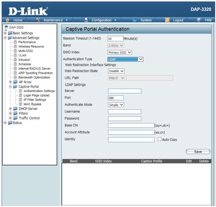
LDAP
After selecting LDAP as the Authentication Type, administrators can configure the LDAP authentication settings required to join the network.
Session Enter the session timeout value here. This value can be from 1 to 1440
timeout minutes. By default, this value is 60 minutes.
(1-1440):
Band: Select 2.4 Ghz.
SSID Index: Select the SSID for this Authentication.
Authentication Type: Select the captive portal encryption type here. Options to choose from are Web Redirect,Username/Password,Passcode,Remote RADIUS,LDAP and POP3.
Web Default is Disable or select Enable to enable the website redirection feature.
Redirection
State:
URL Path: Select whether to use either HTTP or HTTPS here. After selecting either http://or https://, enter the URL of the website that will be used in the space provided.
Server: Enter the LDAP server's IP address or domain name here.
Port: Enter the LDAP server's port number here.
Authentication Mode: Select the authentication mode here. Options to choose from are Simple and TLS.
Username: Enter the LDAP server account's username here.
Password: Enter the LDAP server account's password here.

Base DN: Enter the administrator's domain name here
Account Enter the LDAP account attribute string here.
Attribute:
Identity: This string will be used to search for clients.
Enter the identity's full path string here. Alternatively, select the Auto Copy checkbox to automatically add the generic full path of the web page in the identity field.
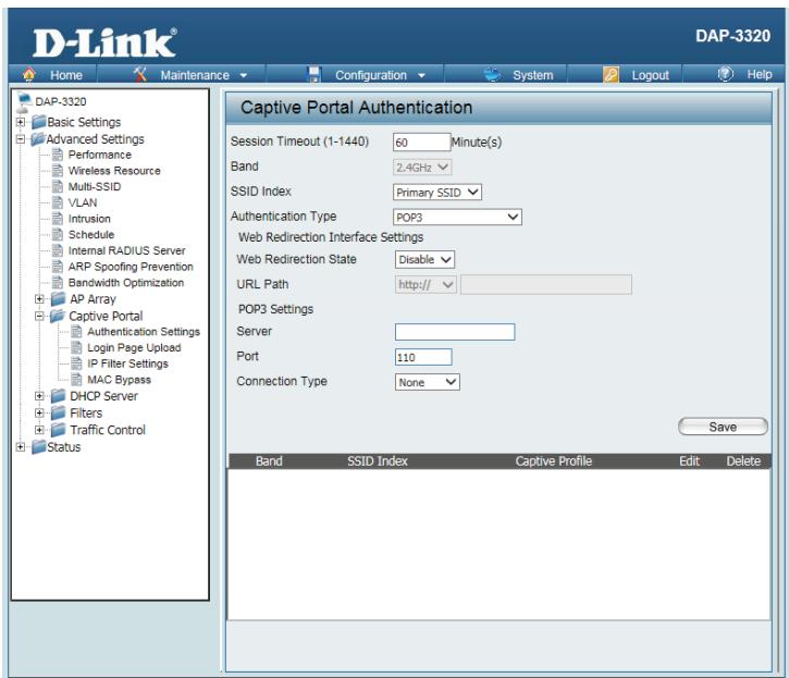
POP3
After selecting POP3 as the Authentication Type, administrators can configure the POP3 authentication settings required to join the network.
Session Enter the session timeout value here. This value can be from 1 to 1440
timeout minutes. By default, this value is 60 minutes.
(1-1440):
Band: Select 2.4 Ghz.
SSID Index: Select the SSID for this Authentication.
Authentication Select the captive portal encryption type here. Options to choose from are
Type: Web Redirect,Username/Password,Passcode,Remote RADIUS,LDAP and POP3.
Web Default is Disable or select Enable to enable the website redirection feature.
Redirection
State:
URL Path: Select whether to use either HTTP or HTTPS here. After selecting either http://or https://, enter the URL of the website that will be used in the space provided.
Server: Enter the POP3 server's IP address or domain name here.
Port: Port: Enter the POP server's port number here.
Connection Select the connection type here; either None or SSL/TLS.
Type:
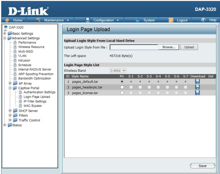
Login Page Upload
In this window, users can upload a custom login page picture that will be used by the captive portal feature. Click the Browse button to navigate to the image file, located on the managing computer and then click the Upload button to initiate the upload.
Upload In this field the path to the image file, that will be uploaded, will be displayed.
picture Alternatively, the path can be manually entered here.
from file:
Login Page Select the wireless band and login style that will be used for each SSID.
Style List: Click the Download button to download the login page template file and Click the Del button to delete the template file.
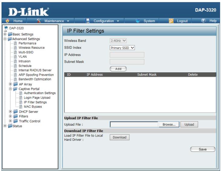
IP Filter Settings
Enter the IP address or network address that will be used in the IP filter rule. For example, an IP address like 192.168.70.66 or a network address like 192.168.70.0. This IP address or network will be inaccessible to wireless clients on this network.
Wireless Select the wireless band for MAC Bypass.
Band:
IP Address: Enter the IP address or network address.
Subnet Enter the subnet mask of the IP address or networks address.
Mask:
Upload IP To upload an IP filter list file, click Browse and navigate to the IP filter list
Filter File: file saved on your computer, and then click Upload.
Download To download IP Filter list file, click Download and to save the IP Filter list.
IP Filter File:
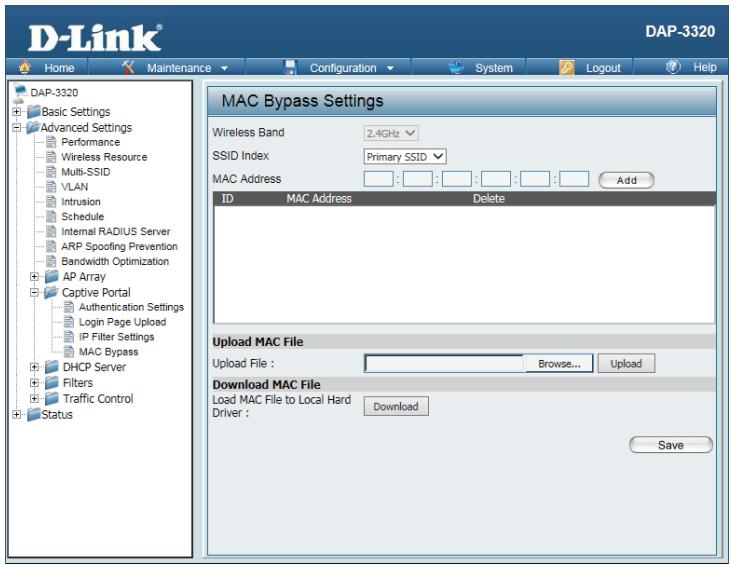
MAC Bypass
The DAP-3320 features a wireless MAC Bypass. Once a MAC address is added to the bypass list, that client will skip the Captive Portal Authentication process when joining a network. Once an administrator is finished adjusting these settings, click the Save button to have the changes take effect.
Wireless Select the wireless band for MAC Bypass.
Band:
SSID Index: Select the SSID for MAC Bypass.
MAC Enter each MAC address that you wish to include in your bypass list and then Address: click Add.
MAC When a MAC address is entered, it appears in this list. Highlight a MAC address and click the Delete icon to remove it from this list.
List:
Upload File: To upload a MAC bypass list file, click Browse and navigate to the MAC bypass list file saved on the managing computer, and then click Upload.
Load MAC Click Download to save the MAC bypass list file.
File to Local
Hard Drive:
DHCP Server
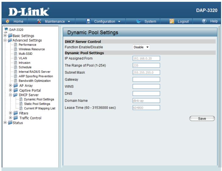
Dynamic Pool Settings
The DHCP address pool defines the range of the IP addresses that can be assigned to stations in the network. A Dynamic Pool allows wireless stations to receive an available IP with lease time control. If needed or required in the network, the DAP-3320 is capable of acting as a DHCP server.
Function Dynamic Host Configuration Protocol (DHCP) assigns dynamic IP addresses Enable/ to devices on the network. This protocol simplifies network management and
Disable: allows new wireless devices to receive IP addresses automatically without the need to manually assign new IP addresses. Select Enable to allow the DAP-3320 to function as a DHCP server.
IP Assigned Input the first IP address available for assignment on your network.
From:
IP Pool Enter the number of IP addresses available for assignment. IP addresses are Range (1-254): increments of the IP address specified in the "IP Assigned From" field.
Subnet All devices in the network must have the same subnet mask to communicate.
Mask: Enter the submask for the network here.
Gateway: Enter the IP address of the gateway on the network.
WINS: Specify the Windows Internet Naming Service (WINS) server address for the wireless network. WINS is a system that determines the IP address of a network computer that has a dynamically assigned IP address.
DNS: Enter the IP address of the Domain Name System (DNS) server. The DNS server translates domain names such as www.dlink.com into IP addresses.
Domain Enter the domain name of the network, if applicable. (An example of a
Name: domain name is: www.dlink.com.)
Lease Time: The lease time is the period of time before the DHCP server will assign new IP addresses. (60-31536000 sec)
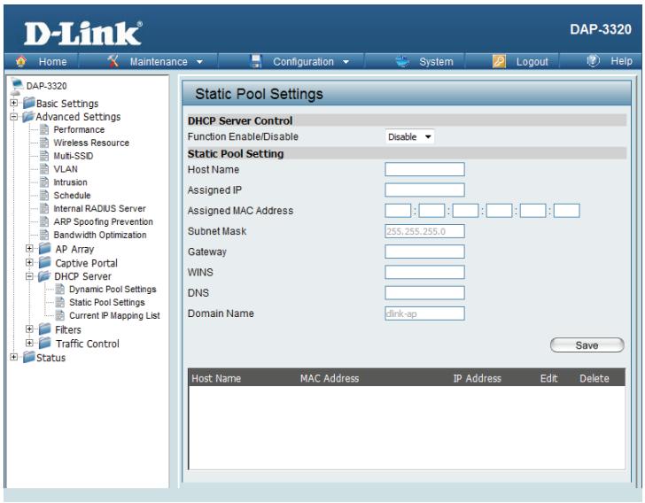
Static Pool Setting
A static pool allows specific IP addresses to be reserved to wireless stations.
Function Dynamic Host Configuration Protocol (DHCP) assigns IP addresses to wireless Enable/ devices on the network. This protocol simplifies network management and
- Disable: allows new wireless devices to receive IP addresses automatically without the need to manually assign IP addresses. Select Enable to allow the DAP-3320 to function as a DHCP server.
Assigned IP: Use the Static Pool Settings to reserve IP addresses to specific devices. The IP addresses assigned in the Static Pool list must NOT be in the same IP range as the Dynamic Pool. After you have assigned a static IP address to a device via its MAC address, click Save; the device will appear in the Assigned Static Pool at the bottom of the screen. You can edit or delete the device in this list.
Assigned Enter the MAC address of the device requesting association here. MAC Address:
Subnet Mask: Define the submask of the IP address specified in the IP Assigned From field.
Gateway: Specify the Gateway address for the wireless network.
WINS: Specify the Windows Internet Naming Service (WINS) server address for the wireless network. WINS is a system that determines the IP address of a network computer with a dynamically assigned IP address, if applicable.
DNS: Enter the Domain Name System (DNS) server address for the wireless network. The DNS server translates domain names such as www.dlink.com into IP addresses.
Domain Specify the domain name for the network.
Name:
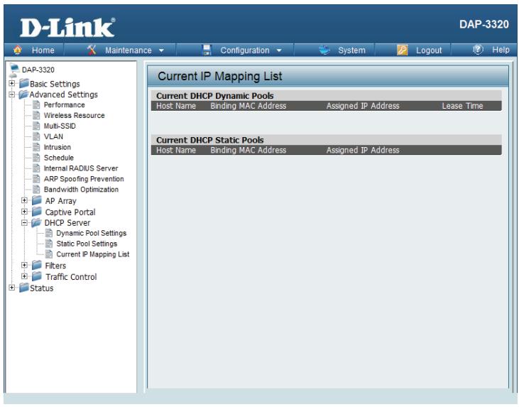
Current IP Mapping List
This window displays information about the current assigned DHCP dynamic and static IP address pools. This information is available when you enable DHCP server on the AP and assign dynamic and static IP address pools.
| Current DHCP Dynamic Profile: | These are IP address pools the DHCP server has assigned using the dynamic pool setting. |
| Host Name: | The host name of a device on the network that is assigned an IP address from the DHCP dynamic pool. |
| Binding MAC Address: | The MAC address of a device on the network that is assigned an IP address from the DHCP dynamic pool. |
| Assigned IP Address: | The current corresponding DHCP-assigned IP address of the device. |
| Lease Time: | The length of time that the dynamic IP address will be valid. |
| Current DHCP Static Pools: | These are the IP address pools of the DHCP server assigned through the static pool settings. |
| Host Name: | The host name of a device on the network that is assigned an IP address from the DHCP dynamic pool. |
| Binding MAC Address: | The MAC address of a device on the network that is within the DHCP static IP address pool. |
| Assigned IP Address: | The current corresponding DHCP-assigned static IP address of the device. |
Filters
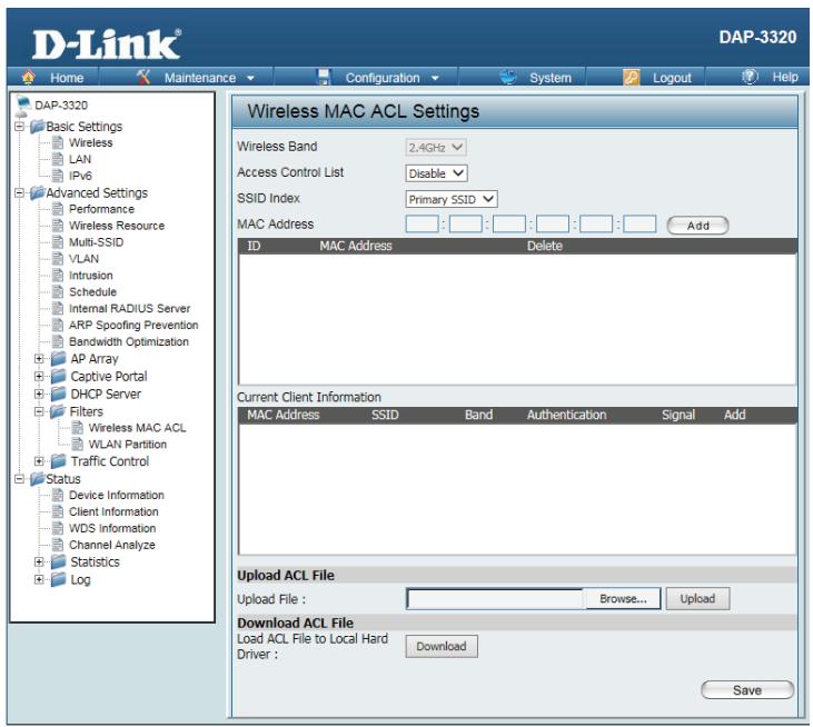
Wireless MAC ACL
Wireless Displays the current wireless band rate.
Band:
Access Select Disable to disable the filters function. Control List:
MAC Select Accept to accept only those devices with MAC addresses in the Access Address: Control List. All other devices not on the list will be rejected.
MAC Select Reject to reject the devices with MAC addresses on the Access Control Address List. All other devices not on the list will be accepted. List:
Upload ACL Enter each MAC address that you wish to include in your filter list, and click File: Add.
When you enter a MAC address, it appears in this list. Highlight a MAC address and click Delete to remove it from this list.
You may create an ACL list and upload it to the access point instead of manually entering the information. Once created, click the Browse button and locate your file. Select it and then click Upload.
Download Click Download to export the ACL to a file on your computer.
ACL File:
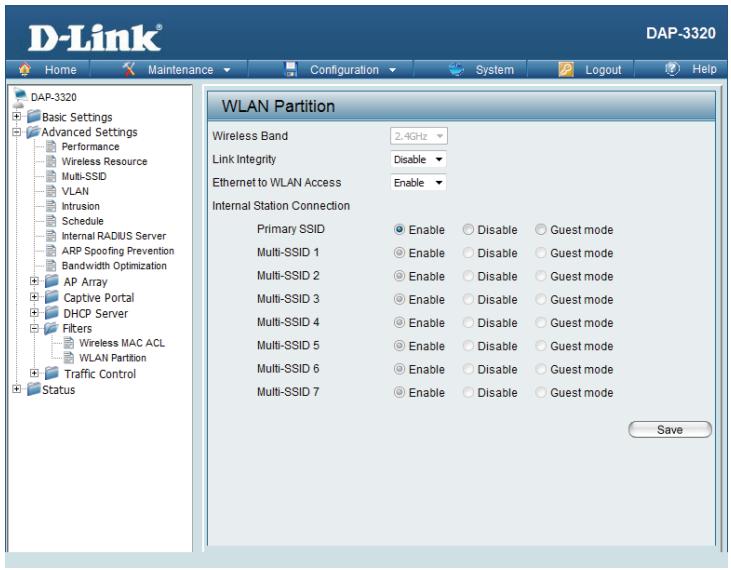
WLAN Partition
Wireless Displays the current wireless band rate.
Band:
Link Select Enable or Disable.
Integrity:
Ethernet The default is Enable. When disabled, all data from the Ethernet port to to WLAN associated wireless devices will be blocked. Wireless devices can still send
Access: data to the Ethernet port.
Internal The default value is Enable, which allows stations to inter-communicate by Station connecting to a target AP. When disabled, wireless stations cannot exchange Connection: data through the AP.
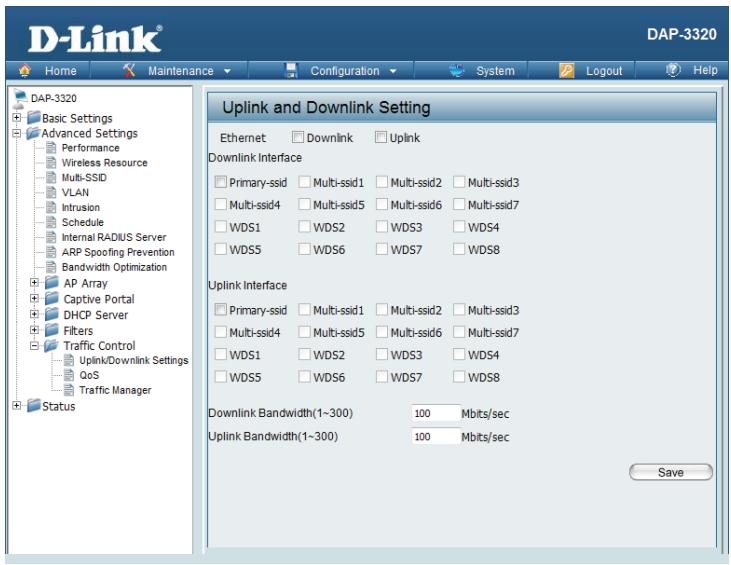
Traffic Control Uplink/Downlink Settings
The uplink/downlink setting allows users to customize the downlink and uplink interfaces including specifying downlink/uplink bandwidth rates in Mbits per second. These values are also used in the QoS and Traffic Manager windows. Once the desired uplink and downlink settings have been selected, click the Save button to let your changes take effect.
Downlink The downlink bandwidth in Mbits per second.
Bandwidth:
Uplink The uplink bandwidth in Mbits per second. Bandwidth:
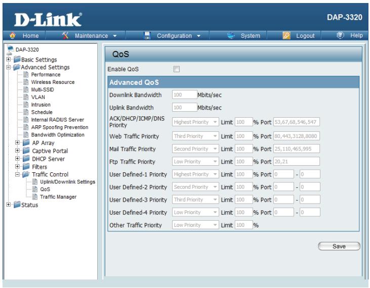
QoS
Quality of Service (QoS) enhances the experience of using a network by prioritizing the traffic of different applications. A QoS Rule identifies a specific message flow and assigns a priority to that flow. For most applications, the priority classifiers ensure the right priorities and specific QoS Rules are not required. QoS supports overlaps between rules. If more than one rule matches a specific message flow, the rule with the highest priority will be used.
QoS Enable this option if you want to allow QoS to prioritize your traffic Priority (Quality of Classifiers.
Service):
HTTP: Allows the access point to recognize HTTP transfers for many common audio and video streams and prioritize them above other traffic. Such streams are frequently used by digital media players.
Automatic: When enabled, this option causes the access point to automatically attempt to prioritize traffic streams that it does not otherwise recognize, based on the behavior that the streams exhibit. This acts to de-prioritize streams that exhibit bulk transfer characteristics, such as file transfers, while leaving interactive traffic, such as gaming or VoIP, running at a normal priority.
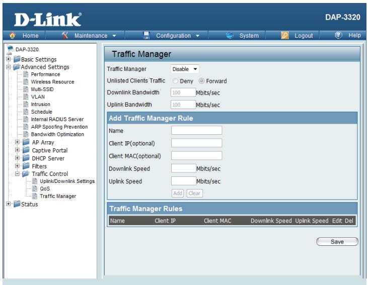
Traffic Manager
The traffic manager feature allows users to create traffic management rules that specify how to deal with listed client traffic and specify downlink/uplink speed for new traffic manager rules. Click the Save button to let your changes take effect.
Traffic Use the drop-down menu to Enable the traffic manager feature. Manager:
Unlisted Select Deny or Forward to determine how to deal with unlisted client traffic.
Client
Traffic:
Downlink The downlink bandwidth in Mbits per second. This value is entered in the Bandwidth: Uplink/Downlink Setting window.
Uplink The uplink bandwidth in Mbits per second. This value is entered in the Uplink/ Bandwidth: Downlink Setting window.
Status
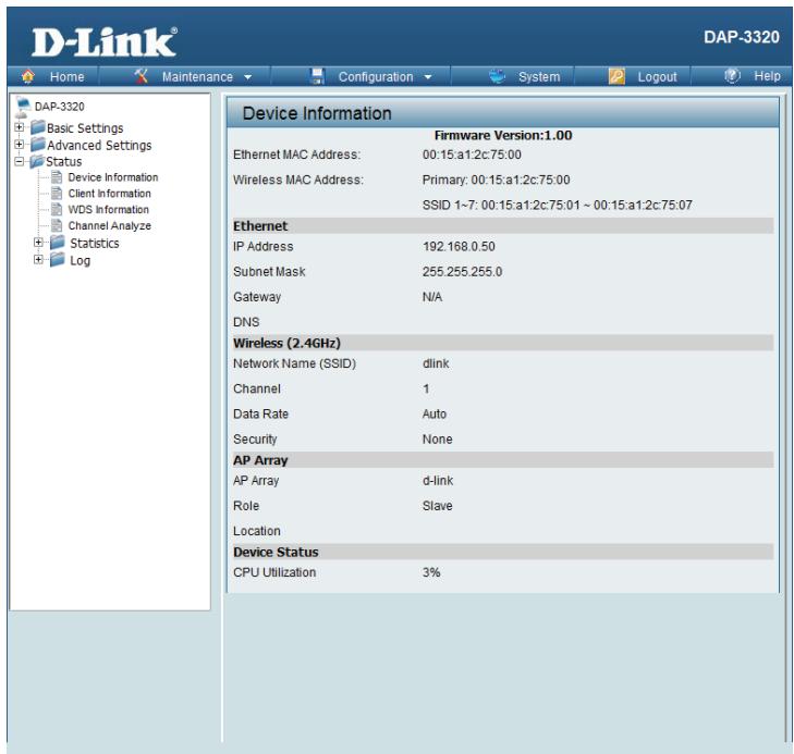
Device Information
This read-only window displays the configuration settings of the DAP-3320, including the firmware version and the device's MAC address.
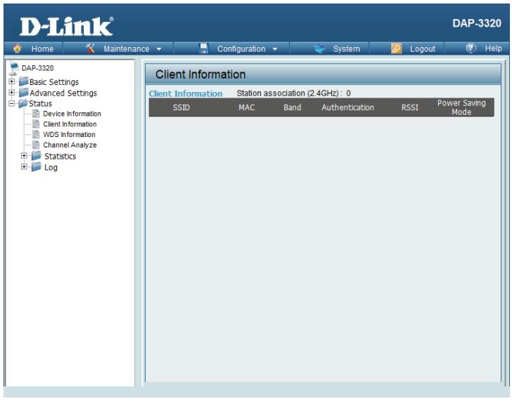
Client Information
This window displays the wireless client information for clients currently connected to the DAP-3320. The following information is available for each client communicating with the DAP-3320.
SSID: Displays the SSID of the client.
MAC: Displays the MAC address of the client.
Band: Displays the wireless band that the client is connected to.
Authentication: Displays the type of authentication being used.
Signal: Displays the client's signal strength.
Power Displays the status of the power saving feature.
Saving
Mode:
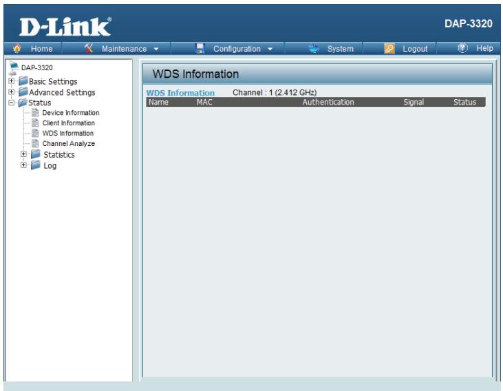
WDS Information
This window displays the Wireless Distribution System information for clients currently connected to the DAP-3320. The following information is available for each client communicating with the DAP-3320.
Name: Displays the SSID of the client.
MAC: Displays the MAC address of the client.
Authentication: Displays the type of authentication being used.
Signal: Displays the client's signal strength.
Status: Displays the status of the power saving feature.
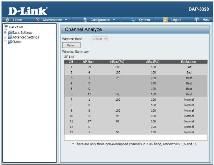
Channel Analyze
Wireless 2.4 Ghz
Band:
Detect: Click the Detect button to scan.
AP List: This will list the transmitting channels and quality.
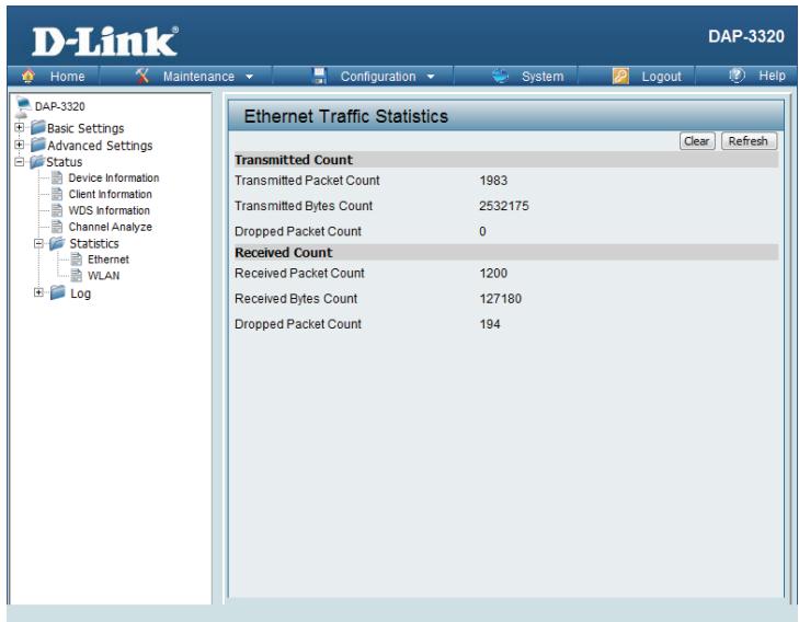
Statistics Ethernet
This page displays transmitted and received count statistics for packets and bytes.
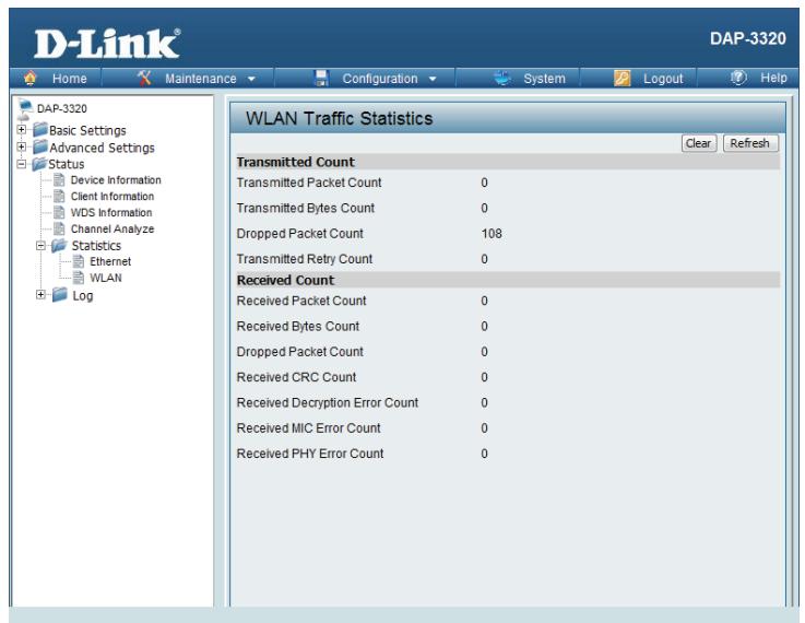
WLAN Traffic
This page displays wireless network statistics for data throughput, transmitted and received frames, and frame errors.
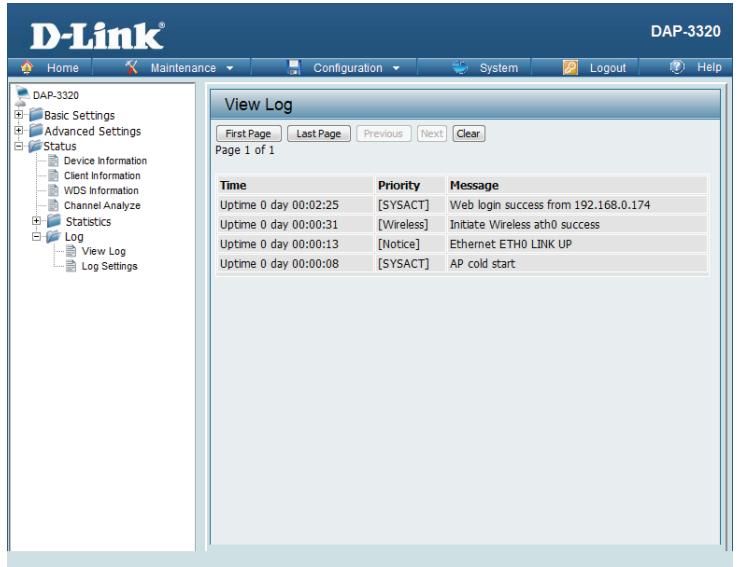
Log View Log
The AP's embedded memory displays system and network messages including a time stamp and message type. The log information includes but is not limited to the following items: cold start AP, upgrading firmware, client associate and disassociate with AP, and web login. The web page holds up to 500 logs.
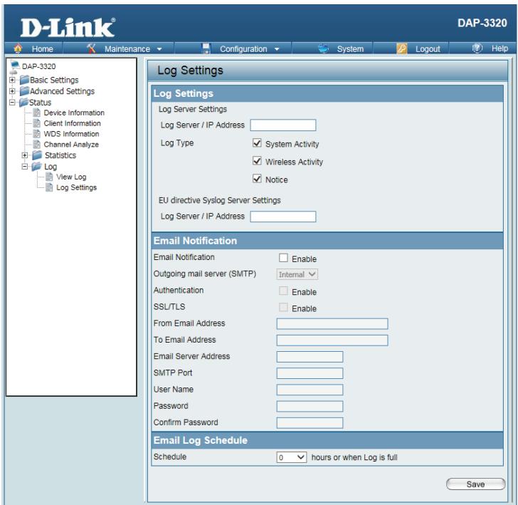
Log Settings
Log Server/ Enter the IP address of the server you would like to send the DAP-3320 log to.
IP Address:
Log Type: Check the box for the type of activity you want to log. There are three types:
System Activity, Wireless Activity, and Notice.
EU directive Enter the EU Directive Log Server IP Address.
Syslog Server
Settings:
Email Check to enable Email notification.
Notification:
Outgoing Mail Select the SMTP server from the drop-down menu.
Server (SMTP):
Authentication: Check to enable authentication.
SSL /TLS: Check to enable SSL/TLS authentication.
From Email Enter the "From" email address.
Address:
To Email Address: Enter the destination email address.
Email Server Enter the Email Server Address.
Address:
SMTP Port: Enter the SMTP port.
Username: Enter your email username.

Password: Enter your email password.
Confirm Enter your email password again. Password:
Schedule: Select when to send the log to your email (in hours). You will receive an email when the log is full too.
Maintenance
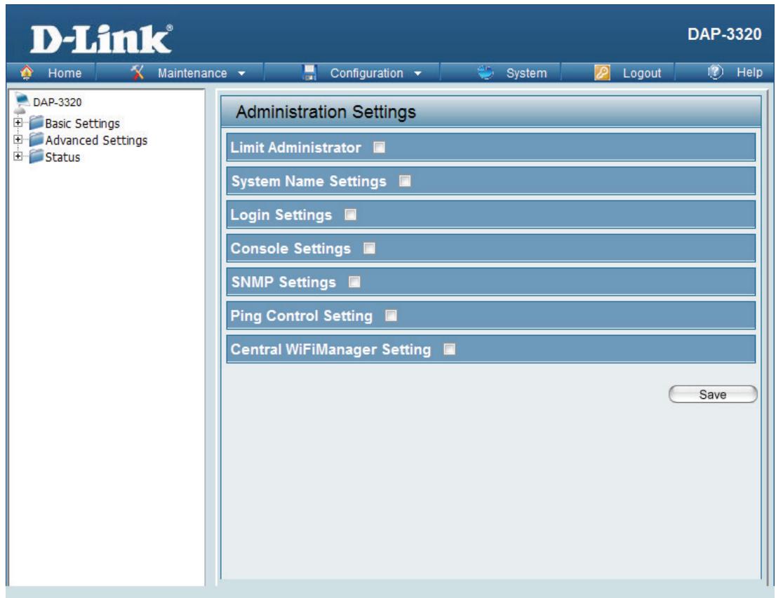
Administration Settings
Check one or more of the five main categories to view the various hidden administrator parameters and settings displayed on the next five pages.
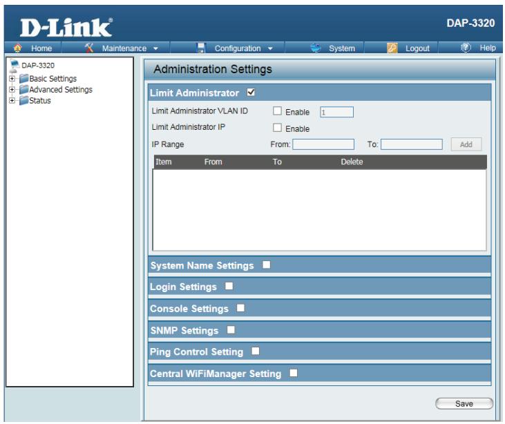
Limit Administrator
Each of the five main categories display various hidden administrator parameters and settings.
Limit Check the box provided and the enter the specific VLAN ID that the Administrator administrator will be allowed to log in from.
VLAN ID:
Limit Check to enable the Limit Administrator IP address. Administrator
IP:
IP Range: Enter the IP address range that the administrator will be allowed to log in from and then click the Add button.
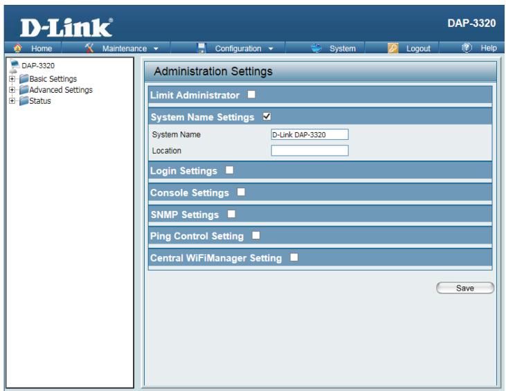
System Name Settings
Each of the five main categories display various hidden administrator parameters and settings.
System The name of the device. The default name is D-Link DAP-3320.
Name:
Location The physical location of the device, e.g. 72nd Floor, D-Link HQ.
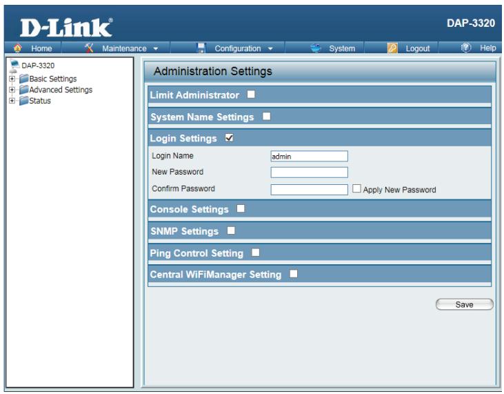
Login Settings
Each of the five main categories display various hidden administrator parameters and settings.
Login Enter a user name. The default is admin.
Name:
Old When changing your password, enter the old password here.
Password:
New When changing your password, enter the new password here. The password
Password: is case-sensitive. "A" is a different character than "a." The length should be between 0 and 12 characters.
Confirm Enter the new password a second time for confirmation purposes.
Password:
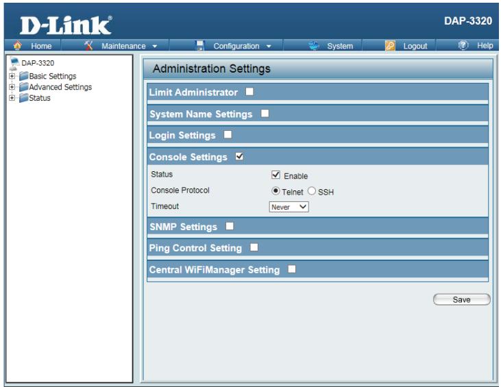
Console Settings
Each of the five main categories display various hidden administrator parameters and settings.
Status: Status is enabled by default. Uncheck the box to disable the console.
Console Select the type of protocol you would like to use, Telnet or SSH. Protocol:
Timeout: Set to 1 Min, 3 Mins, 5 Mins, 10 Mins, 15 Mins or Never.
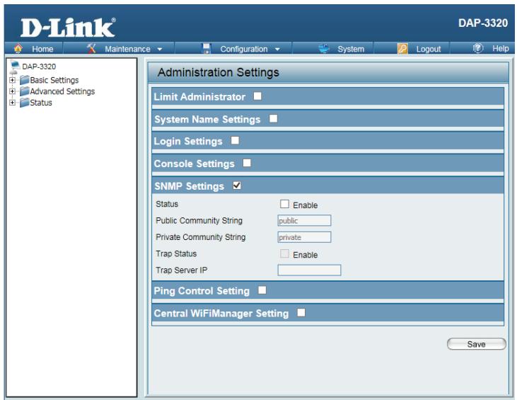
SNMP Settings
Each of the five main categories display various hidden administrator parameters and settings.
Status: Check the box to enable the SNMP functions. This option is disabled by default.
Public Enter the public SNMP community string. Community String: Private Enter the private SNMP community string. Community String:
Trap Status: Check the box to enable Trap Status.
Trap Server IP: Enter the Trap Server IP address.
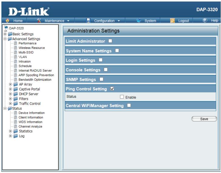
Ping Control
Status: Check the box to enable Ping control. Ping works by sending ICMP "echo request" packets to the target host and listening for ICMP echo response replies. The default is enabled. If not enabled, the access point will not reply to pings.
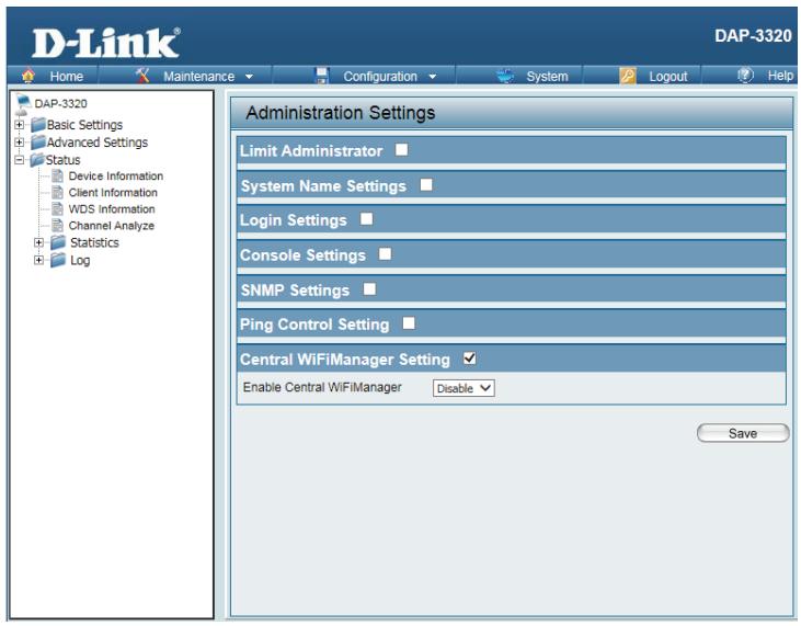
Central WiFiManager Settings
The Central WiFiManager section is used to configure and manage a set of APs on a network into a single group in order to simplify management. Central WiFiManager and AP Array may not be used simultaneously.
Enable Central Select to enable or disable the Central WiFiManager.
WiFiManager:
Firmware and SSL Certification Upload
This page allows the user to perform a firmware upgrade. Be sure to check the support.dlink.com website periodically for the latest firmware updates to keep your product up to date with the latest features.
Upload The current firmware version is displayed above the file location field. Firmware After downloading the most recent version of the firmware for the From Local DAP-3320 from http://support.dlink.com to your local computer, use the Hard Drive: Browse button to locate the firmware file on your computer. Click Upload to update the firmware version. Please don't turn the power off while upgrading.
Language You may load a language pack to display the utility in another language. Pack Click Browse to locate the language pack file on your local computer. Upgrade: After selecting and opening the file, click Upload to upload the file to the DAP-3320.
Upload SSL Click Browse to locate the SSL Certification file on your local computer. Certification After selecting and opening the file, click Upload to upload the file to the From Local DAP-3320. Hard Drive:

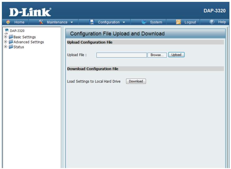
Configuration File Upload
Upload File: Click the Browse button to locate a previously saved configuration file on your local computer. After selecting the file, click Upload to apply the configuration settings to the DAP-3320.
Download Click Download to save the current DAP-3320 configuration to your local Configuration computer.
File:
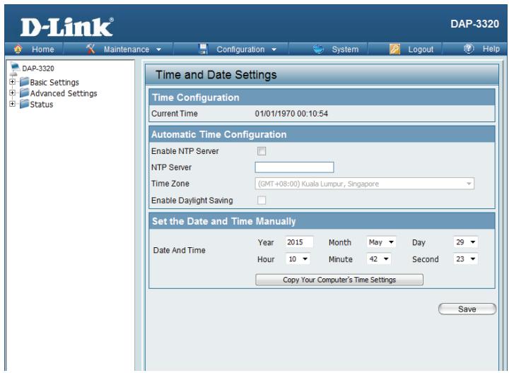
Time and Date
Current Displays the current time and date settings.
Time:
Enable NTP Check to enable the AP to get system time from an NTP server.
Server:
NTP Server: Enter the NTP server URL or IP address.
Time Zone: Use the drop-down menu to select your correct Time Zone.
Enable Check the box to Enable Daylight Saving Time.
Daylight
Saving:
Daylight Use the drop-down menu to select the correct Daylight Saving offset.
Saving
Dates:
Set the Date You can either manually set the time for your AP here, or you can click the
and Time Copy Your Computer's Time Settings button to copy the time from the
Manually: computer you are using (Make sure that the computer's time is set correctly).
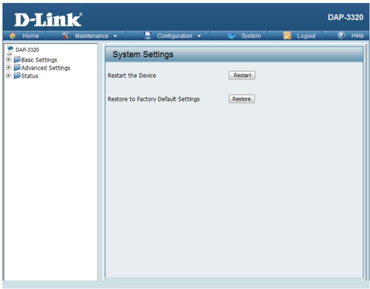
System System Settings
Restart the Click Restart to restart the DAP-3320.
Device:
Restore Click Restore to restore the DAP-3320 back to factory default settings.
to Factory
Default
Settings:
Help
Help: Scroll down the Help page for topics and explanations.
Basic Settings
Change the wireless settings on the device for an existing network or create a new network.
Wireless Band
This is the operating frequency band. This Access Point (AP), operates 2.4GHz. 2.4GHz works best with legacy devices and suitable for longer ranges.
Mode
Select between Access Point, Wireless Distribution System (WDS) with AP, WDS and Wireless Client mode.
Network Name/Service Set Identifier (SSID)
The SSID factory default is "dlink". Change the SSID to connect to existing wireless networks or establish a new wireless network.
SSID Visibility
The SSID Visibility signal is enabled by default. Select Disable to make the Access Point invisible to all client devices.
Auto Channel Selection
Enabled by default, when the device boots up, to automatically search for the best available channel.
Channel
Auto Channel Selection is set as default. Settings for the channel can be configured to work with existing wireless networks or customized a new wireless network.
Channel Width
Setup the Channel bandwidths. Use 20MHz and Auto 20/40MHz for 802.11n and non-802.11n wireless devices. Connect Mixed 802.11b/g/n for 2.4GHz. When using Auto 20/40MHz channel settings data can be transmitted using 40MHz.
Captive Profile
This is the front-end authentication method for the Primary SSID. Bind a captive portal policy profile to the Primary SSID after being defined in the Captive Portal Settings page.
Authentication
Open System is the default authentication mode. Choose Data Encryption Mode to enable encryption.
Open System
All devices are allowed to access the Access Point.
Shared Key
Users must use the same WEP Share Key to access the Access Point on this network.
WPA-Personal/WPA2-Personal/WPA-Auto-Personal
Wi-Fi Protected Access (WPA) uses AES/TKIP encryption to protect the network. WPA and WPA2 Personal uses different algorithms. WPA Auto-Personal uses both WPA and WPA2 authentication.
Periodical Key Change
Periodical Key Change generates a random WPA key from the time the device is activated. An email is sent bearing the current key and Periodical Key Change information to the administrator.
WPA-Enterprise/WPA2-Enterprise/WPA-Auto-Enterprise
Wi-Fi Protected Access authorizes and authenticates users onto the wireless network. WPA uses stronger security than WEP and is based on a combination of authentication mechanisms, Wi-Fi access policies, and authentication protocols. Encryption relies on a RADIUS server for authentication but doesn't require an Accounting, Backup, or Backup Accounting server.
802.1x
802.1x is an access control system used on Ethernet and wireless networks. A key is automatically generated from a server or switch. In order to use 801.1x, implement PAE and restart the Access Point. The AP then authenticates either to a RADIUS server, local server or switch. Select one of the options from the encryption menu to create an authentication sequence and key generation.
Network Access Protection
Network Access Protection (NAP) is a feature of Windows Server 2008. NAP controls access to network resources based on a client computer's identity and compliance with corporate governance policy. NAP allows network administrators to define granular levels of network access based on the client, the groups, or which the client belongs, and the degree to which that client is compliant with corporate policies. The NAP provides a mechanism to automatically bring the client back into compliance and then dynamically increase its level of network access.
LAN Settings
The default IP address is 192.168.0.50 and the subnet mask is 255.255.255.0. Alternatively use the given parameters provided to configure the LAN settings.
Get IP From
Static IP is default. Set the IP address manually. Enable Dynamic IP (DHCP) for the host to automatically assign IP addresses.
IP Address
The default IP address is 192.168.0.50. Configure the wireless clients accessing the AP to be within the same IP address and subnet mask range. The IP address range can be from 1-254.
Subnet Mask
Subnet mask determines what subnet an IP address belongs to. The default subnet is 255.255.255.0.
Default Gateway
The Default Gateway is the external IP address networks use. This is either provided by your ISP or network administrator.
DNS
Domain Name System turns domain names, like dlink.com into an IP address that computers use to identify each other on the network.
IPv6 LAN Settings
IPv6 is the upgrade to IPv4. It specifies the formats of packets and the addressing scheme across multiple networks.
Get IP From
IPv6 default setting is Auto. Select Static to manually configure IP addresses.
Wireless Security
This section will show you the different levels of security you can use to protect your data from intruders. The DAP-3320 offers the following types of security:
- WEP (Wired Equivalent Privacy)
WPA-Personal (Wi-Fi Protected Access)
WPA-Enterprise (Wi-Fi Protected Access)
What is WEP?
WEP, or Wired Equivalent Privacy, is a Wi-Fi security protocol that encrypts transmitted data. WEP is an older protocol that is not believed to be as effective anymore.
WEP uses a passphrase or key to authenticate your wireless connection. For 64-Bit WEP, the key is an alpha-numeric password that is 10 hex digits or an ASCII password consisting of 5 text characters. The hex digits are either numbers from 0 to 9 or letters from A to F. For 128-Bit WEP, the key is an alpha-numeric password that is 26 hex digits or an ASCII password with 13 text characters.
Configure WEP
It is recommended to enable encryption on your wireless access point before your wireless network adapters. Please establish wireless connectivity before enabling encryption. Your wireless signal may degrade when enabling encryption due to the added overhead.
- Log into the web-based configuration by opening a web browser and entering the IP address of the access point (dlinkap. local). Click on Setup and then click Wireless Setup on the left side.
- Next to Security Mode, select WEP. Note: Choosing WEP means the device will only operate in Legacy wireless mode (802.11B/G) and will not provide 802.11N performance.
- Next to WEP Encryption, select 64 Bit(10 hex digits), 64 Bit(5 ASCII characters), 128 Bit(26 hex digits) or 128 Bit(13 ASCII characters).
- Next to WEP Key 1, enter a set of digits or letters from A to F, or a string of text.
- Next to Authentication, select Both or Shared Key.
- Click Save Settings at the top of the window to save your settings. If you are configuring the access point with a wireless adapter, you will lose connectivity until you enable WPA-PSK on your adapter and enter the same passphrase as you did on the access point.
What is WPA?
WPA, or Wi-Fi Protected Access, is a Wi-Fi standard that was designed to improve the security features of WEP (Wired Equivalent Privacy).
The 2 major improvements over WEP:
- Improved data encryption through the Temporal Key Integrity Protocol (TKIP). TKIP scrambles the keys using a hashing algorithm and, by adding an integrity-checking feature, ensures that the keys haven't been tampered with. WPA2 is based on 802.11i and uses Advanced Encryption Standard (AES) instead of TKIP.
- User authentication, which is generally missing in WEP, through the extensible authentication protocol (EAP). WEP regulates access to a wireless network based on a computer's hardware-specific MAC address, which is relatively simple to be sniffed out and stolen. EAP is built on a more secure public-key encryption system to ensure that only authorized network users can access the network.
WPA-PSK/WPA2-PSK uses a passphrase or key to authenticate your wireless connection. The key is an alpha-numeric password between 8 and 63 characters long. The password can include symbols (!?*_) and spaces. This key must be the exact same key entered on your wireless bridge or access point.
WPA/WPA2 incorporates user authentication through the Extensible Authentication Protocol (EAP). EAP is built on a more secure public key encryption system to ensure that only authorized network users can access the network.
Configure WPA/WPA2 Personal
It is recommended to enable encryption on your wireless access point before your wireless network adapters. Please establish wireless connectivity before enabling encryption. Your wireless signal may degrade when enabling encryption due to the added overhead.
- Log into the web-based configuration by opening a web browser and entering the IP address of the access point (dlinkap. local). Click on Setup and then click Wireless Setup on the left side.
- Next to Security Mode, select WPA-Personal.
- Next to WPA Mode, select Auto(WPA or WPA2), WPA2 only, or WPA only.
- Next to Cipher Type, select TKIP, AES, or TKIP and AES.
- Next to Pre-Shared Key, enter a key. The key is entered as a passphrase in ASCII format at both ends of the wireless connection. The passphrase must be between 8-63 characters.
- Click Save Settings at the top of the window to save your settings. If you are configuring the access point with a wireless adapter, you will lose connectivity until you enable WPA-PSK on your adapter and enter the same passphrase as you did on the access point.
Configure WPA/WPA2 Enterprise
It is recommended to enable encryption on your wireless access point before your wireless network adapters. Please establish wireless connectivity before enabling encryption. Your wireless signal may degrade when enabling encryption due to the added overhead.
- Log into the web-based configuration by opening a web browser and entering the IP address of the access point (dlinkap. local). Click on Setup and then click Wireless Setup on the left side.
- Next to Security Mode, select WPA-Enterprise.
- Next to WPA Mode, select Auto(WPA or WPA2), WPA2 only, or WPA only.
- Next to Cipher Mode, select TKIP, AES, or Auto.
- Next to RADIUS Server IP Address, enter the IP Address of your RADIUS server.
- Next to RADIUS Server Port, enter the port you are using with your RADIUS server. 1812 is the default port.
- Next to RADIUS Server Shared Secret, enter the security key.
- Click Advanced to enter settings for a secondary RADIUS Server.
- Click Save Settings to save your settings.
Connect to a Wireless Network Using Windows XP
Windows® XP users may use the built-in wireless utility (Zero Configuration Utility). The following instructions are for Service Pack 2 users. If you are using another company's utility or Windows® 2000, please refer to the user manual of your wireless adapter for help with connecting to a wireless network. Most utilities will have a "site survey" option similar to the Windows®
XP utility as seen below.
If you receive the Wireless Networks Detected bubble, click on the center of the bubble to access the utility.
or
Right-click on the wireless computer icon in your system tray (lower-right corner next to the time). Select View Available Wireless Networks.
The utility will display any available wireless networks in your area. Click on a network (displayed using the SSID) and click the Connect button.
If you get a good signal, but cannot access the Internet, check you TCP/IP settings for your wireless adapter. Refer to the Networking Basics section in this manual for more information.
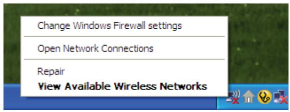
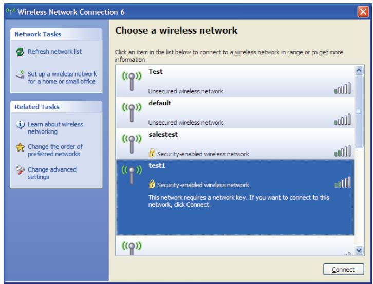
Configure WPA-PSK
It is recommended to enable WEP on your wireless bridge or access point before configuring your wireless adapter. If you are joining an existing network, you will need to know the WEP key being used.
- Open the Windows XP Wireless Utility by right-clicking on the wireless computer icon in your system tray (lower-right corner of screen). Select View Available Wireless Networks.
- Highlight the wireless network (SSID) you would like to connect to and click Connect.
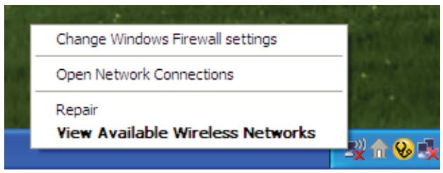

- The Wireless Network Connection box will appear. Enter the WPA-PSK passphrase and click Connect.
It may take 20-30 seconds to connect to the wireless network. If the connection fails, please verify that the WPA-PSK settings are correct. The WPA-PSK passphrase must be exactly the same as on the wireless access point.
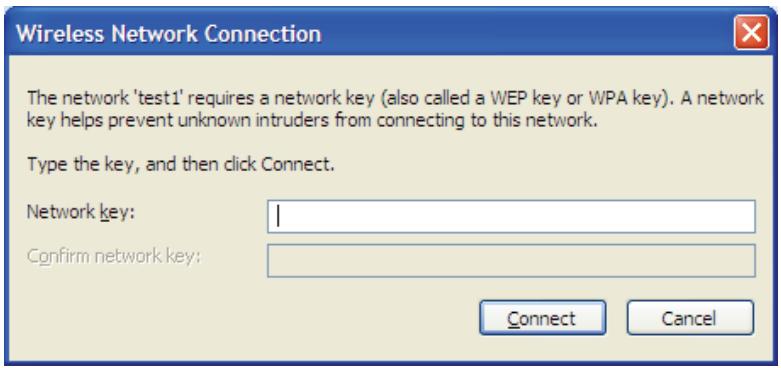
Using Windows Vista
Windows Vista® users may use the convenient, built-in wireless utility. Follow these instructions:
From the Start menu, go to Control Panel, and then click on Network and Sharing Center.
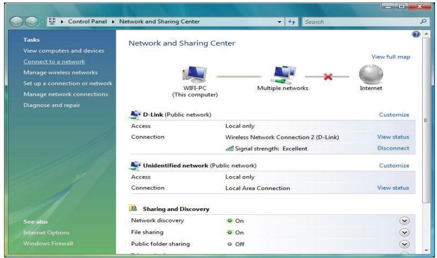
The utility will display any available wireless networks in your area. Click on a network (displayed using the SSID) under Select a network to connect to and then click the Connect button.
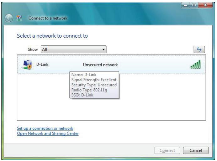
Click Connect Anyway to continue.
The utility will display the following window to indicate a connection is being made.
The final window indicates the establishment of a successful connection.
The next two pages display the windows used to connect to either a WEP or a WPA-PSK wireless network.
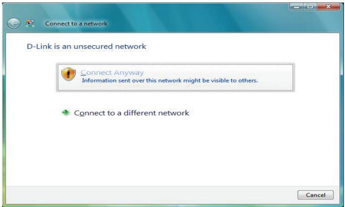
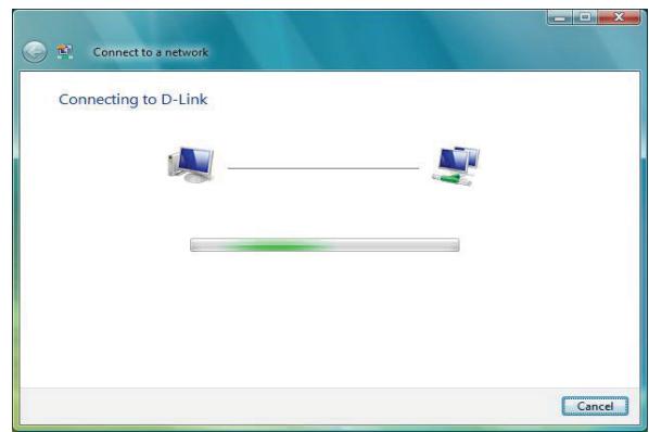
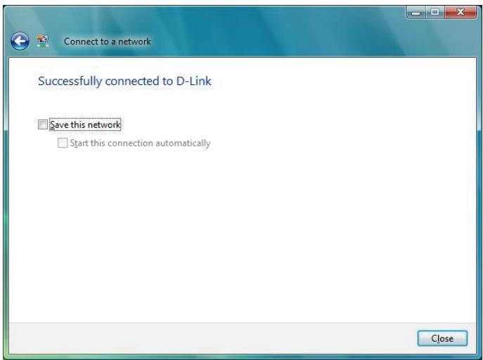
Configure WPA-PSK
It is recommended to enable WEP on your wireless bridge or access point before configuring your wireless adapter. If you are joining an existing network, you will need to know the WEP key being used.
Click on a network (displayed using the SSID) using WPA-PSK under Select a network to connect to and then click the Connect button.
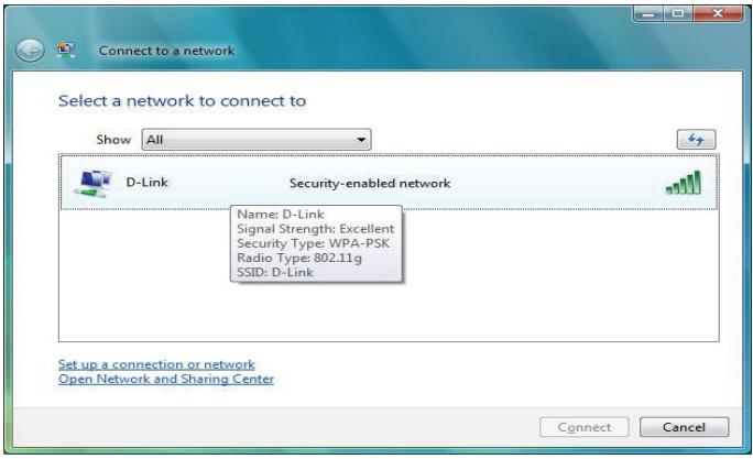
Enter the appropriate security key or passphrase in the field provided and then click the Connect button.
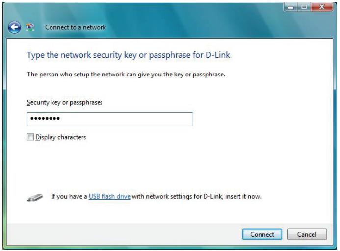
Using Windows® 7
It is recommended to enable wireless security (WPA/WPA2) on your wireless router or access point before configuring your wireless adapter. If you are joining an existing network, you will need to know the security key or passphrase being used.
- Click on the wireless icon in your system tray (lower-right corner).
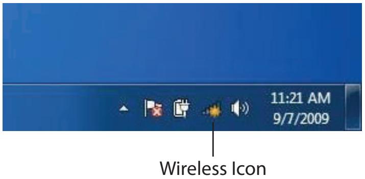
- The utility will display any available wireless networks in your area.
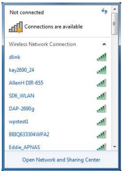
- Highlight the wireless network (SSID) you would like to connect to and click the Connect button.
If you get a good signal but cannot access the Internet, check your TCP/IP settings for your wireless adapter. Refer to the Networking Basics section in this manual for more information.
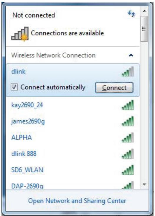
- The following window appears while your computer tries to connect to the router.
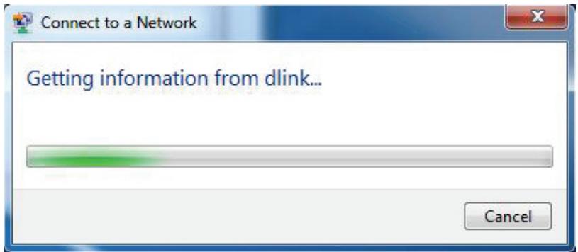
- Enter the same security key or passphrase that is on your router and click Connect. You can also connect by pushing the WPS button on the router.
It may take 20-30 seconds to connect to the wireless network. If the connection fails, please verify that the security settings are correct. The key or passphrase must be exactly the same as on the wireless router.
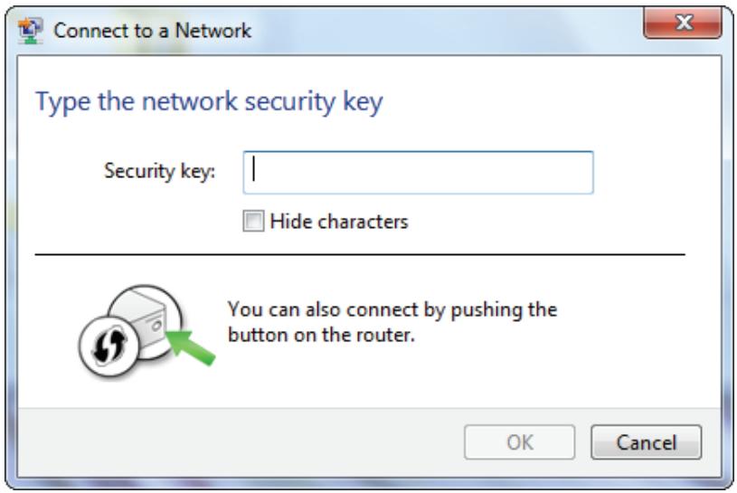
Troubleshooting
This chapter provides solutions to problems that can occur during the installation and operation of the DAP-3320. Read the following descriptions if you are having problems. (The examples below are illustrated in Windows XP. If you have a different operating system, the screenshots on your computer will look similar to the following examples.)
1. Why can't I access the web-based configuration utility?
When entering the IP address of the D-Link access point (dlinkapwxyz.local for example, with wxyz the last four digits of the AP's MAC Address), you are not connecting to a website on the Internet or have to be connected to the Internet. The device has the utility built-in to the device itself. Your computer must be on the same IP subnet to connect to the web-based utility.
-
Make sure you have an updated Java-enabled web browser. We recommend the following:
-
Microsoft Internet Explorer® 7 and higher
- Mozilla Firefox 12.0 and higher
- Google™ Chrome 20.0 and higher
-
Apple Safari 4 and higher
-
Verify physical connectivity by checking for solid link lights on the device. If you do not get a solid link light, try using a different cable or connect to a different port on the device if possible. If the computer is turned off, the link light may not be on.
-
Disable any Internet security software running on the computer. Software firewalls such as Zone Alarm, Black Ice, Sygate, Norton Personal Firewall, and Windows XP firewall may block access to the configuration pages. Check the help files included with your firewall software for more information on disabling or configuring it.
-
Configure your Internet settings:
-
Go to Start > Settings > Control Panel. Double-click the Internet Options Icon. From the Security tab, click the button to restore the settings to their defaults.
- Click the Connection tab and set the dial-up option to Never Dial a Connection. Click the LAN Settings button. Make sure nothing is checked. Click OK.
- Go to the Advanced tab and click the button to restore these settings to their defaults. Click OK three times.
-
Close your web browser (if open) and open it.
-
Access the web management. Open your web browser and enter the IP address of your D-Link access point in the address bar. This should open the login page for your the web management.
- If you still cannot access the configuration, unplug the power to the access point for 10 seconds and plug back in. Wait about 30 seconds and try accessing the configuration. If you have multiple computers, try connecting using a different computer.
2. What can I do if I forgot my password?
If you forgot your password, you must reset your access point. Unfortunately this process will change all your settings back to the factory defaults.
To reset the access point, locate the reset button (hole) on the rear panel of the unit. With the access point powered on, use a paperclip to hold the button down for 10 seconds. Release the button and the access point will go through its reboot process. Wait about 30 seconds to access the access point. The default IP address is 192.168.0.50. When logging in, the username is Admin and leave the password box empty.
3. Why can't I connect to certain sites or send and receive emails when connecting through my access point?
If you are having a problem sending or receiving email, or connecting to secure sites such as eBay, banking sites, and Hotmail, we suggest lowering the MTU in increments of ten (Ex. 1492, 1482, 1472, etc).
Note: AOL DSL+ users must use MTU of 1400.
To find the proper MTU Size, you'll have to do a special ping of the destination you're trying to go to. A destination could be another computer, or a URL.
- Click on Start and then click Run.
- Windows® 95, 98, and Me users type in command (Windows NT, 2000, and XP users type in cmd) and press Enter (or click OK).
- Once the window opens, you'll need to do a special ping. Use the following syntax:
ping [url] [-f] [-l] [MTU value]
Example: ping yahoo.com -f -l 1472
C:\>ping yahoo.com -f -l 1482
Pinging yahoo.com [66.94.234.13] with 1482 bytes of data:
Packet needs to be fragmented but DF set.
Packet needs to be fragmented but DF set.
Packet needs to be fragmented but DF set.
Packet needs to be fragmented but DF set.
Ping statistics for 66.94.234.13:
    Packets: Sent = 4, Received = 0, Lost = 4 (100% loss),
Approximate round trip times in milli-seconds:
    Minimum = 0ms, Maximum = 0ms, Average = 0ms
C:\>ping yahoo.com -f -l 1472
Pinging yahoo.com [66.94.234.13] with 1472 bytes of data:
Reply from 66.94.234.13: bytes=1472 time=93ms TTL=52
Reply from 66.94.234.13: bytes=1472 time=109ms TTL=52
Reply from 66.94.234.13: bytes=1472 time=125ms TTL=52
Reply from 66.94.234.13: bytes=1472 time=203ms TTL=52
Ping statistics for 66.94.234.13:
    Packets: Sent = 4, Received = 4, Lost = 0 (0% loss),
Approximate round trip times in milli-seconds:
    Minimum = 93ms, Maximum = 203ms, Average = 132ms
C:\>
You should start at 1472 and work your way down by 10 each time. Once you get a reply, go up by 2 until you get a fragmented packet. Take that value and add 28 to the value to account for the various TCP/IP headers. For example, lets say that 1452 was the proper value, the actual MTU size would be 1480, which is the optimum for the network we're working with (1452+28=1480).
Once you find your MTU, you can now configure your access point with the proper MTU size.
To change the MTU rate on your access point follow the steps below:
- Open your browser, enter the IP address of your access point (192.168.0.50) and click OK.
- Enter your username (Admin) and password (blank by default). Click OK to enter the web configuration page for the device.
- Click on Setup and then click Manual Configure.
- To change the MTU enter the number in the MTU field and click Save Settings to save your settings.
- Test your email. If changing the MTU does not resolve the problem, continue changing the MTU in increments of ten.
Wireless Basics
D-Link wireless products are based on industry standards to provide easy-to-use and compatible high-speed wireless connectivity within your home, business or public access wireless networks. Strictly adhering to the IEEE standard, the D-Link wireless family of products will allow you to securely access the data you want, when and where you want it. You will be able to enjoy the freedom that wireless networking delivers.
A wireless local area network (WLAN) is a cellular computer network that transmits and receives data with radio signals instead of wires. Wireless LANs are used increasingly in both home and office environments, and public areas such as airports, coffee shops and universities. Innovative ways to utilize WLAN technology are helping people to work and communicate more efficiently. Increased mobility and the absence of cabling and other fixed infrastructure have proven to be beneficial for many users.
Wireless users can use the same applications they use on a wired network. Wireless adapter cards used on laptop and desktop systems support the same protocols as Ethernet adapter cards.
Under many circumstances, it may be desirable for mobile network devices to link to a conventional Ethernet LAN in order to use servers, printers or an Internet connection supplied through the wired LAN. A Wireless Access point is a device used to provide this link.
What is Wireless?
Wireless or Wi-Fi technology is another way of connecting your computer to the network without using wires. Wi-Fi uses radio frequency to connect wirelessly, so you have the freedom to connect computers anywhere in your home or office.
D-Link is the worldwide leader and award winning designer, developer, and manufacturer of networking products. D-Link delivers the performance you need at a price you can afford. D-Link has all the products you need to build your network.
How does wireless work?
Wireless works similar to how cordless phone work, through radio signals to transmit data from one point A to point B. But wireless technology has restrictions as to how you can access the network. You must be within the wireless network range area to be able to connect your computer. There are two different types of wireless networks Wireless Local Area Network (WLAN), and Wireless Personal Area Network (WPAN).
Wireless Local Area Network (WLAN)
In a wireless local area network, a device called an Access Point (AP) connects computers to the network. The access point has a small antenna attached to it, which allows it to transmit data back and forth over radio signals. With an indoor access point as seen in the picture, the signal can travel up to 300 feet. With an outdoor access point the signal can reach out up to 30 miles to serve places like manufacturing plants, industrial locations, college and high school campuses, airports, golf courses, and many other outdoor venues.
Wireless Personal Area Network (WPAN)
Bluetooth is the industry standard wireless technology used for WPAN. Bluetooth devices in WPAN operate in a range up to 30 feet away.
Compared to WLAN the speed and wireless operation range are both less than WLAN, but in return it doesn't use nearly as much power which makes it ideal for personal devices, such as mobile phones, PDAs, headphones, laptops, speakers, and other devices that operate on batteries.
Who uses wireless?
Wireless technology has become so popular in recent years that almost everyone is using it, whether it's for home, office, business, D-Link has a wireless solution for it.
Home
- Gives everyone at home broadband access
- Surf the web, check email, instant message, etc.
- Gets rid of the cables around the house
- Simple and easy to use
Small Office and Home Office
- Stay on top of everything at home as you would at office
- Remotely access your office network from home
- Share Internet connection and printer with multiple computers
- No need to dedicate office space
Where is wireless used?
Wireless technology is expanding everywhere not just at home or office. People like the freedom of mobility and it's becoming so popular that more and more public facilities now provide wireless access to attract people. The wireless connection in public places is usually called "hotspots".
Using a D-Link Cardbus Adapter with your laptop, you can access the hotspot to connect to Internet from remote locations like: Airports, Hotels, Coffee Shops, Libraries, Restaurants, and Convention Centers.
Wireless network is easy to setup, but if you're installing it for the first time it could be quite a task not knowing where to start. That's why we've put together a few setup steps and tips to help you through the process of setting up a wireless network.
Tips
Here are a few things to keep in mind, when you install a wireless network.
Centralize your access point or Access Point
Make sure you place the bridge/access point in a centralized location within your network for the best performance. Try to place the bridge/access point as high as possible in the room, so the signal gets dispersed throughout your home. If you have a two-story home, you may need a Repeater to boost the signal to extend the range.
Eliminate Interference
Place home appliances such as cordless telephones, microwaves, wireless speakers, and televisions as far away as possible from the bridge/access point. This would significantly reduce any interference that the appliances might cause since they operate on same frequency.
Security
Don't let your next-door neighbors or intruders connect to your wireless network. Secure your wireless network by turning on the WPA or WEP security feature on the access point. Refer to product manual for detail information on how to set it up.
Wireless Modes
There are basically two modes of networking:
- Infrastructure - All wireless clients will connect to an access point or wireless bridge.
- Ad-Hoc – Directly connecting to another computer, for peer-to-peer communication, using wireless network adapters on each computer, such as two or more wireless network Cardbus adapters.
An Infrastructure network contains an Access Point or wireless bridge. All the wireless devices, or clients, will connect to the wireless bridge or access point.
An Ad-Hoc network contains only clients, such as laptops with wireless cardbus adapters. All the adapters must be in Ad-Hoc mode to communicate.
Networking Basics
Check your IP address
After you install your adapter, by default, the TCP/IP settings should be set to obtain an IP address from a DHCP server (i.e. wireless router) automatically. To verify your IP address, please follow the steps below.
Click on Start > Run. In the run box type cmd and click OK. (Windows® 7/Vista® users type cmd in the Start Search box.)
At the prompt, type ipconfig and press Enter.
This will display the IP address, subnet mask, and the default gateway of your adapter.
If the address is 0.0.0.0, check your adapter installation, security settings, and the settings on your router. Some firewall software programs may block a DHCP request on newly installed adapters.
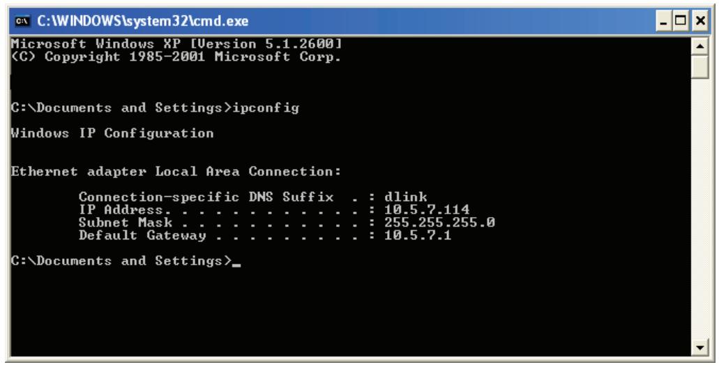
Statically Assign an IP address
If you are not using a DHCP capable gateway/router, or you need to assign a static IP address, please follow the steps below:
Step 1
Windows® 7 - Click on Start > Control Panel > Network and Internet > Network and Sharing Center > Change Adapter Setting.
Windows Vista - Click on Start > Control Panel > Network and Internet > Network and Sharing Center > Manage Network Connections.
Windows® XP - Click on Start > Control Panel > Network Connections.
Windows® 2000 - From the desktop, right-click My Network Places > Properties.
Step 2
Right-click on the Local Area Connection which represents your network adapter and select Properties.
Step 3
Highlight Internet Protocol (TCP/IP) and click Properties.
Step 4
Click Use the following IP address and enter an IP address that is on the same subnet as your network or the LAN IP address on your router.
Example: If the router's LAN IP address is 192.168.0.1, make your IP address 192.168.0.X where X is a number between 2 and 99. Make sure that the number you choose is not in use on the network. Set Default Gateway the same as the LAN IP address of your router (192.168.0.1).
Set Primary DNS the same as the LAN IP address of your router (192.168.0.1). The Secondary DNS is not needed or you may enter a DNS server from your ISP.
Step 5
Click OK twice to save your settings.
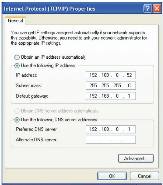
Technical Specifications
| DAP-3320 | ||
| Physical | LEDs | ■ Power |
| Device Interfaces | ■ 802.11n/g/b wireless ▪ One 10/100 LAN port (PoE support) | |
| Antenna | ■ Built-in 2 dBi antenna | |
| Wireless Frequency | ■ 2.4 GHz to 2.4835 GHz | |
| Maximum Transmit Power Outpu1 | ■ 29.55 dBm (901 mW) | |
| Operating voltage | ■ 48 V, 0.5A or 802.3af PoE compliant | |
| Maximum Power Consumption | ■ 5.6 watts | |
| Operating Temperature | ■ -20 to 60 °C (-4 to 140 °F) | |
| Storage Temperature | ■ -20 to 65 °C (-4 to 149 °F) | |
| Operating Humidity | ■ 0 to 90% (non-condensing) | |
| Storage Humidity | ■ 5 to 95% (non-condensing) | |
| Dimensions (L x W x H) | ■ 105.43 x 228.6 x 35.86 mm (4.15 x 9.00 x 1.41 inches) | |
| Weight | ■ 370.4 grams ▪ 384.25 grams (with mounting bracket) | |
| Dust/Water-Proof | ■ IP55 | |
| Functionality | Standards | ■ IEEE 802.11n/g/b ▪ IEEE 802.3u ▪ IEEE 802.3af |
| Network Management | ■ Web Browser Interface ▪ Traffic Control ▪ D-Link Central WiFiManager ▪ AP Array | |
| ■ HTTP, Secure HTTP (HTTPS) ▪ D-Link Central WiFiManager ▪ AP Array | ||
| ■ Telnet, Secure Telnet (SSH) ▪ AP Array | ||
| Security | ■ WPA-Personal & Enterprise ▪ SSID Broadcast disable ▪ MAC Address Control ▪ Network Access Protection (NAP) ▪ Internal Radius Server | |
| ■ WPA2-Personal & Enterprise ▪ WEP 64/128 bit Encryption ▪ Internal Radius Server | ||
| Operational Modes | ■ Access Point ▪ Wireless Distribution System with AP ▪ Wireless Client | |
| ■ Wireless Distribution System ▪ Wireless Client | ||
| Certifications | Safety & Emissions | FCCULWi-Fi Certified |
1 Range will vary depending on country's maximum transmit power output regulation. Maximum wireless signal rate derived from IEEE Standard 802.11g and 802.11n specifications. Actual data throughput will vary. Network conditions and environmental factors, including volume of network traffic, building materials and construction, and network overhead, lower actual data throughput rate. Environmental conditions will adversely affect wireless signal range.
Antenna Pattern
Antenna Pattern
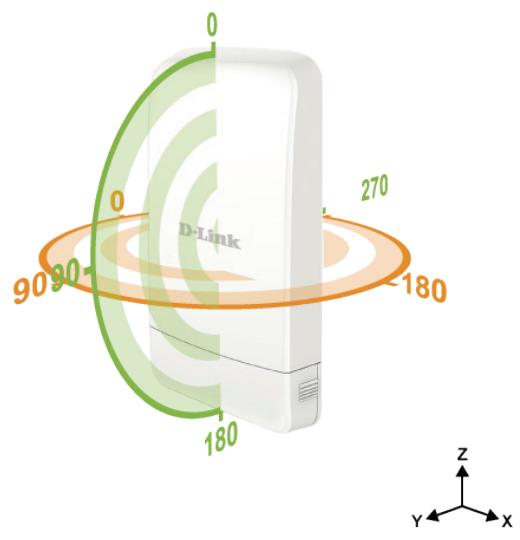
Orientation
2.4 GHz
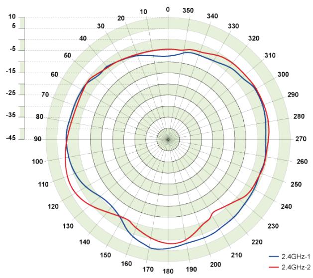
E-Plane
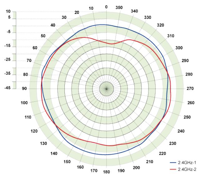
H-Plane
Regulatory Information
Caution: Do not remove the plug and connect it to a power outlet by itself; always attach the plug to the power adapter first before connecting it to a power outlet.
Federal Communication Commission Interference Statement:
This equipment has been tested and found to comply with the limits for a Class B digital device, pursuant to Part 15 of the FCC Rules. These limits are designed to provide reasonable protection against harmful interference in a residential installation. This equipment generates, uses and can radiate radio frequency energy and, if not installed and used in accordance with the instructions, may cause harmful interference to radio communications. However, there is no guarantee that interference will not occur in a particular installation. If this equipment does cause harmful interference to radio or television reception, which can be determined by turning the equipment off and on, the user is encouraged to try to correct the interference by one of the following measures:
- Reorient or relocate the receiving antenna.
- Increase the separation between the equipment and receiver.
- Connect the equipment into an outlet on a circuit different from that to which the receiver is connected.
- Consult the dealer or an experienced radio/TV technician for help.
Non-modifications Statement:
Any changes or modifications not expressly approved by the party responsible for compliance could void the user's authority to operate this equipment.
Caution:
This device complies with Part 15 of the FCC Rules. Operation is subject to the following two conditions: (1) This device may not cause harmful interference, and (2) this device must accept any interference received, including interference that may cause undesired operation.
For product available in the USA/Canada market, only channel 1~11 can be operated. Selection of other channels is not possible.
This device and its antenna(s) must not be co-located or operating in conjunction with any other antenna or transmitter except in accordance with FCC multi-transmitter product procedures.
Note:
The country code selection is for non-US model only and is not available to all US model. Per FCC regulation, all Wi-Fi product marketed in US must fixed to US operation channels only.
IMPORTANT NOTE:
FCC Radiation Exposure Statement:
This equipment complies with FCC radiation exposure limits set forth for an uncontrolled environment. This equipment should be installed and operated with minimum distance 20 cm between the radiator and your body.
Industry Canada Statement:
This device complies with Industry Canada licence-exempt RSS standard(s). Operation is subject to the following two conditions:
(1) this device may not cause interference, and
(2) this device must accept any interference, including interference that may cause undesired operation of the device.
Radiation Exposure Statement
This equipment complies with IC radiation exposure limits set forth for an uncontrolled environment. This equipment should be installed and operated with minimum distance 20 cm between the radiator & your body.
This device complies with the essential requirements of the R&TTE Directive 1999/5/EC. For more information, please refer to the Declaration of Conformity.
Notice of Wireless Radio LAN Usage in The European Community:
- At the time of writing this addendum, some countries such as Italy, Greece, Portugal and Spain have not allowed operation of radio devices in the 5 Ghz bands, although operation of 2.4 Ghz radio devices are allowed. Please check with your local authority to confirm.
- This device is restricted to indoor use when operated in the European Community using channels in the 5.15-5.35 GHz band to reduce the potential for interference.
- This device is a 2.4 GHz wideband transmission system (transceiver), intended for use in all EU member states and EFTA countries, except in France where restrictive use applies. This device may not be used for setting up outdoor radio links in France and in some areas the RF output power may be limited to 10mW EIR P in the frequency range of 2454 - 2483.5MHz . For detailed information the end-user should contact the national spectrum authority in France.
This equipment may be operated in AL, AD, BE, BG, DK, DE, FI, FR, GR, GW, IS, IT, HR, LI, LU, MT, MK, MD, MC, NL, NO, AT, OL, PT, RO, SM, SE, RS, SK, ES, CI, HU, CY
Usage Notes:
- To remain in conformance with European National spectrum usage regulations, frequency and channel limitations will be applied on the products according to the country where the equipment will be deployed.
- This device is restricted from functioning in Ad-hoc mode while operating in 5 Ghz. Ad-hoc mode is direct peer-to-peer communication between two client devices without an Access Point.
- Access points will support DFS (Dynamic Frequency Selection) and TPC (Transmit Power Control) functionality as required when operating in 5 Ghz within the EU.
2.4 GHz Wireless Frequency and Channel Operation in EEC Countries:

| Region | Frequency Band | Max output power (EIRP) |
| Metropolitan | 2400 - 2454 MHz | 100 mW |
| Guadeloupe, Martinique, St Pierre et Miquelon, Mayotte | 2454 - 2483.5 MHz | 100 mW indoor, 10 mW outdoor |
| Reunion et Guyane | 2400 - 2483.5 MHz | 100 mW |
| Rest of EU community | 2420 - 2483.5 MHz | 100 mW |
| R&TTE 1999/5/EC | |||
| WLAN 2.4 - 2.4835 GHz | |||
| IEEE 802.11b/g/n | |||
| Spectrum Regulation | MHz, Europa (ETSI) | max. EIRP Innenbereich | max. EIRP Außenbereich |
| Europa | 2400 - 2483.5 MHz | 100 mW | 100 mW |
| Frankreich | 2400 - 2454 MHz | 100 mW | 100 mW |
| 2454 - 2483.5 MHz | 100 mW | 10 mW | |
European Community Declaration of Conformity:
| Česky [Czech] | D-Link tímto prohlăšuje,Že tento DAP-3320 je ve shodě se základními požadavya dalšími príslušnými ustanoveními směrnice 1999/5/ES. |
| Dansk [Danish] | Undertegnede D-Link erklærer herved, at følgende udstyr DAP-3320 overholder de væsentlige krav og øvridge relevante krav i direktiv 1999/5/EF. |
| Deutsch [German] | Hiermit erklärt D-Link, dass sich das Gerät DAP-3320 in Übereinstimmung mit den grundlegenden Anforderungen und den übrigen einschlögigen Bestimmungen der Richtlinie 1999/5/EG befindet. |
| Eesti [Estonian] | Käesolevaga kinnitab D-Link seadme DAP-3320vastavust direktiivi 1999/5/EÜ pöhinõuetele ja nimetatud direktiivist tulenevatele teistele asjakohastele sâtetele. |
| English | Hereby, D-Link, declares that this DAP-3320 is in compliance with the essential requirements and other relevant provisions of Directive 1999/5/EC. |
| Espanol [Spanish] | Por medio de la presente D-Link declara que el DAP-3320 cumple con los requisitos esencias y cualessquiera除外 dispositions aplicables o exigibles de la Directiva 1999/5/CE. |
| Ελληνική [Greek] | METHN ΠΑΡΟΥΣΑ D-Link ΔΗΛΩNEI OTI DAP-3320 ΣΥΜΜΟΦΩNETAI ΠΙΝΟΤΙ ΟΥΣΙΩΔΕΙΣ ΑΠΑΙΤΗΣΕΙΣ KAI TΙΣ ΑΟΙΝΕΣ ΣχETAIKEΣ ΔΙATAΞΕΙΣ THΣ ΕΟΗΓΙΑΣ 1999/5/EK. |
| François [French] | Par la présente D-Link déclare que l'appareil DAP-3320 est conforme aux exigences essentielles et aux autres dispositions pertinentes de la directive 1999/5/CE. |
| Italiano [Italian] | Con la presente D-Link dichiara che questo DAP-3320 è conforme ai requisiti essenziali ed alle autres dispositions pertinenti stabilite alla direttiva 1999/5/CE. |
| Latviski [Latvian] | Ar šo D-Link deklare, ka DAP-3320 atbilst Direktīvas 1999/5/EK buttiskajām prasībām un citiem ar to saistītajiem noteikumiem. |
| Lietuviç [Lithuanian] | Šiuo D-Link deklaruoja, kad šis DAP-3320 atitinka esminius reikalavimus irKitas 1999/5/EB Direktyvos nuostatas. |
| Nederlands [Dutch] | Hierbij verklaart D-Link dat het toestel DAP-3320 in overeenstemming is met de essentiéle eisen en de andere relevante bepalingen van richtlijn 1999/5/EG. |
| Malti [Maltese] | Hawnhekk, D-Link, jiddikjara li dan DAP-3320 jikkonforma mal-ḥṭigijiet essenzjali u ma provvedimenti oḥrajn relevanti li hemm fid-Dirrettiva 1999/5/EC. |
| Magyar [Hungarian] | Alulírott, D-Link nyilatkozom, hogy a DAP-3320 megfelel a vonatkozó alapvető követelményeknek és az 1999/5/EC irányelv egyéb előírsainak. |
| Polski [Polish] | Niniejszym D-Link oświadcza, ze DAP-3320 jest zgodny z zasadniczymi wymogami oraz pozostałymi stosownymi postanowieniami Dyrektywy 1999/5/EC. |
| Português [Portuguese] | D-Link declara que este DAP-3320 está conforme com os requisitos essenciais e autres disponções da Directa 1999/5/CE. |
| Slovensko [Slovenian] | D-Link izjavlja, da je ta DAP-3320 v skladu z bistvenimi zahtevami in ostalimi relevantnimi dolocili direktive 1999/5/ES. |
| Slovensky [Slovak] | D-Link týmto vyhlasuje, ze DAP-3320 splína základné požiadavky a větky príslušné ustanovenia Smernice 1999/5/ES. |
| Suomi [Finnish] | D-Link vakuuttaa täten että DAP-3320 typpinen laite on direktiivin 1999/5/EY oleellisten vaatimusten ja sitä koskevien direktiivin muiden ehtojen mukainen. |
Warning Statement:
The power outlet should be near the device and easily accessible.

Safety Instructions
Please adhere to the following safety guidelines to help ensure your own personal safety and protect your system from potential damage. Any acts taken that are inconsistent with ordinary use of the product, including improper testing, etc., and those not expressly approved by D-Link may result in the loss of product warranty.
Unless expressly approved by an authorized representative of D-Link in writing, you may not and may not permit others to:
- Disassemble or reverse engineer the device or attempt to derive source code (underlying ideas, algorithms, or structure) from the device or from any other information provided by D-Link, except to the extent that this restriction is expressly prohibited by local law.
- Modify or alter the device.
- Remove from the device any product identification or other notices, including copyright notices and patent markings, if any. To reduce the risk of bodily injury, electrical shock, fire, and damage to the device and other equipment, observe the following precautions:
Power Sources
- Observe and follow service markings.
- Do not push any objects into the openings of your device unless consistent with the authorized operation of the device. Doing so can cause a fire or an electrical shock by shorting out interior components.
- The powering of this device must adhere to the power specifications indicated for this product.
- Do not overload wall outlets and/or extension cords as this will increase the risk of fire or electrical shock.
- Do not rest anything on the power cord or on the device (unless the device is made and expressly approved as suitable for stacking).
- Position system cables and power cables carefully; route cables so that they cannot be stepped on or tripped over. Be sure that nothing rests on any cables.
- Operate the device only from the type of external power source indicated on the electrical ratings label.
- To help avoid damaging your device, be sure the voltage selection switch (if provided) on the power supply is set to match the power available at your location.
- Also be sure that attached devices are electrically rated to operate with the power available in your location.
-
Use only approved power cable(s). If you have not been provided a power cable for your device or for any AC -powered option intended for your device, purchase a power cable that is approved for use in your country and is suitable for use with your device. The power cable must be rated for the device and for the voltage and current marked on the device's electrical ratings label. The voltage and current rating of the cable should be greater than the ratings marked on the device.
-
To help prevent an electrical shock, plug the device and peripheral power cables into properly grounded electrical outlets. These cables are equipped with three-prong plugs to help ensure proper grounding. Do not use adapter plugs or remove the grounding prong from a cable. If you must use an extension cable, use a 3-wire cable with properly grounded plugs.
- Observe extension cable and power strip ratings. Ensure that the total ampere rating of all products plugged into the extension cable or power strip does not exceed 80 percent of the ampere ratings limit for the extension cable or power strip.
- To help protect your device from sudden, transient increases and decreases in electrical power, use a surge suppressor, line conditioner, or uninterruptible power supply (UPS).
- Do not modify power cables or plugs. Consult a licensed electrician or your power company for site modifications. Always follow your local/national wiring rules.
- When connecting or disconnecting power to hot-pluggable power supplies, if offered with your device, observe the following guidelines.
- Install the power supply before connecting the power cable to the power supply.
- Unplug the power cable before removing the power supply.
- If the system has multiple sources of power, disconnect power from the device by unplugging all power cables from the power supplies.
Servicing/Disassembling
- Do not service any product except as expressly set forth in your system documentation.
- Opening or removing covers that are marked with the triangular symbol with a lightning bolt may expose you to an electrical shock. Only a trained service technician should service components inside these compartments.
- To reduce the risk of electrical shock, never disassemble this device. None of its internal parts are user-replaceable; therefore, there is no reason to access the interior.
- Do not spill food or liquids on your system components, and never operate the device in a wet environment. If the device gets wet, see the appropriate section in your troubleshooting guide or contact your trained service provider.
- Use the device only with approved equipment.
- Move products with care; ensure that all casters and/or stabilizers are firmly connected to the system. Avoid sudden stops and uneven surfaces.
Environment
- Do not use this device near water (e.g. near a bathtub, sink, laundry tub, fish tank, in a wet basement or near a swimming pool).
-
Do not use this device in areas with high humidity.
-
This device must not be subjected to water or condensation.
- Keep your device away from radiators and heat sources. Also, do not block cooling vents.
Cleaning
- Always unplug the power before cleaning this device.
- Do not use liquid or aerosol cleaners of any kind. Use only compressed air that is recommended for electronic devices.
- Use a dry cloth for cleaning.
Protecting Against Electrostatic Discharge
Static electricity can harm delicate components inside your system. To prevent static damage, discharge static electricity from your body before you touch any of the electronic components, such as the microprocessor. You can do so by periodically touching an unpainted metal surface on the chassis.
You can also take the following steps to help prevent damage from electrostatic discharge (ESD):
- When unpacking a static-sensitive component from its shipping carton, do not remove the component from the antistatic packing material until you are ready to install the component in your system. Just before unwrapping the antistatic packaging, be sure to discharge static electricity from your body.
- When transporting a sensitive component, first place it in an antistatic container or packaging.
- Handle all sensitive components in a static-safe area. If possible, use antistatic floor pads, workbench pads, and an antistatic grounding strap.
Environmental
This product may contain a battery. Recycle or dispose of batteries in accordance with the battery manufacturer's instructions and local/national disposal and recycling regulations. For more information, please refer to the warranty guide.
Disposing of and Recycling Your Product ENGLISH

This symbol on the product or packaging means that according to local laws and regulations this product should be not be disposed of in the household waste but sent for recycling. Please take it to a collection point designated by your local authorities once it has reached the end of its life, some will accept products for free. By recycling the product and its packaging in this manner you help to conserve the environment and protect human health.
D-Link and the Environment
At D-Link, we understand and are committed to reducing any impact our operations and products may have on the environment. To minimise this impact D-Link designs and builds its products to be as environmentally friendly as possible, by using recyclable, low toxic materials in both products and packaging.
D-Link recommends that you always switch off or unplug your D-Link products when they are not in use. By doing so you will help to save energy and reduce CO2 emissions.
To learn more about our environmentally responsible products and packaging please visit www.dlinkgreen.com
DEUTSCH DE

With the easy-to-use web-based interface you can…
- Configure once and apply to multiple Access Points
Install on Windows PC - Access on any device using a web-browser, e.g. smartphone or notebook
Utilise user authentication and access control - Monitor your entire wireless network in real time1
- Access detailed reports
- Optimise your bandwidth
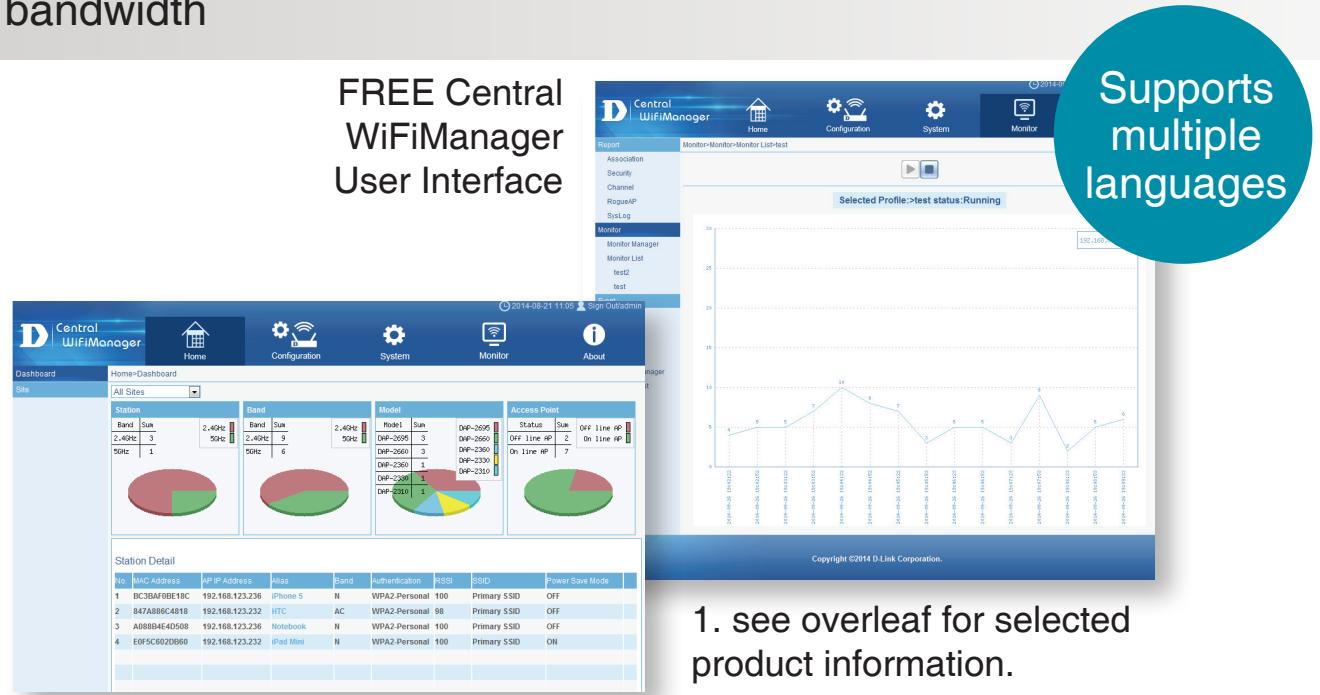

FREE Central WiFiManager
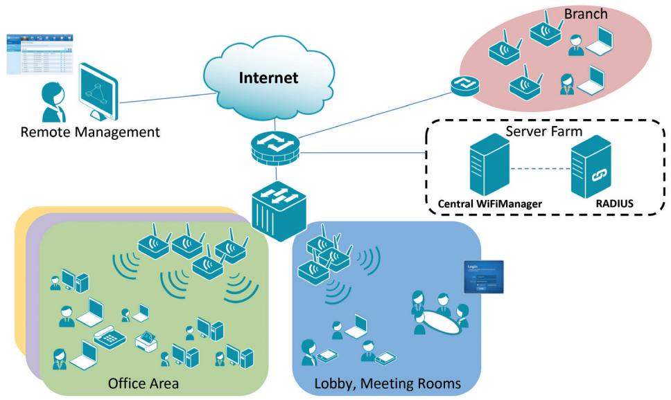
Available on the following products ^2 :
DAP-2695
Wireless AC1750 Indoor Access Poc
Designed to support small to medium business or enterprise environments.
Secure, manageable dual-band wireless LAN options.
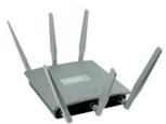
DAP-2660
Wireless AC1200 Indoor Ceiling Access Point
Providing enhanced speeds of Wireless AC as well as dual-band connectivity to reduce interference, for a faster and more efficient network.
DAP-2310
Wireless N Indoor Access Point
Ideal for creating or expanding capacity of a wireless network; mainly used in high-traffic areas such as airports, coffee shops, sports venues, and university campus deployments.
DAP-2360
Wireless N PoE Access Point
For advanced indoor installations, this high-speed Access Point has integrated PoE support, allowing installation in areas where power outlets are not readily available.
DAP-2690
Wireless N
Simultaneous
Dual-Band PoE Access Point
Designed for indoor installation where power outlets are not readily available. Enables deployment of a highly manageable, robust and secure wireless network.
DAP-2330
Wireless N PoE Access Point
Ideal for wireless networks in high-traffic areas such as airports, coffee shops, shopping centres, sporting venues, hotels and campus deployments. PoE offers installation where power outlets are not available.