
DWL-8710AP - Wireless Access Point D-LINK - Free user manual and instructions
Find the device manual for free DWL-8710AP D-LINK in PDF.
| Product Type | Wireless Access Point |
| Wireless Standard | IEEE 802.11ac Wave 2 (backward compatible with 802.11a/b/g/n) |
| Frequencies | 2.4 GHz and 5 GHz |
| Maximum Data Rate | Up to 867 Mbps on 5 GHz, 300 Mbps on 2.4 GHz |
| Number of Antennas | 2 × 2 MIMO integrated |
| Ports | 1 Gigabit Ethernet port (10/100/1000) with PoE (802.3af) |
| Power Supply | PoE (802.3af) or 12 V DC power adapter (optional) |
| Dimensions | 200 mm diameter × 40 mm thickness |
| Weight | 300 g |
| Mounting | Ceiling or wall (mounting kit included) |
| Wireless Security | WPA2/WPA3, MAC filtering, WLAN isolation, VLAN |
| Management | Web interface, SNMP v1/v2/v3, CLI (SSH/Telnet) |
| Operating Mode | Access point, WDS repeater, bridge |
| Operating Temperature | 0 °C to 40 °C |
| Humidity | 10 % to 90 % (non-condensing) |
| Certifications | IC, FCC, CE |
| Warranty | 2 years |
| Maintenance and Cleaning | Clean with a dry soft cloth; do not use chemicals |
| Spare Parts | Not applicable (no detachable parts) |
| Repairability | Contains no user-serviceable parts; contact technical support |
Frequently Asked Questions - DWL-8710AP D-LINK
User questions about DWL-8710AP D-LINK
0 question about this device. Answer the ones you know or ask your own.
Ask a new question about this device
Download the instructions for your Wireless Access Point in PDF format for free! Find your manual DWL-8710AP - D-LINK and take your electronic device back in hand. On this page are published all the documents necessary for the use of your device. DWL-8710AP by D-LINK.
USER MANUAL DWL-8710AP D-LINK
Quick Installation Guide
This document will guide you through the basic installation process for your new D-Link Access Point.
DWL-8710AP
natural_image
Pure electrical circuit lines without any symbolsBefore You Begin
This Quick Installation Guide gives you step-by-step instructions for setting up your DWL-8710AP 802.11n/ac Unified Wireless Outdoor Access Point. For more detailed information about the access point, configuring the device, and technical specifications, please refer to the User Manual.
Package Contents
This DWL-8710AP package should include the following items:
- DWL-8710AP
- 4 antennas
• 4 antenna connector caps
• Grounding wire and screw
• Wall mounting base plate - Pole mounting bracket
• CD-ROM with documentation
- Mounting kit (bolts, washers, nuts, screws, pole strap)
To power the DWL-8710AP, please use any D-Link IEEE 802.3at-compliant PoE switch or the D-Link DPE-101GI/ DPE-301GI PoE injector.
If any of the above items are damaged or missing, please contact your local D-Link reseller.
System Requirements
- CD-ROM drive
- Computer with Windows, Macintosh, or Linux-based operating system
• Installed and operational Ethernet adapter - Internet Explorer 6.0, Chrome 2.0, Safari 2.0, or Firefox 3.0 and above
Hardware Overview
LED Indicators
text_image
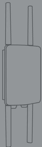
Power LAN1 LAN2 2.4GHz 5.0GHz 1 2 3 4Figure 1: Front panel LEDs
| # | LED | Status | Description |
| 1 | Power | On | Device is powered and working |
| 2 | LAN 1/2 | Blinking | Data is being processed |
| On | Port is connected to a device | ||
| 3 | 2.4 GHz | Blinking | Wireless data is being processed |
| On | AP is transmitting over 2.4 GHz | ||
| 4 | 5 GHz | Blinking | Wireless data is being processed |
| On | AP is transmitting over 5 GHz |
Table 1: LED overview
Bottom Interface Connectors
text_image
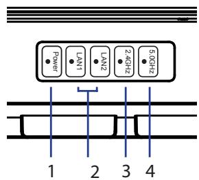
1 2 3 4Figure 2: Bottom panel connectors
| # | Connector | Description |
| 1 | 5 GHz | Antenna connector for the 5 GHz band antenna |
| 2 | LAN 1 | LAN and PoE input port |
| 3 | LAN 2 | Non-PoE LAN input port |
| 4 | 2.4 GHz | Antenna connector for the 2.4 GHz band antenna |
Table 2: Connector description
Top Interface Connectors
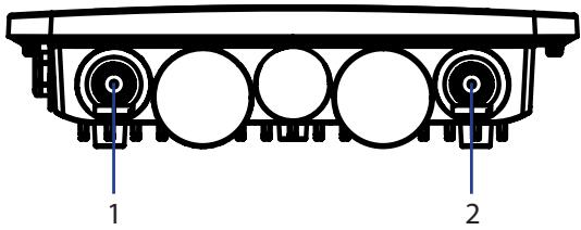
text_image
1 2Figure 3: Top panel connectors
| # | Connector | Description |
| 1 | 5 GHz | Antenna connector for the 5 GHz band antenna |
| 2 | 2.4 GHz | Antenna connector for the 2.4 GHz band antenna |
Table 3: Top connector description
Side Panel
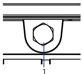
natural_image
Pure technical diagram of a mechanical component with no text or symbolsFigure 4: Side panel vent
| # | Item | Description |
| 1 | Vent | Repels liquid and particles while allowing air to pass through |
Table 4: Vent description
Grounding
Grounding in a cabling installation refers to connecting non-current carrying metal parts of conductors to a building's system ground (earth ground).
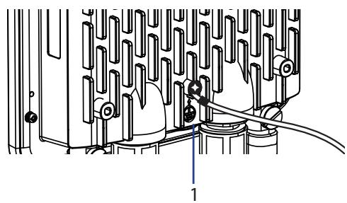
natural_image
Technical diagram of a mechanical assembly with no visible text or symbolsFigure 5: Ground connector
| # | item | Description |
| 1 | Ground Connector | Protects equipment from power surges. |
Table 5: Ground Connector description
Hardware Installation
Powering the Access Point
You can power the DWL-8710AP by connecting a PoE injector's PoE-OUT to the LAN1 port (PoE-Input) on the DWL-8710AP. Then connect the PoE injector's LAN-IN port to an available Ethernet port on your computer and plug in the injector's power cord into a power outlet as shown in figure 5.
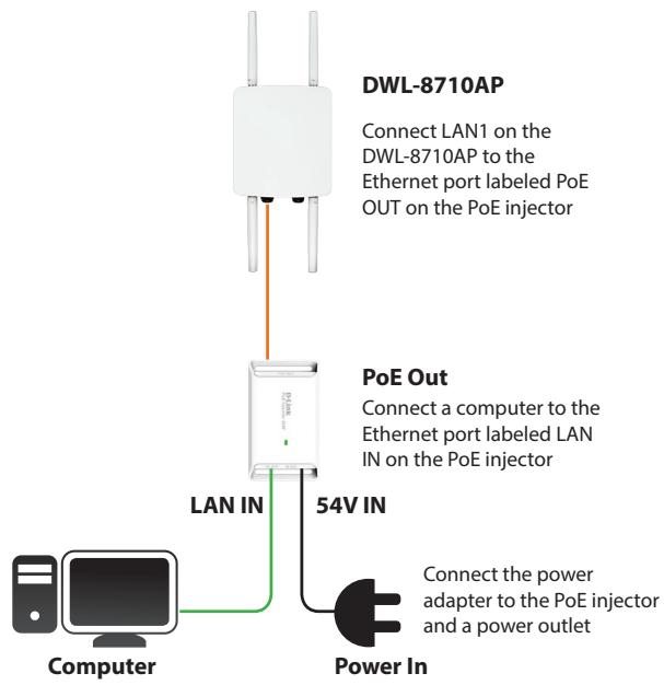
flowchart
graph TD
    A["Computer"] -->|54V IN| B["LAN IN"]
    B --> C["DWL-8710AP"]
    C -->|Connect LAN1 on the DWL-8710AP to the Ethernet port labeled PoE OUT on the PoE injector| D["POE Out"]
    D -->|Connect a computer to the Ethernet port labeled LAN IN on the PoE injector| E["Power In"]
    E -->|Connect the power adapter to the PoE injector and a power outlet| F["Power In"]
Figure 6: Powering with a PoE injector
Alternatively, you may directly connect the LAN1 (PoE-Input) port on the DWL-8710AP to any available PoE-capable port of an 802.3at-compliant PoE switch, as illustrated in figure 6.
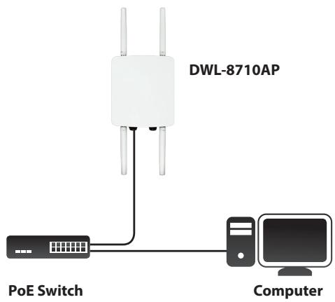
text_image
DWL-8710AP PoE Switch ComputerFigure7: Direct PoE powering
Protecting the Network Ports
The DWL-8710AP's Ethernet ports are equipped with a set of protective sealing caps designed for outdoor use. Please refer to figure 7 for how to correctly attach and secure the Ethernet cables to the DWL-8710AP.
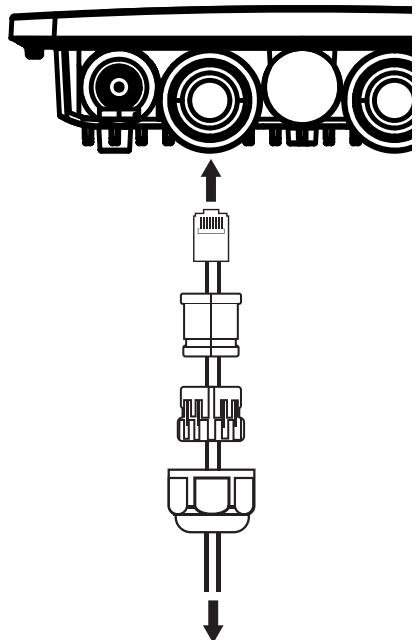
natural_image
Mechanical assembly diagram showing a piston-cylinder assembly with no text or symbolsFigure 8: Securing the Ethernet cable
Mounting the AP to a Wall
The DWL-8710AP can be mounted either horizontally or vertically. However, it is recommended that the AP is installed with the antennas positioned vertically in order to achieve optimal performance.
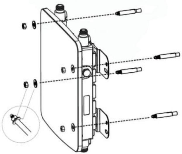
- Use the mounting base plate to mark the location on the surface where you want to mount the DWL-8710AP. Next, drill a hole of 8 mm wide and 37 mm deep on all 4 markings.
- Remove the nut and washer from the bolts and place the bolts in the holes as shown below in figure 8.
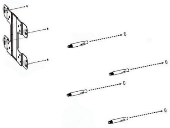
natural_image
Technical diagram showing exploded view of a mechanical bracket with multiple dashed lines indicating assembly or alignment (no text or symbols present)Figure 9: Preparing the mounting location
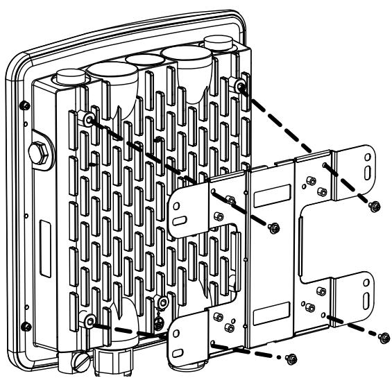
- Place and lock the flat washer on the cap screws and attach the mounting plate to the back of the DWL-8710AP using the screws as illustrated in figure 9.
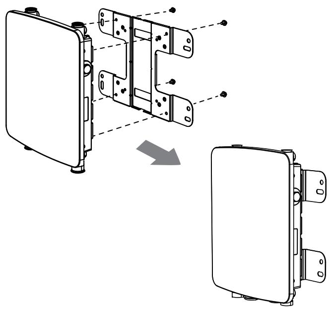
natural_image
Technical illustration of a device's internal components, showing exploded view and disassembled assembly (no text or symbols)Figure 10: Mounting the base plate
- Mount the DWL-8710AP onto the bolts that were placed in the wall, then fasten the bolts' flat washers and nuts to secure the mounting plate with the AP to the wall surface.
text_image
Technical diagram of a mechanical assembly with labeled parts and an inset detail view showing a pin alignment.Figure 11: Securing the AP
- Remove the protective caps covering the antenna ports on the AP, if any. Next, connect the 2 antennas marked "2.4 GHz" to the designated 2.4 GHz connectors and the antennas marked "5 GHz" to the designated 5 GHz connectors on the AP. The DWL-8710AP is now ready to be connected to the network.
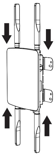
natural_image
Diagram of a mechanical device with four vertical supports and three horizontal arrows indicating directional movement (no text or symbols)Figure 12: Attaching the antennas
Mounting the AP to a Pole
The DWL-8710AP can be mounted either horizontally or vertically. However, it is recommended that the AP is installed with the antennas positioned vertically in order to achieve optimal performance.
- Place the lock and flat washer on the cap screws and attach the mounting plate to the back of the DWL-8710AP.
natural_image
Technical line drawing of a mechanical housing or enclosure with internal components and mounting holes (no text or symbols)Figure 13: Mounting the base plate
- Depending on the orientation of the pole you wish to install the AP onto (horizontal or vertical), attach the pole mounting bracket to the mounting base plate accordingly using the screws. Refer to figure 13 for the proper position of the pole mounting bracket for each direction.
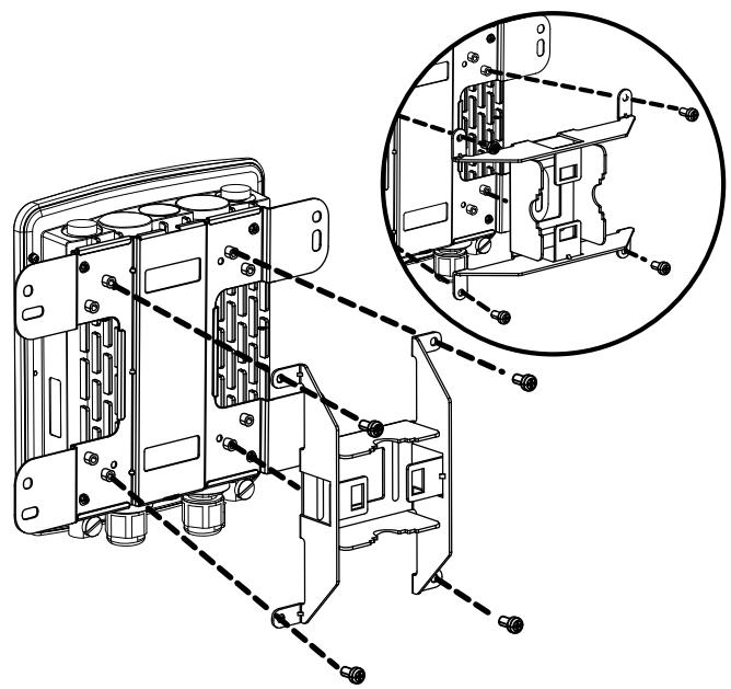
natural_image
Technical line drawing of a mechanical assembly with multiple components and a magnified inset showing internal structure (no text or symbols)Figure 14: Attaching the pole mount base
- Thread the open end of the pole strap through the two tabs on the pole mounting bracket to secure the strap to the mounting bracket.
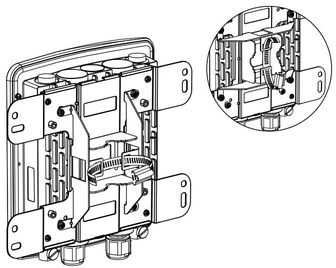
natural_image
Technical line drawing of a mechanical device housing with internal components and an inset close-up view (no text or symbols)Figure 15: Attaching the pole strap
- Choose the location where you want to mount the AP and place the strap around the pole. Tighten and lock the strap to secure the pole mount bracket with the AP to the pole.
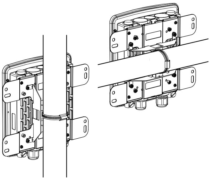
natural_image
Technical line drawing of a mechanical assembly with two views (top and side), showing internal components and mounting holes (no text or symbols)Figure 16: AP placement orientation
- Remove the protective caps covering the antenna ports on the AP, if any. Next, attach the 2 antennas marked "2.4 GHz" to the designated 2.4 GHz connectors and the 2 antennas marked "5 GHz" to the designated 5 GHz connectors on the AP. The DWL-8710AP is now ready to be connected to the network.

natural_image
Technical diagram of a mechanical assembly with directional arrows indicating movement or force (no text or symbols present)Figure 17: Attaching the antennas
Configuring the Access Point
To configure the DWL-8710AP, simply connect the AP directly to a computer and configure it through its Graphical User Interface (GUI).
For more detailed information on how to set up and configure the DWL-8710AP, please refer to the User Manual.
- Choose the location where you want to mount the AP and place the strap around the pole. Tighten and lock the strap to secure the pole mount bracket with the AP to the pole.

natural_image
Technical line drawing of a mechanical assembly with two views (top and side), showing internal components and mounting brackets (no text or symbols)Figure 16: AP placement orientation
- Remove the protective caps covering the antenna ports on the AP, if any. Next, attach the 2 antennas marked "2.4 GHz" to the designated 2.4 GHz connectors and the 2 antennas marked "5 GHz" to the designated 5 GHz connectors on the AP. The DWL-8710AP is now ready to be connected to the network.
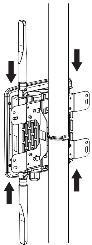
natural_image
Technical diagram of a mechanical device with directional arrows indicating assembly or movement (no text or symbols present)Figure 17: Attaching the antennas
Configuring the Access Point
To configure the DWL-8710AP, simply connect the AP directly to a computer and configure it through its Graphical User Interface (GUI).
For more detailed information on how to set up and configure the DWL-8710AP, please refer to the User Manual.
Federal Communication Commission Interference Statement
This equipment has been tested and found to comply with the limits for a Class B digital device, pursuant to Part 15 of the FCC Rules. These limits are designed to provide reasonable protection against harmful interference in a residential installation. This equipment generates, uses and can radiate radio frequency energy and, if not installed and used in accordance with the instructions, may cause harmful interference to radio communications. However, there is no guarantee that interference will not occur in a particular installation. If this equipment does cause harmful interference to radio or television reception, which can be determined by turning the equipment off and on, the user is encouraged to try to correct the interference by one of the following measures:
- Reorient or relocate the receiving antenna.
- Increase the separation between the equipment and receiver.
- Connect the equipment into an outlet on a circuit different from that to which the receiver is connected.
- Consult the dealer or an experienced radio/TV technician for help.
FCC Caution: Any changes or modifications not expressly approved by the party responsible for compliance could void the user's authority to operate this equipment.
This device complies with Part 15 of the FCC Rules. Operation is subject to the following two conditions: (1) This device may not cause harmful interference, and (2) this device must accept any interference received, including interference that may cause undesired operation.
This transmitter must not be co-located or operating in conjunction with any other antenna or transmitter.
IMPORTANT NOTE:
FCC Radiation Exposure Statement:
This equipment complies with FCC radiation exposure limits set forth for an uncontrolled environment. This equipment should be installed and operated with minimum distance 24cm between the radiator & your body.
Industry Canada statement:
This device complies with Industry Canada licence-exempt RSS standard(s). Operation is subject to the following two conditions: (1) this device may not cause interference, and (2) this device must accept any interference, including interference that may cause undesired operation of the device.
(i) the device for operation in the band 5150-5250 MHz is only for indoor use to reduce the potential for harmful interference to co-channel mobile satellite systems;
(ii) high-power radars are allocated as primary users (i.e. priority users) of the bands 5250-5350 MHz and 5650-5850 MHz and that these radars could cause interference and/or damage to LE-LAN devices.
Avertissement:
Radiation Exposure Statement:
This equipment complies with IC radiation exposure limits set forth for an uncontrolled environment. This equipment should be installed and operated with minimum distance 30cm between the radiator & your body.
This radio transmitter (IC: 4216A-WL8710APA1) has been approved by Industry Canada to operate with the antenna types listed below with the maximum permissible gain and required antenna impedance for each antenna type indicated. Antenna types not included in this list, having a gain greater than the maximum gain indicated for that type, are strictly prohibited for use with this device.
Antenna information
| Frequency | Band | Model | Type | Connector | Gain(dBi) |
| 2.4GHz | Master Wave | 95615MNXX003 | Dipole | N Plug | 4.92 |
| 5GHz | Master Wave | 95615MNXX005 | Dipole | N Plug | 6.92 |
Professional installation instruction (for FCC)
1. Installation personal
This product is designed for specific application and needs to be installed by a qualified personal who has RF and related rule knowledge. The general user shall not attempt to install or change the setting.
2. Installation location
The product shall be installed at a location where the radiating antenna can be kept 24cm from nearby person in normal operation condition to meet regulatory RF exposure requirement.
3. External antenna
Use only the antennas which have been approved by the applicant. The non-approved antenna(s) may produce unwanted spurious or excessive RF transmitting power which may lead to the violation of FCC limit and is prohibited.
4. Installation procedure
Please refer to user's manual for the detail.
5. Warning
Please carefully select the installation position and make sure that the final output power does not exceed the limit set force in relevant rules. The violation of the rule could lead to serious federal penalty.
Professional installation instruction (for IC)
1. Installation personal
This product is designed for specific application and needs to be installed by a qualified personal who has RF and related rule knowledge. The general user shall not attempt to install or change the setting.
2. Installation location
The product shall be installed at a location where the radiating antenna can be kept 30cm from nearby person in normal operation condition to meet regulatory RF exposure requirement.
3. External antenna
Use only the antennas which have been approved by the applicant. The non-approved antenna(s) may produce unwanted spurious or excessive RF transmitting power which may lead to the violation of IC limit and is prohibited.
4. Installation procedure
Please refer to user's manual for the detail.
5. Warning
Please carefully select the installation position and make sure that the final output power does not exceed the limit set force in relevant rules. The violation of the rule could lead to serious federal penalty.