DM-100 - Multimeter GREENLEE - Free user manual and instructions
Find the device manual for free DM-100 GREENLEE in PDF.

| Product type | Digital multimeter |
| Brand | GREENLEE |
| Model | DM-100 |
| Display | LCD 3200 counts + 70-segment bar graph |
| DC Voltage | 320 mV to 1000 V, accuracy ±0.5%+2 digits |
| AC Voltage | 3.2 V to 750 V, accuracy ±1.5%+5 digits (40-500 Hz) |
| DC Current | 320 µA to 10 A, accuracy ±1.7%+0.2 µA |
| AC Current | 320 µA to 10 A, accuracy ±2.2%+0.5 µA |
| Resistance | 320 Ω to 32 MΩ, accuracy ±0.75%+0.3 Ω |
| Diode test | Test voltage < 3.1 V, current 1.5 mA |
| Continuity test | Threshold ~30 Ω, tone, response time 100 ms |
| Auto power off | After about 10 minutes of inactivity |
| Power supply | 2 AAA 1.5 V batteries (NEDA 24A or IEC LR03) |
| Battery life | About 500 hours (alkaline batteries) |
| Overvoltage category | CAT III 600 V, CAT II 1000 V |
| Fuse | 16 A / 500 V HBC, 1/4 x 1-1/4 inch |
| Dimensions (approx.) | Approximately 150 x 70 x 30 mm |
| Weight (approx.) | Approximately 200 g (with batteries) |
| Maintenance | Clean with a damp cloth and mild detergent; do not use solvents |
| Repairability | No user-serviceable parts (except batteries and fuse); contact Greenlee |
| Warranty | Limited lifetime warranty for the original purchaser |
| Included accessories | Test leads, instruction manual |
Frequently Asked Questions - DM-100 GREENLEE
User questions about DM-100 GREENLEE
0 question about this device. Answer the ones you know or ask your own.
Ask a new question about this device
Download the instructions for your Multimeter in PDF format for free! Find your manual DM-100 - GREENLEE and take your electronic device back in hand. On this page are published all the documents necessary for the use of your device. DM-100 by GREENLEE.
USER MANUAL DM-100 GREENLEE
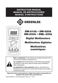
INSTRUCTION MANUAL MANUAL DE INSTRUCCIONES MANUEL D'INSTRUCTIONS

GREENLEE®
DM-100 • DM-110
DIGITAL MULTIMETERS MULTIMETROS DIGITALES
MULTIMETRES NUMERIQUES

Read and understand all of the instructions and safety information in this manual before operating or servicing this tool.
The Greenlee DM-100 and DM-110 Digital Multimeters are hand-held testing devices with the following measurement capabilities: AC and DC voltage, AC and DC current, and resistance. They also check diodes and verify continuity. In addition, the DM-110 measures frequency and capacitance. The DM-110 is a true RMS reading meter.
Both models feature automatic power off to conserve the batteries and a bar graph display which is more sensitive than the numeric display—useful for detecting faulty contacts, potentiometer clicks, and signal spikes.
Safety
Safety is essential in the use and maintenance of Greenlee tools and equipment. This instruction manual and any markings on the tool provide information for avoiding hazards and unsafe practices related to the use of this tool. Observe all of the safety information provided.
Purpose
This instruction manual is intended to familiarize all personnel with the safe operation and maintenance procedures for Greenlee DM-100 and DM-110 Digital Multimeters.
Keep this manual available to all personnel.
Replacement manuals are available upon request at no charge.
Greenlee and are registered trademarks of Greenlee Textron.
Important Safety Information

SAFETY ALERT SYMBOL
This symbol is used to call your attention to hazards or unsafe practices which could result in an injury or property damage. The signal word, defined below, indicates the severity of the hazard. The message after the signal word provides information for preventing or avoiding the hazard.
DANGER
Immediate hazards which, if not avoided, WILL result in severe injury or death.
WARNING
Hazards which, if not avoided, COULD result in severe injury or death.
CAUTION
Hazards or unsafe practices which, if not avoided, MAY result in injury or property damage.

WARNING
Read and understand this material before operating or servicing this equipment. Failure to understand how to safely operate this tool can result in an accident causing serious injury or death.
Important Safety Information

WARNING
Electric shock hazard:
Contact with live circuits can result in severe injury or death.
WARNING
Electric shock and fire hazard:
- Do not expose this unit to rain or moisture.
- Do not use the unit if it is wet or damaged.
- Use test leads or accessories that are appropriate for the application. See the category and voltage rating of the test lead or accessory.
- Inspect the test leads or accessory before use. They must be clean and dry, and the insulation must be in good condition.
- Use this unit for the manufacturer's intended purpose only, as described in this manual. Any other use can impair the protection provided by the unit.
Failure to observe these warnings can result in severe injury or death.
WARNING
Electric shock hazard:
- Do not apply more than the rated voltage between any two input terminals, or between any input terminal and earth ground.
- Do not contact the test lead tips or any uninsulated portion of the accessory.
Failure to observe these warnings can result in severe injury or death.
WARNING
- Do not operate with the case open.
- Before opening the case, remove the test leads from the circuit and shut off the unit.
Failure to observe these warnings can result in severe injury or death.
Important Safety Information
WARNING
The fuse is an integral part of the overvoltage protection. When fuse replacement is necessary, see Specifications for the correct type, size, and capacity. Using any other type of fuse will void the overvoltage protection rating of the unit.
Failure to observe this warning can result in severe injury or death.
CAUTION
Do not change the measurement function while the test leads are connected to a component or circuit.
Failure to observe this precaution can result in injury and can damage the unit.
CAUTION
- Do not attempt to repair this unit. It contains no user-serviceable parts.
- Do not expose the unit to extremes in temperature or high humidity. See Specifications.
Failure to observe these precautions can result in injury and can damage the unit.
IMPORTANT
- Unless measuring voltage, current, or frequency, shut off and lock out power.
Make sure that all capacitors are discharged. Voltage must not be present. - Set the selector and connect the test leads so that they correspond to the intended measurement. Incorrect settings or connections can result in a blown fuse.
- Using this unit near equipment that generates electromagnetic interference can result in unstable or inaccurate readings.
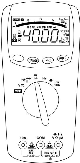
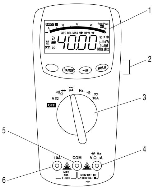
Identification
- Display 4-digit LCD and bar graph
- Function Buttons See explanations under Using the Features
- Selector Selects a function or turns power OFF
- - Hz Positive input terminal for all measurements except 10 A current VΩμA (−Hz on DM-110 only)
5.COM Negative, common or ground input terminal for all measurements - 10A Positive input terminal for current measurements up to 10 A
Symbols on the Unit

Warning—Read the instruction manual

Battery

Fuse

Double insulation
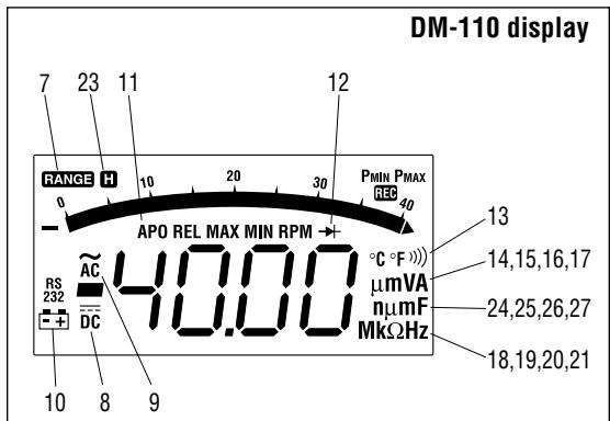
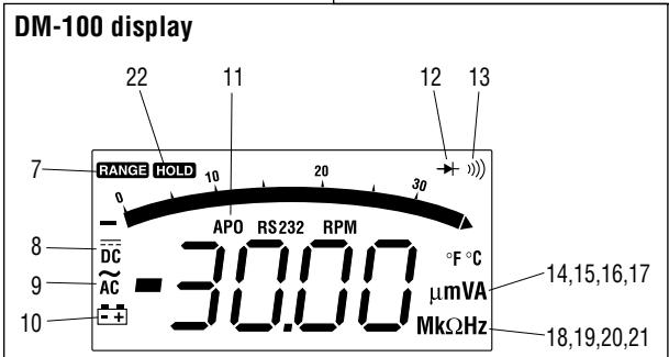
Display Icons
Both Models
- RANGE Manual range is selected
- DC measurement is selected
- AC measurement is selected
- Low battery
- APO Auto Power Off is enabled
- Diode
- Continuity is selected
- μ Micro (10-6)
- m Milli (10^-3)
- V Volts
- A Amps
- M Mega (10^6)
- k Kilo (10^3)
- Ω Ohms
- Hz Hertz (frequency or cycles per second)
DM-100 Only
- HOLD Hold function is enabled
DM-110 Only
- H Hold function is enabled
- n nano (10^-9)
- Micro (10-6)
- m Milli (10^-3)
- F Farads
Note: Unidentified icons are not used on these models.
AC Measurement
AC measurements are usually displayed as RMS (root-mean-square) values. Two AC measurement methods are average-responding RMS calibrated and true RMS-reading.
The average-responding RMS calibrated method takes the average value of the input signal, multiplies it by 1.11, and displays the result. This method is accurate if the input signal is a pure sine wave. The Greenlee DM-100 is an average-responding meter.
The true RMS-reading method uses internal circuitry to read the true RMS value. This method is accurate, within the specified crest factor limitations, whether the input signal is a pure sine wave, a square wave, triangle wave, half wave or signal with harmonics. The ability to read true RMS provides much more measurement versatility. The Greenlee DM-110 is a true RMS meter.
The Waveforms and Crest Factors table shows some typical AC signals and their RMS values.
Waveforms and Crest Factors
| Waveform | ||||
| RMS Value | 100 | 100 | 100 | 100 |
| Average Value | 90 | 100 | 87 | 64 |
| Crest Factor* (ξ) | 1.414 | 1 | 1.73 | 2 |
- The crest factor is the ratio of the peak value to the RMS value; it is represented by the Greek letter .
Using the Features
| Button | Press momentarily to: | Notes: |
| Blue(no label) | ·select AC or DC when measuring current or voltage ·select secondary functions | |
| RANGE | ·change from autoranging to manual ranging ·select ranges when using the manual ranging mode ·select trigger levels when measuring frequency | Press and hold to change from manual ranging to autoranging. |
| PWR RST(DM-100 only) | turn power back on after auto power off | |
| ~ Hz(DM-110 only) | view the frequency while measuring AC voltage or current | While in the Hz mode, the RANGE button does not change the frequency range. However, it changes the voltage range. |
| HOLD | hold a measured value for all functions. Press again to return to normal mode | Conversions are made but the display does not update. |
Operation
- See the Settings Table. Set the selector to the proper setting, press the unlabeled blue button to select the desired measurement, and connect the test leads to the meter. Start with the highest measurement setting.
- See Typical Measurements for specific measurement instructions.
-
Test the unit on a known functioning circuit or component.
-
If the unit does not function as expected on a known functioning circuit, replace the battery and/or fuse.
-
If the unit still does not function as expected, send the unit to Greenlee for repair. See the address shown under Warranty.
-
Take the reading from the circuit or component to be tested. If the resolution is not satisfactory, remove the meter from the circuit and change to the next lower range if using manual ranging.
Operation (cont'd)
Settings Table
| To measure this ... | set the selector to this symbol ... | this icon will appear on the display ... | connect the red lead to ... | and connect the black lead to ... |
| Capacitance* (DM-110 only) | -1- | F | -1- Hz VΩμA | COM |
| Continuity** | Ω →+ and press the BLUE button one time | ···) | VΩμA | COM |
| Current (AC)† | ~ μA and press the BLUE button one time | AC μA | VΩμA | COM |
| Current (DC)† | ~ μA | DC μA | VΩμA | COM |
| Current (AC) (10 A max) | ~ 10A and press the BLUE button one time | AC A | 10 A | COM |
| Current (DC) (10 A max) | ~ 10A | DC A | 10 A | COM |
| Diode*** | Ω ···→+ and press the BLUE button two times | →+ V | VΩμA | COM |
| Frequency (DM-110 only) | Hz | kHz or MHz | -1- Hz VΩμA | COM |
| Resistance | Ω ···) →+ | MΩ or kΩ | VΩμA | COM |
| Voltage (AC) | V ≈ and press the BLUE button one time | AC mV or V | VΩμA | COM |
| Voltage (DC) | V ≈ | DC mV or V | VΩμA | COM |
- Discharge capacitor before measurement.
Tone sounds if the measured resistance is less than approximately 30 Ω.
* Diode voltage is shown if conducting, or “OL” is displayed for non-conductance.
3200 A max for DM-100, 4000 A max for DM-110.
Operation (cont'd)
Auto Power Off
The meter defaults to automatically turn itself off after a period of inactivity from the user.
APO on the display indicates that the feature is enabled. The meter beeps approximately 15 seconds prior to turning off. The DM-100 turns off after 10 minutes, and the DM-110 turns off after 30 minutes. The present reading is held in memory. To turn the meter back on, press any button or turn the selector. The last reading will be displayed in the Hold mode. Press HOLD to return to normal operation.
Disabling Auto Power Off
To disable the Auto Power Off feature, press and hold the RANGE button while turning the meter on.
Note: When the meter is turned off and back on with the selector, the meter returns to the default. However, the last value is not held in memory.
Typical Measurements
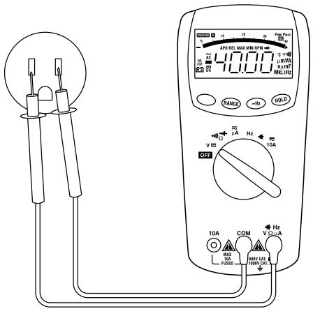
Voltage Measurement
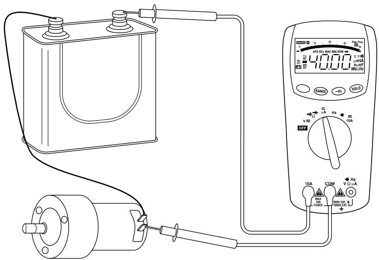
Current Measurement
Typical Measurements (cont'd)
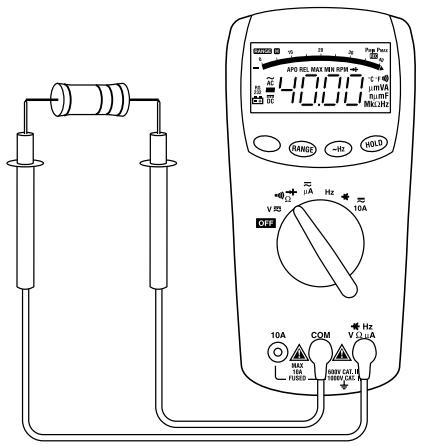
Resistance Measurement
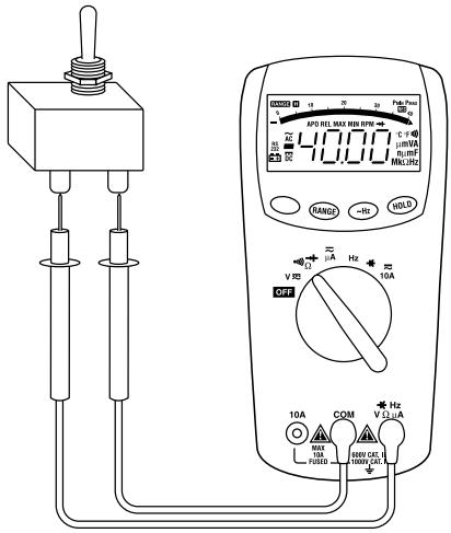
Continuity Check
Typical Measurements (cont'd)
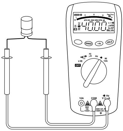
Capacitance Measurement
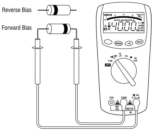
Diode Measurement
Accuracy: DM-100
See the Specifications section for operating conditions and temperature coefficient.
Accuracy is specified as follows: ± (a percentage of the reading + a fixed amount) at 23^ ± 5^ ( 73.4^ ± 9^ ), 0% to 80% relative humidity.
For the DM-100, AC accuracy is specified for sine waves only.
AC Current
| Range* | Accuracy | Burden Voltage |
| 320.0 μA | ± (2.2% + 0.5 μA) | 1 V max |
| 3200 μA | ± (2.2% + 5 μA) | 10 V max |
| 10.00 A | ± (2.5% + 0.05 A) | 2 V max |
AC Voltage
| Range* | Accuracy | Frequency Range | Input Impedance |
| 3.200 V | ± (1.50% + 0.005 V) | 40 to 500 Hz | 10 MΩ, 100 pF |
| 32.00 V | ± (1.50% + 0.05 V) | ||
| 320.0 V | ± (1.50% + 0.5 V) | ||
| 750 V | ± (1.50% + 5 V) |
DC Current
| Range* | Accuracy | Burden Voltage |
| 320.0 μA | ± (1.7% + 0.2 μA) | 1 V max |
| 3200 μA | ± (1.7% + 2 μA) | 10 V max |
| 10.00 A | ± (2% + 0.02 A) | 2 V max |
- In autorange mode, ranges change at approximately 3200 counts.
In manual range mode, range extends to 3400 counts.
Accuracy: DM-100 (cont'd)
DC Voltage
| Range* | Accuracy | Input Impedance |
| 320.0 mV | ± (0.5% + 0.2 mV) | over 1000 MΩ |
| 3.200 V | ± (0.5% + 0.002 V) | 10 MΩ |
| 32.00 V | ± (0.5% + 0.02 V) | |
| 320.0 V | ± (0.5% + 0.2 V) | |
| 1000 V | ± (0.5% + 2 V) |
Resistance
| Range* | Accuracy |
| 320.0 Ω | ± (1% + 0.4 Ω) |
| 3.200 kΩ | ± (0.75% + 0.003 kΩ) |
| 32.00 kΩ | ± (0.75% + 0.03 kΩ) |
| 320.0 kΩ | ± (0.75% + 0.3 kΩ) |
| 3.200 MΩ | ± (1% + 0.003 MΩ) |
| 32.00 MΩ | ± (2% + 0.05 MΩ) |
Typical open circuit voltage: 1.5V
- In autorange mode, ranges change at approximately 3200 counts.
In manual range mode, range extends to 3400 counts.
Diode Test
Test Current (Typical): 1.5mA
Open Circuit Voltage: Less than 3.1 VDC
Continuity
Threshold: Tone sounds if the measured resistance is less than approximately 30
Response Time: Approximately 100 ms
Accuracy: DM-110
See the Specifications section for operating conditions and temperature coefficient.
Accuracy is specified as follows: ± (a percentage of the reading + a fixed amount) at 23^ ± 5^ ( 73.4^ ± 9^ ), 0% to 80% relative humidity.
For the DM-110, AC accuracy specification applies for sine waves at full scale and non-sine waves below half scale.
- For crest factors from 1.4 to 3, add 1.5% to accuracy.
- For crest factors from 3 to 4, add 3% to accuracy.
AC Current
| Range | Accuracy | Burden Voltage |
| 400.0 μA | ± (2.2% + 0.5 μA) | 1 V max |
| 4000 μA | ± (2.2% + 5 μA) | 10 V max |
| 10.00 A * | ± (2.5% + 0.05 A) | 2 V max |
- 10 A continuous; 20 A maximum (Duty Cycle: 30 seconds on, 5 minutes off)
AC Voltage
| Range | Accuracy | Frequency Range | Input Impedance |
| 400.0 mV | unspecified | 40 to 500 Hz | 10 MΩ, 100 pF |
| 4.000 V | ± (1.5% + 0.005 V) | ||
| 40.00 V | ± (1.3% + 0.05 V) | ||
| 400.0 V | ± (1.3% + 0.5 V) | ||
| 750 V | ± (1.3% + 5 V) |
DC Current
| Range | Accuracy | Burden Voltage |
| 400.0 μA | ± (1.7% + 0.2 μA) | 1 V max |
| 4000 μA | ± (1.7% + 2 μA) | 10 V max |
| 10.00 A | ± (2% + 0.02 A) | 2 V max |
| Range | Accuracy | Input Impedance |
| 400.0 mV | ± (0.5% + 0.2 mV) | over 1000 MΩ |
| 4.000 V | ± (0.5% + 0.002 V) | 10 MΩ |
| 40.00 V | ± (0.5% + 0.02 V) | |
| 400.0 V | ± (0.5% + 0.2 V) | |
| 1000 V | ± (0.5% + 2 V) |
Resistance
| Range | Accuracy |
| 400.0 Ω | ± (1.0% + 0.3 Ω) |
| 4.000 kΩ | ± (0.75% + 0.002 kΩ) |
| 40.00 kΩ | ± (0.75% + 0.02 kΩ) |
| 400.0 kΩ | ± (0.75% + 0.2 kΩ) |
| 4.000 MΩ | ± (1.0% + 0.003 MΩ) |
| 40.00 MΩ | ± (1.5% + 0.05 MΩ) |
Typical open circuit voltage: 1.3V
Capacitance
| Range | Accuracy |
| 4.000 nF | ± (3.0% + 0.010 nF) |
| 40.00 nF | ± (3.0% + 0.10 nF) |
| 400.0 nF | ± (2.0% + 0.8 nF) |
| 4.000 μF | ± (2.0% + 0.008 μF) |
| 40.00 μF | ± (2.0% + 0.08 μF) |
| 400.0 μF | ± (2.0% + 0.8 μF) |
| 4.000 mF* | ± (5.0% + 0.020 mF) |
| 40.00 mF* | ± (5.0% + 0.20 mF) |
Accuracies are for film capacitors (capacitors with negligible dielectric absorption)
- Accuracy specified for values less than 1/2 full scale. May have ripple within accuracy spec limits.
| Range | Accuracy | Sensitivity |
| 4.000 kHz | ± (0.01% + 0.001 kHz) | 100 mV rms * |
| 40.00 kHz | ± (0.01% + 0.01 kHz) | |
| 400.0 kHz | ± (0.01% + 0.1 kHz) | |
| 4.000 MHz | ± (0.01% + 0.001 MHz) | 250 mV rms |
| 40.00 MHz | ± (0.01% + 0.01 MHz) | 1 V rms |
- Sensitivity is 1.5 V rms below 20 Hz
The frequency measuring function has four selectable trigger levels. Use the range button to select.
Diode Test
Test Current (Typical): 1.5mA
Open Circuit Voltage: Less than 3.1 VDC
Continuity
Threshold: Tone sounds if the measured resistance is less than approximately 30
Response Time: Approximately 100 ms
Specifications
Display:
DM-100: LCD (3200) and 70-segment bar graph In autorange mode, ranges change at approximately 3200 counts. In manual range mode, range extends to 3400 counts.
DM-110: LCD (4000) and 82-segment bar graph
Polarity: Automatic
Sampling Rate:
Numeric Display: 2 per second
Bar Graph Display: 12 per second
Temperature Coefficient: 0.15 × (Accuracy) per ^ C below 18^ C or above 28^ C
Automatic Power-Off:
DM-100: After 10 minutes of inactivity DM-110: After 30 minutes of inactivity
Overload Protections:
Volts: See Overvoltage Protection Categories
Amps: A: 16A/500V HBC F Fuse, Interrupting Rating 10 kA, 1/4 x 1-1/4"
Other Functions: 600 VDC/VAC RMS
Overvoltage Protection Categories: VΩμA Terminal: Category III, 600 VAC and 600 VDC Category II, 1000 VAC and 1000 VDC
Operating Conditions:
0 °C to 30 °C (32 °F to 86 °F), 0% to 80% Relative Humidity 30 °C to 40 °C (86 °F to 104 °F), 0% to 75% Relative Humidity 40 °C to 50 °C (104 °F to 122 °F), 0% to 45% Relative Humidity Indoor use only.
Storage Conditions:
-20 °C to 60 °C (-4 °F to 140 °F), 0% to 80% Relative Humidity Remove batteries
Elevation: 2000m (6500') maximum
Pollution Degree: 2
Battery:
DM-100: Two AAA 1.5-Volt batteries (NEDA 24A or IEC LR03)
DM-110: One 9-Volt battery (NEDA 1604 or IEC 6F22)
Battery Life:
DM-100: Approximately 500 hours with alkaline DM-110: Approximately 300 hours with alkaline
Overvoltage Installation Categories
These definitions were derived from the international safety standard for insulation coordination as it applies to measurement, control, and laboratory equipment. These overvoltage categories are explained in more detail by the International Electrotechnical Commission; refer to either of their publications: IEC 1010-1 or IEC 60664.
Overvoltage Category I
Signal level. Electronic and telecommunication equipment, or parts thereof. Some examples include transient-protected electronic circuits inside photocopiers and modems.
Overvoltage Category II
Local level. Appliances, portable equipment, and the circuits they are plugged into. Some examples include light fixtures, televisions, and long branch circuits.
Overvoltage Category III
Distribution level. Permanently installed machines and the circuits they are hard-wired to. Some examples include conveyor systems and the main circuit breaker panels of a building's electrical system.
Overvoltage Category IV
Primary supply level. Overhead lines and other cable systems. Some examples include cables, meters, transformers, and other exterior equipment owned by the power utility.
Maintenance
| ▲CAUTION |
| ·Do not attempt to repair this unit. It contains no user-serviceable parts. |
| ·Do not expose the unit to extremes in temperature or high humidity. See Specifications. |
| Failure to observe these precautions can result in injury and can damage the unit. |
Battery and Fuse Replacement
| ▲WARNING |
| Before opening the case, remove the test leads from the circuit and shut off the unit. Failure to observe this warning can result in severe injury or death. |
| ▲WARNING |
| The fuse is an integral part of the overvoltage protection. When fuse replacement is necessary, see Specifications for the correct type, size, and capacity. Using any other type of fuse will void the overvoltage protection rating of the unit. Failure to observe this warning can result in severe injury or death. |
- Disconnect the unit from the circuit. Turn the unit OFF.
- Remove the screws from the back cover.
- Remove the back cover.
- Lift battery holder out of back cover.
- Replace the batteries (observe polarity) and/or fuse.
- Replace the cover, screws and stand.
Cleaning
Periodically wipe the case with a damp cloth and mild detergent; do not use abrasives or solvents.
Descripción
Mesures types (suite)
Mesures types (suite)
Lifetime Limited Warranty
Greenlee warrants to the original purchaser of these goods for use that these products will be free from defects in workmanship and material for their useful life, excepting normal wear and abuse. This warranty is subject to the same terms and conditions contained in Greenlee's standard one-year limited warranty.
For all Test Instrument repairs, ship units Freight Prepaid to: Greenlee Textron, 4411 Boeing Drive, Rockford, IL 61109-2932 USA.
Mark all packages: Attention TEST INSTRUMENT REPAIR. For items not covered under warranty (such as dropped, abused, etc.), repair cost quote available upon request.
Note: Prior to returning any test instrument, please check replaceable batteries or make sure the battery is at full charge.
For technical assistance: 800/435-0786
GREENLEE TEXTRON
Greenlee Textron / Subsidiary of Textron Inc.
4455 Boeing Drive, Rockford, IL 61109-2988 USA
Technical / Customer Service (International): 815/397-7070 • Fax: 815/397-9247
Customer Service (North America): 800/435-0786 • Fax: 800/451-2632, 815/397-1865
Canada Fax: 800/524-2853