
RAB 1450 - Loudspeaker MB QUART - Free user manual and instructions
Find the device manual for free RAB 1450 MB QUART in PDF.
| Product type | Mono subwoofer amplifier |
| Brand | MB QUART |
| Model | RAB 1450 |
| Dimensions (L x W x H) | Approximately 200 x 150 x 50 mm |
| Weight | Approximately 1 kg |
| Power supply | 12 V DC (vehicle battery) |
| Main functions | Bass Remote, Phase Shift (0/180°), Low-pass filter (35-250 Hz), Subsonic filter (10-50 Hz), Bass EQ (0-9 dB at 45 Hz), Input level adjustment |
| Line input | RCA connectors, range 0.2-6 V |
| Line output | RCA connector for daisy chain connection |
| Load impedance | 4, 2 or 1 ohm (depending on configuration) |
| Protections | Diagnostic LED for short circuit and internal fault; thermal protection (disconnection at 80°C) |
| Warranty | 1 year (on material and manufacturing defects) |
| Maintenance and cleaning | Use a soft, dry cloth. Do not use chemicals or solvents. |
| Safety | Disconnect power before any intervention. Do not expose to moisture or liquids. Ensure cooling (vertical fins). |
| Spare parts and repairability | Replacement fuses (type and rating according to manual). Repair only by authorized dealer. |
| General information | Mono amplifier designed for car audio. Manual available in several languages. |
Frequently Asked Questions - RAB 1450 MB QUART
User questions about RAB 1450 MB QUART
0 question about this device. Answer the ones you know or ask your own.
Ask a new question about this device
Download the instructions for your Loudspeaker in PDF format for free! Find your manual RAB 1450 - MB QUART and take your electronic device back in hand. On this page are published all the documents necessary for the use of your device. RAB 1450 by MB QUART.
USER MANUAL RAB 1450 MB QUART
74847 Obrigheim, Germany
Phone +49 (0) 62 61 - 638-0
FAXX +49 (0) 62 61 - 638-129
E-Mail info@mbquart.de
Website www.mbquart.de

POWERED BY MAXXSONICS
Installation & Operation
Einbau und Betrieb
By purchasing an amplifier from MB QUART, you have decided on a product of the highest technical quality. MB QUART wishes you great enjoyment with your amplifier. Should you have any questions about this system or other MB QUART products, please call us personally or send us an e-mail at info@mbquart.de
| WARRANTY | 2 |
| GENERAL INSTALLATION NOTES | |
| System design | 3 |
| Installation | 3 |
| AMPLIFIER FEATURE DESCRIPTION | |
| RAB 250 2-Channel Amplifier | 4 |
| RAB 450 4-Channel Amplifier | 5 |
| RAB 1450 Mono Amplifier | 6 |
| AFTER INSTALLATION | |
| Setting up systems after installation for best performance | 7 |
| Troubleshooting a system | 7-8 |
| AMPLIFIER APPLICATIONS | |
| RAB 250 2-Channel Amplifier | |
| Full range stereo | 50 |
| Mono bridged for subwoofer | 50 |
| 2-way active crossover system | 51 |
| RAB 450 4-Channel Amplifier | |
| 4-channel full range stereo | 52 |
| 2-way active system | 52 |
| 3-channel full range stereo | 53 |
| RAB 1450 Mono Amplifier | |
| One 4, 2 or 1 ohm subwoofer | 54 |
| Two 4 or 2 ohm subwoofer | 54 |
| TECHNICAL DATA | 55 |
Warranty
As the manufacturer of MB QUART car audio products, Maxxsonics USA Inc. and Maxxsonics Europe GmbH warrants to the original consumer purchaser the amplifier to be free from defects in material and workmanship for one (1) year from date of purchase.
This product meets the current EU minimum warranty requirements, if purchased in countries of the EU.
To ensure your warranty policy keep your original receipt proofing the date of purchase.
All other part and accessories of the system are warranted to be free from defects in material and workmanship for one (1) year from date of purchase. Maxxsonics will repair or replace at it's option and free of charge during the warranty period, any system component that proves defective in materials and workmanship under normal installation, use and service provided that the product is returned to the authorised MB QUART dealer from where it was purchased.
A photo copy of the original receipt must accompany the product being returned. In the absence of the above, the warranty is one (1) year from date of manufacture.
Any damage to the product as a result of misuse, abuse, accident, incorrect wiring, improper installation, alteration of date code or bar code labels, revolution, natural disaster, or any sneaky stuff because someone messed up, repair or alteration out side of our factory or authorised service centers and any thing else you have done that you should not have done is not covered.
This warranty is limited to defective parts and specifically excludes any incidental or consequential damages connected therewith. This warranty is not to be construed as an insurance policy.
Warranty on installation labor, removal, re-installation and freight charges are not the responsibility of Maxxsonics USA Inc. or Maxxsonics Europe GmbH.
System design
The success of any car stereo system relies on several factors, such as the system design, execution of the installation, and system setup. This section is intended to assist the installer by offering several tips and hints about good installation practice. Please remember that any system is only as good as its weakest link.
Determine the system format, e.g., single amplifier, active, front/rear and so on. Then choose the amplifier power points according to personal taste. Please remember that higher power systems are not necessarily useful purely for high sound pressure levels, but also to establish a headroom capability, to reproduce musical peaks cleanly without distortion. Lower power amplifiers will clip earlier than their more powerful cousins, and cause loudspeaker failure when overdriven, due to the harmonics generated by a clipped signal, thus overheating voice coils.
Choose loudspeaker and amplifier mounting locations. Loudspeaker location is always a matter of compromise between space and sound stage imaging. Amplifiers should be mounted with the fins running vertically for best convection cooling, to minimize overheating.
Purchase the best quality RCA cables you can afford, for reliability and less engine noise interference in the audio system.
Installation
General:
Mount the amplifier/s in the chosen location.
Run the wiring so that RCA cables are at least 18 away from power and speaker cables. Keep RCA cables away from electrical devices in the vehicle that can cause electrical noise, such as fuel pumps.
Power and ground connections:
Use a sufficient gauge power cable, at least #8 per amplifier. In a multi amplifier system, it is advisable to mount a large enough fuse right at the battery, and run a master +12 volt power cable to a fused distribution block near the amplifiers. It is then a simple matter to connect the +12 volt terminal of each amplifier to the distribution block.
Ground each amplifier with as short a ground lead, again at least #8 gauge, directly to the vehicle chassis. Use a ground distribution block, if you wish, but it is extremely important to keep the main ground lead from this distribution block to the chassis as short as possible, not more than 12". The ground connection integrity to the chassis is very important, and the best way to achieve a good, solid electrical and mechanical contact is to use a large round crimp lug, crimped and soldered to the ground cable. The next step is to scrape the paint off the vehicle chassis, slightly larger than the ground lug, at the connection point. Drill a clearance hole in the chassis, the same size as the lug hole, and use a bolt, spring washer and nut to securely fasten the ground lug. Use petroleum jelly to coat the bolt/lug connection, to prevent oxidization with time.
TIP: Use the same approach when installing head units, equalizers or any audio equipment for that matter - run short individual grounds from each piece directly to the vehicle chassis, to minimize ground loops and system noise.
All power, ground and speaker connections should be crimped and soldered for reliability. Make sure that none of the cable insulation can chafe against exposed metal in the vehicle, causing short circuits to the chassis.
Safe connection sequence:
After all cables are run, connect speaker wires to the speakers and amplifiers, then run and plug in RCA cables. Next, connect all power grounds and remote turn on leads. Now connect all +12 volt cables to the amplifier/s and distribution blocks and fuse holders. Finally, connect the main +12 volt cable to the battery, with the main fuse removed, and we are almost ready to power up the system.
Power up the system:
The following procedure may seem like overkill, but there is nothing more frustrating than turning on a system for the first time, and it does not work properly immediately.
First, make sure the head unit is off, and turn all level controls to minimum (anticlockwise), including the head unit volume control. Set all equalizers to 0 dB (no boost), and all crossover frequency controls at approximate frequencies, as recommended by the loudspeaker manufacturer. Set all input selector and crossover switches as required for the application.
Remove all amplifier fuses, and insert the main fuse at the battery. If the fuse does not blow, you can insert the fuse in one of the amplifiers, and we are ready to turn on the system.
Turn the head unit on, insert a CD, or select a radio station, and increase the head unit volume control. If the system sounds fine, turn off the head unit, and install fuses in the remaining amplifiers, one by one, till the complete system is powered up and functioning properly.
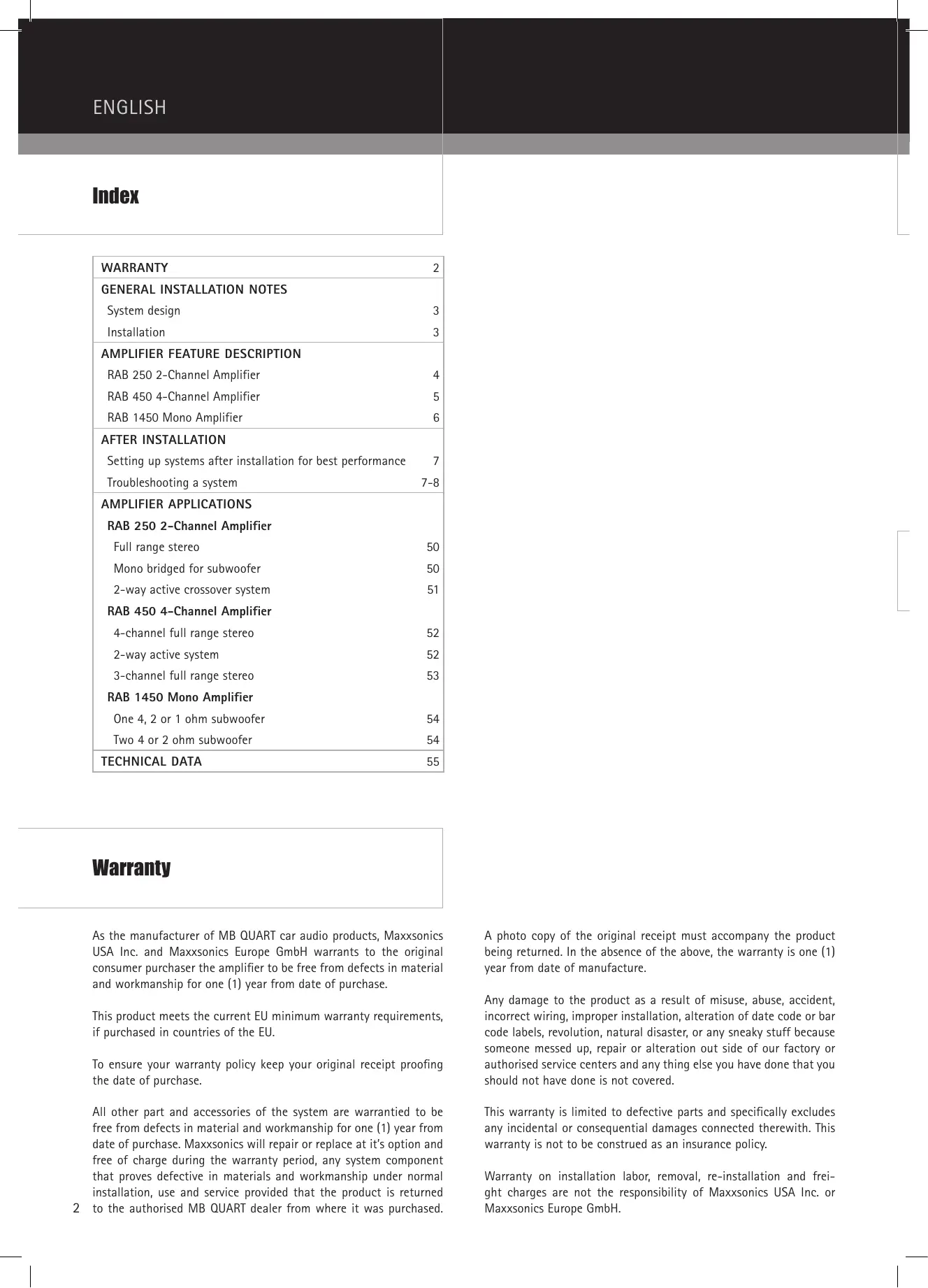
RAB 250 2-Channel Amplifier
① LED INDICATORS
- POWER: Lights up when power and remote turn on is applied.
- DIAGNOSTICS: When lit, will indicate a fault condition.
LOW PASS MODE
- Selectable in STEREO mode or MONO mode.
③ AMPLIFIER MODE
- Selects the frequency range to be amplified and routed to the loudspeakers.
- The FR (FULL RANGE) setting passes the full frequency range from the INPUT to the internal amplifiers.
- HP (HIGHPASS) will send the range of frequencies above the point set by the CROSSOVER FREQ SELECT controls.
- LP (LOW-PASS) will route those frequencies below the CROSSOVER FREQ SELECT controls to the internal amplifiers.
CROSSOVER RANGE
- The CROSSOVER RANGE selector configures the output of the crossover for X1 or X10 frequency multiplier.
- The variable pot sets the crossover frequency point for both high and low pass.
- The CROSSOVER RANGE switch is a multiplier for the variable control, for a total adjustment of 10Hz to 480Hz in 2 ranges.
6 LEVEL
- Sets the amplifier input sensitivity to match the output level of the radio/CD player.
- Note: Check your radio/CD player manual for the correct line level sensitivity and adjust the amplifier level control to match.
7 OUTPUT
- This output can drive the input of other amplifiers in a system (daisy chain).
⑧ INPUT
- LEFT and RIGHT inputs to the amplifier, from the radio/CD line level (RCA) source with a range of 0.6 volts to 6 volts.
- Use a line converter if the radio/CD player has speaker (high level) outputs only.
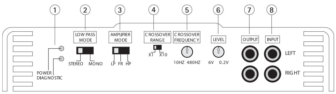
RAB 450 4-Channel Amplifier
1 LED INDICATORS
- POWER: Lights up when power and remote turn-on is applied.
- DIAGNOSTICS: When lit, will indicate a fault condition.
CH1/2 MODE
- DUPE CH3/4 routes signal as selected by the amps 3 & 4 SELECT to the 1 & 2 amplifier pair. Note that in this case, channels 1 & 2 level will be set by the LEVEL CH3/4 control only, for an exact duplication of the 3 & 4 amplifier pair signal.
- FR (FULL RANGE) passes the full frequency range from CH1/2 INPUT to the inter nal amplifiers.
- HP (HIGH PASS) will send the range of frequencies above the point set by the variable HIGH PASS control.
CH1/2 HIGH PASS
- Variable HIGH PASS filter from 50 Hz to 5 kHz.
- This control is bypassed when CH1/2 is in DUPE 3/4 or FR (FULL RANGE) selection.
CH1/2 LEVEL
- Sets CH1/2 input sensitivity to match the output level of the radio/CD player.
- Note that when the amps' CH1/2 select switch is in the DUPE CH3/4 position, the CH1/2 LEVEL control no longer affects CH1/2.
CH3/4 MODE
- MONO is selected when bridging channels 3 & 4.
- LP/BP (LOW PASS/BANDPASS) will route those frequencies above the HIGH PASS setting and below the LOW PASS setting to the internal amplifier. In this mode the HIGH PASS acts as a SUBSONIC filter.
- FR/HP (FULL RANGE/HIGH PASS) bypasses the LOW PASS setting and the frequencies reproduced are anything to above the HIGH PASS setting.
6 3et4 HIGH PASS
- This high pass filter, variable from 10Hz to 1kHz , is permanently connected to the input of the amplifier pair.
-
Since it can vary down to 10Hz , at that point it can be regarded as full range.
-
Having this per manently connected to the 3 & 4 pair, allows us to use it at any time, either as a subsonic, when set from 20Hz to 40Hz or as the lower or high pass cut off frequency control for active bandpass applications, in conjunction with the LOW PASS filter when the CH3/4 MODE switch is in the LOW PASS setting.
LOW PASS
- Continuously variable low pass filter, 50Hz to 5kHz .
- Signal routing and mode set by CH3/4 MODE and the LOW PASS setting.
CH3/4 LEVEL
- Sets CH3/4 input sensitivity to match the output level of the radio/CD player.
- Note that when the amps' CH1/2 select switch is in the DUPE CH3/4 position, the CH1/2 LEVEL control no longer affects CH1/2.
9 INPUT MODE
- In the 2CH position, all four channels are provided signal from the CH1/2 RCA Inputs.
- In the 4CH position, channels 1/2 receive input from CH1/2 RCA inputs, and channels 3/4 receive input from CH3/4 RCA inputs.
10 OUTPUT
- This output can drive the input of other amplifiers in a system (daisy chain).
- In 4CH mode: Set switch 9 to 4CH. All 4 channels are mono mixed and then fed to both line out RCAs. This provides a front/rear mono signal for constant non-faded sub bass to feed a sub amp.
- In 2CH mode: Set switch 9 to 2CH. Only CH 1&t2 are monomixed and fed to both line out RCAs.
11 INPUT
- CH1-4 inputs to the amplifier, from the radio/CD line level (RCA) source with a range of 0.2 volts to 6 volts.
- Use a line converter if the radio/CD player has speaker (high level) outputs only
- Depending on your system layout, follow the input descriptions in section "Amplifier applications" of this manual.
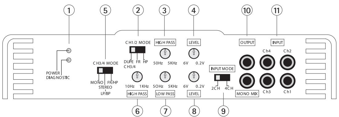
RAB 1450 Mono Amplifier
① LED INDICATORS
- POWER: Lights up when power and remote turn-on is applied.
- DIAGNOSTICS: When lit, will indicate a fault condition.
BASS REMOTE
When the MBQR-1 Bass Remote is plugged in, you can vary the bass boost from 0 dB to 9 dB via the under dash bass remote module.
3 PHASE SHIFT
Selectable PHASE of 0 degrees or 180 degree.
4 LOW PASS FILTER
- The variable LPF(LOW PASS FILTER) can be adjusted from 35Hz to 250Hz .
- Frequencies below the chosen setting will be repr oduced.
5 SUBSONIC
- The variable SUBSONIC filter can be adjusted from 10Hz to 50Hz .
- Frequencies above the chosen setting will be repruced.
BASS EQ
- The variable BASS EQ is a variable boost from 0 dB to 9 dB at fixed 45Hz
7 LEVEL
- Sets the amplifier input sensitivity to match the output level of the radio/CD player.
- Note: Check your radio/CD player manual for the cor rect line level sensitivity and adjust the amplifier level control to match.
(8) OUTPUT
- T his output can drive the input of other amplifier s in a system (daisy chain).
⑨ INPUT
- LEFT and RIGHT inputs to the amplifier, from the radio/CD line level (RCA) source with a range of 0.2 volts to 6 volts.
- Use a line converter if the radio/CD player has speaker (high level) outputs only.
Setting up systems after installation for best performance
General:
As mentioned in the "General Installation Notes" section, the system should now be powered up, and working. At this point, all crossover frequency and input selection switches should be properly set for the application, and all volume, level and equalizer controls turned to minimum.
Level control setup:
Insert a CD or cassette that you are familiar with to use as a reference, and turn the head unit volume control to about 80% of its full setting. The system sound level will of course be very low, and the following procedures will help you to match the amplifier input sensitivities properly to the head unit output signal level.
Single 2 channel amplifier systems (RAB 250):
Turn the level control up slowly, till you hear distortion, then back off a few degrees on the control.
Single 4 channel amplifier systems (RAB 450):
Turn the channel 1&t2 level control up slowly, till you hear distortion, then back off a few degrees on the control. Repeat for channel 3&t4.
2 or 3 way active systems (all):
Always start with the bass, or low frequency amplifier as a reference, by turning its control up to the point where distortion is audible, and back it off some.
Now adjust the level control for the highs or tweeter channels in a 2 way active system, to balance the highs to lows.
In a 3 way active system, match the midrange level to the bass, and then the highs to the midrange and bass. It may be necessary to perform a few iterations of the midrange and highs level control settings to achieve a satisfactory sound balance.
Crossover frequency fine tuning:
We had started off in the "General Installation Notes" section by setting crossover frequency controls to approximate positions, and now you can adjust these for best sound quality. Be careful not to stray too far from those crossover frequencies as recommended by the loudspeaker manufacturer, as it is quite possible to damage midrange and tweeters with excess power outside their nominal operating frequency ranges.
Equalizer setup:
Once all levels and crossover frequencies have been set for a pleasant sound balance, we can start equalizing the system frequency response. It is important to remember that a boost applied at any frequency, or range of frequencies, will cause severe amplifier clipping. The following comments apply to ALL equalizers and tone controls on the amplifiers, as well as those on head units and dash mount equalizers.
Use the head unit volume control to adjust the system to an intermediate level, and proceed to adjust equalizers and tone controls to personal taste. Now go back to the Level control setup above, and readjust all level controls.
Sit back and enjoy the music!
Troubleshooting a system
The key to finding the problem in a misbehaving sound system is to isolate parts of that system in a logical fashion to track down the fault.
Description of the Diagnostic system built into all MB QUART amplifiers:
The diagnostic system will shut down the amplifier, until reset by turning the head unit off, and back on. This state of affairs will be indicated by the front panel DIAGNOSTIC LED lighting up under the following conditions:
1 - A short circuit on the loudspeaker leads.
2 - An internal amplifier fault that causes a DC offset on the loudspeaker output.
Should the amplifier go into diagnostic mode, simply disconnect all RCA and speaker leads, while keeping +12 volt, power ground and remote leads connected. Now turn the amplifier back on, and if the diagnostic LED lights, the amplifier has an internal fault.
If not, plug the RCA cables back, and reset the amplifier. If it goes into diagnostic now, the fault lies in the input, either with bad cables or source unit. If the amplifier seems fine with RCA cables plugged in, connect the speakers, one at a time, and if one of the speakers or its wiring is faulty, it will activate the diagnostic system.
Amplifier heatsink overheating:
The amplifiers will shut down when the heatsink temperature reaches 80 degrees centigrade, and turn back on once the unit has cooled down below that point.
Causes of overheating:
1 - Inadequate cooling - relocate or remount to provide better natural airflow over the fins.
2 - Driving high power levels into low impedances - back off on the volume control, and/or make sure you are not loading the amplifier with less than the recommended loudspeaker impedance.
Low output power:
1 - Check that level controls have been set up properly.
2 - Make sure that the battery voltage, as measured at the amplifier's +12 volt and ground terminals, is 11 volts or more.
3 - Check all +12 volt and ground connections.
Fuses blowing:
1 - The use of loudspeaker impedances below the recommended minimums will draw more current - check.
2 - A short on the main +12 volt cable from the battery to the vehicle chassis will cause the main fuse to blow.
3 - If an amplifier fuse blows continually, with only +12 volt, ground and remote leads connected, the amplifier may be faulty.
System does not turn on:
1 - Check all fuses.
2 - Check all connections.
3 - Measure the +12 volt and remote turn on voltages at the amplifier terminals. If these are non-existent or low, take voltage measurements at fuse holders, distribution blocks, the head unit's +12 volt and remote leads to localize the problem.
Noise problems: System noise can be divided into two categories, hiss, and electrical interference.
Hiss, or white noise:
1 - High levels of white noise usually occurs when amplifier level controls are turned up too high - readjust according to the procedures in section "Setting up systems after installation for best performance"
2 - Another major problem that can cause excessive hiss, is a noisy head unit - unplug the amplifier input RCA cables, and if the hiss level reduces, the source unit is at fault.
Electrical interference:
The inside of an automobile is a very hostile electrical environment. The multitude of electrical systems, such as the ignition system, alternator, fuel pumps, air conditioners, to mention just a few, create radiated electrical fields, as well as noise on the +12 volt supply and ground. Remember to isolate the problem - first unplug amplifier input RCA cables, if the noise is still present, check the speaker leads, if not, plug the RCA's back, and investigate the source driving the amplifier, one component at a time.
A ticking or whine that changes with engine RPM:
1 - This problem could be caused by radiation pickup of RCA cables too near to a fuel pump or a distributor, for instance, - relocate cables.
2 - Check that the head unit ground is connected straight to the vehicle chassis, and does not use factory wiring for ground.
3 - Try to supply the head unit with a clean +12 volt supply directly from the battery + , instead of using a supply from the in dash wiring/fusebox.
A constant whine:
This type of noise can be more difficult to pinpoint, but is usually caused by some kind of instability, causing oscillations in the system.
1 - Check all connections, especially for good grounds.
2 - Make sure that no speaker leads are shorting to exposed metal on the vehicle chassis.
3 - RCA cables are notorious for their problematic nature, so check that these are good, in particular the shield connections.
Inhaltsverzeichnis
6. BASS EQ (Augmentation des graves)
6.BASS EQ (IOJbEM Hn3Knx YactOT)
1.CIOMOuBpyKnHacTpoKnBASSEQMOKET6bITbIOJHrT yPOBeHb Hn3KnXHaCTOTpnp45UpepeMeHHoB DnnaIa3OHe0-9dB.
7. LEVEL
1.ПивовинВ COOTBETCTBNE BXOДИУЧВТБЕЛСНБТБУСЛNTЕЛС YCINNTЕЛС CypOBHEM BIXOДA CIRHANA paДиОпrieMHNka / CD-Плеepa.
2.ПиMueHnHe:ПочTuIteВИнСТуКUIM�ЗКПУaTаUIMuBaJIeO raIIOIpNemMnHa /CD-ПиEepa OToM,ΚakOДOLJxHa 6bITb BElIyHnHa yPoBnHa cnHnHa,I npINBeDInTe B COOTBeTcBNe C3TNm yPoBeHb cnHnHa Ha BXOJe.
8. OUTPUT (INHeNbI BByXOD)
- 3T0T BbIXoJ MOxET NcONJIb3OBAbTcBdI NapeJaCu CNHaJa Ha cnJeDyUoiu yCunInTeIb (Daisy Chaining / KackaDinpoBaHne).
9. INPUT (JIINHEHbIy BXoJ)
Tikahbe HIN CBNT, KOTOpBie MeHIOCTB 3aBcHMOCTN OT YactOTbI BpaSeHn IBVaTeLa:
1-3Ty npo6JIeMy MoXHO oBbIcHHTb IpoHnKHOBeHHeM 3JIeKtPOMaHHTbIX IIOJIe B cinch-Ka6JIe YcNlNTeJI, KOToPIMeR, IPOxoJrT cINlKOM 6JIu3KO O T 6EH3OHaCocA IIIN paCnpdeJIeTeJI. IpoLoXHTb Ka6JIe IIO-DpyROMy.
2 - Поберпь, соединова Лим Климma "Землг" осовьогу ectва HeNoCpeDCTBeHNO C Stacn abTomobиЯ, И He 3a3emJIeHa Лим OHa chep3 bOpTOByO cTeb.
3 - Поньтайтусь сеоннь осовhoe устюпостбгом кабя +12В наразусь с плжкшьныm плiocom 6aрази, ВмсстTO rO,чTOБь пдкluoathь eroc nmoшь сандартей Кабльно раьоdkn/6лoka п dedoxpahtelny B uHTke риборob.
ПOTЯОнь CBNCT:
PnunHy 3TO R BnA uMBoBix NOMEX, B 3aBcHmocTb OT o6ToTeBCTBa, OppeJeNtB CLOXHee, OHaKO O6bUHO OHa CO3daETcKaKoI-JIO6O fOpMoH HeCTaBnHocTn CNTEmbl, KOTOPa PnBODIT K NOBJIeHNO HApUSeHIN B pa60Te CNTEmbl.
1 - Поверпь Се полкlio ueня, В особeHHocTи, OTHOCiteJbHo HаджHOrO 3a3eMJIeHЯ.
2 - Y6eHbC8B TOM, yTO Ka6eJIIMnHAMIKOB, INPOXdIaIne NO OTKpbIToM MeTaNIIueckoN IOBepxHOCTHe CO3JaOT KOpOTKOrO 3aMbIKAHnC lAACCn ABTomO6nJIA.
2-Cinch-ka6eIIN3BcTbI CBOeI paCIOJIOKeHHOCTbIO K BO3HMKHOBeHIO IPO6bEM, PO3OTMy IPOBepNTb IX COCTOAHNE, B YAcTHOCTN, 3KpaHpyUOJIe CoEINHeHNA.
RAB 250 2-Channel Amplifier
Full range stereo
Mono bridged for subwoofer
2-way active crossover system
4-channel full range stereo
3-channel full range stereo
| Features | RAB 250 2-CHANNEL | RAB 450 4-CHANNEL | RAB 1450 MONO |
| Output power rating Watt RMS (14.4V battery) | |||
| 4-Ohms | 50 x 2 | 50 x 4 | 200 x 1 |
| 2-Ohms | 90 x 2 | 80 x 4 | 300 x 1 |
| 1-Ohm | - | - | 450 x 1 |
| Mono bridge at 4-Ohms | 180 x 1 | 160 x 2 | - |
| Miscellaneous specifications | |||
| Slow unmute at turn on (soft start) | Yes | Yes | Yes |
| Frequency response, -3 dB | 10Hz - 30kHz | 10Hz - 30kHz | 10Hz - 250Hz |
| Damping factor | >200 | 200 | >250 |
| Signal to noise ratio (A-weighted) | >95 dB | >95 dB | >95 dB |
| THD & N | 0.05 % | 0.03 % | 0.10 % |
| Channel separation at 1 kHz | >70 dB | >70 dB | 70 dB |
| Variable input level control | 0.2 V - 6.0 V | 0.2 V - 6.0 V | 0.2 V - 6.0 V |
| Input impedance | 47 kΩ | 47 kΩ | 47 kΩ |
| Power and diagnostic LED | Yes | Yes | Yes |
| Protection: | |||
| DC, short, thermal, overload | Yes | Yes | Yes |
| Power supply, all MOSFET PWM | Yes | Yes | Yes |
| Audio output, all Bipolar | Yes | Yes | Yes |
| Crossover and switching | |||
| Input selector switch | No | Yes | No |
| Channels 1/2 | FULL/HP/LP | HP/FULL/LP | - |
| Variable high pass, 12 dB/octave | 10 Hz - 4.8 kHz | 50 Hz - 5.0 kHz | - |
| Variable Mono low pass, 24 dB/octave | - | - | 35 Hz - 250 Hz |
| Bass boost at 45 Hz | - | - | 0 - 9 dB |
| Subsonic | - | - | 10 Hz - 50 Hz |
| Channels 3/4 | - | HP/FULL/LP | - |
| Variable high pass, 12 db/octave | - | 10 Hz - 1.0 kHz | - |
| Variable Mono low pass, 24 dB/octave | - | 50 Hz - 5.0 kHz | - |
| Bass boost | - | - | - |
| Connector types | |||
| Unbalanced inputs (RCA) | Yes | Yes | Yes |
| Line output (RCA) | Selectable | Selectable | Selectable |
| Phone jack for remote control | No | No | Yes |
| Bass boost remote control Module MBQR-1 | No | No | Yes |
| Mechanical | |||
| Molded power terminal | 8-GA (10 mm²) | 8-GA (10 mm²) | 4-GA (25 mm²) |
| Molded speaker terminals | 8-GA (10 mm²) | 8-GA (10 mm²) | 8-GA (10 mm²) |
| Fuse type | ATC | ATC | ATC |
| Fuse Size | 20 Amp | 30 Amp | 2 x 25 Amp |
MAXSONICS USA, INC.
1290 Ensell Road
Lake Zurich, Illinois 60047 USA
E-Mail info@maxxsonics.com
Website www.maxxsonics.com
MAXXSONICS EUROPE GMBH
Neckarstrasse 20
74847 Obrigheim, Germany
Phone +49 (0) 62 61 - 6 38-0
FAXX +49 (0) 62 61 - 638-129
E-Mail info@mbquart.de
Website www.mbquart.de
- Warranty
- System design
- Installation
- General:
- Power and ground connections:
- Safe connection sequence:
- Power up the system:
- RAB 250 2-Channel Amplifier
- ① LED INDICATORS
- LOW PASS MODE
- ③ AMPLIFIER MODE
- CROSSOVER RANGE
- LEVEL
- OUTPUT
- ⑧ INPUT
- RAB 450 4-Channel Amplifier
- LED INDICATORS
- CH1/2 MODE
- CH1/2 HIGH PASS
- CH1/2 LEVEL
- CH3/4 MODE
- 3et4 HIGH PASS
- LOW PASS
- CH3/4 LEVEL
- INPUT MODE
- OUTPUT
- INPUT
- RAB 1450 Mono Amplifier
- BASS REMOTE
- PHASE SHIFT
- LOW PASS FILTER
- SUBSONIC
- BASS EQ
- LEVEL
- OUTPUT
- ⑨ INPUT
- Setting up systems after installation for best performance
- Level control setup:
- Single 2 channel amplifier systems (RAB 250):
- Single 4 channel amplifier systems (RAB 450):
- or 3 way active systems (all):
- Crossover frequency fine tuning:
- Equalizer setup:
- Troubleshooting a system
- Description of the Diagnostic system built into all MB QUART amplifiers:
- Amplifier heatsink overheating:
- Causes of overheating:
- Low output power:
- Fuses blowing:
- System does not turn on:
- Hiss, or white noise:
- Electrical interference:
- A ticking or whine that changes with engine RPM:
- A constant whine:
- Inhaltsverzeichnis
- BASS EQ (Augmentation des graves)
- 6.BASS EQ (IOJbEM Hn3Knx YactOT)
- LEVEL
- OUTPUT (INHeNbI BByXOD)
- INPUT (JIINHEHbIy BXoJ)
- Tikahbe HIN CBNT, KOTOpBie MeHIOCTB 3aBcHMOCTN OT YactOTbI BpaSeHn IBVaTeLa:
- ПOTЯОнь CBNCT:
- Full range stereo
- Mono bridged for subwoofer
Brand : MB QUART
Model : RAB 1450
Category : Loudspeaker