
N2U400-A - Computer ECS - Free user manual and instructions
Find the device manual for free N2U400-A ECS in PDF.

| Product Type | Desktop motherboard |
| Brand | ECS (Elitegroup Computer Systems) |
| Model | N2U400-A |
| Processor socket | Socket A (462 pins) for AMD Athlon XP, Sempron, Athlon, Duron |
| Front Side Bus (FSB) | 400/333/266/200 MHz |
| Chipset | NVIDIA nForce2 Ultra 400 (Northbridge) + nForce MCP (Southbridge) |
| RAM | 3 slots DDR SDRAM 184-pin, up to 3 GB (PC1600/2100/2700) or 2 GB (PC3200), dual channel |
| Graphics slot | 1 AGP 8x slot (1.5 V only) |
| Expansion slots | 5 PCI 32-bit slots |
| Storage | 2 IDE connectors (4 devices), 1 floppy drive, Ultra DMA 33/66/100/133 |
| Audio | AC'97 2.2 codec, S/PDIF input/output, 6-channel audio |
| Network | 10/100 Mbps Ethernet controller (VT6103) |
| USB ports | 4 USB 2.0 ports |
| I/O ports | 2 PS/2 (mouse + keyboard), 1 serial, 1 parallel, 1 LAN, audio jacks (mic, line-in, line-out) |
| BIOS | Award BIOS, advanced configuration, power management |
| Dimensions (approx.) | 305 x 244 mm (standard ATX) |
| Weight (approx.) | 0.5 kg |
| Power | 20-pin ATX connector |
| Key features | Support for AMD Socket A processors, dual-channel memory, AGP 8x, 6-channel audio, integrated network |
| Care and cleaning | Dust regularly with compressed air, avoid humidity, handle with care (electrostatic discharge) |
| Safety | Use an anti-static wrist strap when handling, disconnect power before any intervention |
| Spare parts and repairability | CMOS battery (CR2032), electrolytic capacitors, connectors; repair possible by a technician |
| General information | Desktop motherboard, Class B (Canada), manual available in PDF |
Frequently Asked Questions - N2U400-A ECS
User questions about N2U400-A ECS
0 question about this device. Answer the ones you know or ask your own.
Ask a new question about this device
Download the instructions for your Computer in PDF format for free! Find your manual N2U400-A - ECS and take your electronic device back in hand. On this page are published all the documents necessary for the use of your device. N2U400-A by ECS.
USER MANUAL N2U400-A ECS
This publication, including all photographs, illustrations and software, is protected under international copyright laws, with all rights reserved. Neither this manual, nor any of the material contained herein, may be reproduced without written consent of the author.
Version 1.0d
Disclaimer
The information in this document is subject to change without notice. The manufacturer makes no representations or warranties with respect to the contents hereof and specifically disclaims any implied warranties of merchantability or fitness for any particular purpose. The manufacturer reserves the right to revise this publication and to make changes from time to time in the content hereof without obligation of the manufacturer to notify any person of such revision or changes.
Trademark Recognition
Microsoft, MS-DOS and Windows are registered trademarks of Microsoft Corp.
nVIDIA is a registered trademark of nVIDIA Corporation.
AMD, Athlon, and Duron are registered trademarks of AMD Corporation.
Other product names used in this manual are the properties of their respective owners and are acknowledged.
Federal Communications Commission (FCC)
This equipment has been tested and found to comply with the limits for a Class B digital device, pursuant to Part 15 of the FCC Rules. These limits are designed to provide reasonable protection against harmful interference in a residential installation. This equipment generates, uses, and can radiate radio frequency energy and, if not installed and used in accordance with the instructions, may cause harmful interference to radio communications. However, there is no guarantee that interference will not occur in a particular installation. If this equipment does cause harmful interference to radio or television reception, which can be determined by turning the equipment off and on, the user is encouraged to try to correct the interference by one or more of the following measures:
Reorient or relocate the receiving antenna.
Increase the separation between the equipment and the receiver.
- Connect the equipment onto an outlet on a circuit different from that to which the receiver is connected.
- Consult the dealer or an experienced radio/TV technician for help.
Shielded interconnect cables and a shielded AC power cable must be employed with this equipment to ensure compliance with the pertinent RF emission limits governing this device. Changes or modifications not expressly approved by the system's manufacturer could void the user's authority to operate the equipment.
Declaration of Conformity
This device complies with part 15 of the FCC rules. Operation is subject to the following conditions:
This device may not cause harmful interference, and
- This device must accept any interference received, including interference that may cause undesired operation.
Canadian Department of Communications
This class B digital apparatus meets all requirements of the Canadian Interference-causing Equipment Regulations.
The manual consists of the following:
Chapter 1
Introducing the Motherboard
Describes features of the motherboard, and provides a shipping checklist.
Go to page 1
Chapter 2
Installing the Motherboard
Describes installation of motherboard components.
Go to page 6
Chapter 3
Using BIOS
Provides information on using the BIOS Setup Utility.
Go to page 24
Chapter 4
Using the Motherboard Software
Describes the motherboard software.
Go to page 40
Features Translations
\section*{Caracteristiques}
Features Translations iii
CHAPTER 1
Introducing the Motherboard 1
Introduction 1
Features 2
Motherboard Components 4
CHAPTER 2
6
Safety Precautions. 6
Choosing a Computer Case 6
Quick Guide. 6
Installing the Motherboard in a Case 7
Checking Jumper Settings 7
Setting Jumpers 7
Checking Jumper Settings 8
Jumper Settings 8
Connecting Case Components. 9
Front Panel Connector 11
Installing Hardware 12
Installing the Processor. 12
Installing Memory Modules 15
Installing a Hard Disk Drive/CD-ROM 17
Installing a Floppy Diskette Drive 18
Installing Add-on Cards. 19
Connecting Optional Devices 20
Connecting I/O Devices 23
External Connector Color Coding 23
CHAPTER 3 24
UsingBIOS 24
About the Setup Utility 24
The Standard Configuration 24
Entering the Setup Utility 25
Updating the BIOS 25
UsingBIOS. 26
Standard CMOS Features 27
AdvancedBIOSFeatures 29
Advanced Chipset Features 31
Integrated Peripherals 33
Power Management Setup. 35
PNP/PCI Configurations. 36
PC Health Status 37
Load Fail-Safe Defaults. 38
Load Optimized Defaults. 38
Set Supervisor/User Password 38
Save & Exit Setup 39
Exit Without Saving 39
CHAPTER 4 40
Using the Motherboard Software 40
About the Software CD-ROM 40
Auto-installing under Windows 98/ME/2000/XP 40
Running Setup 41
Manual Installation 43
Utility Software Reference 43
Chapter 1
Introducing the Motherboard
Introduction
Thank you for choosing the N2U400-A motherboard. The N2U400-A is designed to fit the advanced AMD processors in the 462-pin package, supporting socket 462 AMD Athlon XP / Sempron / Athlon / Duron processors. Based on NVIDIA® nForce™ 2 ULTRA-400 Northbridge and NVIDIA® nForce™ MCP Southbridge chipsets. This ATX form factor motherboard with a measurement of 305mm× 244mm is intended to give customers a high performance and utmost intelligent PC solution.
The nForce2 ULTRA-400 is designed for AMD Athlon XP / Sempron / Athlon / Duron processors and delivers 128-bit DDR 400 memory controller with Dual DDR. It works together with nForce2 MCP media communication processor providing Universal Serial Bus 2.0 Host Controllers and Audio Controller with AC 97 interface. It also features AGP3.0 8X host interface, HyperTransport1 interface and support Front Side Bus (FSB) up to 400/333/266 MHz.
The N2U400-A motherboard provides an advanced set of I/O ports, such as dual channel IDE interfaces, a floppy controller, one high-speed serial port, an EPP/ECP capable bi-directional parallel port connector, four USB (Universal Serial Bus) connectors, a PS/2 keyboard connector, mouse connector and audio jacks for microphone, line-in and line-out. One AGP slot and five PCI local bus slots provide expandability for add-on peripheral cards.
Features
| Processor | The motherboard uses a 462-pin Socket that has the following features: • Supports 400/333/266/200 MHz Front Side Bus (FSB) • Accommodates AMD Athlon XP/Sempron/Athlon/Duron CPU • 200/166/133 MHz DDR (Double Data Rate) transfer on Athlon XP/Sempron/Athlon/Duron CPU address and data buses |
| Chipset | The motherboard integrates the NVIDIA® nForce™ 2 Ultra-400 Northbridge and NVIDIA® nForce™ MCP Southbridge chipsets. A few of the chipset's advanced features are: • High speed 800MB/sec HyperTransportTM interface to the MCP Southbridge • 200/166/133 MHz DDR (Double Data Rate) transfer on Athlon XP/Sempron/Athlon/Duron CPU address and data buses • 8x AGP 3.0 interface at 533 MHz • PCI 2.2 compatible interface supporting 5 PCI slots • Dual fast ATA-133 IDE controllers • 10/100BaseT • USB 2.0 Enhanced Host Controller Interface (EHCI)/Open Host Controller Interface (OHCI) controller • Dual System Management Bus (SMBus) controllers • AC'97 interface supporting up to two concurrent codes |
| Memory | The motherboard supports three 184-pin DDR SDRAM DIMM slots, which accommodates 3GB for PC1600/2100/2700 (2GB for PC3200). It also features dual-channel mode of 128-bit data transfer rate. |
| Graphics | The motherboard includes an AGP slot that provides eight times the bandwidth of the original AGP specification. The AGP 3.0 (8x AGP) offers a significant increase in performance along with feature enhancements to AGP2.0. This interface represents the natural evolution from the existing AGP to meet the ever-increasing demands placed on the graphic interfaces within the workstation and desktop environments. |
| Audio | The AC' 97 Audio codec is compliant with the AC 97 2.2 specification that meets the PC2001 requirements and supports S/PDIF Out. It also has a built-in buffer and internal PLL. Features include support for analog switch for rear-out (share), the line-in jack (share), center/bass (share), and MIC jack to output 6 channels audio. |
| Expansion Options | The motherboard comes with the following expansion options: • Five 32-bit PCI slots • One AGP slot (supports 1.5V AGP Interface only) • Two IDE connectors which support four IDE channels and a floppy disk drive interface The motherboard supports Ultra DMA bus mastering with transfer rates of 33/66/100/133 MB/sec. |
| Onboard LAN (optional) | The VT6103L is a Physical Layer device for Ethernet 10BASE-T and 100BASE-TX using category 5 Unshielded, Type 1 Shielded, and Fiber Optic cables. • Dual Speed – 100/10 Mbps • Half And Full Duplex • Meet All Applicable IEEE 802.3, 10Base-T and 100Base-Tx Standards • Adaptive Equalizer |
| Integrated I/O | The motherboard has a full set of I/O ports and connectors: • Two PS/2 ports for mouse and keyboard • One serial port • One parallel port • Four USB ports • One LAN port • Audio jacks for microphone, line-in and line-out |
| BIOS Firmware | This motherboard uses Award BIOS that enables users to configure many system features including the following: • Power management • Wake-up alarms • CPU parameters • CPU and memory timing The firmware can also be used to set parameters for different processor clock speeds. |

Some hardware specifications and software items are subject to change without prior notice.
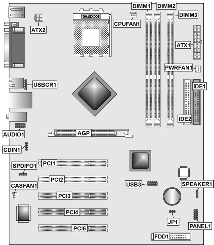
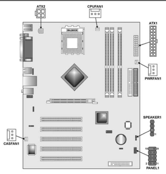
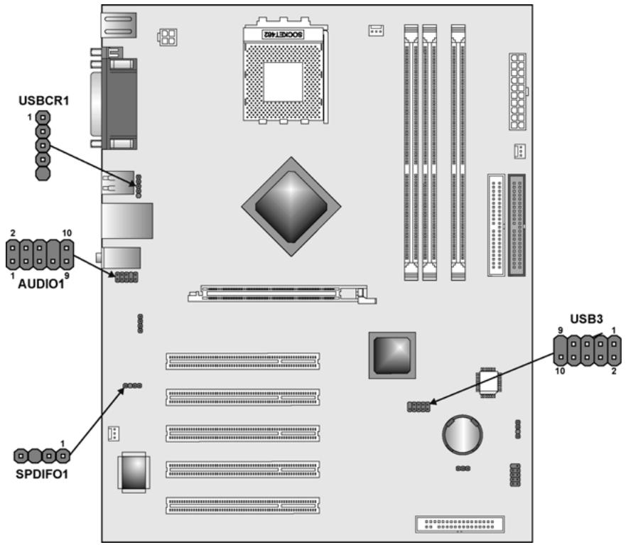
Motherboard Components
Table of Motherboard Components
| Label | Component |
| AGP | Accelerated Graphics Port (supports 1.5V AGP card only) |
| ATX1 | Standard 20-pin ATX power connector |
| ATX2 | ATX 12V Power Connector |
| AUDIO1 | Front audio connector |
| CASFAN1 | Case fan connector |
| CDIN1 | Primary CD-in connector |
| CPU SOCKET | Socket A for AMD CPU |
| CPUFAN1 | Cooling fan for CPU |
| DIMM1~ DIMM3 | Three 184-pin DDR SDRAM |
| FDD1 | Floppy disk drive connector |
| IDE 1 | Primary IDE channel |
| IDE 2 | Secondary IDE channel |
| JP1 | Clear CMOS jumper |
| PANEL1 | Connector for case front panel switches and LED indicators |
| PCI1 ~ PCI5 | Five 32-bit add-on card slots |
| PANEL1 | Panel connector for case switches and LEDs |
| PWRFAN1 | Power fan connector |
| SPDIFO1 | SPDIF out header (optional) |
| SPEAKER1 | Speaker connector |
| USB3 | Connector for front panel USB ports |
| USBCR1 | USB Card reader connector |
This concludes Chapter 1. The next chapter explains how to install the motherboard.
Safety Precautions
Follow these safety precautions when installing the motherboard:
- Wear a grounding strap attached to a grounded device to avoid damage from static electricity.
- Discharge static electricity by touching the metal case of a safely grounded object before working on the motherboard.
- Leave components in the static-proof bags they came in.
- Hold all circuit boards by the edges. Do not bend circuit boards.
Choosing a Computer Case
There are many types of computer cases on the market. The motherboard complies with the specifications for the ATX system case. Some features on the motherboard are implemented by cabling connectors on the motherboard to indicators and switches on the system case. Ensure that your case supports all the features required. The motherboard can support one or two floppy diskette drives and four enhanced IDE drives. Ensure that your case has sufficient power and space for all the drives that you intend to install.
Most cases have a choice of I/O templates in the rear panel. Make sure that the I/O template in the case matches the I/O ports installed on the rear edge of the motherboard.
This motherboard has an ATX form factor of 305 × 244 ~mm . Choose a case that accommodates this form factor.
Quick Guide
This Quick Guide suggests the steps you can take to assemble your system with the motherboards.
The following table provides a reference for installing specific components:
Locating Motherboard Components Go to page 4
Installing the Motherboard in a Case Go to page 7
Setting Jumpers Go to page 7
Installing Case Components Go to page 9
Installing the CPU Go to page 12
Installing Memory Go to page 15
Installing a HDD and CD-ROM Drive Go to page 17
Installing an FDD Go to page 18
Installing Add-on Cards Go to page 19
Connecting Options Go to page 20
Connecting Peripheral (I/O) Devices Go to page 23
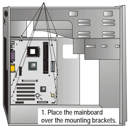
Installing the Motherboard in a Case
Refer to the following illustration and instructions for installing the motherboard in a case:
This illustration shows an example of a motherboard being installed in a tower-type case:
Note: Do not overtighten the screws as this can stress the motherboard.
Most system cases have mounting brackets installed in the case, which correspond to the holes in the motherboard. Place the motherboard over the mounting brackets and secure the motherboard onto the mounting brackets with screws.
- Secure the mainboard with screws where appropriate.
Ensure that your case has an I/O template that supports the I/O ports and expansion slots on your motherboard.
Checking Jumper Settings
This section explains how to set jumpers for correct configuration of the motherboard.
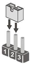
Setting Jumpers
Use the motherboard jumpers to set system configuration options. Jumpers with more than one pin are numbered. When setting the jumpers, ensure that the jumper caps are placed on the correct pins.
The illustrations below show a 2-pin jumper. When the jumper cap is placed on both pins, the jumper is SHORT. If you remove the jumper cap, or place the jumper cap on just one pin, the jumper is OPEN.
This illustration shows a 3-pin jumper. Pins 1 and 2 are SHORT.
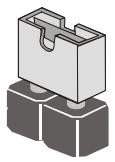
Short
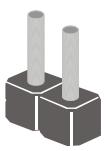
Open
Checking Jumper Settings
The following illustration shows the location of the motherboard jumpers. Pin 1 is labeled.
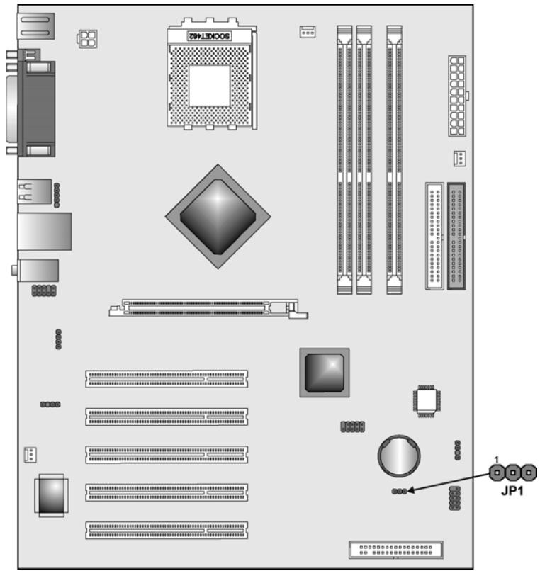
Jumper Settings
| Jumper | Type | Description | Setting (default) |
| JP1 | 3-pin | Clear CMOS | 1-2: Normal 2-3: Clear CMOS Before clearing CMOS, make sure to turn off the system. JP1 1 |
Connecting Case Components
After you have installed the motherboard into a case, you can begin connecting the motherboard components. Refer to the following:
- Connect the Pentium 4 auxiliary power supply connector to ATX2.
- Connect the standard power supply connector to ATX1.
- Connect the CPU cooling fan cable to CPUFAN1.
- Connect the case cooling fan connector to CASFAN1.
- Connect the power cooling fan connector to PwRFAN1.
- Connect the case speaker cable to SPEAKER1.
- Connect the case switches and indicator to PANEL1.
ATX2:ATX 12V Power Connector
| Pin | Signal Name |
| 1 | Ground |
| 2 | Ground |
| 3 | +12V |
| 4 | +12V |
ATX1: ATX 20-pin Power Connector
| Pin | Signal Name | Pin | Signal Name |
| 1 | +3.3V | 11 | +3.3V |
| 2 | +3.3V | 12 | -12V |
| 3 | Ground | 13 | Ground |
| 4 | +5V | 14 | PS ON# |
| 5 | Ground | 15 | Ground |
| 6 | +5V | 16 | Ground |
| 7 | Ground | 17 | Ground |
| 8 | PWRGD | 18 | -5V |
| 9 | +5VSB | 19 | +5V |
| 10 | +12V | 20 | +5V |
CPUFAN1/CASFAN1/PWRFAN1: FAN Power Connectors
| Pin | Signal Name | Function |
| 1 | GND | System Ground |
| 2 | +12V | Power +12V |
| 3 | Sense | Sensor |
SPEAKER1: Internal speaker
| Pin | Signal Name |
| 1 | Signal |
| 2 | Key |
| 3 | Ground |
| 4 | VCC |
Front Panel Connector
The front panel connector (PANEL1) provides a standard set of switch and LED connectors commonly found on ATX or micro-ATX cases. Refer to the table below for information:
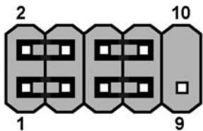
PANEL1
| Pin | Signal | Function | Pin | Signal | Function |
| 1 | HD_LED_P | Hard disk LED (positive) | 2 | FP PWR/SLP | MSG LED [dual color or single color (+)] |
| 3 | HD_LED_N | Hard disk active LED (negative) | 4 | FP PWR/SLP | MSG LED [dual color or single color (-)] |
| 5 | RST_SW_N | Reset Switch | 6 | PWR_SW_P | Power Switch |
| 7 | RST_SW_P | Reset Switch | 8 | PWR_SW_N | Power Switch |
| 9 | RSVD | Reserved | 10 | NC | No pin |
Hard Drive Activity LED
Connecting pins 1 and 3 to a front panel mounted LED provides visual indication that data is being read from or written to the hard drive. For the LED to function properly, an IDE drive should be connected to the onboard IDE interface. The LED will also show activity for devices connected to the SCSI (hard drive activity LED) connector.
Power / Sleep / Message Waiting LED
Connecting pins 2 and 4 to a single- or dual-color, front panel mounted LED provides power on/off, sleep, and message waiting indication.
Reset Switch
Supporting the reset function requires connecting pins 5 and 7 to a momentary-contact switch that is normally open. When the switch is closed, the board resets and runs POST.
Power Switch
Supporting the power on/off function requires connecting pins 6 and 8 to a momentary-contact switch that is normally open. The switch should maintain contact for at least 50~ms to signal the power supply to switch on or off. The time requirement is due to internal debounce circuitry. After receiving a power on/off signal, at least two seconds elapses before the power supply recognizes another on/off signal.
Installing Hardware
Installing the Processor
Caution: When installing a CPU heatsink and cooling fan make sure that you DO NOT scratch the motherboard or any of the surface-mount resistors with the clip of the cooling fan. If the clip of the cooling fan scrapes across the motherboard, you may cause serious damage to the motherboard or its components.
On most motherboards, there are small surface-mount resistors near the processor socket, which may be damaged if the cooling fan is carelessly installed.
Avoid using cooling fans with sharp edges on the fan casing and the clips. Also, install the cooling fan in a well-lit work area so that you can clearly see the motherboard and processor socket.
Before installing the Processor
This motherboard automatically determines the CPU clock frequency and system bus frequency for the processor. You may be able to change these settings by making changes to jumpers on the motherboard, or changing the settings in the system Setup Utility. We strongly recommend that you do not overclock processors or other components to run faster than their rated speed.
Warning: Overclocking components can adversely affect the reliability of the system and introduce errors into your system. Overclocking can permanently damage the motherboard by generating excess heat in components that are run beyond the rated limits.
This motherboard has a Socket 462 processor socket. When choosing a processor, consider the performance requirements of the system. Performance is based on the processor design, the clock speed and system bus frequency of the processor, and the quantity of internal cache memory and external cache memory.
CPU Installation Procedure
This motherboard is built with Socket 462 processor socket. When choosing a processor, consider the performance requirements of the system. The following illustration shows CPU installation components:
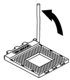
Step 1
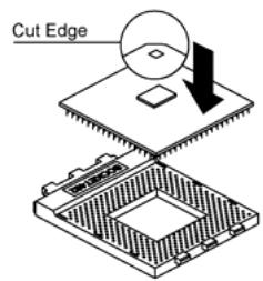
Step 2
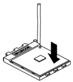
Step 3
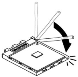
Step 4
Orient the CPU so the odd corner matches the odd corner of the socket. With the lever in an upright position, gently place the CPU on the socket; make sure that all pins line up with the socket holes. When pins are aligned, the CPU should seat itself in the socket. Apply very light pressure to ensure the CPU is evenly seated. Push the lever down and ensure it latches firmly.
Note: Remember to apply thermal grease on top of the CPU.
Installing CPU Fan and Fan Connector
CPU fan and heatsink installation procedures may vary with the type of CPU fan/heatsink supplied. The form and size of fan/heatsink may also vary. Without an effective cooling fan, the CPU can overheat and cause damage to both CPU and the motherboard.
| 1. Lower the CPU cooling fan/heatsink assembly onto the CPU. | ||
| 2. Secure the two retention clips on either side of the fan/heatsink unit onto the Socket 462 base. | ||
| 3. Connect the CPU Cooling Fan power cable connector to the CPUFAN connector. |
Installing Memory Modules
This motherboard accommodates three 184-pin 2.5V unbuffered non-ECC Double Data Rate (DDR) SDRAM memory modules.
This motherboard can support DDR266/DDR333/DDR400 memory modules and allow up to 6.4 GB/s data transfer rate. Utilizing the dual-channel DDR memory architecture, this motherboard provides a solution which doubles the system memory bandwidth of your system memory and boost the system performance. Please refer to page 16 for suggested dual-channel DDR combinations.
You must install at least one module in any of the three slots. Each module can be installed with 128 MB to 1 GB of memory. Total capacity is 3GB.

Do not remove any memory module from its antistatic packaging until you are ready to install it on the motherboard. Handle the modules only by their edges. Do not touch the components or metal parts. Always wear a grounding strap when you handle the modules.
Refer to the following to install the memory modules.
- This motherboard supports unbuffered DDR SDRAM only. Do not attempt to insert any other type of DDR SDRAM into the slots.
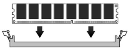
- Push the latches on each side of the DIMM slot down.
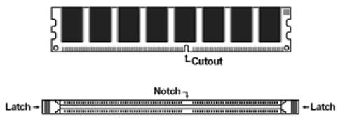
- Align the memory module with the slot. The DIMM slots are keyed with notches and the DIMMs are keyed with cutouts so that they can only be installed correctly.
- Check that the cutouts on the DIMM module edge connector match the notches in the DIMM slot.
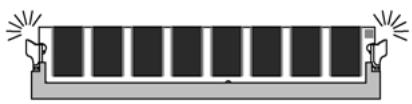
- Install the DIMM module into the slot and press it firmly down until it seats correctly. The slot latches are levered upwards and latch on to the edges of the DIMM.
- Install any remaining DIMM modules.
Table A: Recommended dual-channel DDR configurations
| DIMM1 | DIMM2 | DIMM3 | Dual Channel |
| ✓ | ✓ | ✓ | |
| ✓ | ✓ | ✓ | |
| ✓ | ✓ | ✓ | ✓ |
Note: When using dual channel mode, install only similar (same density, DRAM technology and DRAM bus width) module for each channel.
Table B: CPU FSB and Memory Frequency
Table C: DDR (memory module) QVL (Qualified Vendor List)
| CPU FSB | DDR Module support | DDR Type |
| 400 MHz | DDR 400/333/266 | PC3200/PC2700/PC2100 |
| 333 MHz | DDR 333/266 | PC2700/PC2100 |
| 266 MHz | DDR 266 | PC2100 |
The following DDR400 memory modules have been tested and qualified for use with this motherboard.
| Size | Vendor | Brand | Model Number |
| 128MB | SAMSUNG | SAMSUNG | K4H280838D-TCC4 |
| NANYA | NANYA | NT5DS16M16BT-5 | |
| Infineon | Infineon | HYB25D256160BT-5 | |
| NANYA | NANYA | NT5DS16M16BT-5T | |
| 256MB | SAMSUNG | SAMSUNG | K4H560838D-TCC4 |
| NANYA | NANYA | NT5DS32M8BT-6K | |
| Micron | Micron | MT46V16M8-5 ESB | |
| Infineon | Infineon | HYB25D256800BT-5 | |
| Micron | Micron | MT46V32M8-5BC | |
| NANYA | NANYA | NT5DS32M8BT-5T | |
| Apacer | SAMSUNG | K4H560838D-TCC4 | |
| 512MB | SAMSUNG | SAMSUNG | K4H560838D-TCC4 |
| NANYA | NANYA | NT5D32M8BT-5 | |
| Micron | Micron | MT46V32M8-5BC | |
| NANYA | NANYA | NT5DS32M8BT-5T |
Installing a Hard Disk Drive/CD-ROM
This section describes how to install IDE devices such as a hard disk drive and a CD-ROM drive.
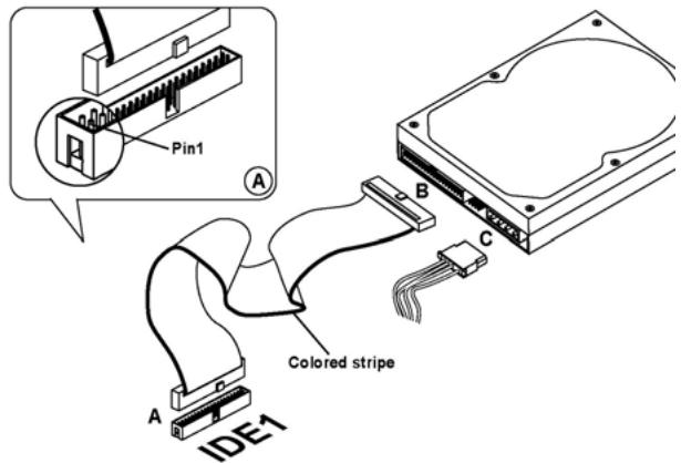
Your motherboard has a primary and secondary IDE channel interface (IDE1 and IDE2). An IDE ribbon cable supporting two IDE devices is bundled with the motherboard.
If you want to install more than two IDE devices, get a second IDE cable and you can add two more devices to the secondary IDE channel.
IDE1: Primary IDE Connector
The first hard drive should always be connected to IDE1.
IDE2: Secondary IDE
The second drive on this controller must be set to slave mode. The configuration is the same as IDE1.
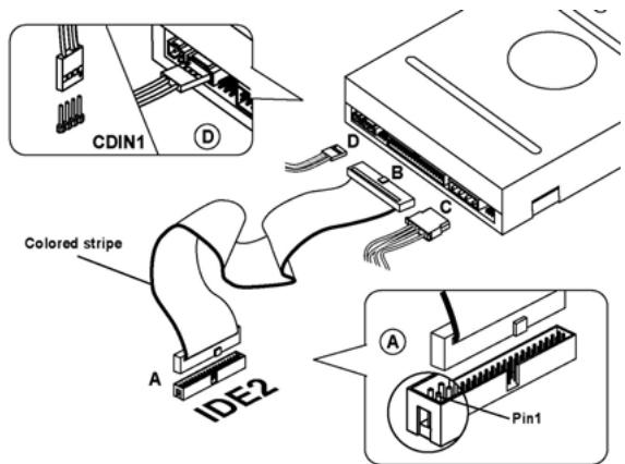

You must orient the cable connector so that the pin 1 (color) edge of the cable corresponds to the pin 1 of the I/O port connector.
IDE devices have jumpers or switches that are used to set the IDE device as MASTER or SLAVE. Refer to the IDE device user's manual. When installing two IDE devices on one cable, ensure that one device is set to MASTER and the other device is set to SLAVE. The documentation of your IDE device explains how to do this.
About UltraDMA
This motherboard supports UltraDMA 66/100/133. UDMA is a technology that accelerates the performance of devices in the IDE channel. To maximize performance, install IDE devices that support UDMA and use 80-pin IDE cables that support UDMA 66/100/133.
Installing a Floppy Diskette Drive
The motherboard has a floppy diskette drive (FDD) interface and ships with a diskette drive ribbon cable that supports one or two floppy diskette drives. You can install a 5.25-inch drive and a 3.5-inch drive with various capacities. The floppy diskette drive cable has one type of connector for a 5.25-inch drive and another type of connector for a 3.5-inch drive.
FDD1: Floppy Disk Connector
This connector supports the provided floppy drive ribbon cable. After connecting the single end to the onboard floppy connector, connect the remaining plugs on the other end to the floppy drives correspondingly.
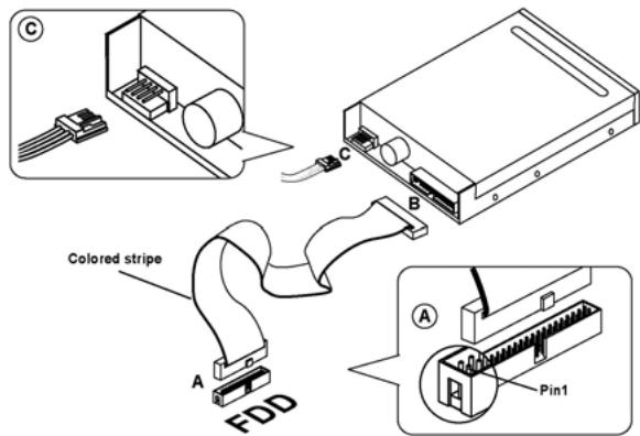

You must orient the cable connector so that the pin 1 (color) edge of the cable corresponds to the pin 1 of the I/O port connector.
Installing Add-on Cards
The slots in this motherboard are designed to hold expansion cards and connect them to the system bus. Expansion slots are a means of adding or enhancing the motherboard's features and capabilities. With these efficient facilities, you can increase the motherboard's capabilities by adding hardware which performs tasks that are not part of the basic system.
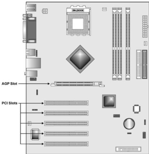
PCI Slots
PCI slots are used to install expansion cards that have the 32-bit PCI interface.
AGP Slot
The AGP slot is used to install 3D graphics adapter that supports the 8x AGP card which is also backward compatible with 4x AGP card. The slot is keyed to support only the latest 1.5-volt AGP cards.
Note: Before installing an add-on card, check the documentation for the card carefully. If the card is not Plug and Play, you may have to manually configure the card before installation.
Follow these instructions to install an add-on card:
-
Remove a blanking plate from the system case corresponding to the slot you are going to use.
-
Install the edge connector of the add-on card into the expansion slot. Ensure that the edge connector is correctly seated in the slot.
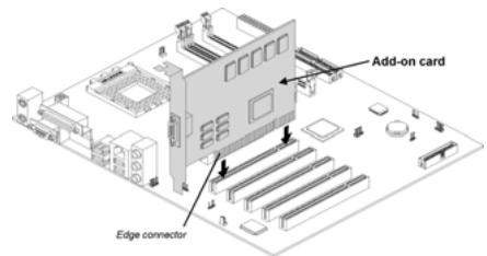
- Secure the metal bracket of the card to the system case with a screw.
Note: For some add-on cards, for example graphics adapters and network adapters, you have to install drivers and software before you can begin using the add-on card.
Connecting Optional Devices
Refer to the following for information on connecting the motherboard's optional devices:
AUDIO1: Front Panel Audio header
This header allows the user to install auxiliary front-oriented microphone and line-out ports for easier access.
| Pin | Signal Name | Function |
| 1 | AUD_MIC | Front Panel Microphone input signal |
| 2 | AUD_GND | Ground used by Analog Audio Circuits |
| 3 | AUD_MIC_BIAS | Microphone Power |
| 4 | AUD_VCC | Filtered +5 V used by Analog Audio Circuits |
| 5 | AUD_FPOUT_R | Right Channel Audio signal to Front Panel |
| 6 | AUD_RET_R | Right Channel Audio signal to Return from Front Panel |
| 7 | HP_ON | Reserved for future use to control Head- phone Amplifier |
| 8 | KEY | No Pin |
| 9 | AUD_FPOUT_L | Left Channel Audio signal to Front Panel |
| 10 | AUD_RET_L | Left Channel Audio signal Return from Front Panel |
USB3: Front panel USB connectors
The motherboard has four USB ports installed on the rear edge I/O port array. Additionally, some computer cases have USB ports at the front of the case. If you have this kind of case, use auxiliary USB connector USB3 to connect the front-mounted ports to the motherboard.
| Pin | Signal Name | Function |
| 1 | VREG_FP_USBPWR0 | Front Panel USB Power |
| 2 | VREG_FP_USBPWR0 | Front Panel USB Power |
| 3 | USB_FP_P0- | USB Port 0 Negative Signal |
| 4 | USB_FP_P1- | USB Port 1 Negative Signal |
| 5 | USB_FP_P0+ | USB Port 0 Positive Signal |
| 6 | USB_FP_P1+ | USB Port 1 Positive Signal |
| 7 | GND | Ground |
| 8 | GND | Ground |
| 9 | KEY | No pin |
| 10 | Not assigned | Not assigned |
Note: Please make sure that the USB cable has the same pin assignment as indicated above. A different pin assignment may cause damage or system hang-up.
USBCR1: USB Card Reader connector
This connector is for connecting internal USB card reader. You can use a card reader to read or transfer files and digital images to your computer.
| Pin | Signal Name | Function |
| 1 | USBVCC2 | +5V dual |
| 2 | USB2- | Data signal port 2- |
| 3 | USB2+ | Data signal port 2+ |
| 4 | GND | Ground |
| 5 | Key | No pin |
Note: The USBCR1 is shared with one of the USB ports of the I/O back panel. See "Connecting I/O Devices" for more information.

Please check the pin assignment of the cable and the USB header on the motherboard. Make sure the pin assignment will match before plugging in. Any incorrect usage may cause unexpected damage to the system.
SPDIFO1: SPDIF out header (optional)
This is an optional header that provides an S/PDIF (Sony/Philips Digital Interface) output to digital multimedia device through optical fiber or coaxial connector.
| Pin | Signal Name | Function |
| 1 | SPDIF | SPDIF digital output |
| 2 | +5VA | 5V analog power |
| 3 | NC | Not connected |
| 4 | GND | Ground |
Connecting I/O Devices
The backplane of the motherboard has the following I/O ports:
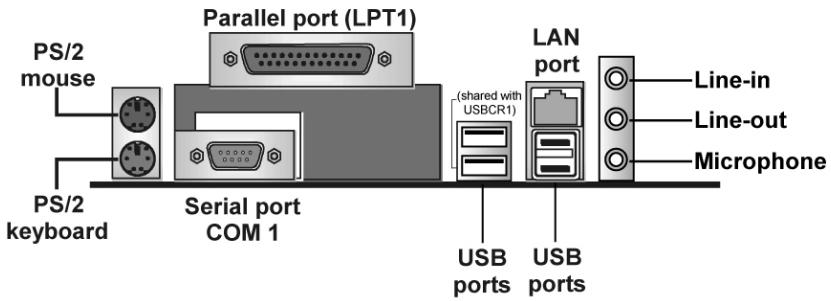
PS/2 Mouse
Use the upper PS/2 port to connect a PS/2 pointing device.
PS/2 Keyboard
Use the lower PS/2 port to connect a PS/2 keyboard.
LPT1
Use LPT1 to connect printers or other parallel communications devices.
COM1
Use the COM ports to connect serial devices such as mice or fax/modems. COM1 is identified by the system as COM1/3.
Audio Ports
Use the three audio ports to connect audio devices. The first jack is for stereo line-in signal. The second jack is for stereo line-out signal. The third jack is for microphone.
LAN Port
Connect an RJ-45 jack to the LAN port to connect your computer to the Network.
(optional)
Use the USB ports to connect USB devices.
External Connector Color Coding
Many connectors now use standard colors as shown in the table below.
| Connector | Color |
| Audio line-in | Light blue |
| Audio line-out | Light Green |
| Microphone | Pink |
| Parallel | Burgundy |
| PS/2-compatible keyboard | Purple |
| PS/2-compatible mouse | Green |
| Serial | Teal or Turquoise |
| USB | Black |
| LAN | Black |
This concludes Chapter 2. The next chapter covers the BIOS.
About the Setup Utility
The computer uses the latest Award BIOS with support for Windows Plug and Play. The CMOS chip on the motherboard contains the ROM setup instructions for configuring the motherboard BIOS.
The BIOS (Basic Input and Output System) Setup Utility displays the system's configuration status and provides you with options to set system parameters. The parameters are stored in battery-backed-up CMOS RAM that saves this information when the power is turned off. When the system is turned back on, the system is configured with the values you stored in CMOS.
The BIOS Setup Utility enables you to configure:
- Hard drives, diskette drives, and peripherals
Video display type and display options - Password protection from unauthorized use
Power management features
The settings made in the Setup Utility affect how the computer performs. Before using the Setup Utility, ensure that you understand the Setup Utility options.
This chapter provides explanations for Setup Utility options.
The Standard Configuration
A standard configuration has already been set in the Setup Utility. However, we recommend that you read this chapter in case you need to make any changes in the future.
This Setup Utility should be used:
- when changing the system configuration
- when a configuration error is detected and you are prompted to make changes to the Setup Utility
- when trying to resolve IRQ conflicts
- when making changes to the Power Management configuration
- when changing the password or making other changes to the Security Setup
Entering the Setup Utility
When you power on the system, BIOS enters the Power-On Self Test (POST) routines. POST is a series of built-in diagnostics performed by the BIOS. After the POST routines are completed, the following message appears:
Press DEL to enter SETUP
Pressing the delete key accesses the BIOS Setup Utility:
| Phoenix - AwardBIOS CMOS Setup Utility | |
| Standard CMOS Features | Load Fail-Safe Defaults |
| Advanced BIOS Features | Load Optimized Defaults |
| Advanced Chipset Features | Set Supervisor Password |
| Integrated Peripherals | Set User Password |
| Power Management Setup | Save & Exit Setup |
| PnP/PCI Configurations | Exit Without Saving |
| PC Health Status | |
| Esc: Quit F9: Menu in BIOS ↑ ↓ → : Select Item F10: Save & Exit Setup | |
| Virus Protection, Boot Sequence... | |
BIOS Navigation Keys
The BIOS navigation keys are listed below:
| Key | Function |
| ←↑↓→ | Scrolls through the items on a menu |
| Enter | Select |
| +/-/PU/PD | Modifies the selected field's values |
| Esc | Exits the current menu |
| F1 | Displays a screen that describes all key functions |
| F2 | Item Help |
| F5 | Loads previously saved values to CMOS |
| F6 | Loads a minimum configuration for troubleshooting. |
| F7 | Loads an optimum set of values for peak performance |
| F9 | Menu in BIOS |
| F10 | Saves the current configuration and exits setup |
Updating the BIOS
You can download and install updated BIOS for this motherboard from the manufacturer's Web site. New BIOS provides support for new peripherals, improvements in performance, or fixes for known bugs. Install new BIOS as follows:
- If your motherboard has a BIOS protection jumper, change the setting to allow BIOS flashing.
- If your motherboard has an item called Firmware Write Protect in Advanced BIOS features, disable it. (Firmware Write Protect prevents BIOS from being overwritten.)
- Create a bootable system disk. (Refer to Windows online help for information on creating a bootable system disk.)
- Download the Flash Utility and new BIOS file from the manufacturer's Web site. Copy these files to the system diskette you created in Step 3.
- Turn off your computer and insert the system diskette in your computer's diskette drive. (You might need to run the Setup Utility and change the boot priority items on the Advanced BIOS Features Setup page, to force your computer to boot from the floppy diskette drive first.)
- At the A:\ prompt, type the Flash Utility program name and press
. You see a screen similar to the following:
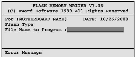
- Type the filename of the new BIOS in the "File Name to Program" text box. Follow the onscreen directions to update the motherboard BIOS.
- When the installation is complete, remove the floppy diskette from the diskette drive and restart your computer. If your motherboard has a Flash BIOS jumper, reset the jumper to protect the newly installed BIOS from being overwritten.
Using BIOS
When you start the Setup Utility, the main menu appears. The main menu of the Setup Utility displays a list of the options that are available. A highlight indicates which option is currently selected. Use the cursor arrow keys to move the highlight to other options. When an option is highlighted, execute the option by pressing
Some options lead to pop-up dialog boxes that prompt you to verify that you wish to execute that option. Other options lead to dialog boxes that prompt you for information.
Some options (marked with a triangle ) lead to submenus that enable you to change the values for the option. Use the cursor arrow keys to scroll through the items in the submenu.
In this manual, default values are enclosed in parenthesis. Submenu items are denoted by a triangle .
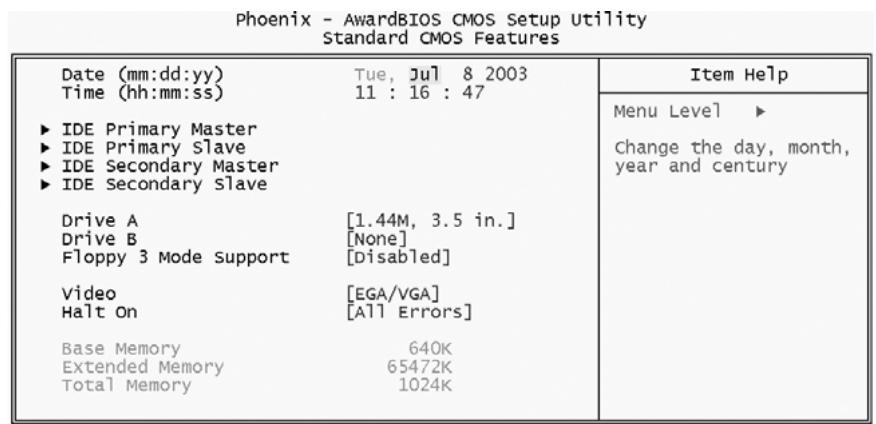
Standard CMOS Features
In the Standard CMOS menu you can set the system clock and calendar, record disk drive parameters and the video subsystem type, and select the type of errors that stop the BIOS POST.
```python
11--:Move Enter:Select +/-/PU/PD:Value F10:Save ESC:Exit F1:General Help
F5:Previous Values F6:Fail-Safe Defaults F7:Optimized Defaults
Date and Time
The Date and Time items show the current date and time on the computer. If you are running a Windows OS, these items are automatically updated whenever you make changes to the Windows Date and Time Properties utility.
IDE Devices (None)
Your computer has two IDE channels (Primary and Secondary) and each channel can be installed with one or two devices (Master and Slave). Use these items to configure each device on the IDE channel.
Press
Phoenix - AwardBIOS CMOS Setup Utility IDE Primary Master
| IDE HDD Auto-Detection | [Press Enter] | Item Help |
| IDE Primary Master | [Auto] | Menu Level ▶ ▶ |
| Access Mode | [Auto] | To auto-detect the HDD's size, head ... on this channel |
| Capacity | 0 MB | |
| Cylinder | 0 | |
| Head | 0 | |
| Precomp | 0 | |
| Landing Zone | 0 | |
| Sector | 0 |

:Move
Enter : Select
+/-/PU/PD:Value:
F10: Save
ESC: Exit F1:General Help
F5:Previous Values
F6:Fail-Safe Defaults
F7:Optimized Defaults
IDE HDD Auto-Detection
Press
Note: If you are setting up a new hard disk drive that supports LBA mode, more than one line will appear in the parameter box. Choose the line that lists LBA for an LBA drive.
IDE Primary/Secondary Master/Slave (Auto)
Leave this item at Auto to enable the system to automatically detect and configure IDE devices on the channel. If it fails to find a device, change the value to Manual and then manually configure the drive by entering the characteristics of the drive in the items described below.
Refer to your drive's documentation or look on the drive casing if you need to obtain this information. If no device is installed, change the value to None.
Note: Before attempting to configure a hard disk drive, ensure that you have the configuration information supplied by the manufacturer of your hard drive. Incorrect settings can result in your system not recognizing the installed hard disk.
Access Mode
This item defines ways that can be used to access IDE hard disks such as LBA (Large Block Addressing). Leave this value at Auto and the system will automatically decide the fastest way to access the hard disk drive.
Press
Drive A/Drive B (1.44M, 3.5 in./None)
These items define the characteristics of any diskette drive attached to the system. You can connect one or two diskette drives.
Floppy 3 Mode Support (Disabled)
Floppy 3 mode refers to a 3.5-inch diskette with a capacity of 1.2 MB. Floppy 3 mode is sometimes used in Japan.
Video (EGA/VGA)
This item defines the video mode of the system. This motherboard has a built-in VGA graphics system; you must leave this item at the default value.
Halt On (All Errors)
This item defines the operation of the system POST (Power On Self Test) routine. You can use this item to select which types of errors in the POST are sufficient to halt the system.
Base Memory, Extended Memory, and Total Memory
These items are automatically detected by the system at start up time. These are display-only fields. You cannot make changes to these fields.
Advanced BIOS Features
This option defines advanced information about your system.
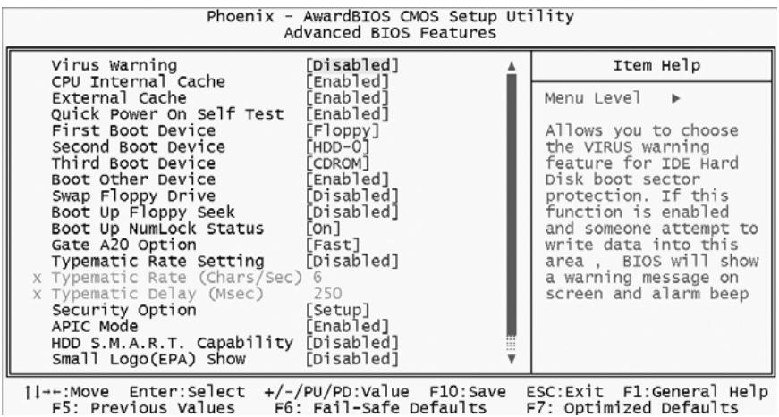
Virus Warning (Disabled)
When enabled, this item provides protection against viruses that try to write to the boot sector and partition table of your hard disk drive. You need to disable this item when installing an operating system. We recommend that you enable this item as soon as you have installed an operating system.
Note: For complete protection against viruses, install virus software in your operating system and update the virus definitions regularly.
CPU Internal Cache (Enabled)
All processors that can be installed in this motherboard use internal level 1 (L1) cache memory to improve performance. Leave this item at the default value for better performance.
External Cache (Enabled)
Most processors that can be installed in this system use external level 2 (L2) cache memory to improve performance. Leave this item at the default value for better performance.
Quick Power On Self Test (Enabled)
Enable this item to shorten the power on testing (POST) and have your system start up faster. You might like to enable this item after you are confident that your system hardware is operating smoothly.
First/Second/Third Boot Device (Floppy/HDD-0/CDROM)
Use these three items to select the priority and order of the devices that your system searches for an operating system at start-up time.
Boot Other Device (Enabled)
When enabled, the system searches all other possible locations for an operating system if it fails to find one in the devices specified under the First,
Second, and Third boot devices.
Swap Floppy Drive (Disabled)
If you have two floppy diskette drives in your system, this item allows you to swap the assigned drive letters so that drive A becomes drive B, and drive B becomes drive A.
Boot Up Floppy Seek (Disabled)
If this item is enabled, it checks the size of the floppy disk drives at start-up time. You don't need to enable this item unless you have a legacy diskette drive with 360K capacity.
Boot Up NumLock Status (On)
This item defines if the keyboard Num Lock key is active when your system is started.
Gate A20 Option (Fast)
This item defines how the system handles legacy software that was written for an earlier generation of processors. Leave this item at the default value.
Typematic Rate Setting (Disabled)
If this item is enabled, you can use the following two items to set the typematic rate and the typematic delay settings for your keyboard.
- Typematic Rate (Chars/Sec): Use this item to define how many characters per second are generated by a held-down key.
- Typematic Delay (Msec): Use this item to define how many milliseconds must elapse before a held-down key begins generating repeat characters.
Security Option (Setup)
If you have installed password protection, this item defines if the password is required at system start up, or if it is only required when a user tries to enter the Setup Utility.
APIC Mode (Enabled)
This item allows you to enable APIC (Advanced Programmable Interrupt Controller) functionality. APIC is an Intel chip that provides symmetric multiprocessing (SMP) for its Pentium systems.
HDD S.M.A.R.T Capability (Disabled)
The S.M.A.R.T. (Self-Monitoring, Analysis, and Reporting Technology) system is a diagnostics technology that monitors and predicts device performance. S.M.A.R.T. software resides on both the disk drive and the host computer.
The disk drive software monitors the internal performance of the motors, media, heads, and electronics of the drive. The host software monitors the overall reliability status of the drive. If a device failure is predicted, the host software, through the Client WORKS S.M.A.R.T applet, warns the user of the impending condition and advises appropriate action to protect the data.
Small Logo (EPA) Show (Disabled)
Determines whether or not the EPA logo appears during boot up.
ATA 66/100 Cable MSG (Enabled)
This item enables or disables the display of the ATA 66/100 Cable MSG.
Advanced Chipset Features
The Advanced Chipset Features option is used to change the values of the chipset registers. These registers control most of the system options in the computer. You should leave the items on this page at their default values, if you change the values incorrectly, you may introduce fatal errors or recurring instability into your system.
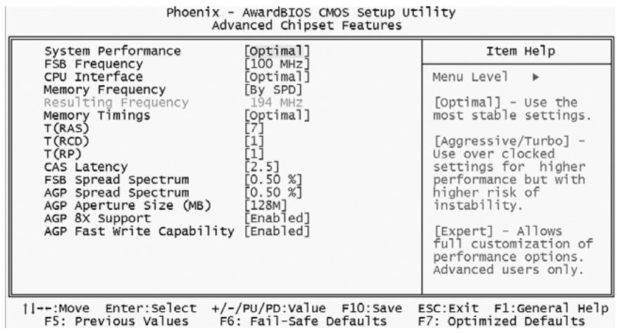
System Performance (Optimal)
[Optimal] - Use for stable settings.
[Aggressive/Turbo] - Use for overclocking.
[Expert] - Allows full customization of performance options. This is for advanced users only.
FSB Frequency (100 MHz)
This item is for selecting the FSB frequency.
CPU Interface (Optimal)
[Optimal] - Use for stable settings.
[Aggressive/Turbo] - Use for overclocking.
Memory Frequency (By SPD)
This item is for selecting the DDR SDRAM frequency.
Resulting Frequency (194 MHz)
This item shows the DDR SDRAM frequency you've selected in the previous item.
Memory Timings (Optimal)
This item allows you to set the Memory Timings. The following four items become available when this item is set to Expert.
T(RAS) (7)
This item defines the timing delay for DRAM precharge.
T(RCD) (1)
This item defines the timing of the transition from RAS (row address strobe) to CAS (column address strobe) as both rows and columns are separately addressed shortly after DRAM is refreshed.
T(RP) (1)
This item defines the numbers of cycles for RAS to be allowed to precharge.
CAS Latency (2.5)
This item defines the timing delay in clock cycles before SDRAM starts a read command after receiving it.
FSB Spread Spectrum (0.50%)
This item allows you to set the FSB spread spectrum modulation.
AGP Spread Spectrum (0.50%)
This item allows you to set the AGP spread spectrum modulation.
AGP Aperture Size (MB) (128M)
The DRAM timing is controlled by the DRAM Timing Registers. The Timings programmed into this register are dependent on the system design. Slower rates may be required in certain system designs to support loose layouts or slower memory.
AGP 8X Support (Enabled)
This item allows you to enable or disable AGP 8X Support.
AGP Fast Write Capability (Enabled)
This item enables an end sure to manually select the AGP output buffer driver strength.
Integrated Peripherals
These options display items that define the operation of peripheral components on the system's input/output ports.
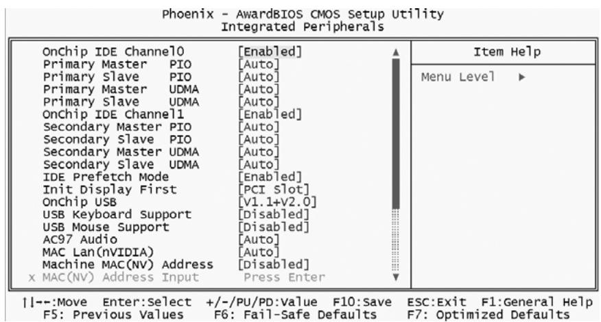
OnChip IDE Channel 0/Channel 1 (Enabled)
The chipset contains a PCI IDE interface with support to two IDE channels. Select Enabled to activate the primary/secondary IDE interface. Select Disabled to deactivate the primary/secondary interface.
Primary/Secondary Master/Slave PIO (Auto)
The four IDE PIO (Programmed Input/Output) fields let you set a PIO mode (0-4) for each of the four IDE devices that the onboard IDE interface supports. Modes 0 through 4 provide successively increased performance. In Auto mode, the system automatically determines the best mode for each device.
Primary/Secondary Master/Slave UDMA (Auto)
Ultra DMA/100 implementation is possible only if your IDE hard drive supports it and the operating environment includes a DMA driver (Windows 95 OSR2 or a third-party IDE bus master driver). If both of your hard drive and your system software support Ultra DMA/100, select Auto to enable BIOS support.
IDE Prefetch Mode (Enabled)
The onboard IDE drive interface support IDE prefetching for faster drive access. If you install a primary and/or secondary add-on IDE interface, set this field to Disabled if the interface does not support prefetching.
Init Display First (PCI Slot)
This item is used to determine initial device when system power on.
OnChip USB (V1.1+v2.0)
This should be enabled if your system has a USB installed on the system board and you want to use it.
USB Keyboard Support (Disabled)
Select Enabled if your system contains a Universal Serial Bus (USB) controller and you have a USB keyboard.
AC97 Audio (Auto)
This item allows you to control the onboard AC97 Audio.
MAC Lan (nVIDIA) (Auto)
This option allows you to enable/disable the Onboard LAN Controller.
Machine MAC (NV) Address (Disabled)
This option allows you to enable/disable the Onboard LAN Controller Address setting.
IDE DMA transfer access (Enabled)
This item allows you to enable the transfer access of the IDE DMA then burst onto the PCI bus and nonburstable transactions do not.
IDE HDD Block Mode (Enabled)
Block mode is also called block transfer, multiple commands, or multiple sector read/write. If your IDE hard drive supports block mode(most new drivers do), select Enabled for automatic detection of the optimal number of block read/write per sector the drive can support.
Onboard FDC Controller (Enabled)
This item specifies the onboard floppy disk drive controller. This setting allows you to connect your floppy disk drives to the onboard floppy connector.
Onboard Serial Port 1 (378/IRQ7)
This option is used to assign the I/O address and interrupt request (IRQ) for the onboard serial port 1 (COM1).
Onboard Parallel Port (378/IRQ7)
This item allows you to determine an I/O address and interrupt request (IRQ) for the onboard parallel port.
Parallel Port Mode (ECP)
Select an operating mode for the onboard parallel port. Select ULTRA-400 unless you are certain your system supports other modes.
ECP Mode Use DMA
When the parallel port mode is set to ECP, this item becomes selectable.
Power Management Setup
The Power Management Setup Menu option is used to change the values of the chipset registers for system power management.
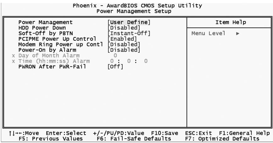
Power Management
This category allows you to select the type (or degree) of power saving mode settings.
Min Saving Minimum power management. Suspend Mode=1 hr.
Max Saving Maximum power management.Suspend Mode=1 min.
User Define Allows you to set each mode individually. Suspend Mode= Disabled or 1 min ~1 hr.
HDD Power Down (Disabled)
The IDE hard drive will spin down if it is not accessed within a specified length of time.
Soft-Off by PBTN (Instant-Off)
Pressing the power button for more than 4 seconds forces the system to enter the Soft-Off state when the system has "hang".
PCIPME Power Up Control (Enabled)
Use this item to enable PCI activity to wakeup the system from a power saving mode.
Modem Ring Power up Contl (Disabled)
Use this item to enable the modem ring to wakeup the system from a power saving mode.
Power-On by Alarm (Disabled)
When set to Enabled, the following three fields become available and you can set the hour, minute and second to turn on your system.
PWRON After PWR-Fail (Off)
This item allows you to select power on function when power fail.
PNP/PCI Configurations
This option configures how PnP (Plug and Play) and PCI expansion cards operate in your system. Both the ISA and PCI buses on the Motherboard use system IRQs (Interrupt ReQuests) and DMAs (Direct Memory Access). You must set up the IRQ and DMA assignments correctly through the PnP/PCI Configurations Setup utility for the motherboard to work properly. Selecting PnP/PCI Configurations on the main program screen displays this menu:
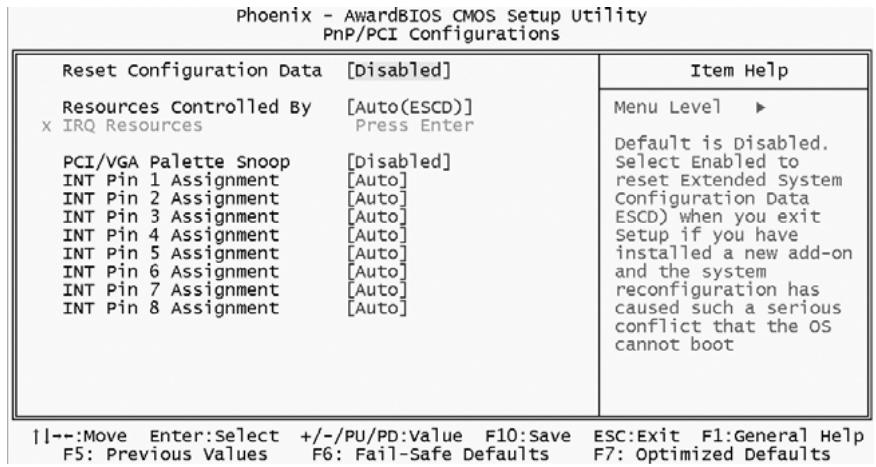
Reset Configuration Data (Disabled)
If enabled, this feature will reset the Extended System Configuration Data (ESCD) upon exiting Setup. This may correct hardware conflicts that prevent the Operating System from booting.
Resources Controlled By (Auto (ESCD))
You should leave this item at the default Auto (ESCD). Under this setting, the system dynamically allocates resources to Plug and Play devices, as they are required.
If you cannot get a legacy ISA (Industry Standard Architecture) expansion card to work properly, you might be able to solve the problem by changing this item to Manual, and then opening up the IRQ Resources and Memory Resources submenus.
In the IRQ Resources submenu, if you assign an IRQ to Legacy ISA, then that Interrupt Request Line is reserved for a legacy ISA expansion card. Press
In the Memory Resources submenu, use the first item Reserved Memory Base to set the start address of the memory you want to reserve for the ISA expansion card. Use the second item Reserved Memory Length to set the amount of reserved memory. Press
IRQ Resources (Press Enter)
When the previous item is set to manual, this item allows you respectively assign an interruptive type for IRQ-3, 4, 5, 7, 9, 10, 11, 12, 14, and 15.
PCI/VGA Palette Snoop (Disabled)
This item is designed to overcome problems that can be caused by some non-standard VGA cards. This board includes a built-in VGA system that does not require palette snooping so you must leave this item disabled.
INT Pin1~8 Assignment (Auto)
Names the interrupt request (IRQ) line assigned to a device connected to the PCI interface on your system.
PC Health Status
On motherboards that support hardware monitoring, this item lets you monitor the parameters for critical voltages, critical temperatures, and fan speeds.
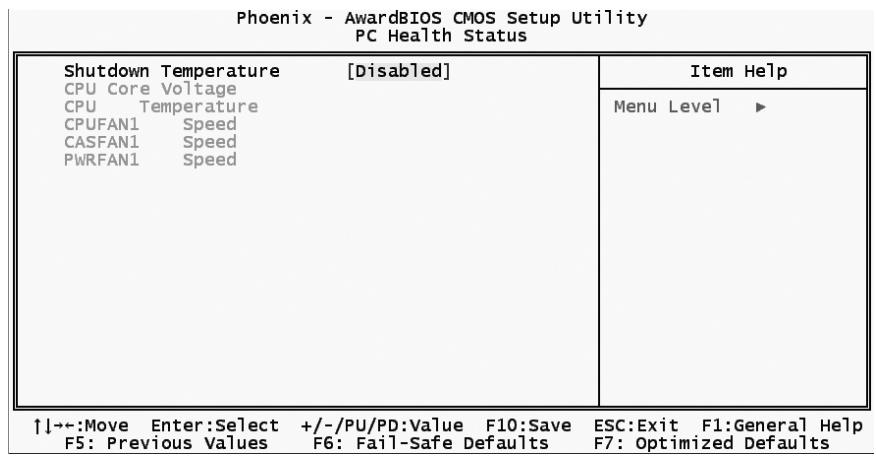
Shutdown Temperature (Disabled)
Enables you to set the maximum temperature the system can reach before powering down.
System Component Characteristics
These items allow end users and technicians to monitor data provided by the BIOS on this motherboard. You cannot make changes to these fields.
CPU Core voltage
CPU Temperature
CPUFAN1 Speed
CASFAN1 Speed
PwRFAN1 Speed
Load Fail-Safe Defaults
This option opens a dialog box that lets you install fail-safe defaults for all appropriate items in the Setup Utility:
Press
Load Optimized Defaults
This option opens a dialog box that lets you install optimized defaults for all appropriate items in the Setup Utility. Press
Set Supervisor/User Password
When this function is selected, the following message appears at the center of the screen to assist you in creating a password.
ENTER PASSWORD
Type the password, up to eight characters, and press
To disable password, just press
password DISABLED
If you have selected "System" in "Security Option" of "BIOS Features Setup" menu, you will be prompted for the password every time the system reboots or any time you try to enter BIOS Setup.
If you have selected "Setup" at "Security Option" from "BIOS Features Setup" menu, you will be prompted for the password only when you enter BIOS Setup.
Supervisor Password has higher priority than User Password. You can use Supervisor Password when booting the system or entering BIOS Setup to modify all settings. Also you can use User Password when booting the system or entering BIOS Setup but can not modify any setting if Supervisor Password is enabled.
Save & Exit Setup
Highlight this item and press
Exit Without Saving
Highlight this item and press
Note: If you have made settings that you do not want to save, use the "Exit Without Saving" item and press <Y> to discard any changes you have made.
This concludes Chapter 3. Refer to the next chapter for information on the software supplied with the motherboard.
Using the Motherboard Software
About the Software CD-ROM
The support software CD-ROM that is included in the motherboard package contains all the drivers and utility programs needed to properly run the bundled products. Below you can find a brief description of each software program, and the location for your motherboard version. More information on some programs is available in a README file, located in the same directory as the software.
Note: Never try to install software from a folder that is not specified for use with your motherboard.
Before installing any software, always inspect the folder for files named README.TXT, INSTALL.TXT, or something similar. These files may contain important information that is not included in this manual.
Auto-installing under Windows 98/ME/2000/XP
The Auto-install CD-ROM makes it easy for you to install the drivers and software for your motherboard.
Note: If the Auto-install CD-ROM does not work on your system, you can still install drivers through the file manager for your OS (for example, Windows Explorer). Refer to Utility Folder Installation Notes later in this chapter.
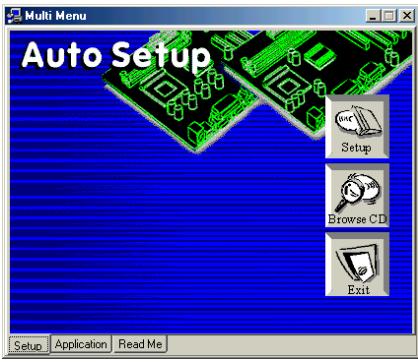
The support software CD-ROM disc loads automatically under Windows 98/ME/2000/XP. When you insert the CD-ROM disc in the CD-ROM drive, the autorun feature will automatically bring up the install screen. The screen has three buttons on it, Setup, Browse CD and Exit.
Note: If the opening screen doesn't appear, double-click the file "setup.exe" in the root directory.
Setup Tab
| Setup | Click the Setup button to run the software installation program. Select from the menu which software you want to install. |
| Browse CD | The Browse CD button is the standard Windows command that allows you to open Windows Explorer and show the contents of the support CD.Before installing the software from Windows Explorer, look for a file named README.TXT, INSTALL.TXT or something similar. This file may contain important information to help you install the software correctly.Some software is installed in separate folders for different oper-ating systems, such as DOS, WIN NT, or WIN98/95. Always go to the correct folder for the kind of OS you are using.To install the software, execute a file named SETUP.EXE or INSTALL.EXE by double-clicking the file and then following the instructions on the screen. |
| Exit | The Exit button closes the Auto Setup window. |
Application Tab
Lists the software utilities that are available on the CD.
Read Me Tab
Displays the path for all software and drivers available on the CD.
Running Setup
Follow these instructions to install device drivers and software for the motherboard:
- Click Setup. The installation program begins:
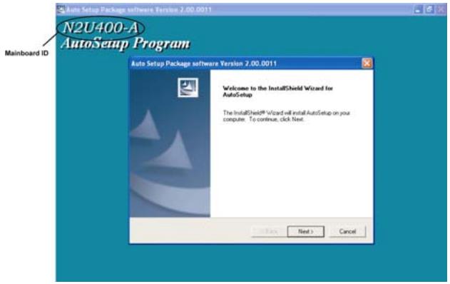
Note: The following screens are examples only. The screens and driver lists will be different according to the motherboard you are installing.
The motherboard identification is located in the upper left-hand corner.
- Click Next. The following screen appears:
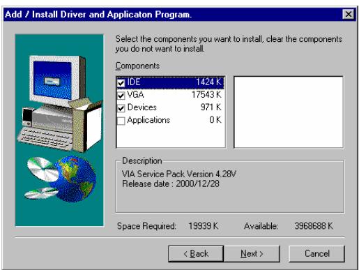
- Check the box next to the items you want to install. The default options are recommended.
- Click Next run the Installation Wizard. An item installation screen appears:
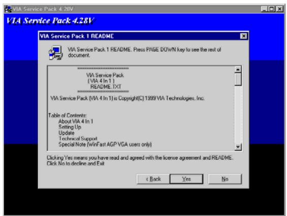
- Follow the instructions on the screen to install the items.
Drivers and software are automatically installed in sequence. Follow the on-screen instructions, confirm commands and allow the computer to restart a few times to complete the installation.
Manual Installation
Insert the CD in the CD-ROM drive and locate the PATH.DOC file in the root directory. This file contains the information needed to locate the drivers for your motherboard.
Look for the chipset and motherboard model; then browse to the directory and path to begin installing the drivers. Most drivers have a setup program (SETUP.EXE) that automatically detects your operating system before installation. Other drivers have the setup program located in the operating system subfolder.
If the driver you want to install does not have a setup program, browse to the operating system subfolder and locate theREADME text file (README.TXT or README.DOC) for information on installing the driver or software for your operating system.
Utility Software Reference
All the utility software available from this page is Windows compliant. They are provided only for the convenience of the customer. The following software is furnished under license and may only be used or copied in accordance with the terms of the license.
Note: These software(s) are subject to change at anytime without prior notice. Please refer to the support CD for available software.
AWARD Flash Memory Utility
This utility lets you erase the system BIOS stored on a Flash Memory chip on the motherboard, and lets you copy an updated version of the BIOS to the chip. Proceed with caution when using this program. If you erase the current BIOS and fail to write a new BIOS, or write a new BIOS that is incorrect, your system will malfunction. Refer to Chapter 3, Using BIOS for more information.
WinFlash Utility
The Award WinFlash utility is a Windows version of the DOS Award BIOS flash writer utility. The utility enables you to flash the system BIOS stored on a Flash Memory chip on the motherboard while in a Windows environment. This utility is currently available for WINXP\ME\2000\98SE. To install the WinFlash utility, run WINFLASH.EXE from the following directory:
\UTILITY\WINFLASH 1.51
PC-CILLIN
The PC-CILLIN software program provides anti-virus protection for your system. This program is available for Windows 2000/ME/98SE/XP and Windows NT. Be sure to check theREADME.txt and install the appropriate anti-virus software for your operating system.
We strongly recommend users to install this free anti-virus software to help protect your system against viruses.
This concludes Chapter 4.