
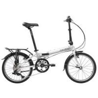
DOMAIN - Folding bike DAHON - Free user manual and instructions
Find the device manual for free DOMAIN DAHON in PDF.
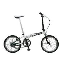
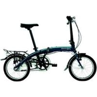
| Product Type | Folding bike |
| Brand | DAHON |
| Model | DOMAIN |
| Category | Folding bike |
| Suspension type | Telescopic pneumatic spring fork (RockShox) |
| Travel | Adjustable via U-Turn system (by 7.5 mm increments) |
| Positive air pressure | Variable depending on rider weight (4.8 to 12.4 bar) |
| Negative air pressure | Equal to positive pressure (adjustable) |
| Damping | Motion Control with compression and rebound adjustments |
| Compatible brakes | V-brakes, cantilevers or disc brakes |
| Maximum tire size | 2.7 inches |
| Steerer tube material | Carbon (Reba World Cup model) or steel |
| Upper tube maintenance | Clean after each ride |
| Lubrication of seals | Every 10 hours of pedaling |
| Lower tube oil change | Every 50 hours |
| Damping oil change | Every 100 hours |
| Safety | Use only RockShox parts, check brakes before each use |
| Warranty | 2 years against material and manufacturing defects |
| Wear parts | Seals, bushings, upper tubes, etc. |
| Repairability | Maintenance recommended by a professional mechanic |
Frequently Asked Questions - DOMAIN DAHON
User questions about DOMAIN DAHON
0 question about this device. Answer the ones you know or ask your own.
Ask a new question about this device
Download the instructions for your Folding bike in PDF format for free! Find your manual DOMAIN - DAHON and take your electronic device back in hand. On this page are published all the documents necessary for the use of your device. DOMAIN by DAHON.
USER MANUAL DOMAIN DAHON
You have the best in suspension components on your bicycle! This manual contains important information about the safe operation and maintenance of your fork. To ensure that your RockShox fork performs properly, we recommend that you have your fork installed by a qualified bicycle mechanic. We also urge you to follow our recommendations to help make your riding experience more enjoyable and trouble-free.
IMPORTANT
CONSUMER SAFETY INFORMATION
- The fork on your bicycle is designed for use by a single rider, on mountain trails, and similar off-road conditions.
- Before riding the bicycle, be sure the brakes are properly installed and adjusted. Use your brakes carefully and learn your brakes' characteristics by practicing your braking technique in non-emergency circumstances. Hard braking or improper use of the front brake can cause you to fall. If the brakes are out of adjustment, improperly installed or are not used properly, the rider could suffer serious and/or fatal injuries.
- Your fork may fail in certain circumstances, including, but not limited to, any condition that causes a loss of oil; collision or other activity bending or breaking the fork's components or parts; and extended periods of non-use Fork failure may not be visible. Do not ride the bicycle if you notice bent or broken fork parts, loss of oil, sounds of excessive topping out, or other indications of a possible fork failure, such as loss of shock absorbing properties. Instead, take your bike to a qualified dealer for inspection and repair. In the event of a fork failure, damage to the bicycle or personal injury may result.
- Always use genuine RockShox parts. Use of aftermarket replacement parts voids the warranty and could cause structural failure to the shock. Structural failure could result in loss of control of the bicycle with possible serious and/or fatal injuries.
- Use extreme caution not to tilt the bicycle to either side when mounting the bicycle to a carrier by the fork drop-outs (front wheel removed). The fork legs may suffer structural damage if the bicycle is tilted while the drop-outs are in the carrier. Make sure the fork is securely fastened down with a quick release. Make sure the rear wheel is fastened down when using ANY bike carrier that secures the forks drop-outs. Not securing the rear can allow the bikes mass to side-load the drop-outs, causing them to break or crack. If the bicycle tilts or falls out of its carrier, do not ride the bicycle until the fork is properly examined for possible damage. Return the fork to your dealer for inspection or call RockShox if there is any question of possible damage (See the International Distributor List). A fork leg or drop-out failure could result in loss of control of the bicycle with possible serious and/or fatal injuries.
- Forks designed for use with 'v'-style brakes: only mount cantilever-type brakes to the existing brake posts. Forks with hangerless style braces are only designed for V-style or hydraulic cantilever brakes. Do not use any cantilever brake other than those intended by the brake manufacturer to work with a hangerless brace. Do not route the front brake cable and/or cable housing through the stem or any other mounts or cable stops. Do not use a front brake cable leverage device mounted to the brace. Forks designed for use with disc-style brakes: follow the brake manufacturer's installation instruction for proper installation and mounting of the brake caliper.
- Observe all owner's manual instructions for care and service of this product.
ROCKSHOX FORKS ARE DESIGNED FOR COMPETITIVE OFF-ROAD RIDING AND DO NOT COME WITH THE PROPER REFLECTORS FOR ON-ROAD USE. YOUR DEALER SHOULD INSTALL PROPER REFLECTORS TO MEET THE CONSUMER PRODUCT SAFETY COMMISSIONIS (CPSC) REQUIREMENTS FOR BICYCLE STANDARDS IF THE FORK IS GOING TO BE USED ON PUBLIC ROADS AT ANY TIME.
FORK INSTALLATION
It is extremely important that your RockShox fork is installed correctly by a qualified bicycle mechanic. Improperly installed forks are extremely dangerous and can result in severe and/or fatal injuries.
- Remove the existing fork from the bicycle and the crown race from the fork. Measure the length of the fork steerer tube against the length of the RockShox steerer tube. The RockShox steerer tube may need cutting to the proper length. Make sure there is sufficient length to clamp the stem (refer to the stem manufacturer's instructions).
WARNING
DO NOT ADD THREADS TO ROCKSHOCK THREADLESS STEERERS THE STEERER TUBE CROWN ASSEMBLY IS A ONE-TIME PRESS FIT. REPLACEMENT OF THE ASSEMBLY MUST BE DONE TO CHANGE THE LENGTH, DIAMETER OR HEADSET TYPE (THREADED OR THREADLESS).
DO NOT REMOVE OR REPLACE THE STEERER TUBE. THIS COULD RESULT IN THE LOSS OF CONTROL OF THE BICYCLE WITH POSSIBLE SERIOUS AND/OR FATAL INJURIES.
- Install the headset crown race (29.9mm for 1 1/8" steers) firmly against the top of the fork crown. Install the fork assembly on the bike. Adjust the headset until you feel no play or drag.
- Install the brakes according to the manufacturer's instructions and adjust brake pads properly. Use the fork only with disc style brakes mounted through the provided mounting holes. Do not use any cantilever brake other than those intended by the brake manufacturer to work with a hangerless brace.
- Forks designed for standard quick releases: adjust the front wheel quick release to clear the dropout's counter bore. The quick release nut must be tightened after the wheel is properly seated into the dropout's counter bore. Make sure four or more threads are engaged in the quick release nut when it is closed. Orient the quick release lever in front of and parallel to the lower tube in the locked position. Forks designed for a thru-axle (not available for all forks): follow the installation instructions that follow for the Maxle Quick Release system.
- Keep in mind tire clearance as you choose tires. Maximum size is:
FORK MAX TIRE SIZE (INSTALLED)
| Pike | 2.5" |
| Reba | 2.4" |
| Revelation | 2.5" |
| Argyle | 2.5" |
| Domain | 2.7" |
Be sure to check this diameter whenever you change tires. To do this, remove air pressure and compress the fork completely to make sure at least 5mm of clearance exists between the top of the tire and the bottom of the crown. Exceeding maximum tire size will cause the tire to jam against the crown when the fork is fully compressed.
CARBON CROWN-STEERER INSTALLATION (Reba World Cup only)
The World Cup is designed for cross-country riding and racing. The one piece carbon crown-steerer accounts for the unique loads and stresses of mountain bike riding, while providing vibration damping and ride control unmatched by traditional material technologies.
It is extremely important that your fork is installed correctly by a qualified bicycle mechanic. Improperly installed forks are extremely dangerous and can result in severe and/or fatal injuries.
For installation, follow the instructions below as well as the instructions in your owner's manual.
- The steerer tube must be cut flush with the top of the stem. Apply masking tape to the top of the steerer tube to help prevent carbon fraying during cutting. Use a minimum 28-tooth blade to cut the carbon steerer. For safe handling, smooth the cut surface area with 400 grit sand paper.
- Install a 2mm spacer above the stem to allow for proper headset adjustment Do not exceed the 30mm maximum stack height when installing spacers (Fig. 1).
- Do not use star nuts. Use only expansion style plugs such as the one supplied with the fork. Do not exceed 100 in-lb of torque to the expansion plug bolt. Torque values may vary depending on headset design and condition.
- To prevent damage to the carbon crown-steerer, a qualified technician should take care when installing or removing the crown race.
- Remove any burrs from the stem stem clamp edges before installation on the carbon crown-steerer. Do not use a hammer to install your stem.
- Follow the stem manufacturer's torque specifications when installing a stem. Exceeding the torque specifications may damage the carbon crown-steerer and reduce the strength of the fork. Cotter style stems are not recommended as the small surface area may cause damage, especially when overtorqued.
- Do not let brake or deraillaur cables rest on, or be attached to the crown. Abrasion over time may cause damage to the crown. If contact is unavoidable, use tape or similar protection to cover the surface. Important: Crown abrasion is not covered under warranty.
- Take your bicycle to a qualified dealer for inspection and repair if there is any question of component integrity due to a crash or other direct impact.
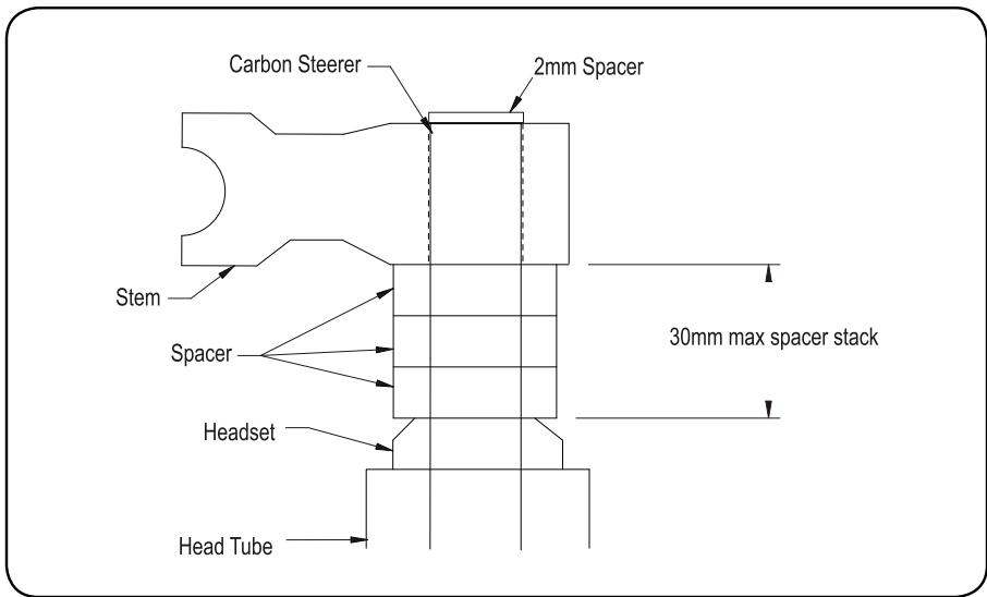
Fig. 1
REMOTE INSTALLATION
The PopLoc or PushLoc Remote Lockout lever allows the rider to control the movement of their suspension fork without removing their hands from the handlebars. Specific left and right levers are available.
If needed, remove the grip, brake lever, and shifter from the handlebar. If you are unfamiliar with the removal of these items, please consult the manufacturer's instructions.
- Slide the Poploc onto the handlebar, or install the PushLoc on the handlebars.
- Re-install the shifter, brake lever, and grip on the handlebars. If you are unfamiliar with the installation of these items, please consult the manufacturer's instructions. Always adhere to the recommended torque specifications for these items.
- Position the PopLoc or PushLoc as desired on the handlebar and tighten the clamp bolt to 20in-lb (2.25 Nm).
- Forks with PopLoc Adjust: Turn the blue compression adjustment dial counterclockwise until it stops.
- Verify that the PushLoc or PopLoc is in the "open" position. To do this, press the lever on the PushLoc until it returns towards the rider. Press the release button on the PopLoc.
- Install the cable in the PopLoc or PushLoc.
- Install the cable into the housing.
- Feed the cable and housing into the cable stop on the fork crown.
- Gently pull on the cable and align it with the groove in the rotating cam of the Motion Control damper.
- Tighten the cable fixing bolt on the rotating cam to 8in-lb (.9 Nm).
IMPORTANT
CONSUMER SAFETY INFORMATION
The Maxle Quick Release system allows the use of a standard 20mm X 110mm thru-axle hub for enhanced stiffness. The axle threads into the left fork leg, tightening the hub against the left drop out. The axle is fixed in place in the lower leg by the Maxle Quick Release lever.
Riding with an improperly installed wheel can allow the wheel to move or disengage from the bicycle, causing damage to the bicycle, and serious injury or death to the rider. It is essential that that you:
- Ensure that your axle, dropouts, and quick release mechanisms are clean and free of dirt or debris.
- Ask your dealer to help you understand how to properly secure your front wheel using the Maxle Quick Release System.
- Apply the correct techniques when installing your front wheel.
- Never ride your bicycle unless you are sure the front wheel is installed properly and secure.
MAXLE 360^ QUICK RELEASE SYSTEM
INSTALLATION
- Position your wheel in the dropouts of the lower leg. The hub should seat firmly in the dropouts. Be sure to position the rotor in the caliper. Verify that neither the rotor, hub, nor rotor bolts interfere with the lower legs. If unfamiliar with adjusting your disc brake, see your brake manufacturer's instruction.
Tighten
- Place Maxle lever in the open position (Fig. A). Ensure the lever engages with the corresponding slot in the axle.
- Slide the axle through the right side of the hub until it engages the threads of the left drop out.
- To tighten the axle into the dropout, turn the axle lever clockwise until hand tight.
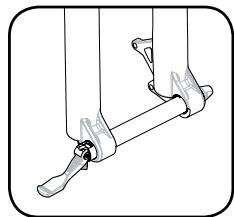
Fig. A

WARNING
DIRT AND DEBRIS CAN ACCUMULATE BETWEEN THE DROPOUT OPENINGS. ALWAYS CHECK AND CLEAN THIS AREA WHEN REINSTALLING THE WHEEL. ACCUMULATED DIRT AND DEBRIS CAN COMPROMISE THE SECURITY OF THE AXLE, LEADING TO SERIOUS AND/OR FATAL INJURY.
Notes: Never use any other tool to tighten the axle into the lower leg. Over-tightening of the axle can damage the axle and/or the lower leg.
Secure
- To lock the axle into the lower leg close the Maxle quick release lever.
- The quick release mechanism is an "over-center cam", similar to the quick release found on many bicycle wheels. When closing the lever, tension should be felt when the quick release lever is in the horizontal position (90 degrees to the lower leg), and the quick release lever should leave an imprint in the palm of your hand. If resistance is not felt at the 90 degree position and if the lever does not leave a clear imprint in the palm of your hand, tension is insufficient. To increase tension, open the quick release lever turn the quick release lock nut in small increments until proper tension is felt.
A small (1-2mm) gap may be noticed between the inside flange of the maxle and the outside of the dropout. This gap is normal, and allows the right leg to "Float" in position prior to closing of the quick release.

WARNING
AFTER CLOSING THE MAXLE QUICK RELEASE LEVER, DO NOT REPOSITION OR SPIN THE LEVER. REPOSITIONING OR SPINNING THE MAXLE LEVER CAN CAUSE THE AXLE TO COME LOOSE, COMPROMISING THE SECURITY OF THE AXLE.
PERFORMANCE TUNING
RockShox forks can be tuned for your particular weight, riding style and terrain.
SETTING SAG
RockShox forks are designed to sag when you are sitting on your bike. Sag is the compression of the fork caused by the rider's weight. Proper sag allows the front wheel to follow the contour of the terrain as you ride.
To measure sag, set the fork to maximum travel. Install a zip tie on the upper tube of the fork flush against the wiper seal. Sit on the bike with normal riding apparel. Step off the bike, and measure the distance between the wiper seal and the zip tie. This is your sag. The sag should be between 15 and 25 percent of maximum travel. If you're unable to achieve optimum sag you may need to change the fork's air pressure or spring.
Use the tuning information below to assist in proper set up of your fork.
AIR SPRING TUNING
DUAL AIR (PIKE, REBA, REVELATION)
With independently adjustable positive (top) and negative (bottom) air chambers, the air spring system of your fork can be easily tuned for your weight and riding style. Use the following instructions as a starting point. If further fine tuning is desired, follow the hints at the end of this section.
Step 1 - Selecting Positive Air Pressure
Positive air pressure determines the amount of force required to compress your fork. More positive air pressure will result in less suspension sag and higher bottom out forces. Less positive air pressure will result in more suspension sag and lower bottom out forces.
Using the chart below as a guideline, inflate the positive air chamber to the desired pressure.
Note: Air U-Turn pressure should be set at maximum travel.
| RIDER WEIGHT | (Reba/Pike/Revelation) DUAL AIR | (Reba/Pike/Revelation) AIR U-TURN |
| < 140 (63kg) | 70 - 90 psi | 90 - 115 psi |
| 140 - 160 (63 - 72kg) | 90 - 105 psi | 115 - 130 psi |
| 160 - 180 (72 - 81kg) | 105 - 120 psi | 130 - 145 psi |
| 180 - 200 (81 - 90kg) | 120 - 135 psi | 145 - 160 psi |
| >220 (99kg) | 150 psi | 175 psi |
Step 2 - Selecting Negative Air Pressure
Negative air pressure effects the amount of force required to initiate suspension travel. Negative air pressure works with bump input AGAINST the force of the positive air chamber. More negative air pressure results in a suspension set-up that is more active, especially to small bump input. Less negative air pressure results in a suspension set-up that does not move or "bob" under rider input or small bumps. Start with the negative air pressure equal to the positive air pressure and then increase or decrease it as desired.
SOLO AIR (ARGYLE)
The positive and negative air chambers with these forks fill simultaneously from a single valve. The air spring is designed so the pressure in the two separate chambers equalizes as air is added, simplifying setup and providing a balanced ride.
Note: When adding air to the fork, a user may see a sudden drop in the air pressure reading on their shock pump. This is normal and indicates that the negative air chamber has opened and the pressure between the chambers has equalized. The user should continue to add air to the fork until the predetermined pressure is met.
Setting Solo Air:
Remove the air cap on the air valve located on the rider's left side of the fork crown by turning counterclockwise. Using the air chart below as a guideline, inflate the air chambers to the desired pressure.
| RIDER WEIGHT | (Argyle) SOLO AIR |
| < 140 (63kg) | 120 - 135 psi |
| 140 - 160 (63 - 72kg) | 135 - 150 psi |
| 160 - 180 (72 - 81kg) | 150 - 165 psi |
| 180 - 200 (81 - 90kg) | 165 - 180 psi |
| > 220 (99kg) | 180+ psi |
| Do not exceed 220 psi. | |
COIL SPRING TUNING
Changing the Spring Rate
Spring rate is the amount of force needed to compress a spring one inch. Changing your fork's coil spring for a spring of a higher or lower rate will alter the overall feel of your fork. Higher spring rates make the fork feel more "stiff", while lower spring rates make the fork more "supple". Contact your local RockShox dealer to order replacement springs.
Note: When decreasing travel (see "U-Turn travel adjust"), you increase the spring rate.
TRAVEL ADJUSTMENTS
Important: Stop turning the U-turn adjuster knob after you've reached maximum travel. Turning the knob past this point may cause damage to the U-turn feature.
Note: Ensure the fork is compressed once after sitting for more than a day and in "Open" position before travel adjustment.
Coil U-turn Travel Adjust (Domain, Pike, Revelation)
U-Turn forks offer 45mm of travel adjustment. To determine the travel on your fork, use the travel gradients on the upper tube (except Domain).
Turning the U-turn adjuster knob counterclockwise increases travel. Each turn increases or decreases the travel by 7.5mm.
Air U-Turn Travel Adjust (Pike, Revelation, Reba)
To change the travel of your fork, turn the Air U-Turn knob (top left knob on fork). Clockwise rotation reduces the travel of the fork. Counterclockwise rotation increases the travel of the fork. The new travel setting can be seen by looking at the travel marking that remains exposed on the left upper tube when not sitting on the bike. The reduced travel setting will have slightly lower bottom out force, therefore additional compression damping may be desired.
Changing Travel (Argyle, Reba)
To change the travel of your fork you must perform a full service on your fork. To obtain service information or instructions, visit our website at www.rockshox.com or contact your local RockShox dealer or distributor.
REBOUND DAMPING
External Rebound Adjustment
Rebound damping controls the speed at which a fork returns to its full extension following compression. Located at the bottom of the right fork leg is the rebound adjuster knob. Turning the adjuster in the direction indicated by the "rabbit" on the rebound speed decal decreases rebound damping, causing the fork to return to full extension faster. Turning the adjuster in the direction indicated by the "turtle" increases rebound damping, slowing the return of the fork to full extension.
Excessive rebound damping will cause the fork to "pack up" over successive bumps, reducing travel and causing the fork to bottom out. Set your fork to rebound as fast as possible without "topping out" or kicking back. This allows your fork to follow the contours of the trail, maximizing stability, traction and control.
Important: When storing a bicycle or fork upside-down or on its side, oil sealed in the upper tube can collect above the Motion Control Damper assembly. Upon returning the bicycle/fork to a normal riding position, initial performance of the Motion Control system may be less than optimal. To quickly return the fork to proper performance, return the fork to 'Open' position and cycle the fork through its travel 10-20 times. For information on returning your fork to 'Open' position, keep reading!
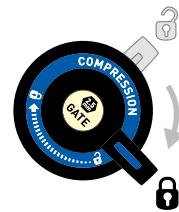
The Motion Control Damping system allows riders to quickly adjust the feel and performance of their suspension to match riding conditions without requiring pumps or tools. This system provides for wide-ranging control of compression and rebound damping as well as 'Lock' threshold sensitivity.
Proper setup of the Motion Control Damping system provides a range of options for efficient yet comfortable performance. The instructions below describe setup and operation for both crown and remote activated forks.
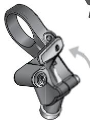
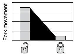
'Open' Compression (Fig. 1)
In the 'Open' position, the Motion Control Damping system allows for maximum compliance and fork movement. The 'Open' position provides ultimate control and comfort on even the roughest terrain.
To return your fork to the 'Open' position:
- For forks with the crown-mounted blue compression adjuster, rotate the adjuster fully counterclockwise.
- For PopLoc equipped forks, press the "unlock" release button on the remote (as indicated by the open padlock icon on the button).
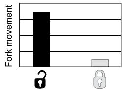
Motion Control - 'Open'
Compression at 'Open' level = maximum fork movement
Crown mounted adjuster
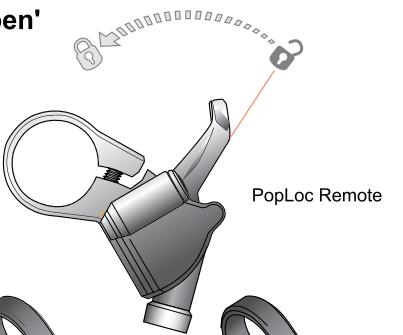

PopLoc Remote
PopLoc Adjust Remote
Fig. 1
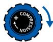
Motion Control - 'Lock'
Crown mounted adjuster
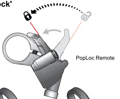
PopLoc Remote
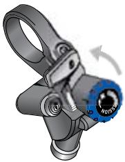
PopLoc Adjust Remote
Fig. 2
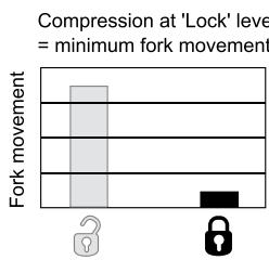
Lock' Compression (Fig. 2)
In the 'Lock' position, the Motion Control system allows for a small amount of controlled fork movement. This movement enables the front tire to track the terrain without deflecting off obstacles, allowing for better traction and steering control when compared to a complete lockout system. To activate the 'Lock', turn the crown-mounted blue compression adjuster full clockwise or press forward on the PopLoc Remote lever located on the handlebar.
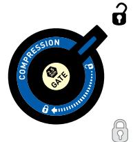
Floodgate Adjustment (Fig. 3) (Argyle 409, Pike, Revelation and Reba ONLY)
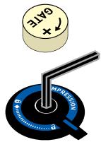
All forks with Motion Control Damping allow for fine-tuning of the 'Lock' setting. The rider can choose the point at which the 'Lock' setting can 'blow-off' and become active to force inputs such as bumps or rocks. This adjustment is made using the Floodgate. Depending upon fork model, the Floodgate is adjusted either internally (requires a 2.5mm hex wrench) or externally with the gold 'Gate' adjuster.
For crown mounted adjusters, hold the adjuster in the 'Lock' position while adjusting the internal Floodgate.
Note: The Floodgate is intended to adjust threshold of 'lock' blow-off in the 'lock' mode only. When performing Floodgate adjustments, ensure that the motion control system is adjusted to 'lock.'
Under 'Lock', the maximum Floodgate setting results in a fork with minimal movement while the minimum Floodgate setting results in increased fork movement.
Note: For maximum fork sensitivity and movement, return the fork to the 'open' position.
Floodgate settings should be used to adjust suspension compliance to medium sized bumps and resistance to rider induced suspension movement (referred to as "bob") in the 'Lock' mode. When properly tuned, the Motion Control System will resist "bob," but provide controlled suspension action in rough or aggressive terrain.
Floodgate Adjustment
('Lock' blowoff force when the fork is in 'Lock' mode)
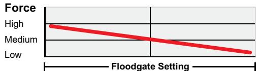
Minimum
Maximum
Floodgate in full clockwise position. High input force needed to overcome the 'Lock.'
Floodgate in full counterclockwise position. Low input force needed to overcome the 'Lock.'
External Floodgate
Internal Floodgate

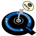
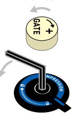
Fig. 3
Under 'Lock', heavier riders may find better performance with maximum Floodgate settings, while lighter riders may find minimum Floodgate settings work best. Experiment with higher or lower Floodgate settings while on the trail to optimize your fork for your riding style and performance preferences.
Use the charts below to establish an initial Floodgate setting.
| RIDER WEIGHT Lb (kg) | EXTERNAL FLOODGATE FULL TURNS counterclockwise | INTERNAL FLOODGATE FULL TURNS counterclockwise |
| < 140 (63kg) | 4 - 5 | 2.0+ |
| 140 - 160 (63 - 72kg) | 3 - 4 | 1.5 - 2.0 |
| 160 - 180 (72 - 81kg) | 2 - 3 | 1.0 - 1.5 |
| 180 - 200 (81 - 90kg) | 1 - 2 | 0.5 - 1.0 |
| > 220 (99kg) | 0 - 1 | 0.0 - 0.5 |
All settings from Maximum Floodgate (or full clockwise)
Tip: the rebound adjuster on the bottom right fork leg can be used to adjust internal Floodgate models. Gently pull downward on the rebound adjuster for removal. Remove the gold 'Gate' dust cap and insert the 2.5mm hex end of the rebound adjuster into the Floodgate. Don't forget to re-install the adjuster after use!
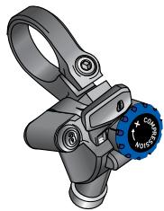
Compression Adjustment (Fig. 4)
Some fork models also feature adjustable compression damping. Increased compression decreases fork movement in the 'Open' position. Compression adjustment can be used to help combat brake dive and "squatting" under hard cornering.
For crown activated forks, compression damping increases to 'Lock' as the crown-mounted actuator rotates clockwise. Position the actuator anywhere within the range from 'Open' to 'Lock' to suit the desired level of compression damping.
Forks equipped with the PopLoc Adjust provide compression damping adjustment for the 'Open' position. Turning the blue adjuster on the PopLoc adjust clockwise increases compression damping for the 'Open' position. The PopLoc lever features gradients to help illustrate the current level of compression. Eight complete turns of adjustment are provided.
Tip: Adjusting compression on forks equipped with PopLoc Adjust is best done with the fork in 'Lock' position. Note: The compression setting does not adversely effect your fork's performance over high speed impacts.
Compression Range
Turning the compression adjuster on the PopLoc Adjust sets how far the lever returns from 'Lock' toward the 'Open' position. This adjustment changes the amount of compression damping found in the 'Open' position.
Remote Compression Adjuster
Crown mounted adjuster
PopLoc Adjust Remote
Fig. 4
MAINTENANCE
To maintain the high performance, safety, and long life of your fork, periodic maintenance is required. If you ride in extreme conditions, maintenance should be performed more frequently.
Note: We recommend this service be performed by a qualified bicycle mechanic. To obtain service information or instructions, visit our website at www.rockshox.com or contact your local RockShox dealer or distributor.
TORQUE TIGHTENING VALUES
| Top Caps | 65in - lb |
| Brake Posts | 80in - lb |
| Shaft Bolts | 60in - lb |
| PopLoc/Pushloc Remote handlebar clamp bolt | 20in - lb |
| Remote spool cable fixing bolt | 8in - lb |
| U-Turn knob and screw | 12in - lb |
SRAM CORPORATION WARRANTY
Extent of Limited Warranty
SRAM warrants its products to be free from defects in materials or workmanship for a period of two years after original purchase. This warranty only applies to the original owner and is not transferable. Claims under this warranty must be made through the retailer where the bicycle or the SRAM component was purchased. Original proof of purchase is required.
Local law
This warranty statement gives the customer specific legal rights. The customer may also have other rights which vary from state to state (USA), from province to province (Canada), and from country to country elsewhere in the world.
To the extent that this warranty statement is inconsistent with the local law, this warranty shall be deemed modified to be consistent with such law, under such local law, certain disclaimers and limitations of this warranty statement may apply to the customer. For example, some states in the United States of America, as well as some governments outside of the United States (including provinces in Canada) may:
a. Preclude the disclaimers and limitations of this warranty statement from limiting the statutory rights of the consumer (e.g. United Kingdom).
b. Otherwise restrict the ability of a manufacturer to enforce such disclaimers or limitations.
Limitations of Liability
To the extent allowed by local law, except for the obligations specifically set forth in this warranty statement. In no event Shall SRAM or its third party supplies be liable for direct, indirect, special, incidental, or consequential damages.
Limitations of Warranty
- This warranty does not apply to products that have not been incorrectly installed and/or adjusted according to the respective SRAM technical installation manual. The SRAM installation manuals can be found online at www.sram.com or www.rockshox.com.
- This warranty does not apply to damage to the product caused by a crash, impact, abuse of the product, non-compliance with manufacturers specifications of usage or any other circumstances in which the product has been subjected to forces or loads beyond its design.
-
This warranty does not apply when the product has been modified.
-
This warranty does not apply when the serial number or production code has been deliberately altered, defaced or removed.
- This warranty does not apply to normal wear and tear. SRAM does not include racing or competition as normal wear and tear. Wear and tear parts are subject to damage as a result of normal use, failure to service according to SRAM recommendations and/or riding or installation in conditions or applications other than recommended.
| SERVICE INTERVALS | DOMAIN | ARGYLE | REBA | REVELATION | PIKE |
| Inspect carbon crown-steerer | * | * | E | * | * |
| Clean dirt and debris from under tubs | E | E | E | E | E |
| Inspect upper tubes for scratches | E | E | E | E | E |
| Lubricate dust seals/tubes | 10 | 10 | 10 | 10 | 10 |
| Check top caps, brake posts and shaft bolts for proper torque | 25 | 25 | 25 | 25 | 25 |
| Check air pressure | * | E | E | E | E |
| Remove lowers, clean/inspect bushings and change oil bath | 50 | 50 | 50 | 50 | 50 |
| Change oil in damping system | 100 | 100 | 100 | 100 | 100 |
| Clean and lubricate Dual or Solo Air assembly | * | 50 | 50 | 50 | 50 |
| Clean and lubricate coil spring assembly | 100 | 100 | * | 100 | 100 |
Notes:
E = Every ride
Numeric values represent hours of Riding Time. Increase service intervals based on rider weight, aggressive riding style/conditions, inclement weather, and racing.
Wear and tear parts are identified as:
Dust seals
Bushings
Air sealing o-rings
Glide rings
Rubber moving parts
Foam rings
Rear shock mounting hardware and main seals
Upper tubes
- Stripped threads/bolts (aluminum, titanium, magnesium or steel)
Brake sleeves
o Brake pads
- Chains
Sprockets
Cassettes
- Shifter and brake cables (inner and outer)
Handlebar grips
° Shifter grips
Jockey wheels
Disc brake rotors
Tools
- This warranty shall not cover damages caused by the use of parts of different manufacturers.
- This warranty shall not cover damages caused by the use of parts that are not compatible, suitable and/or authorized by SRAM for use with SRAM components.

PKE
REACH
REVELATION
DAN
ARGYL
DUAL AIR (PIKE, REBA, REVELATION)
PIKE RE3A REVELATION DAAH ARGYL
DUAL AIR (PIKE, REBA, REVELATION)
PIKE RE3A REVELATION DAAH ARGYL
Part mobili in gomma
Anelli di schiuma
DUAL AIR (PIKE, REBA, REVELATION)
SRAM CORPORATION GARANTIE
PIKE RE3A REVELATION DAAH ARGYL
Regulacao do Floodgate
GARANTIA DA SRAM CORPORATION

- IMPORTANT
- CONSUMER SAFETY INFORMATION
- FORK INSTALLATION
- WARNING
- CARBON CROWN-STEERER INSTALLATION (Reba World Cup only)
- REMOTE INSTALLATION
- MAXLE 360° QUICK RELEASE SYSTEM
- INSTALLATION
- Tighten
- Secure
- PERFORMANCE TUNING
- SETTING SAG
- AIR SPRING TUNING
- DUAL AIR (PIKE, REBA, REVELATION)
- Step 1 - Selecting Positive Air Pressure
- Step 2 - Selecting Negative Air Pressure
- SOLO AIR (ARGYLE)
- Setting Solo Air:
- COIL SPRING TUNING
- Changing the Spring Rate
- TRAVEL ADJUSTMENTS
- Coil U-turn Travel Adjust (Domain, Pike, Revelation)
- Air U-Turn Travel Adjust (Pike, Revelation, Reba)
- Changing Travel (Argyle, Reba)
- REBOUND DAMPING
- External Rebound Adjustment
- 'Open' Compression (Fig. 1)
- Lock' Compression (Fig. 2)
- Floodgate Adjustment (Fig. 3) (Argyle 409, Pike, Revelation and Reba ONLY)
- Floodgate Adjustment
- All settings from Maximum Floodgate (or full clockwise)
- Compression Adjustment (Fig. 4)
- Compression Range
- MAINTENANCE
- SRAM CORPORATION WARRANTY
- Extent of Limited Warranty
- Local law
- Limitations of Liability
- Limitations of Warranty
- Notes:
- Wear and tear parts are identified as:
- PKE
- REACH
- REVELATION
- DAN
- ARGYL
- PIKE RE3A REVELATION DAAH ARGYL
- SRAM CORPORATION GARANTIE
- Regulacao do Floodgate
- GARANTIA DA SRAM CORPORATION
Brand : DAHON
Model : DOMAIN
Category : Folding bike