DX46 - Signal processor ELECTRO-VOICE - Free user manual and instructions
Find the device manual for free DX46 ELECTRO-VOICE in PDF.
| Product type | Digital signal processor (DSP) 2 inputs, 6 outputs |
| Brand | Electro-Voice |
| Model | DX46 |
| Dimensions (rack) | 1U (height), depth 353 mm (14 inches) |
| Weight | Approximately 4.5 kg (estimated) |
| Power supply | 100-240 V AC, 50-60 Hz, auto-ranging (IEC) |
| Power consumption | Fuse 5x20 mm, T800 mA, L250 V |
| Sampling frequency | 24 bits, 48 kHz |
| Inputs | 2 balanced XLR analog inputs, 1 AES/EBU digital input, Thru XLR connectors |
| Outputs | 6 balanced XLR outputs, each channel with limiter, crossover, EQ, delay |
| Main DSP functions | 10-band parametric EQ (input), 31-band graphic EQ (input), 512-tap FIR filters, multi-type crossover, delay up to 2 seconds, Peak/RMS limiter, test generator |
| Preset configurations | 7 configurations: 2-way stereo + FR, 3-way stereo, 4-way + FR, 5-way + FR, 3-way stereo with mono sub + FR, 4-way stereo with sub/LF, free configuration 2x6 |
| Preset memory | 60 factory presets, 30 user presets |
| Control and connectivity | Front panel USB port, Ethernet RJ-45 interface, Control port (5 contact inputs) |
| Control software | IRIS-Net (configuration, monitoring, firmware update) |
| Display | 192x32 backlit graphic LCD, LED VU meters |
| Operating temperature | 0°C to 40°C (estimated) |
| Maintenance and cleaning | Clean with a dry cloth. Do not block ventilation openings. |
| Safety | Code lock, warning: do not open, repair by qualified personnel, disconnect before servicing |
| Spare parts and repairability | Replaceable mains fuse, safety-marked parts must be original. Repair by authorized technician. |
Frequently Asked Questions - DX46 ELECTRO-VOICE
User questions about DX46 ELECTRO-VOICE
0 question about this device. Answer the ones you know or ask your own.
Ask a new question about this device
Download the instructions for your Signal processor in PDF format for free! Find your manual DX46 - ELECTRO-VOICE and take your electronic device back in hand. On this page are published all the documents necessary for the use of your device. DX46 by ELECTRO-VOICE.
USER MANUAL DX46 ELECTRO-VOICE
Dx46 Features 8
Unpacking & Warranty 9
IRIS-Net 10
Quick Start 10
Controls & Connection 13
Front Panel 13
Rear Panel 16
Installation 18
Setup 21
Setup Menus 21
Lock- Front Panel Access 25
Run time Mode 26
LCD Display 26
Level Meters 26
Output Gain Reduction Meters 27
Output Channel Mute Buttons 27
Output Channel Function Indicators 28
Presets Recall 28
Preset Store 29
Edit 29
DSP Parameters 30
- Configurations of the Dx46 39
2 Way Stereo + Full Range 40
3 Way Stereo 41
4 Way + FR 42
5 Way + FR 43
Free Configuration - Full Edit 2 In 6 Out 44
3 Way Stereo-MonoSub+FR 45
4 Way Stereo-MonoSub/LF 46
Operation Modes & Presets 48
Specifications 148
EQ Plot Images 151
Inhalt
Operation Modes & Presets 98
Specifications 148
EQ Plot Images 151
Sommaire
Presentation 102
Introduction 104
Setup (Configuration) 117
IMPORTANT SAFETY INSTRUCTIONS
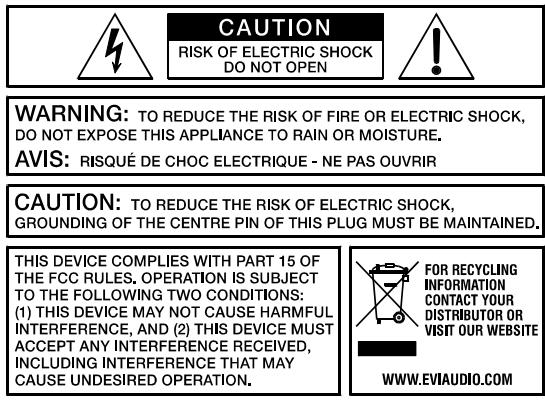

The lightning flash with arrowhead symbol, within an equilateral triangle is intended to alert the user to the presence of uninsulated "dangerous voltage" within the product's enclosure that may be of sufficient magnitude to constitute a risk of electric shock to persons.

The exclamation point within an equilateral triangle is intended to alert the user to the presence of important operating and maintenance (servicing) instructions in the literature accompanying the appliance.
- Read these instructions.
- Keep these instructions.
- Heed all warnings.
- Follow all instructions.
- Do not use this apparatus near water.
- Clean only with a dry cloth.
- Do not cover any ventilation openings. Install in accordance with the manufacturer's instructions.
- Do not install near heat sources such as radiators, heat registers, stoves, or other apparatus (including amplifiers) that produce heat.
- Do not defeat the safety purpose of the polarized or the grounding-type plug. A polarized plug has two blades with one wider than the other. A grounding type plug has two blades and a third grounding prong. The wide blade or the third prong are provided for your safety. If the provided plug does not fit into your outlet, consult an electrician for replacement of the obsolete outlet.
- Protect the power cord from being walked on or pinched particularly at plugs, convenience receptacles, and the point where they exit from the apparatus.
- Only use attachments/accessories specified by the manufacturer.
- Use only with the cart, tripod, bracket, or table specified by the manufacturer, or sold with the apparatus. When a cart is used, use caution when moving the cart/apparatus combination to avoid injury from tip-over.
- Unplug this apparatus during lightning storms or when unused for a long period of time.
- Refer all servicing to qualified service personnel. Servicing is required when the apparatus has been damaged in any way, such as power-supply cord or plug is damaged, liquid has been spilled or objects have fallen into the apparatus, the apparatus has been exposed to rain or moisture, does not operate normally, or has been dropped.
- Do not expose this equipment to dripping or splashing and ensure that no objects filled with liquids, such as vases, are placed on the equipment.
- To completely disconnect this equipment from the AC Mains, disconnect the power supply cord plug from the AC receptacle.
- The mains plug of the power supply cord shall remain readily operable.
- No naked flame sources, such as lighted candles, should be placed on the apparatus.
- The product should be connected to a mains socket outlet with a protective earthing connection.

IMPORTANT SERVICE INSTRUCTIONS
CAUTION: These servicing instructions are for use by qualified personnel only. To reduce the risk of electric shock, do not perform any servicing other than that contained in the Operating Instructions unless you are qualified to do so. Refer all servicing to qualified service personnel.
- Security regulations as stated in the EN 60065 (VDE 0860 / IEC 65) and the CSA E65 - 94 have to be obeyed when servicing the appliance.
- Use of a mains separator transformer is mandatory during maintenance while the appliance is opened, needs to be operated and is connected to the mains.
- Switch off the power before retrofitting any extensions, changing the mains voltage or the output voltage.
- The minimum distance between parts carrying mains voltage and any accessible metal piece (metal enclosure), respectively between the mains poles has to be 3mm and needs to be minded at all times. The minimum distance between parts carrying mains voltage and any switches or breakers that are not connected to the mains (secondary parts) has to be 6mm and needs to be minded at all times.
- Replacing special components that are marked in the circuit diagram using the security symbol (Note) is only permissible when using original parts.
- Altering the circuitry without prior consent or advice is not legitimate.
- Any work security regulations that are applicable at the locations where the appliance is being serviced have to be strictly obeyed. This applies also to any regulations about the work place itself.
- All instructions concerning the handling of MOS-circuits have to be observed.
NOTE:

SAFETY COMPONENT (MUST BE REPLACED BY ORIGINAL PART)
WEEE RECYCLING/DISPOSAL INSTRUCTIONS
The Wheelie Bin symbol found on the product or in the manual indicates that this product must not be disposed of with other waste. It is in our category the manufacturer's responsibility to properly dispose of their waste electrical and electronic equipment (WEEE) at the end of its life. Due to the differences in each EU country's management of WEEE, please contact your local distributor. We are committed to facilitate our own electronic-waste-management-system, for the free of charge return of all EVI Audio GmbH products: Telex, DYNACORD, Electro-Voice and RTS. Arrangements are made with the dealer where you purchased the equipment from, for the returning of all unusable equipment at no cost, to the factory in Straubing, for environmental protective disposal.
1 Overview
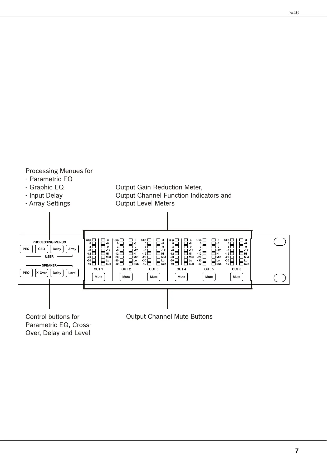
Processing Menues for
- Parametric EQ
- Graphic EQ
- Input Delay
- Array Settings
Output Gain Reduction Meter,
Output Channel Function Indicators and
Output Level Meters
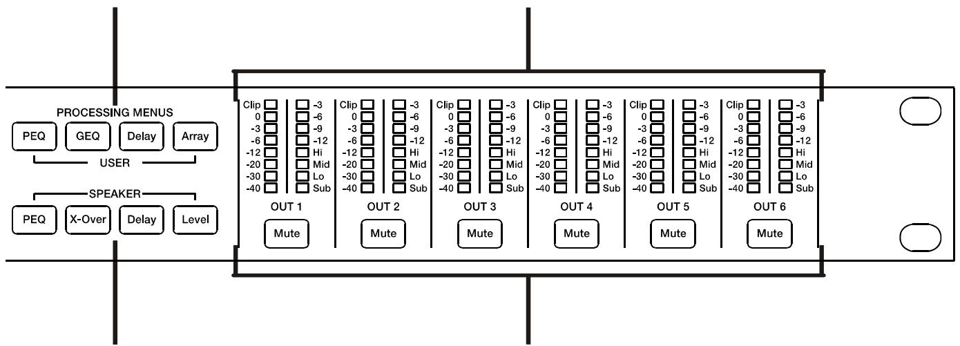
Control buttons for
Parametric EQ, Cross
Over, Delay and Level
Output Channel Mute Buttons
2 Introduction
Thank you for purchasing the Electro-Voice Dx46 Digital Signal Processor. The Dx46 Digital System Processor is a universal two-input, six-output digital signal processor with the flexibility of configuration to handle a multitude of audio system needs and applications; installed sound, house of worship, convention & meeting facilities, concert touring, club, portable sound reinforcement and more.
CAUTION: To achieve optimum performance and guard against damage to the processor, your sound system or yourself, please read, understand and follow all of the directions contained in this Owner's Manual. Failure to do so may result in improper performance, loss or injury.
2.1 Dx46 Features
The internal signal processing structure can be configured as 2-way stereo + full-range, 3-way stereo, 4-way mono + full-range, 5-way mono + full range, 3-way stereo with a mono sub + full-range, 4-way stereo with mono sub and low frequency and finally as a freely assignable 2 × 6 matrix router.
The Dx46 replaces entire racks of signal processors previously needed to properly configure and control sound reinforcement systems with a single Dual-Core DSP processor. The substantial advantages of the Dx46 over discrete signal processing racks include:
24-bit, 48 kHz digital signal path
No patch cables to fail or add noise
- Optimal gain structure throughout all stages of signal processing; no gain matching from processor to processor.
- Recallable factory and user presets; instant system reconfiguration for differing applications and performances.
- Easy, intuitive operation and editing with a PC and IRIS-Net
FIR-DRIVE
The Dx46 includes Finite Impulse Response (FIR) filters at each output for loudspeaker linearization. Using FIR filters has the following advantages, compared to using IIR filters (e.g. Bessel, Butterworth,...):
extremely linear frequency response
- very high stop-band attenuation
- linear phase systems
To sum up, FIR-DRIVE allows the linearization of frequency and phase of your Electro-Voice loudspeakers. Activating FIR-DRIVE is as easy as loading a FIR Speaker Setting in the output channel of the Dx46. The IRIS-Net software is used for loading Speaker Settings, and lots of Electro-Voice FIR Speaker Settings are included. Please refer to the documentation of IRIS-Net for more details about using Speaker Settings.
Each Dx46 Digital System Processor includes the following signal processing blocks:
INPUTS
- Pilot tone detection
VU Metering of input signal - Analog or digital (AES/EBU) inputs
24-bit, 48 kHz A/D converters
10-band parametric equalizer
31-band graphic equalizer
Delay
MATRIX ROUTER/MIXER
Two inputs (stereo)
Summed left / right (mono) input
Six assignable outputs
OUTPUTS (EACH)
- Array control (5-band equalizer +delay)
Cross-over (hi-pass / low-pass filters), with selectable filter types - 6-band parametric equalizer
FIR filter with 512 Taps
Delay - Polarity
- Look-ahead Peak limiter with Peak RMS detection
- TEMP Limiter for long-term loudspeaker protection
Level & Mute
24-bit, 48 kHz D/A converters - Pilot tone generator
VU Metering
Output assignment display LEDs; sub, low, mid & high - Mute button
Gain reduction meters
ADDITIONAL FEATURES INCLUDE:
- Electronically balanced XLR inputs and outputs
- XLR thru connectors (analog + AES/EBU)
-6 dB switchable input level pad
Test generator (Sine, pink noise, white noise) - Contact closure interface
- USB port (front) and Ethernet port (rear) for connection to PC with IRIS-Net software; preset editing and real time parameter control and monitoring.
- Firmware updates via USB port or Ethernet port
- FLASH memory for preset storage and firmware upgrades
192x32back-lightgraphicLCDdisplay - LCD navigation / editing controls
DSP block direct access controls - Auto-ranging internal power supply; 100-240 V AC, 50-60 Hz
- Standard IEC A.C. inlet with external, replaceable fuse
2.2 Unpacking & Warranty
Carefully remove the Dx46 from its packaging and packaging materials. Please save all packing materials and box, should you ever need to return the Dx46 for warranty service. Included with the Dx46 is this Owner's Manual, Warranty card and A.C. power cable. Contact your distributor, dealer or installer if any of these items is not included. Please save the warranty certificate and receipt; which must be presented at the time of warranty service for the factory warranty to be valid.
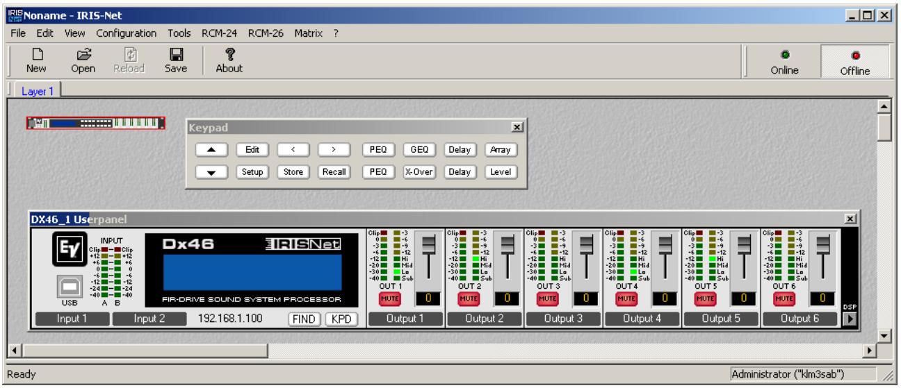
2.3 IRIS-Net
The IRIS-Net (Intelligent Remote & Integrated Supervision) PC software is used to configure and operate the Dx46. The configuration of the Dx46 can be done offline (i.e. without connection between the PC and the Dx46) on the PC. After the connection between the PC and the Dx46 has been established via Ethernet or USB, the configuration can be transmitted to it. In addition to configurations, IRIS-Net can also be used for extensive supervision, control and monitoring of the Dx46. The latest version of IRIS-Net is available at www.electro-voice.com.
2.4 Quick Start
CONNECT Dx46
Connect the signal inputs and outputs of the Dx46 (console - Dx46 - amplifier). You must make sure that each output is connected to the correct amplifier and loudspeaker(s). The Dx46 must be connected to A.C. power only by means of the provided IEC A.C. cable or by a power cable provided by the dealer / installer to match the configuration of your country or region. After power-up the number and name of the last loaded preset and the configuration mode is indicated.

RECALL PRESET
Press the Recall button and select the factory preset matching to your speaker configuration. Press the Recall button again to activate the preset. If the configuration of the Dx46 changes the Recall button has to be pressed a third time. The configuration LEDs indicate the function of each output channel. Full range is indicated by no lit LEDs.
Illustration 2-1: Output assignment LEDs
CAUTION: The parameter settings of the Dx46 factory presets are highly optimized and should not be changed. Especially editing the X-Over, PEQ or Limiter settings can result in damaged speakers.
The following steps are shown for one output channel only.
CONFIGURE LEVEL
Press the Level button to open the Level/Amp dialog.
OUT 1:Level/Limiter Level: 6.0dB Polarity:Inv Amp:User Gain:39dB
The Level parameter allows adjustment of the level ratio between sub and top speakers. E.g. if the parameters in a preset are optimized for 2 subs you can increase the sub level by 6 dB if you are using 1 sub in your application. As an alternative you can decrease the top level by 6 dB.
SELECT AMPLIFIER TYPE
Select the power amp type connected to the Dx46 using the parameter Amp. Please note there are multiple entries for an amplifier type if the amplifier allows different sensitivity settings.
OUT 1:Level/Limiter Level: 6.0dB Polarity:Inv Amp:TG-7 (O dBu)
If the amplifier type connected to the Dx46 is not included in the list, select the entry User. In this case you have to adjust the parameter Gain manually. Check the technical specification of your amplifier for the gain value.
OUT 1:Level/Limiter Level:6.0dB Polarity:Inv Amp:User Gain:39dB
If the correct gain value is unknown set the parameter Amp to Default. For this setting a gain of 39dB is used, this is sufficient for most amplifiers. By selecting the right amplifier type the limiter settings of the channel are adapted automatically, so the connected speakers are protected as required.
Ensure the level of the amplifier is set to 0dB to get the maximum power from the amps.
CONFIGURE DELAY
The Dx46 can be used to compensate for the positioning of cabinets or speaker arrays relative to each other or the original sound source.
Press the SPEAKER Delay button for adjusting one or more output channels and select Active in this dialog.
Select the preferred Unit (using cm as unit is recommended) and edit the setting of the parameter Delay.
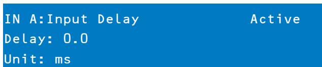
OUT 1:Output Delay Active
Delay: 7.0
Unit: ms
Setting the correct Delay value is important to avoid acoustic cancellation of signals. E.g. when using the two full-range channels of the configuration "2way + FR" as delay lines, the Delay of this two channels has to be adjusted according to the distance to the main PA.
If all connected speakers are used as a delay line, or the main PA should be moved acoustically "back to the stage", the input delay parameter of input channels A and/or B should be used in this cases. Press the USER Delay button to use the input delay, up to 2 seconds of delay are available for each input.
CONFIGURE EQUALIZER
Use the GEO (31 band) and PEQ (10 band) of each input channel for adjusting the sound of your system to your room characteristics. Press the USER PEQ or GEO button to open the equalizer dialogs.
IN A:PEQ1 Active
Type: Hipass F: 20000.0Hz
Slope: 12dB/0ct Q: 2.0
IN A:GEQ Detail
F:20Hz Gain:0.0dB Active
Type: Symmetric Q Q: 4.3
3 Controls & Connection
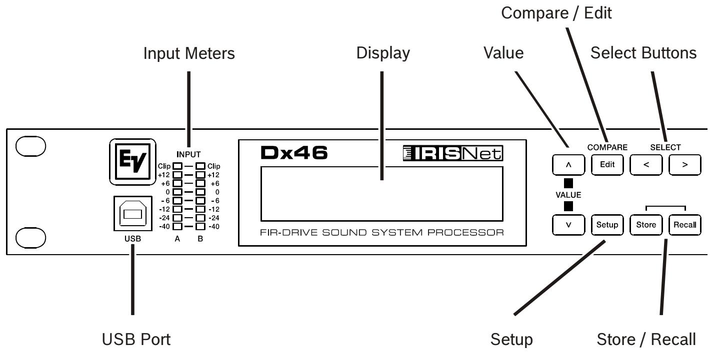
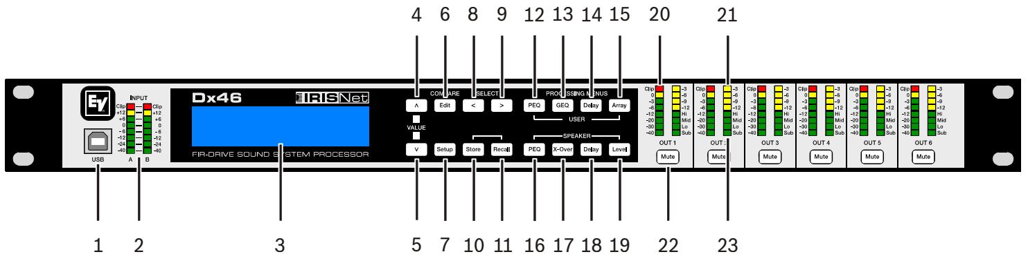
3.1 Front Panel
USB 1.1 port for connection to a PC running Windows XP, Vista or 7. With a connected PC you may run the IRIS-Net Application. The Dx46 can be operated, edited and configured with an easy to use, intuitive interface. Any available firmware updates downloadable from www.electro-voice.com can be loaded via the USB port as well; allowing for easy updates.
1 - USB CONNECTOR
2 - INPUT LEVEL METERS
The Dx46 does not itself have input level controls. Proper input level adjustment is accomplished by setting the output level from the (L / R) bus outputs from the connected mixer (or other audio output device), as the vast majority of today's mixer-outputs are dBu calibrated. When the mixer is operating at optimal levels, so is the Dx46. The input meters monitor the input level of either analog or AES-EBU inputs, depending on the input mode selection set in the Setup Menu. Optimal signal-to-noise performance is obtained when the nominal (average), input level consistently lights the +6dBu (green) and +12dBu (Yellow) LED indicators. As the Dx46 is a digital audio device – and digital clipping produces very unpleasant results, the Clip (red) LED should not light. If the Dx46's input does clip, reduce the output level of the connected mixer. The -6dB PAD can be used for adjusting the input level also.
3 - LCD DISPLAY
The back-lit, 192 × 32 graphic LCD display allows for operation and editing of the Dx46 without the need for an attached PC. The contrast can be set in the Setup Menu for varying lighting conditions and viewing angles. The LCD display works in conjunction with Menu buttons, < SELECT > buttons and VALUE up/down buttons - to operate, navigate and edit the Dx46's parameters. In Run mode, the LCD displays the number and name of the currently selected factory or user preset. Pressing the Recall or Store buttons switches to their respective menus. Pressing the Edit or Setup menu buttons switches the display to the last edited parameter.
In Edit and Setup mode, the top line of the LCD display shows the currently selected parameter edit screen. Use the < SELECT > buttons to activate the top line of the display, and the VALUE up/down buttons to scroll through available parameter edit screens.
4/5 - VALUE UP/DOWN BUTTONS
Depending on the current LCD screen, the VALUE up/down buttons performs the following function:
-
Recall - Select forwards/backwards through the stored preset list to select a preset to be recalled to current memory.
-
Store - Select User Preset destinations forwards/backwards to select a destination for the currently edited preset, scroll forwards through ANSI character set to name preset.
Edit / Setup - Scroll forwards/backwards through Edit / Setup screens when the top line of the LCD screen is active. Scroll forwards through values for the selected parameter in an Edit / Setup screen.
6 - EDIT / COMPAREBUZZONS
Pressing the Edit button while in Run mode places the current preset in Edit mode and the Edit button lights. The LCD display shows the last edit screen that was selected. From this point, any edit screen can be displayed and altered. Pressing the Edit button again "compares" the edited preset, if parameters have been altered, to the original un-edited preset. This compare function will audibly switch between the altered parameters and the previously stored settings, allowing you to hear the effect of any DSP changes that have been made. Use this feature to monitor progress in editing or creating presets. Subsequently recalling a new preset will prompt you to save changes, which you may do or not.
7 - SETUP BUTTON
Pressing the Setup button while in Run mode displays the Setup menus in the LCD display and the Setup button lights. In this mode, any Setup menu can be displayed and altered. Changes made to Setup menu items are saved automatically. To exit Setup mode, press the Setup button again. The LCD display will revert to Run mode.
8 - SELECT < BUTTON
The SELECT < button is pressed to navigate backwards through Edit, Setup and / or Recall menu displayed. The button cycles through all available value fields in a screen and wraps around from first to last.
9 - SELECT > BUTTON
The SELECT > button is pressed to navigate forwards through Edit, Setup and / or Recall menu displayed. The button cycles through all available value fields in a screen and wraps around from last to first.
10 - STORE BUTTON
Pressing the Store button while in Run mode displays the Store Preset screen in the LCD display and the Store button lights. In this screen edited presets can be named and saved to a user preset location. Pressing the Store button again completes the preset save operation. To exit without storing the current preset, press the Edit or Setup buttons to return to the Run mode screen.
11 - RECALL BUTTON
Pressing the Recall button while in Run mode displays the Recall Preset screen in the LCD display and the Recall button lights. In this screen, any of the 60 factory and 30 user presets can be recalled into current memory. Pressing the Recall button again completes the preset load operation and returns the LCD display to Run mode. To exit without storing the current preset, press the Edit or Setup buttons to return to the Run mode screen.
12 - USER PEQ BUTTON
Pressing the USER PEQ button places the current preset in Edit mode and jumps to the first screen of the parametric User Equalizer. Subsequent button presses toggle the display between Input A and Input B.
13 - USER GEO BUTTON
Pressing the USER GEO button places the current preset in Edit mode and jumps to the first screen of the graphic User Equalizer. Subsequent button presses toggle the display between Input A and Input B.
14 - USER DELAY BUTTON
Pressing the USER Delay button places the current preset in Edit mode and jumps to the User Delay screen. Subsequent button presses toggle the display between Input A and Input B.
15 - USER ARRAY BUTTON
Pressing the Array button places the current preset in Edit mode and jumps to the first Array screen. Subsequent button presses step through the available output channels (depending on configuration).
16 - SPEAKER PEQ BUTTON
Pressing the PEQ button places the current preset in Edit mode and jumps to the first SPEAKER Parametric Equalizer screen. Subsequent button presses step through the available output channels (depending on configuration).
17 - SPEAKER X-OVER BUTTON
Pressing the SPEAKER X-Over button places the current preset in Edit mode and jumps to the first Output Channel Cross-Over screen. Subsequent button presses step through the available output channels (depending on configuration).
Pressing the Delay button places the current preset in Edit mode and jumps to the SPEAKER Delay screen. Subsequent button presses step through the available output channels (depending on configuration).
Pressing the Level button places the current preset in Edit mode and jumps to the SPEAKER Level screen. Subsequent button presses step through the available output channels (depending on configuration).
Press and hold the SPEAKER Level button for 4 seconds to open the Limiter screen. Subsequent button presses step through the available output channels (depending on configuration).
20 - OUTPUT LEVEL METERS
Each output channel has an eight-segment output level VU meter. Meter response characteristics can be selected in the Setup menu:
Normal Fast,
Peak-Hold,
Slow Decay.
The yellow segment indicates that there is no headroom left to the selected VU reference i.E. D/A Converter Clip or Limiter Threshold. The red segments indicate clipping within the output signal path and should be avoided by adjusting the Output Level of the output channel. It is important to understand how the meters work and what they are displaying. The Output Meters are displayed as "dB to Limiter Threshold" or "dB to D/A clip". In other words, these meters will display the headroom between the output level and the limiter threshold or clip threshold of the D/A converter. When viewed in conjunction with the Gain Reduction meters, this provides a complete display of level and headroom before and after limiting has been engaged to allow system levels to be optimized. This also means that the output metering will be displayed differently depending on the limiter threshold setting.
21 - OUTPUT GAIN REDUCTION METERS
Each output channel has a four-segment gain reduction meter that shows the effect of the output channel Limiter on output signal; from -3dB to -12dB.
22 - OUTPUT CHANNEL MUTE BUTTONS
Each output channel has a lighted Mute button. Pressing the Mute button turns off the output of that channel. The button lights red as an alert. Press the Mute button again to restore the output channel's signal. Output channels may also be muted from IRIS-Net Application, if the unit is connected to a PC. Muting a channel in any window of the application will light the channel Mute button on the front panel of the unit as well.
23 - OUTPUT CHANNEL FUNCTION INDICATORS
Each output channel has a four-segment function display for informational purposes only. For any given configuration possible with the Dx46, an output channel may be identified as a sub, low, low/mid, mid, mid/hi, hi or full range output. One or two adjacent LED are displayed to indicate all possible output bandpasses. (Full range is indicated by no lit LED's.)
3.2 Rear Panel
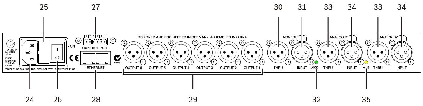
24 - A.C. INLET
The Dx46 features a standard IEC A.C. inlet that will accept universal power cords. The Dx46 power supply is autoranging and can accept voltages from 100 to 240V AC, 50 to 60Hz . Only A.C. cords approved for use in your country should be connected to the Dx46.
25 - A.C. Fuse
The A.C. inlet includes a fuse holder that contains the mains fuse as well as a spare fuse. If necessary, replace the fuse only with a specified 5x20mm, T800 mA, L250 V replacement. Disconnect A.C. power before replacing a fuse. Before turning the unit back on, assess the condition of the A.C. receptacle powering the Dx46. If fuses continue to blow, refer servicing of the Dx46 only to qualified service personnel.
26 - A.C. POWER SWITCH
The A.C. power switch turns power to the Dx46 On and Off.
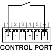
27 - CONTROL PORT
The CONTROL PORT of the Dx46 provides five control inputs and a reference connection for ground. The control inputs can be used for the recall of presets.
28 - ETHERNET INTERFACE
A computer and/or other ethernet devices (e.g. Dx46, NetMax N8000) can be connected via the Ethernet interface for 100Base-TX / 10Base-T Ethernet networks. Normally this connection is established via a standard (straight through) Ethernet cable and an Ethernet hub or a switch. The Dx46 can be connected directly with a computer or another Dx46 using a standard or crossover Ethernet cable.
29 - BALANCED XLR OUTPUTS
Each output channel has an electronically balanced XLR connector for connection to system amplifiers. Each output channel can output different frequency ranges depending on its assignment and cross-over settings.
CAUTION: Care must be taken to assure that each output is connected to an appropriate amplifier and loudspeaker to avoid damage or unexpected results. Note that a new preset may change the assignment of channel and its frequency range. For instance an output assigned to Hi frequency speakers in one preset, may be assigned as a sub output in another. See "Configurations of the Dx46".
30 - AES/EBU THRU PORT
The AES/EBU THRU port allows looping-through the digital audio signal to other devices. The digital input signal gets internally buffered and preprocessed (level matching / slew rate) before it is output via the THRU connector. This allows fairly simple wiring between devices, without the need for AES/EBU distribution amps as they are usually used. The Dx46 has a bypass-relay, which, in case of damage (e.g. power outage), connects the AES/EBU INPUT signal directly to AES/EBU THRU. This ensures trouble-free operation of downstream devices.
31 - AES/EBU INPUT
In addition to the analog audio inputs, an AES/EBU digital stereo input is provided and selectable in the Setup menu. The input conforms to IEC standard 60958 Type I. Connections must be made with three conductor, 110-Ohm, twisted pair cabling and an XLR connector. Digital audio signals in AES3 format with a sample rate from 32 kHz to 192 kHz can be connected. Please note that the maximum cable length depends on the sample rate.
32 - LOCK LED
The LOCK LED lights green as soon as the AES/EBU input has been synchronized to the incoming signal and thus proper audio transmission has been established. The LOCK LED is dimmed with no digital audio signal being present at the input or the internal PLL not having locked on to the incoming signal.
33 - BALANCED XLR THRU
Each analog audio input is connected to an electronically buffered and balanced output as a through connector. The signal does not run through any digital conversion or processing. These connectors are used to pass input audio to a second Dx46 used as a slave or to other audio inputs in the system.
34 - BALANCED XLR INPUT
Each input has an electronically balanced, locking XLR connector. In stereo or dual modes, connections to both inputs must be made. In mono modes, only one connection need be made, typically to Input A.
35 - 6dB LED
Input levels to the Dx46 can be reduced 6dB prior to the A/D converter to compensate for higher-level output from mixers and other audio devices. For ideal signal to noise performance when connecting the Dx46 to high output level devices engage the 6dB pad rather than turning down the output of the connected device. The Dx46's Input level Meters (2) will indicate incoming signal level and whether attenuation is required. This LED is permanently yellow when the 6dB pad is activated.
3.3 Installation
For proper operation, all directions regarding installation and connection must be followed.
MOUNTING
The Dx46 should be mounted in a rack-mount enclosure or rack rails. The unit is 1RU tall by 14" (353mm) deep. Proper clearance for air circulation around the unit must be provided. Do not block any vent holes on the unit. All four mounting points provided by the rack ears must be secured.
POWER CONNECTION
The Dx46 must be connected to A.C. power only by means of the provided IEC A.C. cable or by a power cable provided by the dealer / installer to match the configuration of your country or region. The Dx46 must only be connected to a properly wired, three pin, grounded A.C. outlet. A.C. power must range from 100 to 240 V AC, 50 to 60Hz. The Dx46 internal power supply is an auto-ranging design; no adjustments are necessary to configure it for proper A.C. power.
AUDIO CABLES (ANALOG)
Always use correctly shielded audio cables when connecting to the Dx46.
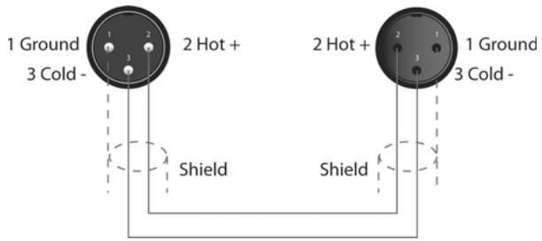
Balanced Input / Output Connections
To minimize induced noise caused by audio cables and to maximize the length of cables used, balanced connections are strongly advised for both Inputs and Outputs.
The XLR jacks provided on the Dx46 are configured as pin 1 ground, pin 2 hot (+), pin 3 cold (-). Cable shielding must be connected to pin 1. XLR - XLR cables or 14 "tip-ring-sleeve - XLR cables can both be used for balanced connections to the Dx46.
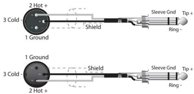
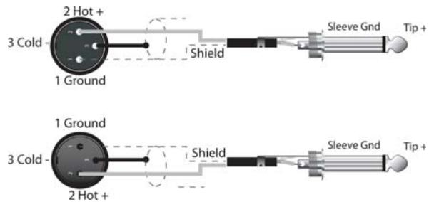
Un-balanced Input / Output Connections
Un-balanced connections can be made to the Dx46, although induced noise from cabling may be increased. Cables should also be less than 15^ (5 m) in length. Unbalanced connections can be 6dB lower in level as well. To match the audio level obtained with a balanced connection, it is necessary to tie pin 3 to ground at the XLR connector. This may increase noise.
AUDIO CABLE (AES/EBU)
A digital AES/EBU input (AES3) is provided in addition to the analog input. The digital input signal has to be connected to the AES/EBU INPUT connector. The AES/EBU input is a balanced transformer-isolated input. A sampling rate converter translates the input signal to match the internal sampling rate. The XLR jacks provided on the Dx46 are configured as pin 1 ground, pin 2 hot (+), pin 3 cold (-). Cable shielding must be connected to pin 1. XLR - XLR cables or 14 "tip-ring-sleeve - XLR cables can both be used for balanced connections to the Dx46.
HINT: Connections must be made with three conductor, 110-Ohm, twisted pair cabling.
ETHERNET
By connecting the Dx46 via the Ethernet interface, communication between the Dx46 and one or several PCs is possible. This allows the configuration of Dx46 via IRIS-Net software. The Ethernet interface on the rear of Dx46 is a RJ-45 connector (8P8C). Both 10Base-T and 100Base-TX Ethernet standards are supported.
Status LEDs
The status of the Ethernet interface is indicated by a orange and a green LED. If the Ethernet interface is not used both LEDs are off. The orange Link LED a the left side of the Ethernet interface lights, when the Dx46 has established a Ethernet connection to another device, e.g. another Dx46 or an Ethernet switch. The green network traffic LED at the right side of the Ethernet interface lights when sending or receiving a data packet.
CONTROL PORT
The CONTROL PORT of the Dx46 provides five control inputs and a reference connection for ground. The control inputs can be activated using external switches, pushbuttons or relays to connect them to ground potential, see following example.
USB PORT
Connecting the Dx46 to a PC for operation via IRIS-Net application can also be accomplished via the front panel USB port. The port conforms to the USB 1.1 Type B specification. Type B USB cables are readily available at computer dealers. According to USB specifications, the cable which is connected to this interface must not be longer than 15^ (5 meters). The USB interface of the Dx46 is a USB B (female) connector.
CONNECTION TO AMPLIFIERS
It is very important to confirm correct connection to all amplifiers. The Dx46 has the ability to configure each output for a specific frequency range; sub, low freq, mid freq, high freq. You must make sure that each output is connected to the correct amplifier and loudspeaker(s). Incorrect connections could lead to unexpected results or damage to loudspeaker components. Note also that each preset in the Dx46 includes DSP and bandpass parameters for the output channels. It is possible for a new preset to change an output from Hi to Sub, for instance. Make sure that connections to amplifiers and loudspeakers are correct before using a new preset.
INPUT LEVEL ADJUSTMENT
The final step in setting up, installing and connecting the Dx46 is to set proper input levels to the unit. The Dx46 does not itself have input level controls. Proper input level setting is accomplished by setting the output level from the (L / R) bus outputs from the connected mixer (or other audio output device). The input meters monitor the input level of either analog or AES/EBU inputs, depending on the input mode selection set in the Setup Menu. Optimal signal-to-noise performance is obtained when the nominal (average), input level consistently lights the +6dBu (green) and +12dBu (Yellow) LED indicators. As the Dx46 is a digital audio device – and digital clipping produces very unpleasant results – the Clip (red) LED should never light. If it does, reduce the output level of the connected mixer.
Input levels to the Dx46 can be reduced 6dB to compensate for higher-level output from mixers and other audio devices. For ideal signal to noise performance when connecting the Dx46 to high output level devices, engage the 6dB PAD rather than turning down the output of the connected device.
4 Setup
The Setup menu allows access Dx46's global parameters on the LCD screen. This is where preferences for many functions can be set or adjusted. Pressing the Setup button brings up the first Setup window. Use the VALUE up/down buttons to scroll through the Setup menu: Use the
CAUTION: To achieve optimum performance and guard against damage to the processor, your sound system or yourself, please read, understand and follow all of the directions contained in this Owner's Manual. Failure to do so may result in improper performance, loss or injury.
4.1 Setup Menus
NEW CONFIGURATION
The NEW CONFIGURATION window allows you creating a new, empty configuration for your system.
Setup: NEW CONFIGURATION Create new empty configuration Press 'Store' to continue
Press the Store button. Following dialog appears:
Destination Preset: U25
Name: Default User Preset 1
Press 'Store' to continue
Use the up/down VALUE up/down buttons to chose the Destination Preset (U01 to U30) for the empty configuration. Use the
Config: 3-Way StereoPress 'Store' to continue
Use the VALUE up/down buttons to choose between:
- 2 Way Stereo + FR
3 Way Stereo
4 Way + FR - 5 Way + FR
Free Configuration
3 Way Stereo-Mono Sub+FR
4 Way Stereo-Mono Sub/LF
See chapter Configurations on page 39 for more details. Press the Store button again to create the new configuration.
CAUTION: Before operating the sound reinforcement system, and any time a new preset is recalled, check the configuration display to make sure that it is appropriate for your system and that connections to your system are correct for the current configuration. Failure to do so could cause unexpected results or damage to the system or its components.
PRESET RECALL
The Dx46 allows the recall of presets by using external switches connected to the CONTROL PORT, see page 20. This window allows the assignment of Presets to the pins of the CONTROL PORT.
Setup: PRESET RECALL
Port(State): 1(1) 2(1) 3(1) 4(1) 5(1)
Preset: Off Off Off Off Off
Use the
The Control Port Contacts parameter is used as a display only and corresponds to the binary values of individual pins, ie - on/off.
SIGNAL GENERATOR

The integrated signal generator of the Dx46 can generate following signal types:
Sine signal
- White Noise
Pink Noise
This window allows editing the generated signal type and signal level for each input channel.
Setup: SIGNAL GENERATOR
Type: Sine Frequency: 1000Hz
A: Off -60.0dBu B: Off -60.0dBu
The selected type is always used for both input channels. The Frequency parameter is only available when Type: Sine is selected.
INPUT
This window is where the audio input can be configured.
Setup: INPUT Audio: Analog -6dB PAD: Off Gain A:0.0dB Gain B:0.0dB
Use the
For each of the two audio inputs a gain can independently be set (-60 dB to +12 dB). This can be useful if the level of two mono signals should be adjusted, without editing the presets.
DISPLAY
This window allows the user to adjust the contrast preferences of the LCD screen and the brightness of the front panel buttons to compensate for different lighting conditions that may be encountered within different venues. Additionally a screenshot can be activated.
Setup: DISPLAY Contrast: 0 Brightness: 1 Screensave: disable
Use the < SELECT > buttons to navigate to the Contrast parameter. Use the VALUE up/down buttons to choose between: -10 to +10 LCD contrast. Use the < SELECT > buttons to navigate to the Brightness parameter. Use the VALUE up/down buttons to edit the brightness of the buttons. Use the < SELECT > buttons to navigate to the Screensave parameter. Use the VALUE up/down buttons for enabling or disabling the screen saver.
FIRMWARE
This window displays the firmware version currently running on the Dx46.
Setup: FIMWARE Electro-Voice Dx46 V1.0.0
IP
This window displays the IP address and network mask of the Dx46.
Setup: IP Address:10.30.3.239 Mask:255.255.254.0
Use the < SELECT > buttons to navigate to the Address parameter. Use the VALUE up/down buttons to edit the IP address of the Dx46. Use the < SELECT > buttons to navigate to the Mask parameter. Use the VALUE up/down buttons to edit the subnet mask of the Dx46. Following table shows the default values of the ethernet interface.
Table 4-1: Default settings of the ethernet interface
| Parameter | Value |
| IP address | 192.168.1.100 |
| Subnet mask | 255.255.255.0 |
| Gateway | 192.168.1.1 |
DEVICE INFO
This window shows the on-time and the unique MAC addresses of the Dx46. The MAC address can not be changed.
Setup: DEVICE INFO
Ontime: 10days 00h 22m 07s
MAC-Address: 00-0b-7c-ff-fe-26
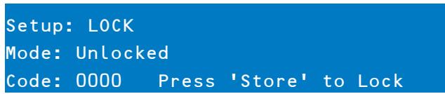
LOCK
This window allows locking the Dx46. Please see "Lock - Front Panel Access" on page 25 for details.
Setup: LOCK Mode: Unlocked Code: 0000 Press 'Store' to Lock
EDITING
This window allows selecting the edit mode (Standard or Full).
Setup: EDITING Edit Mode: Full Link: Off
The Dx46 defaults to Standard Edit mode wherein input and output channel parameters are appropriately linked. In Full Edit mode, no parameter links are enforced, regardless of the configuration selected. Use the < SELECT > buttons to navigate to the Edit Mode parameter. Use the VALUE up/down buttons to choose your editing preferences.
The Link, Id and Mask parameters (see following table) are used for linking parameters of Dx46 devices connected via Ethernet. Use the < SELECT > buttons to navigate to the Link, Id and Mask parameters. Use the VALUE up/ down buttons to edit the corresponding value.
Table 4-2: Default settings of the ethernet interface
| Parameter | Default | Description |
| Link | off | The link setting only works if more than one Dx46 device is connected to an ethernet. Devices that are Master or Slave have always identical parameter settings. Select „Master“, if this Dx46 should write the parameter settings to one or more other Dx46 (Slave). Select „Slave“, if the parameter settings of this Dx46 should be read from another Dx46 (master). Select „off“, if the parameter settings of this Dx46 should be independent from other devices. |
| Id | 0 | Each master Dx46 connected to the ethernet must have an unique network id. Enter the id of the Master Dx46 the parameters should be read from if this Dx46 is used as „Slave". |
| Mask | all groups selected | If the Link „Slave“ is selected, choose the parameter groups that this Dx46 should read from the Master Dx46. Following groups are available: • D: Parameters of the device • A or B: Parameters of input A or B • 1 to 6: Parameters of output 1 to 6 |
PARAMETER UNITS
This window allows selecting the unit used for temperature and the limiter threshold. Additionally the air temperature can be entered.
Setup: PARAMETER UNITS Temp: 68.0^ Units: Fahrenheit Limiter Threshold: dBu (DSP output)
The parameter Temp is used to calculate the speed of sound for converting delay times into distance. Use the < SELECT > buttons to navigate to the Temp and Units parameters. Use the VALUE up/down buttons to choose between -4.0 °F to +140.0 °F or -20 °C to +60 °C. The Units parameter lets the user choose between Fahrenheit and Celsius.
Use the < SELECT > buttons to navigate to the Limiter Threshold parameter. Use the VALUE up/down buttons to choose dBu (DSP output) or Vpk (Amp output).
Sound travels at different speeds depending on the density of the surrounding air it is traveling through. Cold air is denser than warm air thus, travels slower than it would if the air was warmer. Temperature can have a major influence with greater distances, particularly with respect to widely separated speaker arrays surrounding the audience for example. Temperatures might vary wildly between an indoor environment and an outdoor evening environment for example.
$$ V = 3 3 1 m / s + (0. 6 m / s / C) ^ {*} T $$
The speed of sound at room temperature is 346 meters per second. At freezing temperatures sound travels at 331 meters per second. V is the speed of sound and T is the temperature of the air. This formula finds the average speed of sound for any given temperature (celcius). The speed of sound is also affected by other factors such as humidity and air pressure.
METERING
Users can set their VU metering preferences here.
Setup: METERING
VU Mode: Peak hold
VU Reference: D/A Clip
Use the < SELECT > buttons to navigate to the VU Mode parameter. Use the VALUE up/down buttons to choose between Normal Fast, Peak Hold and Slow Decay. Use the < SELECT > buttons to navigate to the VU Reference parameter. Use the VALUE up/down buttons to choose between D/A Clip and Limiter Threshold.
4.2 Lock - Front Panel Access
A lockout mode has been provided for the installer to protect the system settings from being modified by a user. This can be set from the front panel or from the GUI software. Following table shows the different protection levels of the Dx46.
Table 4-3: Protection modes
| Mode | Description |
| GUI-Settable | One or more parameters of the Dx46 are locked via IRIS-Net and are not visible and/or editable via the front panel. |
| Panel and USB Locked | The buttons on the Dx46 front panel are locked. The device can be configured via IRIS-Net only. Connecting the Dx46 to the PC is possible via Ethernet only, the USB port is locked. |
| Panel Locked | The buttons on the Dx46 front panel are locked. The device can be configured via IRIS-Net only. Connecting the Dx46 to the PC is possible via Ethernet or USB. |
| Unlocked | All parameters can be configured via the Dx46 front panel or IRIS-Net. |
FROM THE FRONT PANEL
Press the Setup button and use the
Locking the Dx46
Use the < SELECT > buttons to navigate to the Mode parameter. Use the VALUE up/down buttons to choose the required protection mode. Use the < SELECT > buttons to navigate to the Code parameter. Use the VALUE up/ down buttons to choose your four digit code. Press the Store button to lock the Dx46.
Unlocking the Dx46
When the Dx46 is locked the Mode parameter indicates the currently used protection mode. Use the < SELECT > buttons to navigate to the Code parameter. Use the VALUE up/down buttons to enter the four digit code. Press the Store button to unlock the Dx46.
FROM IRIS-NET
Open the Dx46 dialog in IRIS-Net. Select the Front Panel Access tab. Any or all of the Dx46's DSP Blocks and/or individual parameters within the DSP blocks can be locked from this window by selecting the corresponding box to engage the lock icon or hidden by selecting the corresponding box to engage the eye icon. For example, an installer may chose to lock and hide all Limiter parameters, lock all Crossover parameters but leave them visible, and lock the last 5 Input PEQ filters, leaving the first 5 available for the user to edit and modify.
5 Run time Mode
5.1 LCD Display
On power-up, the Dx46 boots and displays the run-time screen. The current preset memory location and name are displayed as well as the configuration on which the preset is based.
Electro-Voice Dx46
U01 Default User Preset 1 FREE CONFIGURATION
CAUTION: Before operating the sound reinforcement system, and any time a new preset is recalled, check the configuration display to make sure that it is appropriate for your system and that connections to your system are correct for the current configuration. Failure to do so could cause unexpected results or damage to the system or its components.
The LCD display's contrast and button brightness can be adjusted in the Setup Menu (see page 22) to accommodate different viewing angles. Additionally a screensaver can be activated. The screensaver dims the brightness of the LEDs and buttons to 50% about 1 minute after the last action at the front panel. Additionally an floating EV logo is shown instead of the run-time screen.
Setup: DISPLAYContrast:0 Brightness:1Screensave: disable
5.2 Level Meters
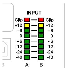
INPUT SIGNALS
During operation, the left and right input level meters display the signal present at the Dx46's analog and Digital inputs. The Dx46 does not itself have input level controls. Proper input level setting is accomplished by setting the output level from the (L / R) bus outputs from the connected mixer or other audio source. Optimal signal-to-noise performance is obtained when the nominal (average), input level consistently lights the +6dBu (green) and +12dBu (yellow) LED indicators. As the Dx46 is a digital audio device – and digital clipping produces very unpleasant results – the Clip (red) LED should never light. If it does, reduce the output level of the connected mixer. The -6dB PAD can be used for adjusting the input level also.
Illustration 5-1: Level meters of input channels
OUTPUT SIGNALS
Each output channel has an eight-segment output level VU meter. Meter response characteristics can be selected in the Setup menu:
Normal fast
Peak Hold
Slow decay.
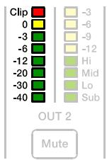
Illustration 5-2: Level meters of output channel
The yellow segment indicates that limiting is being applied to the output channel. It is important to understand how the meters work and what they are displaying. The Output Meters are displayed as "dB to Limiter Threshold" or "dB to D/A clip". In other words, these meters will display the headroom between the output level and the limiter threshold or clip threshold of the D/A converter. When viewed in conjunction with the Gain Reduction meters, this provides a complete display of level and headroom before and after limiting has been engaged to allow system levels to be optimized. This also means that the output metering will be displayed differently depending on the limiter threshold setting. The red segments indicate clipping of the output signal and should be avoided by adjusting the Output Level setting of the output channel.
5.3 Output Gain Reduction Meters
Each output channel has a four-segment gain reduction meter that shows the effect of the output channel Limiter on output signal; from -3dB to -12dB. Output limiting can be bypassed by entering Edit mode, selecting Output Channel Limiter and selecting the Bypass parameter.
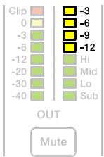
Illustration 5-3: Gain Reduction meter of output channel
5.4 Output Channel Mute Buttons
Each output channel has a lighted Mute button . Pressing the Mute button turns off the output of that channel. The button lights red as an alert. Press the Mute button again to restore the output channel's signal.
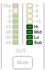
5.5 Output Channel Function Indicators
Each output channel has a four-segment function display for informational purposes only. For any given configuration possible with the Dx46, an output channel may be identified as a sub, low, low/mid, mid, mid/hi, hi or full range output. One or two adjacent LED's are displayed to indicate all possible output bandpasses. (Full range is indicated by no lit LED's.)
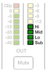
Illustration 5-4: Output channel function indicator
5.6 Presets Recall
The Dx46 preset memory provides 60 factory presets and can store up to 30 user presets (F01 to F60, U01 to U30). Factory presets have been designed to represent common system configurations utilizing Electro-Voice loudspeaker systems. User presets allow you to accommodate other system configurations and / or loudspeaker systems. To recall a preset, press the front panel Recall button. The display switches to the Recall Preset screen and displays the next in a list of available presets in memory.
Recall Preset: U01
Name: Default User Preset 1
Press 'Recall' to continue
Using the Value Up and Down buttons, select the preset to be recalled and press Recall again. The display will prompt, "Press ,Recall' to load"
Press 'Recall' to load Any other key to cancel
Press Recall a third time to confirm and load the new preset. If the preset you are recalling is based on a configuration different from that of the current preset, the display will prompt, "Changing config can damage speakers", to remind you that the new preset may not be appropriate for your system as it is currently connected. Press Recall again to confirm and load the new preset.
CAUTION: Make sure that the new preset is appropriate for your system, and that connections to your system are correct for the current configuration. Failure to do so could cause unexpected results or damage to the system or its components.
To exit the Recall process without loading a new preset, press the Edit, Setup or any of the DSP block buttons. (Edit or Setup buttons will return the display to run-time mode. DSP block buttons will display the corresponding DSP block edit screen.)
5.7 Preset Store
Edited presets can be stored in one of 30 User Preset locations. (U01 to U30) To store a preset, press the button. The LCD display will switch to the Store Preset screen.

Store Preset: U01
Name: Default User Preset 1
Press 'Store' to continue
Use the Value Up and Down buttons to select the user destination. Press the < SELECT > buttons to navigate down to the preset name field. Use the Value Up and Down buttons to select the field for each letter / symbol character. The Dx46 provides the complete ANSI character set, including lower-case & upper-case letters, numerals and symbols. Pressing and holding the Value Up and Down buttons will scroll rapidly through the character set. Press the < SELECT > buttons to move to the next or previous character position. Finish the name editing by pressing the Store button. The display shows "Save Edits? Hit ,Store" or "Save Unedited? Hit ,Store".
Save Edits? Hit 'Store' Any other key to cancel
Press Store again to proceed and store the new preset.
To Exit Store without saving the edited preset, press the Edit, Setup or any of the DSP block buttons. (Edit or Setup buttons will return the display to run-time mode. DSP block buttons will display the corresponding DSP block edit screen.)
5.8 Edit
Both Factory and User presets can be edited, but edited presets can only be stored in User preset locations.
STANDARD EDIT MODE
The Dx46 defaults to Standard Edit mode wherein, input and output channel parameters are appropriately linked.
Setup: EDITING Edit Mode: Standard Link: Off
Refer to the illustrations in chapter "Configurations of the Dx46" on page 39 to see which channels are parameter-linked for each configuration. Linked parameters are always identical in value. For instance, setting a graphic eq curve for Input A, sets the same curve for Input B, if the configuration has linked stereo inputs. Either input channel can be edited; changes will be reflected in both. The same is true for parameters of linked output channels. The only exception to the linking of parameters is the Mute buttons. Output channels can be individually muted at any time, either from the Dx46 front panel or the IRIS-Net application.
FULL EDIT MODE
In the Setup EDITING menu, the edit mode can be changed to Full. In Full Edit, no parameter links are enforced, regardless of the configuration selected. Any parameter can be changed without any effect on other parameter values.
Setup: EDITING Edit Mode: Full Link: Off
Regardless of the edit mode selected, there are two means to enter edit mode: pressing the Edit button or pressing any DSP block button. Use the < SELECT > buttons to navigate to the top line of any edit screen, and the Value Up and Down buttons to navigate to any other Edit screen. As a short-cut, press a DSP block button to jump to the last selected screen of said block and navigate as above to reach the desired screen.
5.9 DSP Parameters
The following section is a detailed description of every DSP parameter available in the Dx46; grouped by DSP block, in order of the signal flow of the Dx46.

Illustration 5-5: DSP blocks of input A or B
INPUT LEVEL

SIGNAL

PEQ

GEQ

DELAY
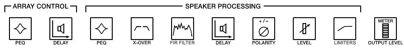
Illustration 5-6: DSP blocks of outputs 1 to 6
Not all parameters may be accessible in every preset and, depending on the configurations set by the contractor/ installer, not all presets and/or preset values may be available for editing. Changes to preset availability, parameter availability and preset value ranges can only be set using the IRIS-Net application.
WHY ARE THERE SO MANY DIFFERENT DELAY SECTIONS?
When configuring a PA or loudspeaker system, there are a variety of different scenarios that will require time alignment or delay compensation. Some of the different scenarios are:
- Delaying a set of loudspeakers to act as under-balcony fills or delay towers in a concert PA
- Aligning a PA system to the sound source on a stage, or aligning the "tops" to the "subs"
- Timing correction to compensate for the offset acoustic centers of individual transducers within a loudspeaker cabinet
- Delay offset for one or more loudspeakers in a cluster to improve coverage and overlap effects
Some applications will only encounter a few of these needs, while others will encounter all of them, such as in a theater with a center cluster of horn-loaded loudspeakers, subwoofoers, and under balcony delay speakers.
With other DSP products, a designer must make use of only one or two delay sections, which means that a designer must carefully think about how to calculate delays, how to add offsets to individual channels so that delay section can perform multiple tasks. This can result in a confusing DSP structure and more potential for delays being adjusted improperly. The Dx46 provides dedicated delay sections to perform each of these delay scenarios independently, which provides easier setup, adjustment and programming.
SIGNAL GENERATOR

The integrated signal generator of the Dx46 can generate following signal types:
- Sine signal
White Noise
Pink Noise
Please refer to page 22 for details.
INPUT PARAMETRIC EQ (PEQ)

PEQ
Use the < SELECT > buttons to make the top line of the Edit screen active and the Value Up and Down buttons to navigate to the Input PEQ screen. The Dx46 provides a stereo 10-band multi-mode filter generically referred to as the Input PEQ (Parametric Equalizer).
| IN A:PEQ1 | Active |
| Type: Hipass | F: 20000.0Hz |
| Slope: 12dB/oct | Q: 2.0 |
The Input PEQ is a very powerful and complex set of multi-mode filters. Care must be given configuring these filter bands, as they interact and can produce unexpected results. Using the IRIS-Net application is strongly recommended to set all but the most simple eq curves.
Each band of the Input PEQ can be configured for a specific filter type, frequency, slope or Q and gain setting. Attention must be paid to the ultimate output gain through the rest of the Dx46's audio path, as it is possible to boost frequency ranges to the point where the internal or external audio paths of the system may be clipped. Monitoring the output VU meters of the Dx46's output channels will indicate internal clipping; the input meters of connected amplifiers should do the same. The following section details the type of filters that can be selected for each of the Input PEQ's 10 bands and their parameters.
Table 5-7: Input Channel Parametric EQ
| Filter type | Frequency | Slope | Resp / Q | Gain |
| Loshelv | 20 to 20000 Hz | 6dB/oct. | - | -18.0 to +12.0 dB |
| 12dB/oct. | ||||
| Hishelv | 6dB/oct. | - | ||
| 12dB/oct. | ||||
| PEQ | - | 0.40 to 40 | ||
| Lopass | 6dB/oct. | - | - | |
| 12dB/oct. | 0.4 to 2.0 | - | ||
| Hipass |
Low shelf (Loshelv)
The Low-shelf filter is a "hinge" type; in that frequencies below its frequency setting can be boosted or cut; hinging on the cut-off Frequency. The amount of boost or cut (Gain), and the extent of width of the filter's transition band (Slope), are determined by the low-shelf filter's settings. (See Response/Q and Gain.) Use the < SELECT > buttons to navigate to the filter setting you wish to adjust, and the Value Up and Down buttons to alter these settings. Press the Value Up and Down buttons once to increment values by one unit, or press and hold to scroll rapidly through available values. (Values do not wrap around.)
Hi shelf (Hishelv)
The Hi-shelf filter is a "hinge" type; in that frequencies above its frequency setting can be boosted or cut; hinging on the cut-off Frequency. The amount of boost or cut (Gain), and the width of the filter's transition band (Slope), are determined by the hi-shelf filter's settings. (See Response/Q and Gain.) Use the < SELECT > buttons to navigate to the filter setting you wish to adjust, and the Value Up and Down buttons to alter these settings. Press the Value Up and Down buttons once to increment values by one unit, or press and hold to scroll rapidly through available values. (Values do not wrap-around.)
PEQ
PEQ is shorthand for Parametric Equalizer. A parametric equalizer has three parameters that determine the frequencies that are affected by it; Center Frequency, Q (filter-width) and Gain. Parametric filters are ideal for identifying, isolating and correcting problematic frequency ranges. The Frequency parameter determines the center of a range of frequencies that will be adjusted by the PEQ. The Q parameter will determine the range of frequencies adjacent to the center frequency that will also be effected; the greater the value, the smaller the range of adjacent frequencies that will be effected. The gain parameter determines the amount of boost or cut that is applied to the frequencies
that are affected by the filter. Use the < SELECT > buttons to navigate to the filter setting you wish to adjust, and the Value Up and Down buttons to alter these settings. Press the Value Up and Down buttons once to increment values by one unit, or press and hold to scroll rapidly through available values. (Values do not wrap-around.)
Low-pass (Lopass)
The Low-Pass filter determines the ultimate high frequency that your sound reinforcement system is allowed to reproduce; given the capabilities of amplifiers, speakers and transducers. The low-pass filter is useful for reducing excessive high frequency energy that can create stress on high frequency transducers and listener fatigue. Available parameters are Frequency and Slope. The frequency parameter determines the frequency above which frequencies will be attenuated. The slope determines how quickly frequencies above the cutoff frequency will be attenuated. (See response curve.)
Use the < SELECT > buttons to navigate to the filter setting you wish to adjust, and the Value Up and Down buttons to alter these settings. Press the Value Up and Down buttons once to increment values by one unit, or press and hold to scroll rapidly through available values. (Values do not wrap-around.)
High-pass (Hipass)
The Hi-Pass filter determines the ultimate low frequency that your sound reinforcement system is allowed to reproduce; given the capabilities of amplifiers, speakers and transducers. Available parameters are Frequency and Slope. The frequency parameter determines the frequency below which frequencies will be attenuated. The slope determines how quickly frequencies below that will be attenuated. (See response curve.) Use the < SELECT > buttons to navigate to the filter setting you wish to adjust, and the Value Up and Down buttons to alter these settings. Press the Value Up and Down buttons once to increment values by one unit, or press and hold to scroll rapidly through available values. (Values do not wrap-around.)
INPUT GRAPHIC EQ (GEQ)
Use the < SELECT > buttons to make the top line of the Edit screen active and the Value Up and Down buttons to navigate to the Input GEO screen. The Dx46's input signal path includes a stereo 31-band graphic equalizer after the stereo 10-band PEQ in the signal path. This DSP block can be used for very precisely identifying, isolating and correcting problematic frequency ranges. Keep in mind that changes
to the Input GEQ will be interactive with adjustments made in the Input PEQ. Unexpected results can occur.
Overview
Press the < SELECT > buttons to move the cursor down into the GEQ frequency adjustment field. Subsequent presses of the < SELECT > buttons will move the cursor forward or backwards through the frequency adjustment field; from band to band. The selected frequency's "fader" is highlighted in the display. As each band is selected, its center frequency and current cut/boost setting is displayed on the top line of the LCD display.

To adjust the amount of boost or cut for a selected frequency band, select the band with the < SELECT > buttons and press the Value Up or Down buttons as required. The LCD display will reflect your changes by moving the selected frequency band's "fader" up or down.
Table 5-8: Fader in GEO
| Fader | Description |
| Fader active (Active) | |
| Fader deactivated (Bypass) |
Detail
Use the < SELECT > buttons to navigate to the filter setting (see table below) you wish to adjust, and the Value Up and Down buttons to alter these settings.
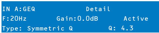
Table 5-9: GEO band parameters
| Parameter | Description |
| Frequency (F) | Select frequency band |
| Gain | The amount of boost or cut (-12.0 to +12.0 dB) |
| Active/Bypass | Select Active to activate the filter. Select Bypass to deactivate the filter. |
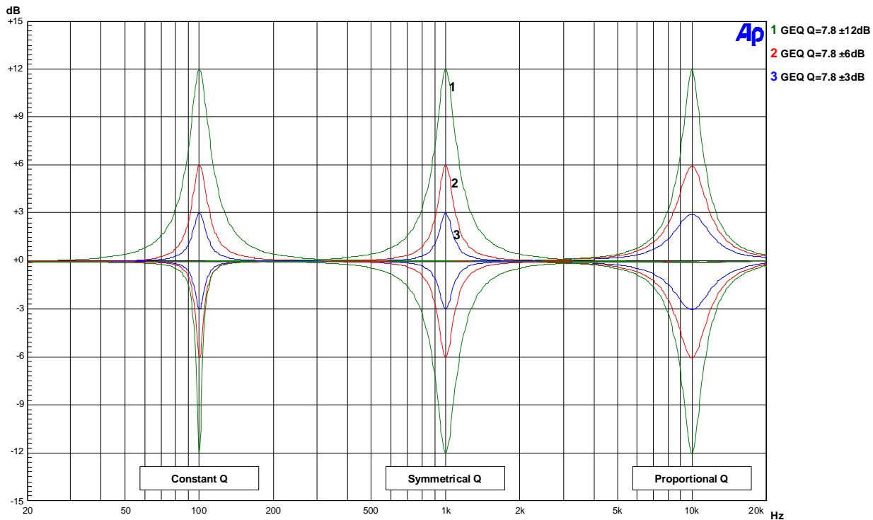
| Type | Following filter types are available: • Symmetric Q • Proportional Q • Constant Q |
| Quality (Q) | Quality of the filter |
To exit the Input GEO edit screen, press the Input GEO button, use the
INPUT DELAY

DELAY
The Dx46 offers an input delay that is useful for compensating for different arrival times of sound originating from loudspeakers that are closer or further away from the listener than others. A technique known as the Haas Effect allows the operator to create the illusion that all of the sound has originated from the stage even though additional speakers have been placed around the room.
HINT: The Input Delay parameter is especially useful for delay lines. In this case the required delay, depends only on the position of the delay line and is identical for all ways, e.g. output channels of the Dx46. By editing the Input Delay parameter the delays of all output channels routed to this input are adjusted automatically.
Available Input Delay parameters are Delay, Units and Active/Bypass. The Delay parameter allows the user to determine the Delay time values and the Active/Bypass parameter to activate or deactivate the delay.
To access the Input Delay, press the Delay button found on the input processing menu. Subsequent button presses will toggle the display between Input A and Input B. Input delay parameters are accessed using the
Table 5-10: Units of input delay
| Unit | Description |
| sec | seconds |
| ms | milliseconds |
| μs | microseconds |
| samples | samples |
| feet | feet |
| inch | inch |
| meter | meters |
| cm | centimeters |
ROUTING
Input selections (In-A, In-B or In-A+B) can be applied to any or all of Dx46's six outputs. Choose a desired output channel from the output menu and press the Edit button to scroll to the Routing window using the Value up/down arrows.
OUT 1:Routing
Source: In B
Using the
ARRAY PARAMETRIC EQ

Use the < SELECT > buttons to make the top line of the Edit screen active and the Value Up and Down buttons to navigate to the Array Eq screen. In the ARRAY CONTROL section an 5-band parametric equalizer is available for each output.
OUT 1:Array PEQ1 Active
Type: PEQ F:30.0Hz
Q: 0.7 Gain: 1.0dB
Use the < SELECT > buttons to navigate to the filter setting (see table below) you wish to adjust, and the Value Up and Down buttons to alter these settings. Press the Value Up and Down buttons once to increment values by one unit, or press and hold to scroll rapidly through available values.
Table 5-11: Array Control EQ
| Type | Frequency | Slope / Order | Resp / Q | Gain |
| Loshelv | 20 to 20000 Hz | 6dB/oct. | - | -18.0 to +12.0 dB |
| 12dB/oct. | ||||
| Hishelv | 6dB/oct. | - | ||
| 12dB/oct. | ||||
| PEQ | - | 0.40 to 40 | ||
| Lopass | 6dB/oct. | - | - | |
| 12dB/oct. | 0.4 to 2.0 | - | ||
| Hipass | ||||
| Allpass | 1 | - | - | |
| 2 | 0.4 to 2.0 |
ARRAY DELAY
Use the < SELECT > buttons to make the top line of the Edit screen active and the Value Up and Down buttons to navigate to the Array Delay screen. In the ARRAY CONTROL section a delay is available for each output.
HINT: The Array Delay parameter can be used for adjusting the individual cabinets within a loudspeaker cluster, such as a subwoofer array or a center loudspeaker cluster. For example, in a speaker cluster consisting of two horn-loaded loudspeakers, it is helpful to apply 3-5 mS of delay to one of the loudspeakers in the cluster to improve the coverage in the overlap of the horn patterns. Additionally, the array delay provides a convenient section to apply dedicated delay to individual subwoofer cabinets to create gradient or beam-formed arrays.
OUT 1:Array Delay Active
Delay: 7.0
Unit: ms
Use the < SELECT > buttons to navigate to the delay setting you wish to adjust, and the Value Up and Down buttons to alter these settings.
OUTPUT PARAMETRIC EQ (PEQ)

PEQ
Pressing the PEQ button places the current preset in Edit mode and jumps the LCD screen to a pre-selected parametric EQ (bands 1-6). Subsequent button presses advances the display to the next output channel (OUT1 to OUT6). Use the
| OUT 1:PEQ1 | Active |
| Type: PEQ | F:30.0Hz |
| Q: 0.7 | Gain: 1.0dB |
Adjust the values of each parameter using the up/down VALUE arrows.
Table 5-12: Parametric EQ
| Filter type | Frequency | Slope / Order | Resp / Q | Gain |
| Loshelv | 20 to 20000 Hz | 6dB/oct. | - | -12.0 to +18.0 dB |
| 12dB/oct. | ||||
| Hishelv | 6dB/oct. | - | ||
| 12dB/oct. | ||||
| PEQ | - | 0.40 to 40 | ||
| Lopass | 6dB/oct. | - | - | |
| 12dB/oct. | 0.4 to 2.0 | - | ||
| Hipass | 1 | - | - | |
| 2 | 0.4 to 2.0 | |||
| Allpass | 1 | - | - | |
| 2 | 0.4 to 2.0 |
OUTPUT X-OVER

X-OVER
The Dx46's crossover is an advanced frequency division process that is accomplished by applying a variety of high-pass and low-pass filters to a predetermined set of crossover points. Speaker systems are generally made up of several drivers that are dedicated to a specific range of frequencies that result in the efficient reproduction of the audio spectrum and a smooth sound. The Dx46 crossover routes frequencies to the appropriate drivers to accurately reproduce sound. The crossover network can also be sure that low-frequency energy is not accidentally routed to the mid-range or tweeter drivers that may result in damage. Available Dx46 crossover parameters are Type and Frequency.

To access the Crossover screen, press the X-Over button. Subsequent button presses will toggle the display between OUT1 to OUT6. Use the Value Up and Down buttons to navigate between the X-Over HIPass, X-Over Lopass, X-Over Delay and FIR Filter screens.
| OUT 1:X-Over Hipass Type:12dB Butterworth F:80.0Hz Trim:3.0dB |
The Dx46 Crossover offers a variety of Hipass and Lopass filters depending on the configuration output selected along with a variety of selectable filters and frequency ranges that are adjustable using the up/down VALUE arrows.
Table 5-13: Crossover parameters
| Parameter | Description |
| Type | Type offers list of selectable slopes/response Q's • Thru • 6dB • 12dB, Q = 0.5 to 2.0 • Bessel: 12 dB, 18 dB or 24 dB • Butterworth: 12dB, 18dB or 24 dB • Linkwitz-Riley: 12dB or 24 dB |
| Frequency | Frequency offers a selectable frequency range from 20 to 20000 Hz. |
| Trim | The amount of boost or cut |
Hi-Pass/Lo-Pass
The Dx46 Hi-Pass and Lo-Pass filters are determined by selecting the Type from the list of parameters, (see list above) and by choosing a frequency range between 20.0 Hz to 20,000Hz. (See above). Additionally the Trim parameter can be used.
The crossover filter generally consists of a low pass filter in one channel and a high pass filter in the adjacent channel. This is where the frequency x -over filter's Hi-Pass parameters are set. The Hi-Pass frequency parameters are linked to the corresponding Lo-Pass frequency parameter unless in Full Edit Mode or using the Free Configuration option. Please refer to the Configuration section of this manual for details on the effect different Configurations have on channel linking. The Type parameter defines the filter characteristics of the crossover Hi-Pass filter. Different slopes and filter responses (6dB, 12dB with different Q values, Bessel, Butterworth, Linkwitz-Riley) are available. Again, the Hi-Pass frequency parameters are linked to the corresponding Lo-Pass frequency parameter depending on the Configuration that is currently being used. High pass frequencies are set with a pre-determined frequency that attenuates frequencies below (the crossover point). On the contrary, a Low Pass filter passes frequencies below the crossover point and attenuates those above.
Crossover Alignment Delay
To access the X-Over Delay screen, press the X-Over button found on the output processing menu. Subsequent button presses will toggle the display between OUT 1 to OUT 6. Use the Value Up and Down buttons to select the X-Over Delay screen.
HINT: The X-Over Delay parameter is used for the alignment of transducers within cabinets. Optimized delay values are included in Electro-Voice Speaker Settings and should not be edited.
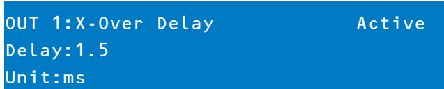
Use the
Table 5-14: X-Over Delay parameters
| Parameter | Description |
| Delay | Use this parameter to compensate for physical offsets of the acoustic centers of transducers within a loudspeaker cabinet. For example, due to cabinet construction, the acoustic center of a high frequency transducer may be mounted behind or in front of the acoustic center of the low frequency transducer. The Delay parameter can align the audio signal between the multiple transducers within the loudspeaker. |
| Unit | The user may select between time and distance display. Distances are automatically converted into delay times. This calculation also includes the influence of the environmental temperature based on the Temperature parameter in the Setup Menu. |
| Active/Bypass | Setting this to Bypass disables the Crossover Delay. |
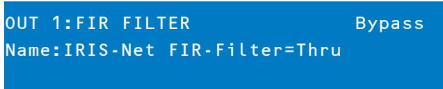
FIR FILTER
To access the FIR FILTER screen, press the X-Over button found on the output processing menu. Subsequent button presses will toggle the display between OUT 1 to OUT 6. Use the Value Up and Down buttons to select the FIR FILTER screen. The FIR FILTER screen shows the Name of the currently used FIR filter.
Use the
OUTPUT DELAY

To access the Delay screen, press the SPEAKER Delay button. Subsequent button presses will toggle the display between OUT 1 to OUT 6.
HINT: The Dx46's output delays can be used to compensate for the positioning of cabinets or speaker arrays relative to each other or the original sound source, for example aligning the PA to the stage or aligning the full-range loudspeakers to the subwoofoers. The Output Delay parameter determines the delay time of the corresponding channel or the distance between different loudspeaker clusters.
OUT 1:Output Delay Active Delay:7.0 Unit:ms
Use the
OUTPUT LEVEL

The Output Level is used to adjust master output levels. To access the Output Level screen, press the Level button. Subsequent button presses will toggle the display between OUT 1 to OUT 6.
OUT 1:Level/Limiter
Level: 6.0dB Polarity:Inv
Amp: TG-7 (0 dBu)
Use the
Limiter threshold values are determined by the amplifiers and loudspeakers that are used in the system. One important consideration in setting the limiter threshold value is the input sensitivity and gain of the connected amplifiers. Because different amplifiers can have different sensitivities, it is common to need to calculate the limiter offset to a factory preset based on the amplifier sensitivity. The Dx46 offers a unique solution to this problem with the Amp parameter. All Dx46 Factory Presets include limiter threshold values. You may use the Amp parameter to select the model of Electro-Voice amplifier that you are using and the limiter threshold offset will be automatically calculated based on the amplifier gain and sensitivity. When an amplifier is selected from the list, the actual Threshold parameter will be locked to ensure that proper settings are maintained. It is very important to ensure that the proper amplifier is selected from the list, as an improper selection can result in incorrect Limiter settings for your system and may result in system damage. If a non-Electro-Voice amplifier is used in the system, selecting "User" from the amp list will allow the Threshold setting to be directly edited, however, the amplifier documentation should be consulted so you can calculate you limiter offset (if any) as needed. The Amp parameter is only available when using a Factory Preset.
Table 5-15: Available amplifier types
| Amp Type |
| Q44 |
| Q66 |
| CP1200 |
| CP1800 |
| CP2200 |
| CP3000S |
| CP4000S |
| P1200 (0dBu, +6dBu, 26dB) |
| P2000 (0dBu, +6dBu, 26dB) |
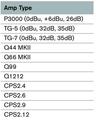
Table 5-15: Available amplifier types
OUTPUT LIMITERS

The Dx46's output channel limiters prevent audio signals from exceeding a set level. Press the Level button to change the output channel. Hold-down the Level button for some seconds - you will then be presented with the Limiter screen.
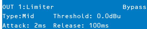
Use the < SELECT> buttons to navigate between Active/Bypass, Type, Threshold (-9.0 dBu to +21.0 dBu), Attack (0 ms to 50 ms) and Release (10.0 ms to 1000.0 ms). Adjust the values of each parameter using the up/ down VAL-UE arrows. The parameter Type allows selecting the used loudspeaker type. By selecting the type Sub, Lo, Mid or Hi the settings of the parameters Attack and Release are adjusted automatically. Select the type User for setting the parameters Attack and Release manually. The value of the parameter Threshold depends on the used speakers and the input sensitivity / gain of the used amplifiers.
TEMP Limiter
Additionally to the Peak-Limiter for the outputs there is a TEMP limiter available for each output. Parameters for the TEMP limiter are included in speaker settings files (.sps) and can be loaded to the device using the IRIS-Net control software.
6 Configurations of the Dx46
The Dx46 offers 7 pre-defined configurations. A configuration is a basic setting that includes the routing of inputs and outputs, the function of the outputs (Sub, Lo, Mid, Hi, Full Range) including basic X-Oover filter settings, and different channel/parameter linking schemes. The active configuration is defined by the selected preset i. e., each preset is based on a specific configuration which is also displayed next to the preset number and preset name. Each output employs two X-Over filters that can be assigned to a variety of filter types and slopes. Each output channel provides 5 additional filters which can be used as parametric EQs, Low-/ High-shelving filters, or Lo-Pass and Hi-Pass filters, and also as All-Pass filters. In addition to a gain control for adjusting the output level and a polarity switch, each output is monitored by a digital limiter with adjustable threshold, attack and release.
List and detailed description
- 2 Way Stereo + FR
3 Way Stereo
4 Way + FR - 5 Way + FR
Free Configuration - Full Edit 2 in 6 Out
3 Way Stereo - Mono Sub + FR
4 Way Stereo - Mono Sub/LF
CAUTION: Please use caution when changing configurations.
HINT: Not all parameters may be accessible in every preset and, depending on the configurations set by the contractor/installer, not all presets and/or preset values may be available for editing. Changes to preset availability, parameter availability and preset value ranges can only be set using the IRIS-Net application.
6.1 2 Way Stereo + Full Range
This configuration generally represents a 2-way stereo frequency crossover, where IN A serves as the left input channel and IN B as the right input channel. OUT 1 is the left Low-frequency output and OUT 2 is the left High-frequency output. OUT 4 and OUT 5 are the corresponding right Low-frequency and High-frequency output channels.
HINT: On Input channels, all Parametric EQ and Graphic EQ parameters are linked. For Output channels, linking applies to Crossovers, EQ, Delay Level and Limiter.
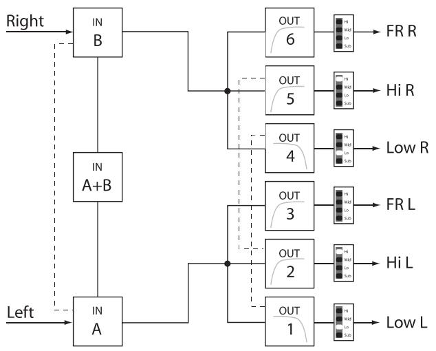
Linked Parameters
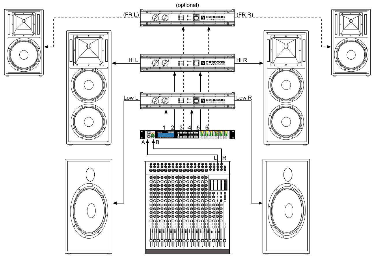
6.2 3 Way Stereo
This configuration represents a 3-way frequency crossover where IN A serves as the left input channel and IN B as the right input channel. OUTs 1 & 4 L/R are the Sub frequency channel, OUT 2 & 5 L/R are Low and Mid-frequency channels, 3 & 6 L/R are the Highfrequency channels.
HINT: On Input channels, all Parametric EQ and Graphic EQ parameters are linked. For Output channels, linking applies to Crossovers, EQ, Delay Level and Limiter.
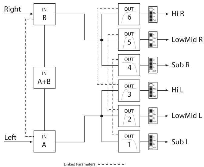
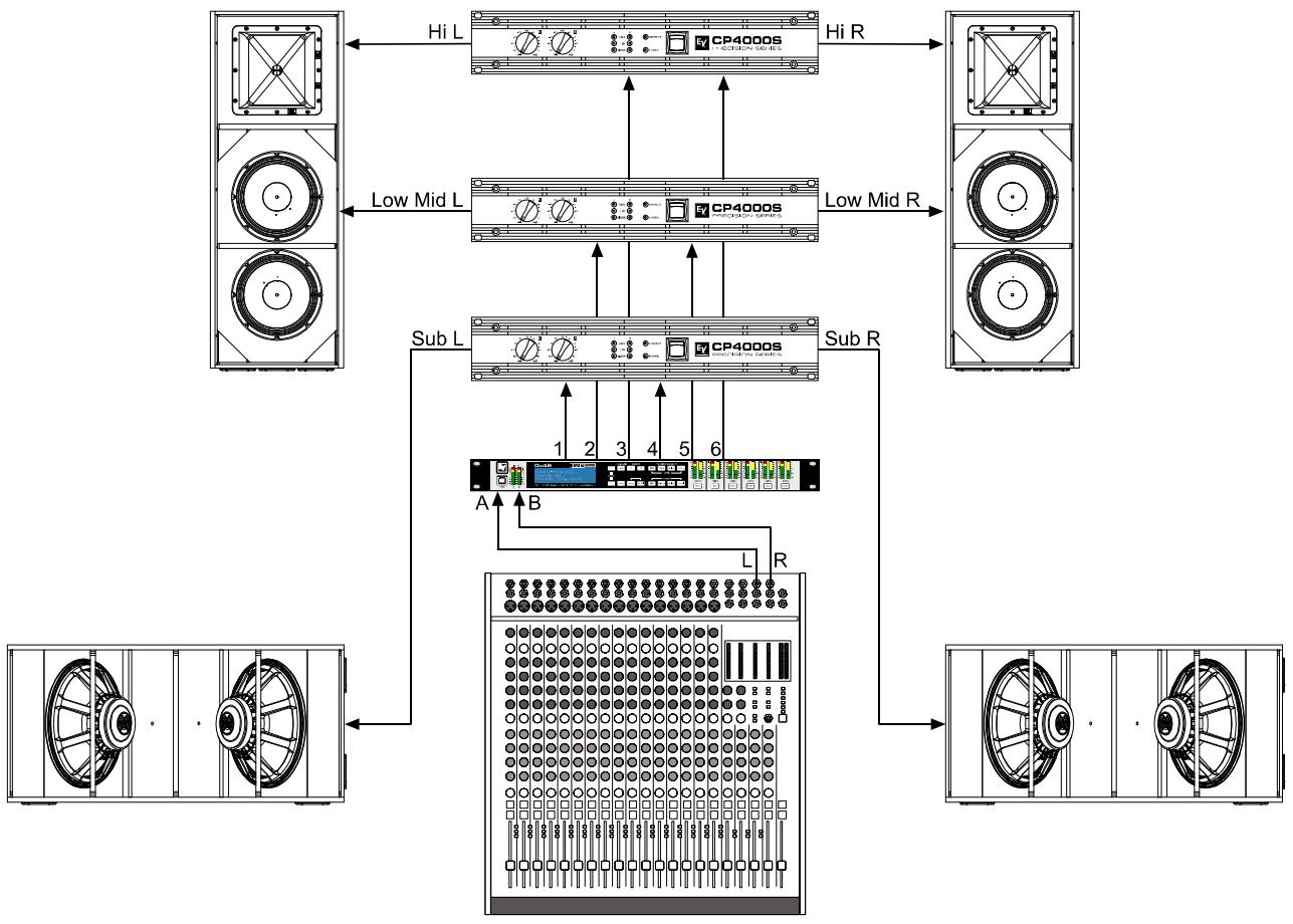
6.3 4 Way + FR
The 4 Way configuration is a monaural 4-way frequency x-over. Crossover channels are fed from IN A, full range channels are from IN B. OUT 1 is a mono Sub frequency channel, OUT 2 is a mono Low-frequency channel, OUT 3 is a mono Mid-frequency channel, and OUT 4 is the mono High-frequency. OUT 5 and OUT 6 are Fullrange channels.
HINT: On Input channels, all Parametric EQ and Graphic EQ parameters are not linked. For Output channels, linking applies to Crossover Highpass and Lowpass filters (see page 48 for details).
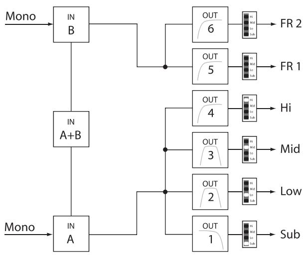
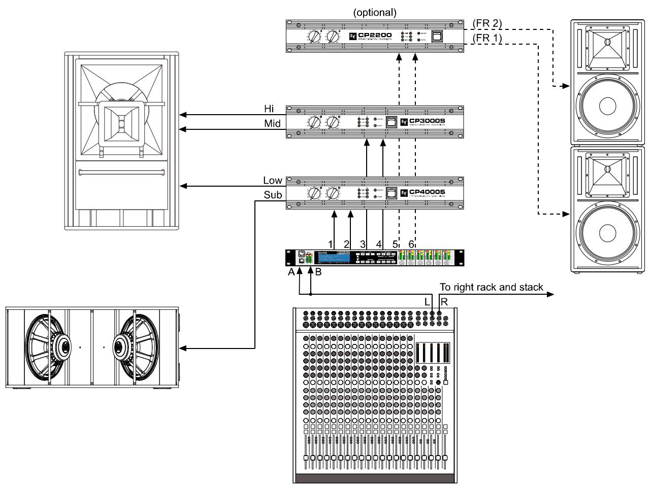
6.4 5 Way + FR
The 5-Way configuration is a monaural 5-way frequency x-over. Crossover channels are fed from IN A, full range channels are fed from IN B. OUT 1 is a mono Sub frequency channel, OUT 2 the mono Very Low-frequency, OUT 3 is the mono Low-frequency channel, OUT 4 is the mono Mid-Frequency channel, OUT 5 is the mono High-frequency channel and OUT 6 is the Full-range channel.
HINT: On Input channels, all Parametric EQ and Graphic EQ parameters are not linked. For Output channels, linking applies to Crossover Highpass and Lowpass filters (see page 48 for details).
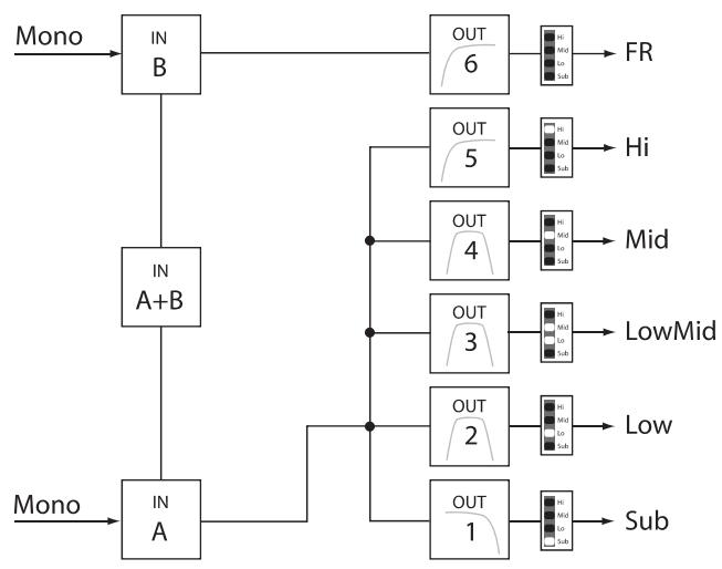
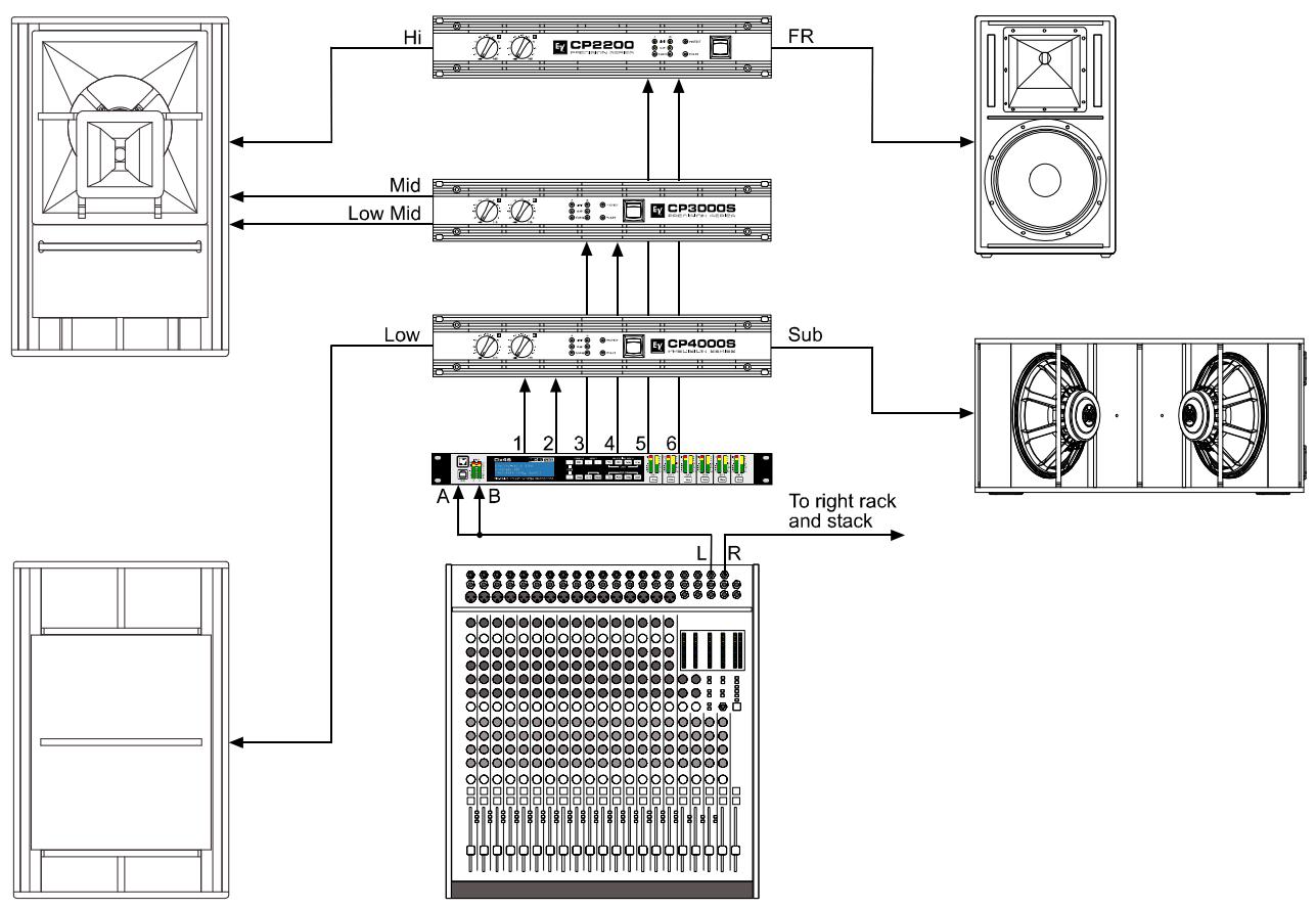
6.5 Free Configuration - Full Edit 2 In 6 Out
In this configuration, all 6 outputs are configured for full range operation. OUT 1, OUT 2 and OUT 3 get their signalfeed from IN A while OUT 4, OUT 5 and OUT 6 are fed from the input channel IN B. This configuration provides a "blank slate" for creating any custom routing and processing application.
HINT: In this Configuration, no channels or parameters are linked.
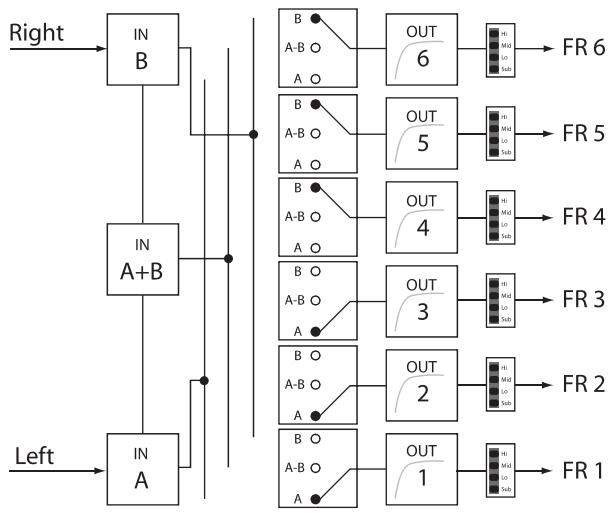
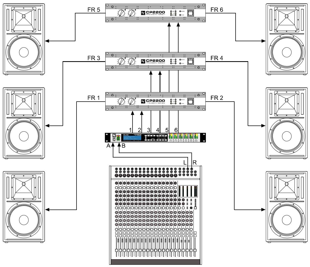
6.6 3 Way Stereo-MonoSub+FR
This 3-way configuration provides stereo crossover for Low-frequency and High-frequency devices and a summed mono feed for subs as well as a Full-range output. IN A serves at the left input and IN B serves as the right input. OUT 1 is a mono Sub-frequency channel, OUT 2 & 5 are L/R Low-frequency channels, OUT 3 & 6 are L/R High-frequency channels and OUT 4 is the Full-range channel.
HINT: On Input channels, all Parametric EQ and Graphic EQ parameters are linked. For Output channels, linking applies to Crossovers, EQ, Delay Level and Limiter.
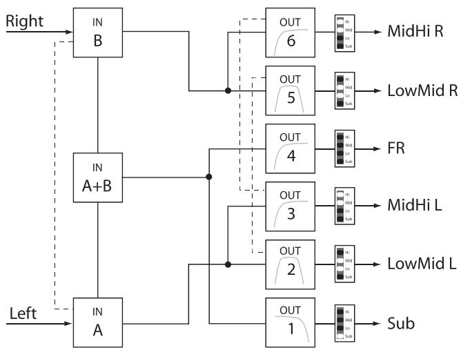
Linked Parameters
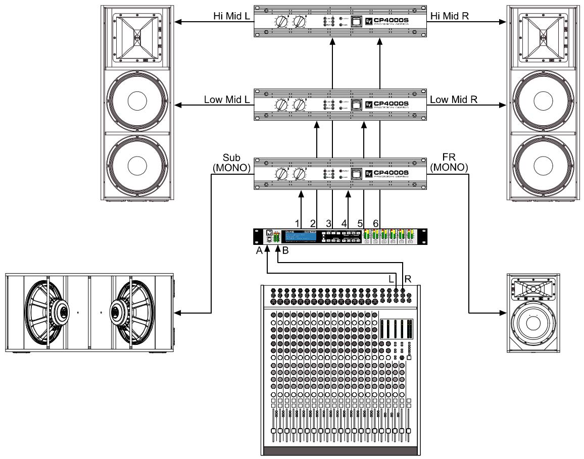
6.7 4 Way Stereo-MonoSub/LF
The 4 Way Stereo - MonoSub / LF configuration is a stereo 4 way frequency x-over. Mono Sub-frequency and Low-frequency channels are fed from IN A + IN B, Mid-frequency and High-Frequency left are fed from IN A, Mid-frequency and High-Frequency right are fed from IN B. OUT 1 is a mono Sub-frequency frequency channel, OUT 2 the mono Low-frequency channel, OUT 3 is the left Mid-frequency channel, OUT 4 is the left High-frequency channel, OUT 5 is the right Mid-frequency channel and OUT 6 is the right High-frequency channel.
HINT: On Input channels, all Parametric EQ and Graphic EQ parameters are linked. For Output channels, linking applies to Crossovers, EQ, Delay Level and Limiter.
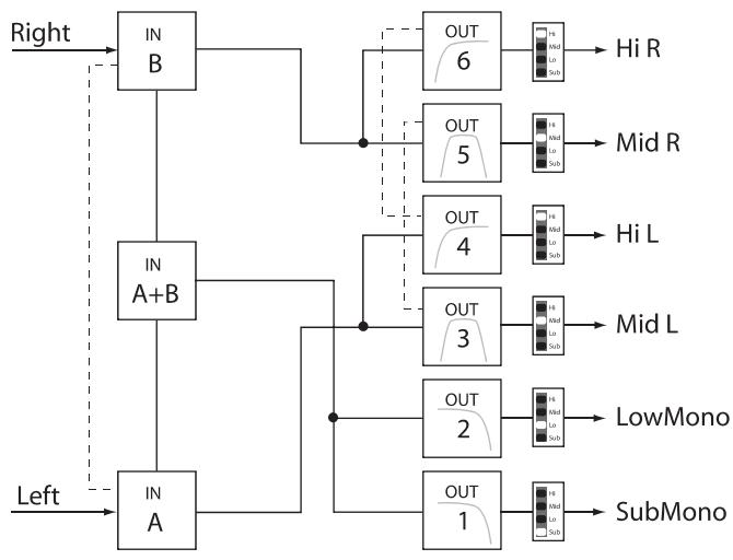
Linked Parameters
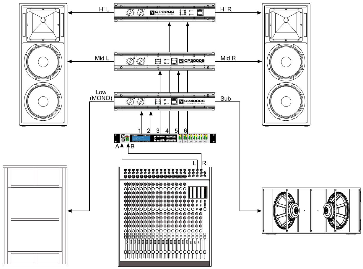
7 Operation Modes & Presets
Standard Configurations
This chart describes the channel assignments and linking schemes of the different configurations.
Chans and p t a d h i t. A dashed box around a Lo-pass/Hi-pass filter combination in adjacent channels indicates that these filters are linked. Changing the filter type and frequency of the Lo-pass filter will automatically change the linked Hi-pass filter on the adjacent channel and vice versa.
These links are only enforced while in Standard Edit Mode. When entering Full Edit Mode, all channel and parameter links are removed.
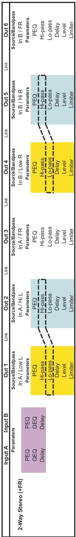

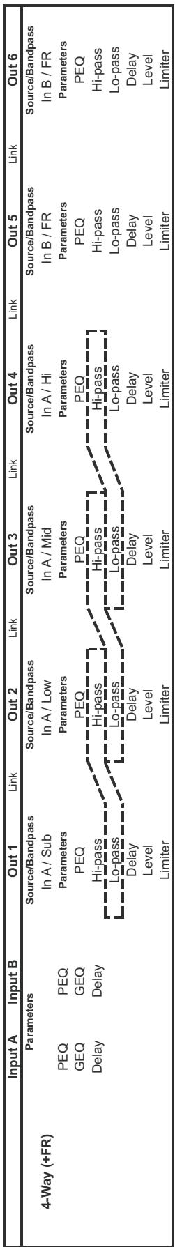
4
| Input A | Input B | Out 1 | Link | Out 2 | Link | Out 3 | Link | Out 4 | Link | Out 5 | Link | Out 6 | |
| 5-Way (+FR) | Parameters | Source/Bandpass | Source/Bandpass | Source/Bandpass | Source/Bandpass | Source/Bandpass | Source/Bandpass | ||||||
| In A / Sub | In A / Low | In A / Low-Mid | In A / Mid | In A / Hi | In B / FR | ||||||||
| PEQ | PEQ | Parameters | Parameters | Parameters | Parameters | Parameters | Parameters | ||||||
| GEQ | GEQ | PEQ | PEQ | PEQ | PEQ | PEQ | PEQ | ||||||
| Delay | Delay | Hi-pass | Hi-pass | Hi-pass | Hi-pass | Hi-pass | Hi-pass | ||||||
| Lo-pass | Lo-pass | Lo-pass | Lo-pass | Lo-pass | Lo-pass | ||||||||
| Delay | Delay | Delay | Delay | Delay | Delay | ||||||||
| Level | Level | Level | Level | Level | Level | ||||||||
| Limiter | Limiter | Limiter | Limiter | Limiter | Limiter | ||||||||
5
| Input A | Input B | Out 1 | Link | Out 2 | Link | Out 3 | Link | Out 4 | Link | Out 5 | Link | Out 6 | |
| Free Configuration | Parameters | Source/Bandpass | Source/Bandpass | Source/Bandpass | Source/Bandpass | Source/Bandpass | Source/Bandpass | ||||||
| In A / FR | In A / FR | In A / FR | In B / FR | In B / FR | In B / FR | ||||||||
| PEQ | PEQ | Parameters | Parameters | Parameters | Parameters | Parameters | Parameters | ||||||
| GEQ | GEQ | PEQ | PEQ | PEQ | PEQ | PEQ | PEQ | ||||||
| Delay | Delay | Hi-pass | Hi-pass | Hi-pass | Hi-pass | Hi-pass | Hi-pass | ||||||
| Lo-pass | Lo-pass | Lo-pass | Lo-pass | Lo-pass | Lo-pass | ||||||||
| Delay | Delay | Delay | Delay | Delay | Delay | ||||||||
| Level | Level | Level | Level | Level | Level | ||||||||
| Limiter | Limiter | Limiter | Limiter | Limiter | Limiter | ||||||||
6
| Input A | Input B | Out 1 | Link | Out 2 | Link | Out 3 | Link | Out 4 | Link | Out 5 | Link | Out 6 | |
| 3-Way Stereo, Mono Sub+FR | Parameters | Source/Bandpass In A+B / Sub Mono Parameters | Source/Bandpass In A / Low L Parameters | Source/Bandpass In A / Hi L Parameters | Source/Bandpass In A+B / FR Parameters | Source/Bandpass In B / Low R Parameters | Source/Bandpass In B / Hi R Parameters | ||||||
| PEQ | PEQ | PEQ | PEQ | PEQ | PEQ | PEQ | PEQ | ||||||
| GEQ | GEQ | Hi-pass | Hi-pass | Hi-pass | Hi-pass | Hi-pass | Hi-pass | ||||||
| Delay | Delay | Lo-pass | Lo-pass | Lo-pass | Lo-pass | Lo-pass | Lo-pass | ||||||
| Delay | Delay | Delay | Delay | Delay | Delay | ||||||||
| Level | Level | Level | Level | Level | Level | ||||||||
| Limiter | Limiter | Limiter | Limiter | Limiter | Limiter | ||||||||
7
| Input A | Input B | Out 1 | Link | Out 2 | Link | Out 3 | Link | Out 4 | Link | Out 5 | Link | Out 6 | |
| 4-Way Stereo, Mono Sub/LF | Parameters | Source/Bandpass In A+B / Sub Mono Parameters | Source/Bandpass In A+B / Low Mono Parameters | Source/Bandpass In A / Mid L Parameters | Source/Bandpass In A / Hi L Parameters | Source/Bandpass In B / Mid R Parameters | Source/Bandpass In B / Hi R Parameters | ||||||
| PEQ | PEQ | PEQ | PEQ | PEQ | PEQ | PEQ | PEQ | ||||||
| GEQ | GEQ | Hi-pass | Hi-pass | Hi-pass | Hi-pass | Hi-pass | Hi-pass | ||||||
| Delay | Delay | Lo-pass | Lo-pass | Lo-pass | Lo-pass | Lo-pass | Lo-pass | ||||||
| Delay | Delay | Delay | Delay | Delay | Delay | ||||||||
| Level | Level | Level | Level | Level | Level | ||||||||
| Limiter | Limiter | Limiter | Limiter | Limiter | Limiter | ||||||||
SAFETY COMPONENT (MUST BE REPLACED BY ORIGINAL PART)
OUT 1:Level/Limiter Level: 6.0dB Polarity:Inv Amp:User Gain:39dB
OUT 1:Level/Limiter Level:6.0dB Polarity:Inv Amp:TG-7 (O dBu)
OUT 1:Level/Limiter Level:6.0dB Polarity:Inv Amp:User Gain:39dB
OUT 1:Output Delay Active
Delay: 7.0
Unit: ms
IN A:GEQ Detail
F:20Hz Gain:0.0dB Active
Type: Symmetric Q Q: 4.3
3 Bedienelemente & Anschlüsse
30 - AES/EBU THRU-PORT
AUDIOKABEL (DIGITAL, AES/EBU)
Setup: NEW CONFIGURATIONCreate new empty configurationPress 'Store' to continue
Setup: DISPLAY Contrast: 0 Brightness: 1 Screensave: disable
Setup: LOCK Mode: Unlocked Code: 0000 Press 'Store' to Lock
EDITIER-MODUS WÄHLEN (EDITING)
Setup: EDITING Edit Mode: Full Link: Off
Setup: METERING
VU Mode: Peak hold
VU Reference: D/A Clip
Setup: LOCK Mode: Unlocked Code: 0000 Press 'Store' to Lock
Setup: DISPLAY Contrast: 0 Brightness: 1 Screensave: disable
5.2 Pegelanzeigen
EINGANGSSIGNALE
Normal fast
Peak Hold
Slow decay.
Press 'Recall' to load Any other key to cancel
Save Edits? Hit 'Store' Any other key to cancel
Setup: EDITING Edit Mode: Standard Link: Off
OUT 1:Routing Source: In B
OUT 1:Array Delay
Delay: 7.0
Unit: ms
Active
Crossover Alignment Delay
| Amp Type |
| Q44 |
| Q66 |
| CP1200 |
| CP1800 |
| CP2200 |
| CP3000S |
| CP4000S |
| P1200 (0dBu, +6dBu, 26dB) |
| P2000 (0dBu, +6dBu, 26dB) |
| P3000 (0dBu, +6dBu, 26dB) |
| TG-5 (0dBu, 32dB, 35dB) |
| TG-7 (0dBu, 32dB, 35dB) |
| Q44 MKII |
| Q66 MKII |
| Q99 |
| Q1212 |
| CPS2.4 |
| CPS2.6 |
| CPS2.9 |
| CPS2.12 |
LIMITER (AUSGANGSKANÄLE)

OUT 1:Limiter Bypass Type:Mid Threshold:0.0dBu Attack:2ms Release:100ms
7 Operation Modes & Presets
Konfigurationen
OUT 1:Level/Limiter Level:6.0dB Polarity:Inv Amp:User Gain:39dB
OUT 1:Level/Limiter Level:6.0dB Polarity:Inv Amp:TG-7 (O dBu)
OUT 1:Level/Limiter Level:6.0dB Polarity:Inv Amp:User Gain:39dB
OUT 1:Output Delay Active
Delay: 7.0
Unit: ms
IN A:GEQ Detail
F:20Hz Gain:0.0dB Active
Type: Symmetric Q Q: 4.3
6 - BOUTONS EDIT / COMPRE
Normal Fast,
Peak-Hold,
Slow Decay.
30 - PORT AES/EBU THRU
CABLE AUDIO (AES/EBU)
4 Setup (Configuration)
Setup: NEW CONFIGURATIONCreate new empty configurationPress 'Store' to continue
| Setup: DISPLAY |
| Contrast: 0 Brightness: 1 |
| Screensave: disable |
Setup: LOCK Mode: Unlocked Code: 0000 Press 'Store' to Lock
EDITING
Setup: METERING
VU Mode: Peak hold
VU Reference: D/A Clip
Setup: LOCK Mode: Unlocked Code: 0000 Press 'Store' to Lock
Verrouiller le Dx46
Setup: DISPLAY
Contrast: 0 Brightness: 1
Screensave: disable
5.2Vu-mètres
SIGNAUX D'ENTRÉE
Normal fast
Peak Hold
Slow decay.
Press 'Recall' to load Any other key to cancel
Save Edits? Hit 'Store' Any other key to cancel
Setup: EDITING Edit Mode: Standard Link: Off
Setup: EDITING Edit Mode: Full Link: Off
OUT 1:Routing Source: In B
OUT 1:Array Delay Active
Delay: 7.0
Unit: ms
OUT 1:Output Delay Active
Delay: 7.0
Unit: ms
OUT 1:Level/Limiter Level: 6.0dB Polarity:Inv Amp: H 5000 (O dBu)
| OUT 1:Limiter | Bypass | |
| Type:Mid | Threshold: 0.0dBu | |
| Attack: 2ms | Release: 100ms | |
This chart describes the channel assignments and linking schemes of the different configurations.
Chans and p t a d h i t. A dashed box around a Lo-pass/Hi-pass filter combination in adjacent channels indicates that these filters are linked. Changing the filter type and frequency of the Lo-pass filter will automatically change the linked Hi-pass filter on the adjacent channel and vice versa.
These links are only enforced while in Standard Edit Mode. When entering Full Edit Mode, all channel and parameter links are removed.

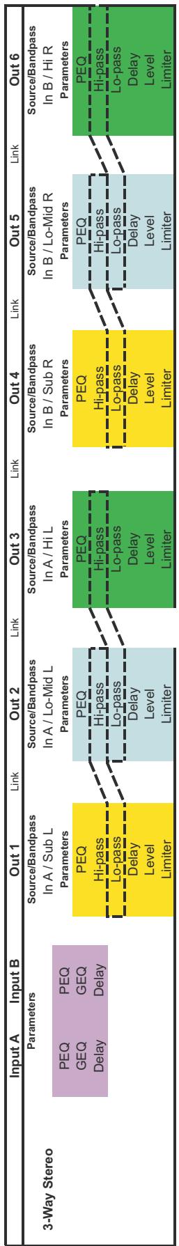

m
4
| Input A | Input B | Out 1 | Link | Out 2 | Link | Out 3 | Link | Out 4 | Link | Out 5 | Link | Out 6 | |
| 5-Way (+FR) | Parameters | Source/Bandpass | Source/Bandpass | Source/Bandpass | Source/Bandpass | Source/Bandpass | Source/Bandpass | ||||||
| In A / Sub | In A / Low | In A / Low-Mid | In A / Mid | In A / Hi | In B / FR | ||||||||
| PEQ | PEQ | Parameters | Parameters | Parameters | Parameters | Parameters | Parameters | ||||||
| GEQ | GEQ | PEQ | PEQ | PEQ | PEQ | PEQ | PEQ | ||||||
| Delay | Delay | Hi-pass | Hi-pass | Hi-pass | Hi-pass | Hi-pass | Hi-pass | ||||||
| Lo-pass | Lo-pass | Lo-pass | Lo-pass | Lo-pass | Lo-pass | ||||||||
| Delay | Delay | Delay | Delay | Delay | Delay | ||||||||
| Level | Level | Level | Level | Level | Level | ||||||||
| Limiter | Limiter | Limiter | Limiter | Limiter | Limiter | ||||||||
5
| Input A | Input B | Out 1 | Link | Out 2 | Link | Out 3 | Link | Out 4 | Link | Out 5 | Link | Out 6 | |
| Free Configuration | Parameters | Source/Bandpass | Source/Bandpass | Source/Bandpass | Source/Bandpass | Source/Bandpass | Source/Bandpass | ||||||
| In A / FR | In A / FR | In A / FR | In B / FR | In B / FR | In B / FR | ||||||||
| PEQ | PEQ | Parameters | Parameters | Parameters | Parameters | Parameters | Parameters | ||||||
| GEQ | GEQ | PEQ | PEQ | PEQ | PEQ | PEQ | PEQ | ||||||
| Delay | Delay | Hi-pass | Hi-pass | Hi-pass | Hi-pass | Hi-pass | Hi-pass | ||||||
| Lo-pass | Lo-pass | Lo-pass | Lo-pass | Lo-pass | Lo-pass | ||||||||
| Delay | Delay | Delay | Delay | Delay | Delay | ||||||||
| Level | Level | Level | Level | Level | Level | ||||||||
| Limiter | Limiter | Limiter | Limiter | Limiter | Limiter | ||||||||
6
| Input A | Input B | Out 1 | Link | Out 2 | Link | Out 3 | Link | Out 4 | Link | Out 5 | Link | Out 6 | |
| 3-Way Stereo, Mono Sub+FR | Parameters | Source/Bandpass In A+B / Sub Mono Parameters | Source/Bandpass In A / Low L Parameters | Source/Bandpass In A / Hi L Parameters | Source/Bandpass In A+B / FR Parameters | Source/Bandpass In B / Low R Parameters | Source/Bandpass In B / Hi R Parameters | ||||||
| PEQ | PEQ | PEQ | PEQ | PEQ | PEQ | PEQ | PEQ | ||||||
| GEQ | GEQ | Hi-pass | Hi-pass | Hi-pass | Hi-pass | Hi-pass | Hi-pass | ||||||
| Delay | Delay | Lo-pass | Lo-pass | Lo-pass | Lo-pass | Lo-pass | Lo-pass | ||||||
| Delay | Delay | Delay | Delay | Delay | Delay | ||||||||
| Level | Level | Level | Level | Level | Level | ||||||||
| Limiter | Limiter | Limiter | Limiter | Limiter | Limiter | ||||||||
7
| Input A | Input B | Out 1 | Link | Out 2 | Link | Out 3 | Link | Out 4 | Link | Out 5 | Link | Out 6 | |
| 4-Way Stereo, Mono Sub/LF | Parameters | Source/Bandpass In A+B / Sub Mono Parameters | Source/Bandpass In A+B / Low Mono Parameters | Source/Bandpass In A / Mid L Parameters | Source/Bandpass In A / Hi L Parameters | Source/Bandpass In B / Mid R Parameters | Source/Bandpass In B / Hi R Parameters | ||||||
| PEQ | PEQ | PEQ | PEQ | PEQ | PEQ | PEQ | PEQ | ||||||
| GEQ | GEQ | Hi-pass | Hi-pass | Hi-pass | Hi-pass | Hi-pass | Hi-pass | ||||||
| Delay | Delay | Lo-pass | Lo-pass | Lo-pass | Lo-pass | Lo-pass | Lo-pass | ||||||
| Delay | Delay | Delay | Delay | Delay | Delay | ||||||||
| Level | Level | Level | Level | Level | Level | ||||||||
| Limiter | Limiter | Limiter | Limiter | Limiter | Limiter | ||||||||
8 Specifications
| Property | Value |
| Mains Voltage | 100 to 240 V AC, 50 to 60 Hz |
| Power Consumption | 25 W |
| Analog Audio Inputs | 2 x XLR IN, electronically balanced 2 x XLR THRU OUT, electronically balanced |
| Digital Audio Inputs | 1 x XLR AES/EBU IN 1 x XLR AES/EBU THRU OUT |
| Digital Audio Format | AES3, 32 kHz to 192 kHz sample rate |
| Nominal Input Voltage | 1.55 V / +6 dBu |
| Maximum Input Voltage (with -6dB PAD engaged) | 17.3 V / +27 dBu |
| Input Impedance | 10 kΩ |
| Common Mode Rejection | -85 dB @ 1 kHz (typical) |
| A/D Conversion | 24-Bit Sigma-Delta |
| Analog Audio Outputs | 6 x XLR OUT, electronically balanced |
| Nominal Output Voltage | 1.55 V / +6 dBu |
| Maximum Output Voltage | 8.7 V / +21 dBu |
| Output Impedance | 50 Ω |
| D/A Conversion | 24-Bit Sigma-Delta |
| Frequency Response | 20 Hz to 22 kHz (+/-0.5 dB) |
| THD+N | < 0.002 % (band limited 22 Hz to 22 kHz) |
| Dynamic Range | 116 dB (A-weighted) |
| USB | USB Type B on front panel (PC Interface) |
| Ethernet | 2 x RJ-45 ports, 100 MB, Integrated Switch |
| Control Port | 1 x 6-pole Euro block Software Configurable for Preset Recall |
| Sample Rate | 48 kHz |
| Data Format | 24-Bit |
| Internal Processing | 48-Bit Double Precision |
| Signal Processing | Parametric EQs, 31 band Graphic EQs, Delays, Routing, X-Over, 512 Taps FIR filters, PA limiter, TEMP limiter, Level, Polarity, Signal generator |
| Operating Temperature Range | 0 °C to +40 °C |
| Dimensions (WxHxD) | 19 x 14.02 x 1.72 inches (483 x 356.1 x 43.6 mm) |
| Weight (Net) | 4.8 kg |
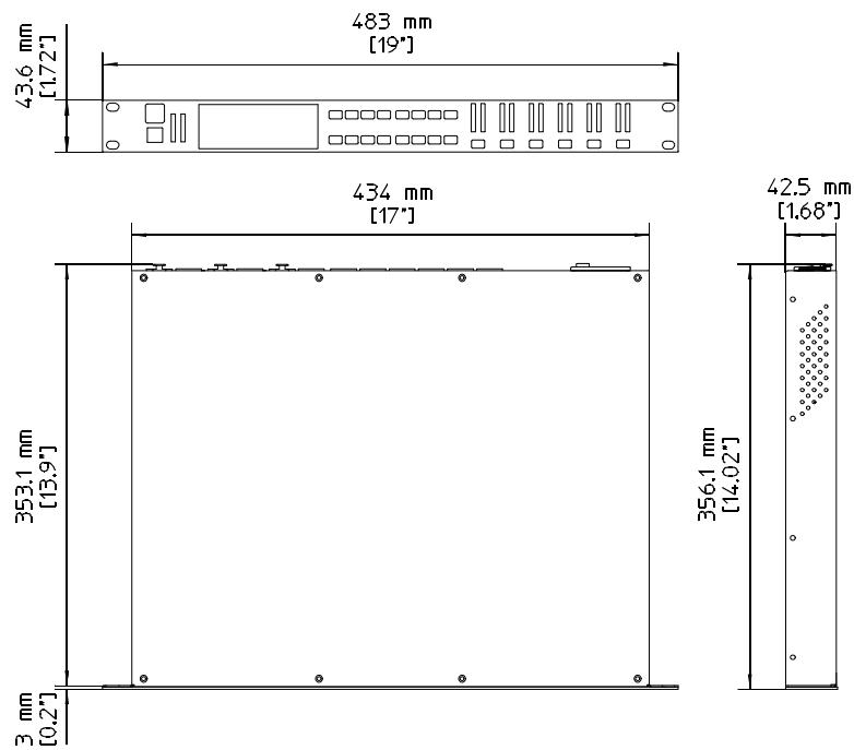
DIMENSIONS
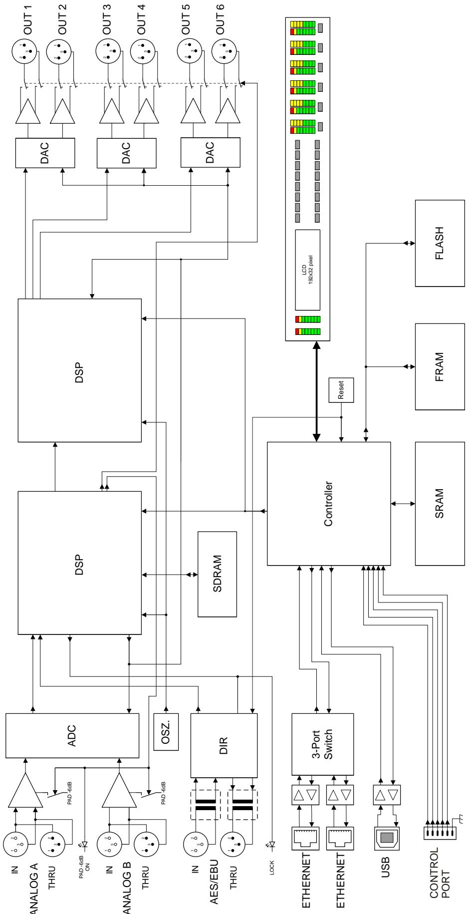
BLOCK DIAGRAM
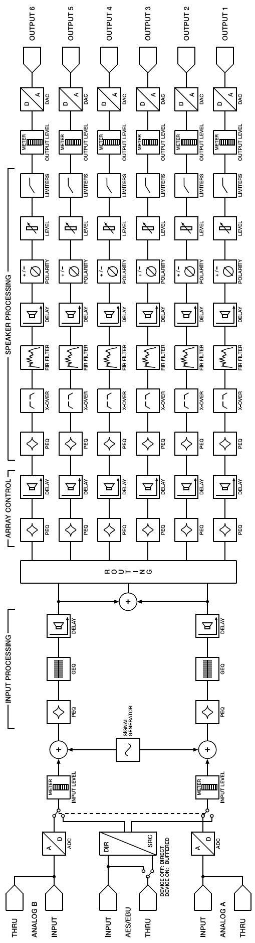
SIGNAL FLOW CHART
9 EQ Plot Images
9.1 6 dB PEQ Cuts Q Changes
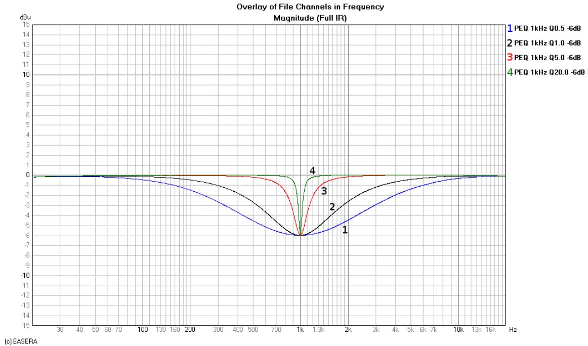
9.2 6 dB-Oct Shelves at 200 Hz and 2 kHz
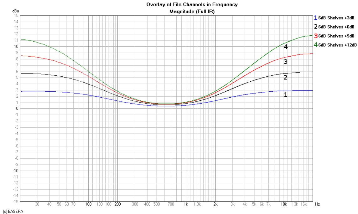
9.3 12 dB PEQ Cuts Q Changes
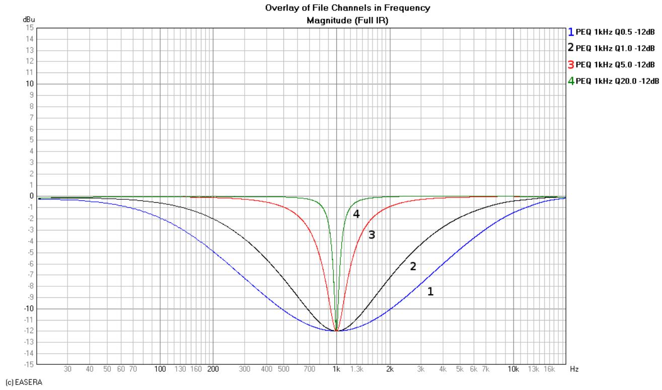
9.4 12dB-Oct Shelves at 200 Hz and 2 kHz
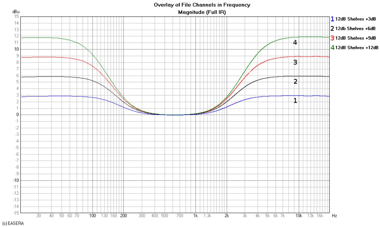
9.5 Bessel Filters
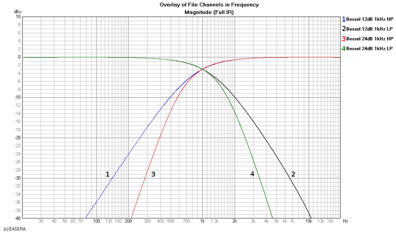
9.6 Butterworth Filters
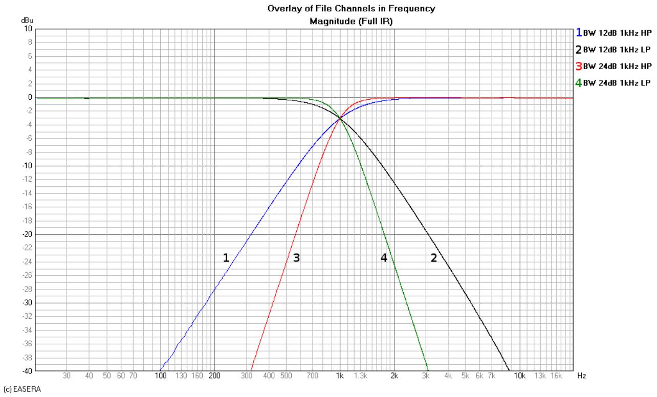
9.7 Hi Lo Pass Filters
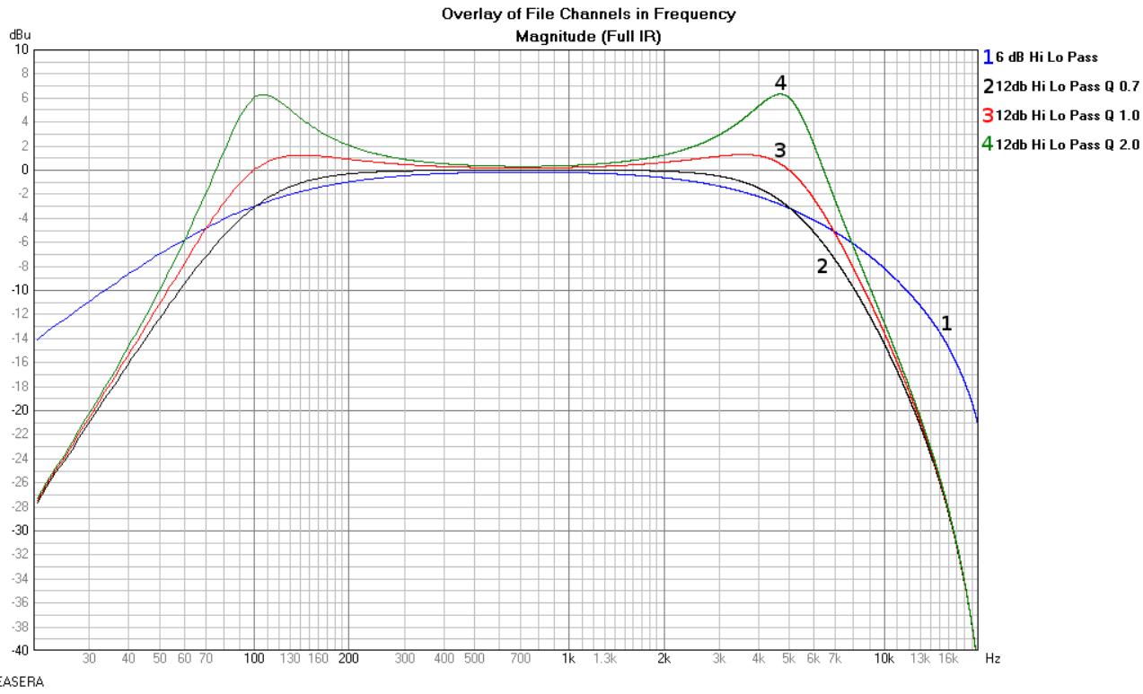
9.8 Linkwitz-Riley Filters
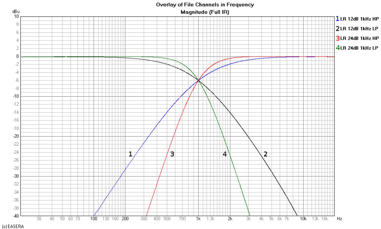
9.9 PEQ Gains
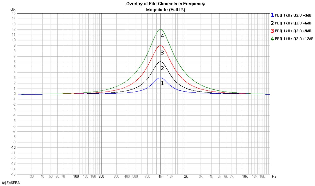
9.10 GEQ Curves