
VARIO 2000I - Generator SDMO - Free user manual and instructions
Find the device manual for free VARIO 2000I SDMO in PDF.



| Product type | Inverter generator |
| Brand | SDMO |
| Model | VARIO 2000I |
| Dimensions (L x W x H) | 53 x 28.5 x 45 cm |
| Weight (without fuel) | 20 kg |
| Fuel type | Unleaded gasoline (SP95-E10, SP95-E15, SP95-E85 prohibited) |
| Tank capacity | 2.8 L |
| Rated power | 1480 W |
| Maximum power | 1850 W |
| Output voltage (AC) | 230 V |
| Rated current (AC) | 6.4 A |
| 12 V output (DC) | 5 A |
| Engine type | OLYMP ES 100-1 |
| Recommended oil | SAE 15W40 |
| Oil capacity | 0.5 L |
| Sound pressure level (at 1 m) | 80 dB(A) |
| Oil safety | Yes (automatic shutdown in case of low oil) |
| Circuit breaker | Yes (overload and short circuit protection) |
| Electrical outlets | 2 x 10/16 A – 230 V (Schuko type) + 1 x 10 A – 12 V |
| Starting | Recoil starter (pull cord) |
| ECO/MAX mode | Selector to reduce consumption and noise (ECO) or provide more power (MAX) |
| Intended use | Domestic, occasional use |
| Warranty | 2 years or 150 hours of operation |
Frequently Asked Questions - VARIO 2000I SDMO
User questions about VARIO 2000I SDMO
0 question about this device. Answer the ones you know or ask your own.
Ask a new question about this device
Download the instructions for your Generator in PDF format for free! Find your manual VARIO 2000I - SDMO and take your electronic device back in hand. On this page are published all the documents necessary for the use of your device. VARIO 2000I by SDMO.
USER MANUAL VARIO 2000I SDMO
Instruction and maintenance manual
(Translation of the original note)
Manual de'utilisation y mantenimiento
(Versta is originalo)
Lietosanas un apkopes rokasgramata
29228 BREST Cedex 2 - France.
CS 92848 - 29228 BREST Cedex 2 - France.
| Contents | |
| 1. Preface | 5. Generating set maintenance |
| 2. Instructions and safety regulations (personal protection) | 6. Transporting and storing the generating set |
| 3. Getting started with the generating set | 7. Diagnostics for minor faults |
| 4. Using the generator set | 8. Technical specifications |
- Preface
| ! | Read this manual carefully before use. Keep it safe throughout the generating set's service life and always adhere to the safety advice and the usage and maintenance instructions contained in it. | |
| IMPORTANT |
The information contained in this manual is taken from technical data available at the time of print (the photos shown in this manual are not legally binding). In line with our policy of continually improving the quality of our products, this information may be amended without warning. On request, we can supply our original manuals in French via our website (www.sdmo.com).
In this manual, dangers are represented by the following two symbols:
| DANGER | Immediate danger. Indicates an imminent danger which may result in death or serious injury. Failure to follow the instruction shown may pose serious risks to the health and life of those concerned. |
| IMPORTANT | Potential danger. Indicates a dangerous situation if the warning is not heeded. Failure to follow the instruction indicated may cause minor injuries to those concerned or damage to equipment. |
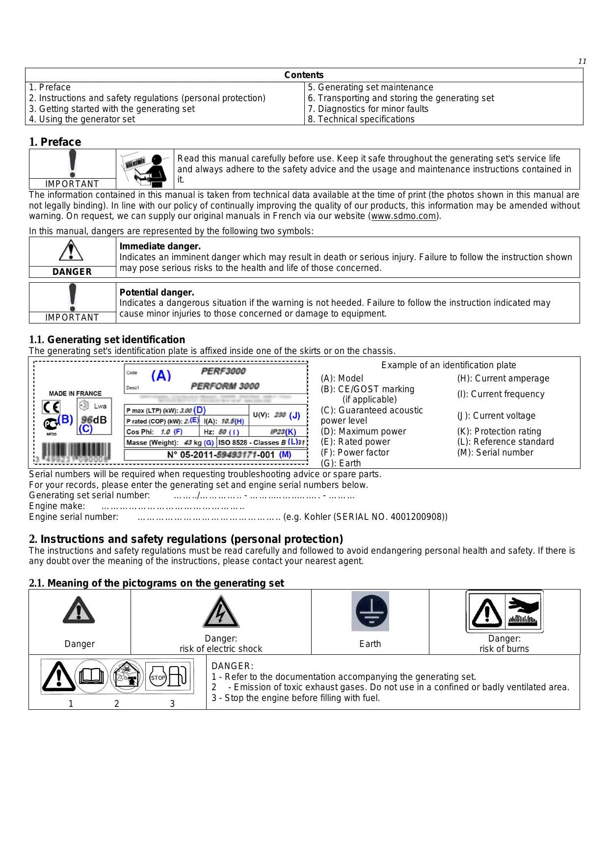
1.1. Generating set identification
The generating set's identification plate is affixed inside one of the skirts or on the chassis.
| MADE IN FRANCE | Code (A) | PERF3000 | Example of an identification plate | ||
| Desc1 | PERFORM 3000 | (A): Model | (H): Current amperage | ||
| (B): CE/GOST marking | (I): Current frequency | ||||
| (if applicable) | |||||
| P max (LTP) (kW): 3.00 (D) | U(V): 230 (J) | (C): Guaranteed acoustic power level | (J): Current voltage | ||
| P rated (COP) (kW): 2.5 (E) | I(A): 10.5(H) | ||||
| Cos Phi: 1.0 (F) | Hz: 50 (I) | IP23(K) | (D): Maximum power | (K): Protection rating | |
| Masse (Weight): 43 kg (G) | ISO 8528 - Classes B (L)31 | (E): Rated power | (L): Reference standard | ||
| N° 05-2011-59493171-001 (M) | (F): Power factor | (M): Serial number | |||
| (G): Earth | |||||
Serial numbers will be required when requesting troubleshooting advice or spare parts.
For your records, please enter the generating set and engine serial numbers below.
Generating set serial number:
Engine make:
Engine serial number: (e.g. Kohler (SERIAL NO. 4001200908))
2. Instructions and safety regulations (personal protection)
The instructions and safety regulations must be read carefully and followed to avoid endangering personal health and safety. If there is any doubt over the meaning of the instructions, please contact your nearest agent.
2.1. Meaning of the pictograms on the generating set
| Danger | Danger: risk of electric shock | Earth | Danger: risk of burns |
| 1 | 2 | 3 | DANGER: 1 - Refer to the documentation accompanying the generating set. 2 - Emission of toxic exhaust gases. Do not use in a confined or badly ventilated area. 3 - Stop the engine before filling with fuel. |
2.2. General guidelines
Generating sets in the general public (non-professional) range are reserved solely for domestic use; they should not be used for professional work.
Never let other people use the generating set without having given them all the necessary instructions beforehand. Never allow a child to touch the generating set, even when switched off, and do not operate the generating set when animals are in the vicinity (fear, disturbance, etc.).
In all cases, respect the local regulations currently in place concerning the use of generating sets.
2.3. Risk of electrocution
| DANGER | RISK OF ELECTROCUTION Generating sets supply electrical current while operating; comply with the applicable legislation as well as the installation and usage recommendations given in this manual. Do not connect the generating set directly to other power source (e.g. mains); install a source inverter. | |
For all connections, use flexible, strong rubber-sheathed cable which complies with standard IEC 60245-4 or equivalent cables, and ensure that they are kept in perfect condition. Adhere to the cable lengths indicated in the table in the paragraph entitled "Cable sizes". Connect class I equipment to the generating set using a cable equipped with a PE protective conductor (green/yellow); this protective conductor is not required for class II equipment. Only use one class I electrical device per socket. Depending on the conditions of use (A, B or C), also apply the following protective measures:
A - If the generating set is not equipped with an integrated differential protection device at delivery (standard version with insulated neutral on the generating set's earth terminal):
- Use a differential device calibrated to 30mA at the output of each of the generating set's socket (place each device at least 1m from the generating set, protecting it from weather conditions).
- If one or more mobile or portable devices are used occasionally, the generating set does not need to be earthed.
B - If the generating set is equipped with an integrated differential protection device at delivery (standard version with alternating neutral connected to the generating set's earth terminal - for use with TT or TN systems):
- When supplying a temporary or semi-permanent installation (work site, show, fairground, etc.), earth the generating set*.
- When supplying a fixed installation (e.g. as backup for mains outages), the generating set must be connected by a qualified electrician in accordance with the regulations applicable at the installation site.
C- Mobile applications (e.g. generating set installed on a moving vehicle)
The generating sets are intended to operate while stationary. They may not be installed on a vehicle or other mobile equipment unless a study has been carried out analysing the various installation and usage specifications. It is prohibited to use the generating set whilst it is in motion. If earthing is not possible, connect the generating set's earth terminal to the vehicle earth.
Never touch stripped cables or disconnected connectors. Never handle a generating set with wet hands or feet. Never expose the equipment to liquid splashes or rainfall, and do not place it on wet ground.
If you are in any doubt regarding installation, please contact your nearest agent.
- To earth the generating set: fit a 10 ~mm^2 copper wire to the generating set's earth terminal and to a galvanised steel earthing rod set 1 metre into the ground
2.3.1 Selecting the connection cables (cable cross section)
Adhere to the cross sections and lengths recommended in this table during installation or when using electrical extensions.
| Generating set type: | Single phase | Three-phase | |||||||||
| Generating set socket type: | 10 A | 16 A | 32 A | 10 A | 16 A | ||||||
| Recommended cable cross section | mm² | AWG | mm² | AWG | mm² | AWG | mm² | AWG | mm² | AWG | |
| Length of cable used | 0 to 50 m | 4 | 10 | 6 | 9 | 10 | 7 | 1.5 | 14 | 2.5 | 12 |
| 51 to 100 m | 10 | 7 | 10 | 7 | 25 | 3 | 2.5 | 12 | 4 | 10 | |
| 101 to 150 m* | 10 | 7 | 16 | 5 | 35 | 2 | 4 | 10 | 6 | 9 | |
*This cable length is the maximum permitted length, and must not be exceeded.
Installation method = cables on raceway or non-drilled tablet/Permitted drop in voltage = 5%/Multi-core conductors/Cable type PVC 70^ (e.g. H07RNF)/Ambient temperature =30°C.
2.4. Risks relating to exhaust gases
| DANGER | RISK OF POISONING The carbon monoxide present in the exhaust gas may lead to death by inhalation if the concentration levels in the atmosphere are too high. Always use the generating set in a well ventilated area where the gases cannot accumulate. |
For safety reasons and for correct operation of the generating set, correct ventilation is essential (risk of intoxication, engine overheating and accidents involving, or damage to, the surrounding equipment and property). If it is necessary to operate it inside a building, the exhaust gases must be evacuated outside and adequate ventilation must be provided so that any people or animals present are not affected.
2.5. Risk of fire
| DANGER | RISK OF FIRE Never operate the generating set in areas containing flammable products (risk of sparks). Keep all inflammable or explosive materials (petrol, oil, fabric, etc.) out of the way. when the generating set is operating. Never cover the generating set with any type of material while it is in operation or just after it has been switched off: always wait until the engine cools down (at least 30 minutes). | |
2.6. Risk of burns
| ! | Never touch the engine or the silencer while the generating set is in operation, or when it has just stopped. Wait for the engine to cool before carrying out any work (at least 30 minutes). |
| IMPORTANT |
Hot oil burns; avoid contact with the skin. Before carrying out any operation, check that the system is no longer pressurised. Never start or run the engine if the oil filler cap is off (oil may splash out).
2.7. Guidelines for protecting the environment
Drain the engine oil into a designated container: never drain or discard engine oil onto the ground.
As far as possible, avoid sound reverberating through walls or buildings (the noise will be amplified).
If the generating set is used in wooded, bushy or uncultivated areas and if the exhaust silencer is not fitted with a spark arrester, clear any vegetation away from the area and take care that the sparks do not cause a fire. Once the generating set is no longer being used (end of product life), take it to a waste collection point.
3. Getting started with the generating set
3.1. Key to illustrations
The cover illustrations can be used to identify the various components of the generating set. The procedures in the manual refer to these illustrations using letters and numbers as identifiers, for example, "A-1" refers to the number 1 on figure A.
| A | 1 | Earth connection | 10 | Tank pressurisation pump |
| 2 | Inspection cover | 11 | Indicator lamps A. Operating light B. Overload indicator C. Oil safety indicator | |
| 3 | Fuel tap | |||
| 4 | Fuel tank aeration pointer | |||
| 5 | Fuel tank cap | |||
| 6 | Choke | 12 | 12V socket (if fitted) | |
| 7 | Recoil starter | 13 | Spark plug access cover | |
| 8 | Electrical socket | 14 | Muffler | |
| 9 | MAX / ECO Mode |
| B | 1 | Inspection trap cover |
| 2 | Oil filler and drain plug Maximum oil filling level |
| C | 1 | Fuel tank aeration pointer ON/OFF |
| 2 | Tank pressurisation pump | |
| 3 | Fuel strainer Maximum fuel filling level | |
| 4 | Fuel filter |
| D | 1 | Air filter cover |
| 2 | Filter element Filter element cleaning |
| E | 1 | Spark plug access cover |
| 2 | Spark plug |
3.2. Initial commissioning
On taking delivery of the generating set, check that it is complete and not damaged in any way. If the generating set is equipped with a transport bracket located on the engine, remove it. Top up the oil (if necessary) and fuel, and connect the battery (if fitted). Never invert the positive and negative terminals on the battery (if fitted) when connecting it, as this could cause serious damage to the electrical equipment. Some generating sets require a running in period. Contact your nearest agent for more information.
- Using the generator set
| ! | Before using, it is necessary to understand all of the controls and manoeuvres. To stop the generating set in an emergency, close the fuel tap. This generating set is designed for occasional domestic use. |
| IMPORTANT |
4.1. Positioning the generating set for operation
| ! | The generating sets are intended to operate while stationary. They may not be installed on a vehicle or other mobile equipment unless a study has been carried out analysing the various installation and usage specifications. It is prohibited to use the generating set whilst it is in motion. |
| IMPORTANT |
Choose a site that is clean, well ventilated and sheltered from bad weather.
Place the generating set on a flat, horizontal surface which is firm enough to prevent the generating set sinking down (under no circumstances should the set tilt in any direction by more than 10^ ).
The stocks of additional oil and fuel must not be located near to the generating set when it is in operation or still hot.
4.2. Check the generating set is in a good general condition (bolts, hoses)
Inspect the entire generating set before start-up and after each use to prevent any faults or damage.
1 Check all the pipes and hoses to ensure they are in good condition and that there are no leaks.
Pipes or hoses must be replaced by a specialist technician. Please contact your nearest agent.
2 Tighten any loose nuts or bolts.
The cylinder head bolts must be retightened by a specialist technician. Please contact your nearest agent.
4.3. Checking the engine oil level and topping up
| IMPORTANT | Before starting the generating set, always check the engine oil level. Top up with the recommended oil (see § Specifications) using a funnel, up to the upper limit of the gauge. |
1 Open the inspection cover (fig. A - no. 2).
Unscrew the oil filler plug (fig. B - no. 2).
3 Check the oil level: generating set on a level surface, the oil should reach the filler neck.
If necessary top up using the funnel.
Screw the filler plug back on.
Wipe off excess oil with a clean cloth.
7 Close the inspection cover.
4.4. Checking the fuel level and topping up
| DANGER | Fill with fuel with the engine off and in accordance with the safety instructions and the legislation in force. Before opening the fuel tank cap, always place the vent tab in the ON position. | |
1 Close the fuel tap (A-3).
Place the fuel tank's vent tab in the ON position (A-4 & C-1).
3 Undo the fuel tank cap (A-5).
4 Visually check the fuel level (C-3). If necessary, fill with fuel:
5 Fill the fuel tank up to the maximum level using a funnel, taking care not to spill any fuel.
| ! | Use only clean fuel without any water. (SP95-E10; SP95-E15; SP-95-E85 prohibited). Do not overfill the tank (there should not be any fuel in the filler neck). After filling, always ensure that the tank's filler cap is properly tightened. If any fuel has been spilt, make sure that it has dried and that any vapours have cleared before starting up the generating set. |
| IMPORTANT |
Screw the cap back onto the fuel tank.
7 Place the fuel tank's vent tab in the "OFF" position.
4.5. Starting the generating set
To restart the generating set after a stoppage of more than 10 min or when the fuel level has dropped to half the tank or lower, pressurise the fuel tank with the pressurisation pump.
1 Set the fuel tank aeration pointer to (A-4 & C-1).
2 Open the fuel tap (A-3).
3 Set the choke lever (A-6) to "V".
4 Slowly pull the recoil starter (A-7) once until it engages, then allow it to gently return.
Then give a quick and firm pull on the recoil starter until the engine starts. When starting the generating set for the first time or after a long storage period, it may be necessary to pull the recoil starter ten times.
Slowly set the choke to "||" and let the generating set run a few minutes before use.
4.5.1 Use the tank's pressurising pump
The fuel tank must be pressurised with a pump:
- after a shut down of the generating set for over 10 minutes,
- when the fuel level has dropped to half of the tank and below.
The tank pressurisation pump must not be activated more than ten times.
| ! | Never use the fuel tank pressurisation pump when the fuel level is above half of the tank level or when the generating set is in operation (risk of damaging the generating set). |
| IMPORTANT |
1 Set the fuel tank aeration pointer to OFF (C-1).
2 Activate the tank pressurisation pump (C-2) 10 times maximum.
Start the generating set by sliding the fuel tank aeration pointer to OFF.
As soon as the generating set has started, set the tank aeration pointer to ON.
Slowly set the choke to "||" and let the generating set run a few minutes before use.
4.6. Using the electricity supplied
1 Check that the operating light is turned on (A-11, A).
2 Activate the "MAX" or "ECO" mode (A-9).
3 Connect the devices to the generating set sockets (A-8).
In case of overload or short-circuit, the operating light (A-11, A) switches-off and the overload indicator (A-11, B) glows: Stop the generating set and eliminate the overload.
4.6.1 Use the MAX-ECO mode
This generating set has a variable engine rating by which operation can be adjusted according to requirements. This is the MAX-ECO mode (A-9). MAX - I : When the button is in the "MAX" position, the generating set can react to large inrush current.
ECO - O : The "ECO" position is useful for smaller loads. The generating set consumes less and is quieter.
4.6.2 Use the 12V socket
| DANGER | RISK OF POISONING OR EXPLOSION Follow the battery manufacturer's recommendations. Use only insulated tools. Never use sulphuric acid or acid water to top up the electrolyte level. Never leave the battery close to a flame or fire. Always ensure adequate ventilation during charging. |
Certain generating set models are equipped with a 12V socket (A-12) which can only be used for devices operating at 12 V, always with the use of a buffer battery (car battery). This socket can also be used for occasional brief battery charging operations.
| The generating set does not have a charge controller, therefore the charge is not regulated or limited. Always observe the charging time, regularly checking the battery using a hydrometer (acid). Never leave the battery unattended during charging. Always disconnect the generating set's battery when charging is complete (permanent charge, risk of damage). Do not leave the battery connected to the vehicle and never attempt to start the vehicle while the battery is being charged. Observe the polarities and connect the cables before starting the generating set. | |
| IMPORTANT | |
1 If the generating set is operating, switch it off (see § Switching the generating set off).
2 Connect the 12 V cables to the generating set's 12 V socket and to the battery terminals (red: +; black: -).
3 Start the generating set. If the circuit breaker trips, switch off the generating set and disconnect the battery.
Set the generating set to MAX mode (A-9).
Monitor the charge and check the battery regularly. The use of other sockets on the generating set is then possible.
6 Once charging is complete, switch off the generating set before disconnecting the 12V cables.
4.7. Switching the generating set off
Switch off and disconnect the devices.
2 Allow the engine to run for 1 or 2 minutes.
3 Close the fuel tap (A-3) and place the fuel tank's vent tab in the "OFF" position (A-3). The generating set is turned off.
| ! | Always ensure that the generating set is suitably ventilated. Even when the unit is turned off, the engine continues to give off heat. |
| IMPORTANT |
5. Generating set maintenance
The maintenance operations to be carried out are detailed in the maintenance table. The interval for this is supplied as a guide and for generating sets operating with fuel and oil which conform to the specifications given in this manual. Shorten the maintenance intervals according to the conditions in which the generating set is used, and as required (for example, clean the air filter more frequently if the generating set is used in dusty environments).
5.1. Reminder of use
As a safety measure, maintenance should be performed on the generating set regularly and carefully by people who have the necessary experience and are equipped with suitable tools. Any warranty becomes void in the event of failure to respect the maintenance recommendations. For any questions about a special operation, please contact your nearest agent who will advise and help you.
5.2. Maintenance intervals table
| Operation to be carried out at whichever deadline is reached first: | Each time it is used | Every month/10 hours | Every 6 months/100 hours | Every year/300 hours | |
| Generating set | Check the general condition | X | |||
| Clean the generating set | X | ||||
| Check/Clean the spark plug | X | ||||
| Oil | Check the level | X | |||
| Change | X | X | |||
| Fuel | Check the level | X | |||
| Cleaning the screen filter | X | ||||
| Replace the filter (if fitted) | X | ||||
| Clean the pipes and tank* | X* | ||||
| Air filter | Clean/replace the filter | X | |||
| Valves | Adjust the play* | X* | |||
- Operations must only be carried out by one of our agents.
5.3. Performing the maintenance operations
| ! | Before carrying out any maintenance operation: - switch off the generating set - disconnect the spark plug cap. |
| IMPORTANT |
Only use original parts or equivalent parts to prevent damage to the generating set. To perform proper maintenance operations, it is necessary to open the access cover or undo the inspection flap on the generating set; close or retighten them as soon as these operations have been performed.
5.3.1 Top up the oil
The used oil and filter must be recycled or eliminated according to the local regulations in force. In order for the drain operation to be more effective, it is advisable to run the generating set for around ten minutes before the drain operation in order to make the oil more fluid.
1 With the engine warm, remove the drain/filler cap (B-2).
Tilt the generating set slightly to drain the oil into a suitable container. Do not tilt the generating set completely onto its side.
3 Once drainage is complete, fill up with the recommended oil (see § Specifications), and check the level. Too much or too little oil can damage the generating set engine.
4 Refit the drain/filler cap.
Check that there are no oil leaks.
Wipe off any traces of oil with a clean cloth.
5.3.2 Cleaning the screen filter
| DANGER | RISK OF EXPLOSION Respect the local regulations in force concerning the handling of petroleum products. Do not smoke, cause sparks or bring naked flames into the vicinity. Ensure that the vapours have dispersed before starting the generating set. | |
Fuel will run out during this operation; use a suitable container.
1 Close the fuel tap (A-3).
2 Remove the fuel tank cap (A-5) and the fuel screen filter (C-3).
Use a low-pressure compressed air gun to blow air on the screen filter from the outside inwards.
4 Rinse with clean fuel.
5 Refit the screen filter and carefully screw the fuel tank cap back in.
5.3.3 Replace the fuel filter
| DANGER | RISK OF EXPLOSION Respect the local regulations in force concerning the handling of petroleum products. Do not smoke, cause sparks or bring naked flames into the vicinity. Ensure that the vapours have dispersed before starting the generating set. |
Fuel will run out during this operation; use a suitable container.
1 Close the fuel tap (A-3).
Note the fitting direction of the filter and remove the fuel filter by releasing the hose clamps (C-1/4).
Fit the new fuel filter in the correct fitting direction and reconnect the hoses, securing them with the clamps.
Wipe away any traces of fuel with a clean cloth and check that there are no leaks.
5.3.4 Clean or replace the air filter
| ! | Never use petrol or flammable solvents for cleaning the air filter element (risk of fire or explosion). |
| IMPORTANT |
1 Remove the filter cover (D-1).
Remove the filter element (D-2) and check the type of clogging:
Dry clogging:
Use a low-pressure dry compressed air gun to blow from the inside of the filter element out, moving from the top to the bottom until there is no more dust.
4 Check the condition of the filter element: replace it if it is at all damaged.
5 Refit the filter element and its cover.
Moist/oily clogging:
Replace the filter element.
4 Refit the filter element and its cover.
5.3.5 Clean or replace the spark plug
1 Open the spark plug access cover (E-1) and fit the spark plug with the help of a plug spanner (supplied).
Check the condition of the spark plug:
If the electrodes are worn out or if the insulator is cracked or chipped:
3 Replace the spark plug.
Fit the new spark plug and hand screw it so as not to cross-thread
5 With a plug spanner, tighten 1/2turn after the plug seating to compress the washer.
Or else:
3 Clean the plug with a metallic brush.
4 With a shim, check the gap of the electrodes: It should be between 0.7 to 0.8mm
Check condition of the washer.
Fit the spark plug and hand screw it so as not to cross-thread.
With a plug spanner, tighten 1/8 - 1/4 turn after the plug seating to compress the washer.
5.3.6 Cleaning the generating set
| ! | Never wash the generating set with a water jet or high pressure cleaner. |
| IMPORTANT |
1 Remove all dust and debris from around the exhaust silencer (A-14).
Wash the outside of the generating set using a sponge and water with a mild detergent added (e.g. car shampoo). A cleaning foam may be used and wiped off using a soft, absorbent cloth.
③ Rinse using the sponge with fresh water to remove any trace of cleaning product.
6. Transporting and storing the generating set
6.1. Transport and handling conditions
Before transporting the generating set, check that the bolts are correctly tightened, close the fuel tap (if fitted) and disconnect the battery (if fitted). The generating set should be transported in its normal operating position; never lay it on its side. A pump unit should be handled gently and brusque movements should be avoided. Ensure that the place where it is to be stored or used is carefully prepared beforehand.
6.2. Storage conditions
This procedure for storing the generating set or protecting it over the winter must be respected if the generating set is not used for a period of between 2 months and 1 year. For longer periods of storage, it is recommended to contact your nearest agent or to start up the generating set for a few hours every year, and respect the storage procedure after doing so.
This operation requires the addition of a preservative to the fuel tank or complete drainage of the fuel tank (use a suitable container).
1 Open the inspection flap.
2 With a suitable container in place and without closing the fuel tap, open the fuel tank cap and remove the fuel filter.
3 Allow the fuel to completely drain into the container (drainage of the tank and pipes) then fit a new fuel filter.
Close the fuel tank cap, place the vent tab in the "ON" position and use the starter (position ) to start the generating set. Allow the generating set to operate until it runs out of fuel.
4 Close the fuel tap and the vent tab ("OFF"), wipe off any trace of fuel and check for leaks.
Top up the oil while the engine is warm.
6 Open the access cover for the spark plug, remove it (E-2) and pour approximately 3 ml (1 tablespoon) of clean engine oil into the cylinder via the spark plug orifice; then refit the spark plug and close the access cover.
Pull the starter-recoil reel handle (A-7) 3 or 4 times to distribute the oil in the cylinders and protect them from corrosion.
Clean or replace the air filter (depending on the condition) and close the inspection flap.
9 Clean the generating set and cover it with a protective cover to protect it from dust.
Store the generating set in a clean, dry place. Do not store it on its side.
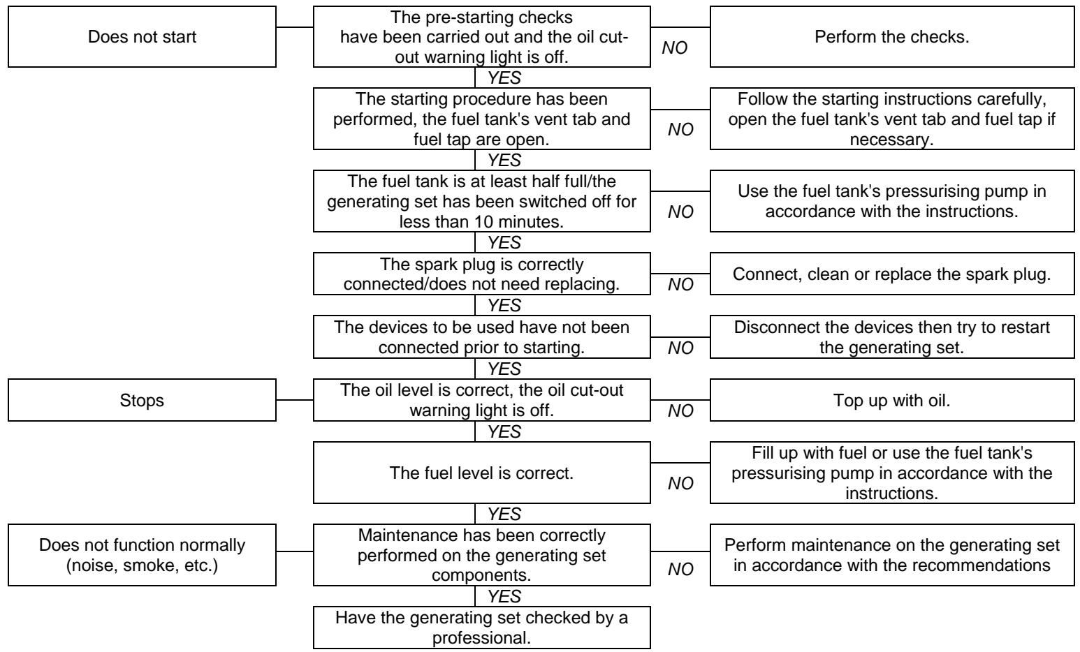
7. Diagnostics for minor faults
The generating set...
Check that:
Solutions to be applied:

8. Technical specifications
8.1. Operating conditions
The stated outputs of the generating sets are obtained under the reference conditions outlined in ISO 8528-1(2005):
Total barometric pressure: 100kPa - Ambient air temperature: 25^ (298 K) - Relative humidity: 30% .
Generating set performance is reduced by approximately 4% for every additional 10^ and/or approximately 1% for every additional 100m in altitude. Generating sets can only operate while stationary.
8.2. Capacity of the generating set (overload)
Before connecting and operating the generating set, calculate the electrical power required by the devices to be used (in watts)*. When running several devices simultaneously, never exceed the rated load of the generating set (in amps and/or watts) when it is operating continuously.
*This load is usually indicated in the technical specifications or on the device manufacturer's plate. Some devices require a higher load when starting. This minimum required power must not exceed the generating set's maximum power.
8.3. Specifications
| Equipment model | VARIO 1000i | VARIO 2000i | VARIO 3000i |
| Rated/maximum power | 900 W / 720 W | 1850 W / 1480 W | 2400 W / 2000 W |
| Acoustic pressure level at 1 m (LpA) / measurement uncertainty | 79 dB(A) / 0,70 dB(A) | 80 dB(A) / 0,70 dB(A) | 82 dB(A) / 0,70 dB(A) |
| Engine type | OLYMP ES 38-1 | OLYMP ES 100-1 | OLYMP ES 128-1 |
| Recommended fuel/fuel tank capacity | Unleaded petrol (SP95-E10 ; -E15 ; -E85 prohibited) / 1,6 L | Unleaded petrol (SP95-E10 ; -E15 ; -E85 prohibited) /2.8 L | Unleaded petrol (SP95-E10 ; -E15 ; -E85 prohibited) / 3,4 L |
| Recommended oil/oil sump capacity | SAE 15W40 / 0,15 L | SAE 15W40 / 0,5 L | SAE 15W40 / 0,55 L |
| Oil cut-out* | Yes | Yes | Yes |
| Alternating current / Direct current | 230 V – 3,2 A | 230 V – 6,4 A / 12V-5A | 230 V – 8,7 A / 12V-5A |
| Circuit breaker** | Yes | Yes | Yes |
| Socket type | 1 x 10/16 A – 230 V | 2 x 10/16 A – 230 V + 1 x 10 A - 12 V | 2 x 10/16 A – 230 V + 1 x 10 A - 5 V |
| Spark plug/battery type | NGK : CR7HSA - LG : A7RTC / No | NGK : BPR7HSA - LG : E7RTC / No | NGK : BPR6ES / Yes |
| Dimensions I x w x h | 44,8 x 24,8 x 37,5 cm | 53 x 28,5 x 45 cm | 56,5 x 30 x 46,6 cm |
| Weight (without fuel) | 12.5 kg | 20 kg | 22.5 kg |
This generating set complies with directive 97/68/CE on pollutant emissions.
*Oil cut-out: If there is no oil in the engine sump or if the oil pressure is low, the oil cut-out automatically stops the engine to prevent any damage. If this occurs, check the engine oil level and top it up if necessary before looking for any other cause of the problem.
**Circuit breaker: The genset's electrical circuit is protected by one or more magnetothermal, differential or thermal cut-out switches. In the event of an overload and/or short circuit, the supply of electrical energy may be cut.
If necessary, replace the circuit breakers in the generating set with circuit breakers with identical nominal ratings and specifications.
8.4. EC Declaration of conformity
Name and address of manufacturer :
SDMO Industries - 12 bis rue de la Villeneuve - CS 92848 -
29228 BREST Cedex 2 - France.
Name and address of the person authorised to create and keep the technical file
L. Courtès - SDMO Industries - 12 bis rue de la Villeneuve - CS 92848 - 29228 BREST Cedex 2 - France.
| Product description : | Make : | Type : | Serial numbers: |
| Generating set | SDMO | 3499231001035 | 2012-610-000001 > 2016-610-999999 |
| 3499231001042 | 2012-620-000001 > 2016-620-999999 | ||
| 3499231001059 | 2012-630-000001 > 2016-630-999999 |
L. Courtès, the manufacturer's authorised representative, hereby declares that the product conforms to the following EU Directives:
2006/42/EC Machinery Directive ; 2006/95/EC Low Voltage Directive ; 2004/108/EC Directive on Electromagnetic Compatibility ;
2000/14/EC Directive relating to the Noise Emission of Outdoor Equipment.
| For the directive 2000/14/EC : | ||||
| Notified body : | Notified body : | Notified body : | Notified body : | Notified body : |
| CETIM - BP 67-F60304 - SENLIS | Appendix VI. | 92,5 dB(A) | 93 dB(A) | 720 W |
| 94,5 dB(A) | 95 dB(A) | 1480 W | ||
| 94,5 dB(A) | 95 dB(A) | 2000 W | ||
Brest, 01/12/2012
L. Courtes, Assistant Director, Design and Projects.
29228 BREST Cedex 2 - France.
CS 92848 - 29228 BREST Cedex 2 - France.
| Descrição do equipoamento: | Marca: | Tipo: | Númos de série: |
| Grupo electrogéneo | SDMO | 3499231001035 | 2012-610-000001 > 2016-610-999999 |
| 3499231001042 | 2012-620-000001 > 2016-620-999999 | ||
| 3499231001059 | 2012-630-000001 > 2016-630-999999 |
29228 BREST Cedex 2 - France.
(C):ГараHTMnPoBaHHbIy yPOBeHb aKvCTNHeCKOMLUHOCTN
(J): HanpääkeHne Toka
(D): MakcimalbHaM MOUHOCTb
(K): INHdeKc 3aunTbI
(E):HOMInHaJIbHaJa MOUHOCTb
(L): OchoBHO CTaHdapt
(F):Ko3dcbmLHeHMTMOUHOCTN:
(M): CepinHbI Homep
(G): Macca
CepnHbIe Homepa 6ydyT Tpe6oBaTbc npu yctpaHeHm HeNCpPaBHOCTe nIIN npn 3aKa3e 3aNaChbIX aCtei.
YtobixcoxpaHb,3aIIuHte Hnke cepHbIe Homepa reHepaTOPHOyCTaHOBKn nDbIrataJIa.
CepinHbI HOMep rehepaTOpHOyCTaHOBKn:
Mapka DvuraTeJIa:
CepinHbI HOMep DnBraTeJIa: (Ppumep: Kohler (CEPNHbI N 4001200908))
5.3.6 OuInctka reHepaToPHOyCTaHOBKN

BHIMMAHNE
3anpeetaetcMbIbrehepatopHyu yCTaHOBky cTpye BODbl NOd daBHeHem IIN C NOMOJIbU BbICOKHaOpHO MOeHOny yCTaHOBKN.
1 YdaJIte nbIb n MycOp n3 30Hb BO3Je rIyUHTeY CnCTeMb bBInycka oTpa6oTaBux ra3OB (A-14).
MoTe rHepatopHyU yCTAHOBky CHaPyKl C NOMOUsIy6Kn BODOn C DoabHneHm MAnKO RcEpdCTBa (HaPIMep, LAmNpyIra MoIKn ABTomOuIne). Bo3MoxHo makKe uCnONb3OeaHue MOoSeu ay6ku C nocNeuyouum EblupaHuem Maeko EnumbIaeaue bemooBIO.
PombBaIe YnCTOBo BDOJ C NOMOsbHry6Kn, YTObblYCTpaHnTB BCE cIeBb MOUoero CpeDCTBa.
6. TpaHcnpTnpoBka n XpaHeHne reHepaTopHou yCTaHOBKn
6.1. YcnoBna TpaHcnpTnpoBkn N TaKeJaXhbIX pa6OT
IpeeTpaHcnpToBOKo rHepeaTopHO uCTaHOBKn npOBePbTe 3aTgKy pe3b60bIX CoeHNHeH, 3akpoTte TOnJIbHbI KpaH (pni HauHn) n OTKIOUHTe akymyTAOPHyO 6aTaPeEO (pri HaNUn). IehepaTopHa YcTaHOBKa DoJXHa nepeBO3ntbc R B ee HopMaJIbHOM pa6Ochem NIOJKeHH, 3aPpeuaetcra YKlaDbIBaTb eE Ha 6ok. IepemeueHne yCtahOBKn doJXHo ocUxctBnTbc C OCTOpOxHocTBIO n 6e3 pbIKOB, MeTO dIy XpaEHn IIN 3KcPnyatauIN DoJXHO 6blTb NOdTOTBNeHO ppeBaPntelHO.
6.2.YCJIOBnaXpaHEnHa
OncnBie Oepaunno nndroTobK K xpaehHIO cneJyET BbIOnHHTb, ecnn PnaHpyETc, YTO rehepatopnag yctahOBKa He bdyet NcNtB3oBaTbC 60nee 2 MecaueB mHee 1 rda. B cyuae 60nee DInTeBHorO xpaehHnpeKomeHnyETc OpaTITbC K bInKaIeMy npedCTaBteLIO qinPmbln EkeRdoHO 3aynckatB rehepatopHyIO yctahOBky B paBOTy Ha HeckonbKO uacOB I 3aTEM BbIOnHHTb Oepaunn NOCTAHOBKn H xpaHene. 3Ta onepaunr Tpe6yET 3aINBkBn B TOINIBhBn Bak KOHcebpUIOe IOabAKN ININ POHORO CnBA TOINIBa N3 baka (npedymatpmbte drr 3TOr HOadHexaLyU oMKocTb).
1 OtkpoTe JIOUOK DOCTyna.
2 PnrirotOBuHnAeJkaUcE MKOCTb H He 3aKpbIbA ToNIIBbI KpaH, OTKpoJIe TPOBky TOINIBHO6aKa N I3BLeKITE TOINIBHbIΦIbTp.
3ДаTe TOnJIbBy NOJIHOCTbO CTeMb E MKOcTb (CINB 6aKa N TOIINBONPOBOIOB), 3aTEM yCTaHOBnTE Ha MeCTO HOBbI TOIINBHyΦIbTp.
3aKpOte npo6ky TOnnBHO 6aka, yCTaHObTe yCTPOcTB OBeHTnJIaUN B NIOJXeHne 'ON' n IcNoJIb3yIte cTAPTE (noJoxHeN e), YTObI 3anyCTntb rHepaTOphyU yCTaHObky. Ocmaebme deuameNB paobommb do ocmaHO6ku u3-3a ebipabomku monnuea.
3akpoTe TOnJIINBbI KpaH u yCTpoiCTBO BeHTnJIaCm (OFF), ydaJIte CJeDbI ToJIINBa u ybeJInTeCb B OTCyTCTBn yTeueK.
5 Ha TeJIOM DbIgATEJe 3aMeHInTe MOTOpHOe MaCJO.
OTkpOte KpbIuKy DoCTyna K CBeue, ChIMnTe ee (E-2) n 3aJIeTb B cIINHdp npImepHO 3 Ml (1 cToIOBHy JOxKky) YNCTOROMOTOPHOro Macna Upe3 CBeUHOe OTBepCTne; 3aTEM yCTaHOBnTE CBeuy Ha MeCTO n 3akpoTe KpbIuKy DoCTyna.
7 IotyHnTe 3-4 pa3a pyKoTky UHypoboro cTapTepa (A-7), yTo6bl paCnpedeNtB macNo no CUNINHpam dIy npedOTbpaueHn Kopp0nn.
OuHCTnTe nIIN 3aMeHnTE BO3dyuHbI ΦnJIbTp (B 3aBcHmOCTn OT eRO COCToHn) I 3akPoTe JIOUOK DOCTyna.
OuHCTnTe rHepeaTopHyU yCTaHOBky HnakpoTe ee YexNOM dIy 3aunTbI OT nbJIN.
XpaHnTe reHepaTopHyO yCTaHOBky B uNCTOM, cyXOM MeCTe. He xpaHnTe reHepaTopHyO yCTaHOBky yIOxKeHHoHa 60K.
7.Диагнoctик He3HaUNTeJIbHbIX HeNCnPaBHOCTe

8. Texhnueckne ycNoBnA
8.1.YcnoBna3KcnnyaTaun
3aBHeHHbIe XapaKTePncTnIKr HeHepaToPbHbIX yCTaHOBOK NIOUyeHbI B KOHTpOJIbHbIX YCIOBmX B COOTBeTCTBmN CO CTaHdApTOM ISO 8528-1(2005):
XapaKTepeTcNk rHePapToHoi yCTaHOBKn cHnKaOTc npImepHo Ha 4% npu yBeJIueHm TempeAtpybHa KaJDbie 10°C n/nn npimepHo Ha 1% npu yBeJIueHm BlicOtbl Na yPOBHeM MOpra Ha KaJDbie 100 m. TehepApToHbIe yCTaHOBKn MoYr pa6oTaTb TOnbKO B cTaIOHOAPbIX yCNoBnX.
8.2. MoiHocTb reHepaTopHO yCTaHOBKn (neperpy3ka)
Ipeedn odkluohem m npckom B paobTy reheapotnoy yctahOBKn BbyHCNIte 3neKtpnueCKyIO MOUHOCb, Heo6xoNDmyIO nIITaHnI NCNoJIb3yeMbIX npi6bpOB (BbypaKeHHyIO B BATTax)*. Cymmnapna MoUHocTb (B amNepax INIIN BaTTax) OndHOBPMeHNO IcNoJIb3yeMbIX npi6bpOB He doJnxHa npebblaTb HOMHaJIbHyIO MOUHOCb reheapotnoy yCTAHOBKn npu ee HnpepbIBHO paOte. *3ma 3neKmpueckra MoUHOCmb oblyho yka3bIeaemc8 mexHuueckux xapaKmepcUmkaX unu Ha 3a0dckou ma6nuek npubopoe. HekomopbIe npu6bpbl mpebyom noBbiueHHyIO MoUHOCmb b MOMehm ux pycKa e paOmy. 3ma MuHumalnbnaMpe6yema MoUHOCmb He doJnxHa npeblawmb MaKcMaJIbHyIO MoUHOCmb aeHepamOpHO ycmaHo8ku.
8.3. XapakTepeNCTIKN
(C):mitattumelutehotaso
(J): virran jannite
(D): enimmästeho
(K): sujoausindeksi
(E): nimellisteho
(L): viitenormi
(F): tehokerroin
(M): sarjanumero
(G): massa
29228 BREST Cedex 2 - France.
CS 92848 - 29228 BREST Cedex 2 - France.
| Koneiston kuvaus: | Merkki: | Tyyppi: | Sarjanumerot: |
| Generaattorikoneisto | SDMO | 3499231001035 | 2012-610-000001 > 2016-610-999999 |
| 3499231001042 | 2012-620-000001 > 2016-620-999999 | ||
| 3499231001059 | 2012-630-000001 > 2016-630-999999 |
29228 BREST Cedex 2 - France.
Ovopa kai dieuovan tou arouou eouoiootnevou yia tnv Karapion kai Tnv katoxntou texviokou qakelou
L. Courtès - SDMO Industries - 12 bis rue de la Villeneuve -
CS 92848 - 29228 BREST Cedex 2 - France.
29228 BREST Cedex 2 - France.
CS 92848 - 29228 BREST Cedex 2 - France.
| Popis vybavení: | Značka: | Typ: | Sériová Čísla: |
| Elektrocentrála | SDMO | 3499231001035 | 2012-610-000001 > 2016-610-999999 |
| 3499231001042 | 2012-620-000001 > 2016-620-999999 | ||
| 3499231001059 | 2012-630-000001 > 2016-630-999999 |
29228 BREST Cedex 2 - France.
Tās personas vards un adrese, kurai ir tiesibas izveidot un tutē tehnisko lietu
L. Courtès - SDMO Industries - 12 bis rue de la Villeneuve -
CS 92848 - 29228 BREST Cedex 2 - France.
| Izstrādājuma apraksts : | Izgatavotāja zīme: | Tips : | Sērijas numuri: |
| Generatoragregāts | SDMO | 3499231001035 | 2012-610-000001 > 2016-610-999999 |
| 3499231001042 | 2012-620-000001 > 2016-620-999999 | ||
| 3499231001059 | 2012-630-000001 > 2016-630-999999 |
29228 BREST Cedex 2 - France.
29228 BREST Cedex 2 - France.
Ime in naslov osebe pooblascene za ustvaranje ih hrambo tehnicne datoteke
L. Courtès - SDMO Industries - 12 bis rue de la Villeneuve -
CS 92848 - 29228 BREST Cedex 2 - France.
| Opis materiala: | Proizvajalec: | Tip: | Številke serije: |
| Generator | SDMO | 3499231001035 | 2012-610-000001 > 2016-610-999999 |
| 3499231001042 | 2012-620-000001 > 2016-620-999999 | ||
| 3499231001059 | 2012-630-000001 > 2016-630-999999 |
1. MODALITES ET CONDITIONS D'APPLICATION DE LA GARANTIE
Your generating set is covered by a commercial warranty granted by SDMO Industries in accordance with the following provisions.
The warranty period for your generating set shall last for a term of two (2) years or one hundred and fifty (150) hours of operation, whichever occurs first and starting from the date of purchase. The warranty must be executed by the distributor from whom you purchased your generating set. In the event of a problem with your generating set, you are requested by SDMO Industries to contact the distributor and present your purchase invoice or, where applicable, the After Sales Service of SDMO Industries on the following number: +33298414141. The Customer Services Department of SDMO Industries is available to answer any questions you may have regarding the application of the guarantee; contact details are as follows: SDMO INDUSTRIES -12, Bis rue de la Villeneuve - CS 92848 - 29228 Brest Cedex 2 - Tel: +33298414141 - Fax: +33298416307 -www.sdmo.com.
1. TERMS OF THE WARRANTY
The warranty commences on the date of first purchase of the generating set. The warranty is transferred with the generating set when it is assigned by the first user, with or without financial consideration, and for the remaining term of the initial warranty which cannot be extended. The warranty is only valid on presentation of a legible purchase invoice on which is stated the date of purchase, the type of generating set, the serial number, and which includes the distributor's name, address and company stamp. SDMO Industries reserves the right to refuse to honour the warranty in the absence of documentary evidence of the date and place of purchase of the generating set.
This warranty confers the right to the repair or replacement of the generating set or any of its components judged to be faulty by SDMO Industries following evaluation in its workshops; SDMO Industries reserves the right to meet its obligations by modifying any of the generating set's devices. The generating set or component(s) replaced under warranty become the property of SDMO Industries.
2. LIMITATIONS OF THE WARRANTY
The warranty applies to generating sets which have been installed, operated and maintained in accordance with the documentation supplied by SDMO Industries and, in the case of a generating set malfunction, when this is due to faulty design, manufacture or materials. SDMO Industries does not guarantee the performance levels of the generating set, nor its operation or reliability, for any specific purpose. Under no circumstances can SDMO Industries be held responsible for any consequential loss, whether or not arising out of material damage, such as and in particular, but not exclusively: operating losses, expenses or other costs of whatever nature, as a result of the non-availability of the generating set. The warranty is limited to costs associated with the repair or replacement of the generating set or any of its components, excluding consumables. The warranty therefore covers the cost of parts and labour, excluding travelling expenses. Transportation costs of the generating set or of any of its components to SDMO INDUSTRIES workshops, or to any of its approved agents, are the responsibility of the Customer; "return" transportation costs will be paid for by SDMO Industries. However, in the case of the warranty not being honoured, all transportation costs are to be paid by the Customer.
3. WARRANTY EXCLUSION
Warranty exclusion applies in the following cases: damage caused during transportation of the generating set; incorrect installation or installation not complying with SDMO Industries recommendations and/or technical and safety standards; use of non-recommended products, components, replacement parts, fuel or lubricants; incorrect or abnormal use of the generating set; modification or conversion of the generating set or any of its components not authorised by SDMO Industries; normal wear and tear of the generating set or any of its components; damage caused by negligence, lack of supervision, maintenance or cleaning of the generating set; force majeure, acts of God or other external causes (natural disaster, fire, impact, flooding, lightning, etc.); operating of the generating set with insufficient charge; inadequate storage conditions of the generating set. The following components are also excluded from the warranty: exhausts, fuel supply circuits and systems located upstream of fuel/carburettor/injector filters, AVR, starting systems (batteries, starters, recoil starters), enclosures, filters, pipes and hoses, seals and gaskets, belts, relays, fuses, push buttons, bulbs, diodes, switches, sensors (fluid levels, pressure, temperature, etc.), measurement indicators and all consumables and wearing parts. This warranty is also excluded within the scope of professional use and/or for rental purposes of the generating set.
4. LEGAL PROVISIONS
This warranty falls under French law and does not exclude the benefit of the legal warranty, in accordance with the provisions of articles L211-4 et seq. of the Consumer Code and articles 1641 et seq. of the Civil Code.
Consumer Code
"Article L.211-4: The Vendor is required to deliver goods that comply with the contract and is answerable for any non-compliances existing on delivery. It is also answerable for any non-compliances resulting from packing and from assembly or installation instructions when it has been put in charge of those operations by the contract or they have been carried out under its responsibility." 20
"Article L.211-5: To comply with the contract, the goods must:
-
Be suitable for the use customarily expected of similar goods and, if applicable, must:
-
match the description given by the Seller and possess the qualities that the Seller has presented to the Buyer in the form or a sample or model;
have the qualities a buyer can legitimately expect, considering the public statements made by the Vendor, the producer or its representative, particularly in its advertising or labelling;
- Or present the characteristics mutually defined by the parties or be suitable for any special purpose desired by the Purchaser which has been made known to the Vendor and which the Vendor has accepted.
"Article L.211-12: Action arising from a non-compliance is time-barred for two years after delivery of the goods."
Civil Code
Article 1641: The Vendor is bound by the guarantee for any hidden defects in the thing sold which make it unsuitable for its intended purpose or which reduce that use so much that the Purchaser would not have acquired it or would have paid only a smaller price for it if it had been aware of it.
"Article 1648: The acquirer must instigate action resulting from redhibitory defects within two years of discovering the defect."
GARANTÍA COMERCIAL

3. MIDA GARANTII E I HOLMA
3. ANULOWANIE GWARANCJI
- Generating set identification
- Instructions and safety regulations (personal protection)
- General guidelines
- Selecting the connection cables (cable cross section)
- Guidelines for protecting the environment
- Getting started with the generating set
- Key to illustrations
- Initial commissioning
- Positioning the generating set for operation
- Check the generating set is in a good general condition (bolts, hoses)
- Checking the engine oil level and topping up
- Checking the fuel level and topping up
- Starting the generating set
- Use the tank's pressurising pump
- Using the electricity supplied
- Use the MAX-ECO mode
- Switching the generating set off
- Generating set maintenance
- Reminder of use
- Top up the oil
- Dry clogging:
- Moist/oily clogging:
- Clean or replace the spark plug
- Cleaning the generating set
- Transporting and storing the generating set
- Transport and handling conditions
- Storage conditions
- Diagnostics for minor faults
- Technical specifications
- Operating conditions
- Capacity of the generating set (overload)
- Specifications
- EC Declaration of conformity
- OuInctka reHepaToPHOyCTaHOBKN
- TpaHcnpTnpoBka n XpaHeHne reHepaTopHou yCTaHOBKn
- YcnoBna TpaHcnpTnpoBkn N TaKeJaXhbIX pa6OT
- 6.2.YCJIOBnaXpaHEnHa
- 7.Диагнoctик He3HaUNTeJIbHbIX HeNCnPaBHOCTe
- Texhnueckne ycNoBnA
- 8.1.YcnoBna3KcnnyaTaun
- MoiHocTb reHepaTopHO yCTaHOBKn (neperpy3ka)
- MODALITES ET CONDITIONS D'APPLICATION DE LA GARANTIE
- TERMS OF THE WARRANTY
- LIMITATIONS OF THE WARRANTY
- WARRANTY EXCLUSION
- LEGAL PROVISIONS
- Consumer Code
- Civil Code
- GARANTÍA COMERCIAL
- MIDA GARANTII E I HOLMA
- ANULOWANIE GWARANCJI
Brand : SDMO
Model : VARIO 2000I
Category : Generator