AD2550-ITX - Carte mère ASROCK - Free user manual and instructions
Find the device manual for free AD2550-ITX ASROCK in PDF.
Download the instructions for your Carte mère in PDF format for free! Find your manual AD2550-ITX - ASROCK and take your electronic device back in hand. On this page are published all the documents necessary for the use of your device. AD2550-ITX by ASROCK.
USER MANUAL AD2550-ITX ASROCK
No part of this installation guide may be reproduced, transcribed, transmitted, or trans- lated in any language, in any form or by any means, except duplication of documentation by the purchaser for backup purpose, without written consent of ASRock Inc.
Products and corporate names appearing in this guide may or may not be registered trademarks or copyrights of their respective companies, and are used only for identifica- tion or explanation and to the owners’ benefit, without intent to infringe.
Specifications and information contained in this guide are fumished for informational use only and subject to change without notice, and should not be constructed as a commit- ment by ASRock. ASRock assumes no responsibility for any errors or omissions that may appear in this guide.
With respect to the contents of this guide, ASRock does not provide warranty of any kind, either expressed or implied, including but not limited to the implied warranties or condi- tions of merchantabilty or fitness for a particular purpose. In no event shall ASRock, its directors, officers, employees, or agents be liable for any indirect, special, incidental, or consequential damages (including damages for loss of profits, loss of business, loss of data, interruption of business and the like), even if ASRock has been advised of the pos- sibility of such damages arising from any defect or error in the guide or product.
FE This device complies with Part 15 of the FCC Rules. Operation is subject to the following two conditions: (1) this device may not cause harmful interference, and (2) this device must accept any interference received, including interference that may cause undesired operation.
CALIFORNIA, USA ONLY The Lithium battery adopted on this motherboard contains Perchlorate, a toxic substance controlled in Perchlorate Best Management Practices (BMP) regulations passed by the Califomia Legislature. When you discard the Lithium battery in California, USA, please follow the related regulations in advance.
“Perchlorate Material-special handling may apply, see www dtsc.ca.gov/hazardouswaste/perchlorate"
ASRock Website: http:/www.asrock.com
Published March 2013 Copyright©2013 ASRock INC. All rights reserved.
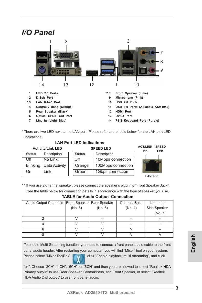
*3 LAN RJ45 Port 10 USB 20 Ports 4 Central / Bass (Orange) 11. USB 3.0 Ports (ASMedia ASM1042) 5 Rear Speaker (Black) 12. HDMI Port 6 Optical SPDIF Out Port 13. DVD Port T° Line In (Light Blue) 14. PSI2 Keyboard Port (Purple)
* There are two LED next to the LAN port. Please refer to the table below for the LAN port LED indications.
LAN Port LED Indications
Activity/Link LED SPEED LED st Ven atus | Descripiion Taius Description Of No Link Of TOMbps connection Blinking| Data Activity | | Orange | 100Mbps connection On Dnk Green | 1Gbps connection LAN Port
** If you use 2-channel speaker, please connect the speakers plug into “Front Speaker Jack”. See the table below for connection details in accordance with the type of speaker you use. TABLE for Audio Output Connection
Audio Output Channels [Front Speaker| Rear Speaker | Central/Bass | Line ln or (No. 8) (No. 5) (No. 4) Side Speaker (No. 7) 2 V — — E 4 A v _ _ 6 V v v =
E V V V V To enable Multi-Streaming function, you need to connect a front panel audio cable to the front panel audio header. After restarting your computer, you will find “Mixer” tool on your system. Please select ‘Mixer ToolBox" 73 , dick “Enable playback multi-streaming”, and click
“ok. Choose “2CH", *4CH', “CH”, or *BCH' and then you are allowed to select “Realtek HDA Primary output” to use Rear Speaker, Central/Bass, and Front Speaker, or select “Realtek HDA Audio 2nd output” to use front panel audio.
Thank you for purchasing ASRock AD2550-ITX motherboard, a reliable mother- board produced under ASRock's consistently stringent quality control. It delivers excellent performance with robust design conforming to ASRock's commitment to quality and endurance.
This Quick Installation Guide contains introduction of the motherboard and step-by- step installation guide. More detailed information of the motherboard can be found in the user manual presented in the Support CD.
Because the motherboard specifications and the BIOS software might be / updated, the content of this manual will be subject to change without no- tice. In case any modifications of this manual occur, the updated version will be available on ASRock website without further notice. You may find the latest VGA cards and CPU support lists on ASRock website as well. ASRock website _htip2/www.asrock.com
If you require technical support related to this motherboard, please visit our website for specific information about the model you are using.
www.asrock.com/support/index.asp
Platform = Mini-ITX Form Factor: 6.7-in x 6.7-in, 17.0 cm x 17.0 cm - AI Solid Capacitor design
Chipset - Southbridge: Intel? NM10 Express
- Supports DDR3 1066/800 non-ECC, un-buffered memory - Max. capacity of system memory: 4GB (see CAUTION 1)
- DirectX 9.0, Pixel Shader 3.0
- Three VGA Output options: D-Sub, DVI-D and HDMI (see CAUTION 2)
- Supports HDMI 1.3a Technology with max. resolution up to 1920x1200
- Supports DVI with max. resolution up to 1920x1200 @ 60HA
- Supports D-Sub with max. resolution up to 1920x1200 @ 60Hz
- Supports HDCP function with DVI and HDMI ports
- Supports Full HD 1080p Blu-ray (BD) / HD-DVD playback with DVI and HDMI ports
= 7.1 CH HD Audio with Content Protection (Realtek ALC892 Audio Codec) - Premium Blu-ray audio support
= PCIE x Gigabit LAN 10/10/1000 Mbys - Realtek RTL8111E
- Supports Wake-On-LAN
- Supports LAN Cable Detection
- Supports Energy Efficient Ethernet 802.3az
- Supports PXE Rear Panel 1/0
- HD Audio Jack: Rear Speaker/Central/Bass/Line in/Front Speaker/Microphone
- 2 x SATA 3.0 Gb/s connectors, support NCQ, AHCI and Hot Plug functions
- 1 x COM port header
- 1 x CPU Fan connector (3-pin)
- 1 x Chassis Fan connector (3-pin)
- 1 x 24 pin ATX power connector
- 1 x Front panel audio connector
- 2x USB 2.0 headers (support 4 USB 2.0 ports)
- 16Mb AMI UEFI Legal BIOS with GUI support - Supports “Plug and Play”
- ACPI 1.1 Compliance Wake Up Events
- Supports jumperfree
- SMBIOS 2.3.1 Support
- CPU/Chassis Quiet Fan
- Voltage Monitoring: +12V, +5V, +3.3V, CPU Vcore
- Microsoft” Windows® 7 32-bit compliant * Due to lack of Intel® 64-bit VGA driver support, this motherboard does not support 64-bit OS.
- FCC, CE, WHQL - ErP/EuP Ready (ErP/EuP ready power supply is required)
* For detailed product information, please visit our website: http:/www.asrock.com
ASRock AD2550-ITX Motherboard
WARNING Please realize that there is a certain risk involved with overclocking, including adjusting the setting in the BIOS, applying Untied Overclocking Technology, or using the third-party overclocking tools. Overclocking may affect your system stability, or even cause damage to the components and devices of your system.
It should be done at your own risk and expense. We are not responsible for possible damage caused by overclocking.
1... Due to the chipset limitation, the actual memory size may be less than 4GB for the reservation for system usage under Windows® OS.
2. You can choose to use two of the three monitors only. D-Sub, DVI-D and HDMI monitors cannot be enabled at the same time. Besides, with the DVI-t0-HDMI adapter, the DVI-D port can support the same features as HDMI port.
ASRock AD2550-ITX Motherboard
ASRock Instant Boot allows you to turn on your PC in just a few seconds, provides a much more efficient way to save energy, time, money, and improves system running speed for your sys- tem. It leverages the S3 and S4 ACPI features which normally enable the Sleep/Standby and Hibernation modes in Windows® to shorten boot up time. By calling S3 and S4 at specific timing during the shutdown and startup process, Instant Boot allows you to enter your Windows® desktop in a few seconds.
ASRock Instant Flash ASRock Instant Flash is a BIOS flash utility embedded in Flash ROM. This convenient BIOS update tool allows you to update system BIOS without entering operating systems first like MS- DOS or Windows®. With this utility, you can press the <F6> key during the POST or the <F2> key to enter into the BIOS setup menu to access ASRock Instant Flash. Just launch this tool and save the new BIOS fille to your USB flash drive, floppy disk or hard drive, then you can update your BIOS only in a few clicks without preparing an additional floppy diskette or other compli- cated flash utility. Please be noted that the USB flash drive or hard drive must use FAT32/16/12 file system.
ASRock APP Charger If you desire a faster, less restricted way of charging your Apple devices, such as iPhone/iPad/iPod Touch, ASRock has prepared a wonderful solution for you - ASRock APP Charger. Simply install the APP Charger driver, it makes your iPhone charge much quickly from your computer and up to 40% faster than before. ASRock APP Charger allows you to quickly charge many Apple devices simultaneously and even supports continu- ous charging when your PC enters into Standby mode (S1), Suspend to RAM (S3), hibemation mode (S4) or power off (S5). With APP Charger driver installed, you can easily enjoy the mar- velous charging experience.
ASRock AD2550-ITX Motherboard
ASRock XFast USB ASRock XFast USB can boost USB storage device perfor- mance. The performance may depend on the properties of the device.
ASRock XFast LAN ASRock XFast LAN provides a faster internet access, which includes the benefits listed below. LAN Application Prioritiza- tion: You can configure your application's priority ideally and/or add new programs. Lower Latency in Game: After setting online games priority higher, it can lower the latency in games. Traffic Shaping: You can watch Youtube HD videos and download si- multaneously. Real-Time Analysis of Your Data: With the status window, you can easily recognize which data streams you are transferring currently.
ASRock XFast RAM ASRock XFast RAM is a new function that is included into AS- Rock Extreme Tuning Utility (AXTU). It fully utilizes the memory space that cannot be used under Windows® OS 32-bit CPU. ASRock XFast RAM shortens the loading time of previously visited websites, making web surfing faster than ever. And it also boosts the speed of Adobe Photoshop 5 times faster. An- other advantage of ASRock XFast RAM is that it reduces the frequency of accessing your SSDs or HDDs in order to extend their lifespan.
ASRock On/Off Play Technology ASRock On/Of Play Technology allows users to enjoy the great audio experience from the portable audio devices, such like MP3 player or mobile phone to your PC, even when the PC is turned off (or in ACPI S5 mode)! This motherboard also provides a free 3.5mm audio cable (optional) that ensures users the most convenient computing environment.
ASRock AD2550-ITX Motherboard
This is a Mini-ITX form factor (6.7" x 6.7", 17.0 x 17.0 cm) motherboard. Before you install the motherboard, study the configuration of your chassis to ensure that the motherboard fits into it.
j Make sure to unplug the power cord before installing or removing the
motherboard. Failure to do so may cause physical injuries to you and damages to motherboard components.
2.1 Screw Holes Place screws into the holes indicated by circles to secure the motherboard to the chassis.
j \ Do not over-tighten the screws! Doing so may damage the motherboard.
2.2 Pre-installation Precautions Take note of the following precautions before you install motherboard components or change any motherboard settings.
1. Unplug the power cord from the wall socket before touching any component. 2. To avoid damaging the motherboard components due to static electricity, NEVER place your motherboard directly on the carpet or the like. Also remember to use a grounded wrist strap or touch a safety grounded object before you handle components. 3. Hold components by the edges and do not touch the ICs. 4. Whenever you uninstall any component, place it on a grounded antistatic pad or in the bag that comes with the component. 0 Before you install or remove any component, ensure that the power is switched off or the power cord is detached from the power supply. Failure to do so may cause severe damage to the motherboard, peripherals, and/or components.
ASRock AD2550-ITX Motherboard
2.3 Installation of Memory Modules (SO-DIMM)
AD2550-ITX motherboard provides two 204-pin DDR3 (Double Data Rate 3) SO- DIMM slots.
slot; otherwise, this motherboard and SO-DIMM may be damaged: 2. Please install the memory module from DDR3_A2 slot for the first priority.
A 1. Itis not allowed to install a DDR or DDR2 memory module into DDR3
L Installing a SO-DIMM
À / Please make sure to disconnect power supply before adding or L removing SO-DIMMS or the system components.
Step 1. Unlock a SO-DIMM slot by pressing the retaining clips outward. Step 2. Align a SO-DIMM on the slot such that the notch on the SO-DIMM matches the break on the slot.
The SO-DIMM only fits in one correct orientation. It will cause perma- nent damage to the motherboard and the SO-DIMM if you force the SO- DIMM into the slot at incorrect orientation.
Step 3. Firmly insert the SO-DIMM into the slot until the retaining clips at both ends fully snap back in place and the SO-DIMM is properly seated.
11 ASRock AD2550-ITX Motherboard
2.4 Expansion Slot (PCI Slot) There is 1 PCI slot on this motherboard.
The PCI slot is used to install expansion card that has the 32-bit PCI interface.
Installing an expansion card
Before installing the expansion card, please make sure that the power supply is switched off or the power cord is unplugged. Please read the documentation of the expansion card and make necessary hardware settings for the card before you start the installation.
Remove the system unit cover (if your motherboard is already installed in a chassis).
Remove the bracket facing the slot that you intend to use. Keep the screws for later use.
Align the card connector with the slot and press firmly until the card is completely seated on the slot.
Fasten the card to the chassis with screws.
Replace the system cover.
ASRock AD2550-ITX Motherboard
2.5 Pin Header Easy Installation Guide
ASRock motherboard is equipped with pin headers with obvious colors which indi- cate you to recognize the crucial headers more easily. Please refer to below illustra- tions for the pin definition of onboard headers. If you want to have more information
about the usage of these headers, please refer to “Jumpers Setup" and “Onboard Headers and Connectors* for details.
USB_PWR USB 2.0 Header
2.6 Jumpers Setup The illustration shows how jumpers are setup. When the jumper cap is placed on
pins, the jumper is “Short”. If no jumper cap Lai
is placed on pins, the jumper is “Open”. The
illustration shows a 3-pin jumper whose GG LT LEE pini and pin2 are “Short’ when jumper cap short Open
is placed on these 2 pins.
Jumper Setting Description Clear CMOS
(CLRCMOS1, 2-pin jumper)
(see p2 No. 13) 2-pin jumper
Note: CLRCMOS1 allows you to clear the data in CMOS. The data in CMOS in- cludes system setup information such as system password, date, time, and system setup parameters. To clear and reset the system parameters to de- fault setup, please turn off the computer and unplug the power cord from the power supply. After waiting for 15 seconds, use a jumper cap to short 2 pins on CLRCMOSH for 5 seconds.
ASRock AD2550-ITX Motherboard
2.7 Onboard Headers and Connectors
Onboard headers and connectors are NOT jumpers. Do NOT place jumper caps over these headers and connectors. Placing jumper caps
over the headers and connectors will cause permanent damage of the
These two Serial ATA2 (SATA2) connectors support SATA data cables for internal storage devices. The current SATA2 interface allows up to 3.0 Gb/s data transfer rate.
Serial ATA (SATA) Data Cable (Optional)
Either end of the SATA data cable can be connected to the SATA / SATA2 hard disk or the SATA2 connector on this motherboard.
USB 2.0 Headers (O-pin USB6_7) {see p2 No. 15)
(E-pin USB8_9) {see p2 No. 9)
Besides the default USB 2.0 ports on the 1/O panel, there are two USB 2.0 headers on this motherboard. Each USB 2.0 header can support two USB 2.0 ports.
Consumer Infrared Module Header (é-pin GIRT) {ce p2 No. 12)
This header can be used to connect the remote controller receiver.
and receiving infrared module.
(Gin IR) {ee p2 No. 10)
This is an interface for front panel audio cable that allows convenient connection and
Front Panel Audio Header (2-pin HD_AUDIO1)
control of audio devices.
1. High Definition Audio supports Jack Sensing, but the panel wire on the chassis must support HDA to function correctiy. Please follow the instruction in our manual and chassis manual to install your system.
2. If you use AC'97 audio panel, please install it to the front panel audio header as below:
A. Connect Mic_IN (MIC) to MIC2_L.
B. Connect Audio_R (RIN) to OUT2_R and Audio_L (LIN) to OUT2_L.
C. Connect Ground (GND) to Ground (GND).
D. MIC_RET and OUT-_RET are for HD audio panel only. You don't need to connect them for AC'97 audio panel.
E. To activate the front mi Go to the “FrontMic" Tab in the Realtek Control panel. Adjust “Recording Volume”.
This header accommodates several system front panel functions.
System Panel Header (G-pin PANEL 1) {see p.2 No. 11)
Connect the power switch, reset switch and system status indicator on the chassis to this header according to the pin assignments below. Note the positive and negative pins before connecting the cables.
PWRBTN (Power Switch):
Connect to the power switch on the chassis front panel. You may configure the way to turn off your system using the power switch.
RESET (Reset Switch):
Connect to the reset switch on the chassis front panel. Press the reset switch to restart the computer if the computer freezes and fail to perform a normal restart.
ASRock AD2550-ITX Motherboard
PLED (System Power LED):
Connect to the power status indicator on the chassis front panel. The LED is on when the system is operating. The LED keeps blinking when the sys- temis in S1 sleep state. The LED is off when the system is in S3/S4 sleep state or powered off (S5).
HDLED (Hard Drive Activity LED):
Connect to the hard drive activity LED on the chassis front panel. The LED is on when the hard drive is reading or writing data
The front panel design may differ by chassis. A front panel module mainly consists of power switch, reset switch, power LED, hard drive activity LED, speaker and etc. When connecting your chassis front panel module to this header, make sure the wire assignments and the pin assign-ments are matched correctiy.
Chassis Speaker Header
Please connect the chassis
o Please connect the fan cable Pa ka san ste to the fan connector and
(ee p2 No.5) match the black wire to the ground pin.
CPU Fan Connector ao Please connect the CPU fan
CG-pin CPU FAN) D gun sreeo cable to the connector and
(eee p2 No. 3) match the black wire to the ground pin.
(24-pin ATXPWR1) {see p2 No.7)
‘Though this motherboard provides 24-pin ATX power connector, it can still work if you adopt a traditional 20-pin ATX power supply. ‘To use the 20-pin ATX power supply, please plug your
power supply along with Pin 1 and Pin 13.
Please connect an ATX power supply to this connector.
20-Pin ATX Power Supply Installation
ASRock AD2550-ITX Motherboard
Print Port Header arDs This is an interface for print
C@5-pin LPT1) port cable that allows
(see p2 No. 1) convenient connection of printer devices.
2.8 Driver Installation Guide
To install the drivers to your system, please insert the support CD to your optical drive first. Then, the drivers compatible to your system can be auto-detected and listed on the support CD driver page. Please follow the order from up to bottom side 0 install those required drivers. Therefore, the drivers you install can work properly.
2.9 Installing Windows” 7 on SATA / SATAII HDDs If you want to install Windows® 7 OS on your SATA / SATAII HDDs, please follow below steps.
Using SATA / SATAII HDDs with NCQ function
STEP 1: Set up UEFI. À. Enter UEFI SETUP UTILITY — Advanced screen —» Storage Configuration. B. Set the option “SATA Mode” to [AHCI].
The Flash Memory on the motherboard stores BIOS Setup Utility. When you start up the computer, please press <F2> or <Del> during the Power-On-Self-Test (POST) to enter BIOS Setup utility; otherwise, POST continues with its test routines. If you wish to enter BIOS Setup after POST, please restart the system by pressing <Cti> + <Alt> + <Delete>, or pressing the reset button on the system chassis. The BIOS Setup program is designed to be user-friendly. It is a menu-driven program, which allows you to scroll through its various sub-menus and to select among the prede- termined choices. For the detailed information about BIOS Setup, please refer to the User Manual (PDF file) contained in the Support CD.
4. Software Support CD information
This motherboard supports various Microsoft” Windows® operating systems: 7 32- bit. The Support CD that came with the motherboard contains necessary drivers and useful utilities that will enhance motherboard features. To begin using the Support CD, insert the CD into your CD-ROM drive. It will display the Main Menu automati- cally if*AUTORUN" is enabled in your computer. If the Main Menu does not appear automatically, locate and double-click on the file *ASSETUP.EXE" from the BIN folder in the Support CD to display the menus.
(siche S.2- No. 13) 2-pin jumper
(USBE_9 br9) charge 2 ports USB 2.0.
wwasrock com/suppor/index.asp
- Supporta Wake-On-LAN
- 16Mb BIOS legal UEFI AMI compatible con GUI - Soporta “Plug and Play”
- ACPI 1.1 compliance wake up events
- Soporta “jumper free”
- Soporta SMBIOS 2.3.1
ic_IN (MIC) a MIC2_L.
AD2550-ITX Motherboard
wwasrock com/suppor/index.asp
Par CPU (CPU. FAN SPEED
= Mini-ITX Form Faktôrü: 6,7-inç x 6,7-inç, 17,0 cm x 17,0 cm - Tüm Kati Kapasitôr tasarimi
Jumper Ayar CMOS utemizieme
(CLRGUOS!, 2 jumpen Co
(ke. 5.2 No. 13) 2-pinli jumper
Not CLRCMOS1, CMOS içindeki verileri temizlemenizi saÿlar. CMOS'daki
2 x SATA2 3.0Gb/ #2%7#7%, NCQ. AHCI 4SEUX “Hot
TV at REV ao — x 1 PIERRE YA x 1
CPU77>72% 94 x 1 (3É>)
['Eta ran seen IHéféL, HT T+ET-XÉ
HUE (65) HEC , HHATUATIÉÈR.
ww. asrock. com/support/index. asp
LISREN HE #1 AD2550-ITX & KR Oini-ITX RH : 6.7 et x 6.7 et, 17.0 À x IT.0 A2) #1 AD2550-ITX ik 3 À 45 3% AD2550-ITX À 4% ER ff Serial ATACSATA) #tif ét (2e )
3% 1/0 HR ASRock AD2550-ITX Motherboard
&4% jumperfree & HE À
SEA AE ST IR POS HRIÈUE ©
FT FRERE: ERA HÉLBE SN AE SR ©
WO Panel - 1 x Port Keyboard PS/2
- ACPI 1.1 Compliance Wake Up Events