MOOVI 50 - Automatic barrier BFT - Free user manual and instructions
Find the device manual for free MOOVI 50 BFT in PDF.

| Product type | Automatic barrier |
| Brand | BFT |
| Model | MOOVI 50 |
| Power supply | 230 V ±10% 50 Hz (110 V optional) |
| Max. power consumption | 300 W |
| Capacitor | 8 μF 450 V (230 V) / 32 μF 250 V (110 V) |
| Current consumption (with accessories) | 1.4 A (230 V) / 2.8 A (110 V) |
| Motor insulation class | F |
| Max. torque | 250 Nm |
| Opening time | 8 s |
| Max. bar length | 5 m (rectangular bar) |
| Max. number of cycles per 24 h | 600 |
| Operating temperature | -10 °C to +55 °C |
| Protection rating | IP24 |
| Actuator weight (without bar) | 35.6 kg |
| Built-in flashing light | 230 V~, 25 W max |
| Limit switch | Built-in adjustable electric |
| Manual release | By custom key |
| Impact reaction (sensitive edge) | Stop or stop and reverse |
| Internal motor lubrication | Permanent grease |
| Accessory power supply | 24 V~, 180 mA max |
| Max. motor power (control unit) | 500 W |
| Recommended maintenance | Clean photocell optics, check safety edge, change grease every 2 years |
| Spare parts | Original BFT parts; accessories: KIT MOOVI LIGHT, KIT MOOVI PRM, etc. |
| Safety | Safety devices (photocells, safety edges), light signaling, emergency stop |
Frequently Asked Questions - MOOVI 50 BFT
User questions about MOOVI 50 BFT
0 question about this device. Answer the ones you know or ask your own.
Ask a new question about this device
Download the instructions for your Automatic barrier in PDF format for free! Find your manual MOOVI 50 - BFT and take your electronic device back in hand. On this page are published all the documents necessary for the use of your device. MOOVI 50 by BFT.
USER MANUAL MOOVI 50 BFT
NOIaAeAAeAeAeAeAeAeAeAeAeAeAeAeAeAeAeAeAeAeAeAeAeAeAeAeAeAeAeAeAeAeAeAeAeAeAeAeAeAeAeAeAeAeAeAe
SNNNNHNNSHONNNNNNNNNNNNNNNNNNNNN
NINNNNNNNNNNNNNNNNNNNNNNNNNNNNNNNNNNNNNNNNNNNNNNNNNNNNNNNNNNNNNNNNNNNNNNN
NENZINIMNNNAIATNISNIEN
PAA
W08
DICHIARAZIONE DI CONFORMITA / DECLARATION OF CONFORMITY / DÉclaration DE CONFORMITE / KONFORMITÄTSERKLÄRUNG / DECLARATION DE CONFORMIDAD / VERKLARING VAN OVEREENSTEMMING/DECLARação DE CONFORMIDADE / ΔΗΟΣΗ ΜΥΜΜΟΦΩΕΗ / DEKLARACJA ZGODNOSCI / ΚEKΠΑΡΑΙΟ O COOTBETCTBΗ / PROHLÁŞENI O SHODE / UYGUNLUK BEYANNAMES (Dir. 98/37/EEC allegato / annex / on annexe / anlage / adjunto / ficheiro / bilage / συνημενο / zaúçznik / πριλόχηne / přiloha / ek IIB)
Fabbricante / Manufacturer / Fabricant / Hersteller / Fabricante / Fabrikant /
Fabricante/ KataokueoTc / Producent / U3roToBnten / vryobce / Uretici:
BFT S.p.a.
Indirizzo / Address / Adresse / Adresse / Dirección / Adres / Endereço / Διεύθυνη / Adres /
Ampc / Adresa / Adres:
Via Lago di Vico 44
36015 - Schio
VICENZA - ITALY
Dichiara sotlo la propria responsabilita che il prodotto:/ Declares under its own responsibility that the following product:/Declare sous sa propre responsabilité que le produit:/ Erklart auf eigene Verantwortung, daas Das Produkt:/Declara, bajo su propria responsabilitad, que el producto:/ Verklaart onderhaar verantwoordelijkheid dat het product/Declara, sob a sua responsabilitadque o produto /AnwvI umEubua ot to pioov Oswiadcza na wasna odpowiedzialnosc, ze prodkt/3aBnT noCBOO OTBeTCTBENHOCTb, TTO m3dne / Prohlasujne na vlastni odpovednost, zyrobek / Kendi sorumluluugu allinda asagidaki urunun:
Automatismo elettromecanico per bariera stradale mod. / Electromechanical control device for barriers mod. / Automatisme electromecanique pour barriere levante mod. / Elektromechanischer schrankenantrieb mod. / Automatismos electromecanicos para barreras mod. / Elektromechanisch automatiseringssystem voor wegafsluiting mod. / Automatizaon oectromecanica para barreira estradal mod. / HLeKtpoumXavikoc autoataioq yia oBikn mTnpaovt. / Elektromechaniczny automat do szlabanow drogowch mod. / 3neKtpomexaHueckn uanbaraym nraabomnbne moed: / Elektromechanicky automatickysystem pro silnici zavoru mod / modeli yol bariyerleri icin elektronekanik otomasyon sistemi.
MOOVI 30, MOOVI 50
E costruio per essere incorprioato in um macchinario che verrà identificato come macchina ai sensi della DIRETTIVA MACCHINE. / Has been produced to be incorporated into a machinery, which will be identified as a machine according to the MACHINERY DIRECTIVE. / A ète construit pour l'incorpération successive dans un équipement qui sera identifié comme machine conformément à la DIRECTIVE MACINES. / Dafur konstruiert wurde, in ein Gerät eingebaut zu werden, das als Maschine im Sinne der MASCHINEN-DIREKTFIVE identifiziert wird. / Ha sido construido para ser incorporation en una maquinaria, que se identificará como máquina de conformidad con la DIRECTIVA MAQUINAS. / Gebouwd is om deel uit te makev van eninrlichting die wordt geidentifieerd als machine volgens de MACHINERICHTLIJN. / Foi construido para ser incorprioado numa maquinaria, que sera identificada como máquina en conformidade com a DIRECTIVA MAQUINAS / Exékataoekuaoté iya va evoawatwéi éva μηχανπμοι τοροδίριστι ως μηχανπμοι συμμωνα με την ΑDHΠΑ MHXANHMATON / Zostal wyprodukoway z przyznaczeniem do montažu w urzadzeniu, ktore zostanie okresione like maszyna w mysl DYREKTYWY MASZYNOWEJ / Iarotoblenдя ов相对较вань в оборудань которoe bdyet onpeidenho кak «Maunha» B coorteCTBm cДIPEKТВОЛ ПО MAUINHAM / Je vrybroen pro montaño zařeni, ktere bude oznaceno jako stroj podel SMERNICE O STROJNIC H ZARIZENICH. / MAKINE DIREKTFI'ni n hukumleri yarinca makine olarak tanimlanacak bir makine grubuna entegre edilnek im icretilmis oldugun
E conforme ai requisiti essenziali di sicurezza delle Direttive: / It also complies with the main safety requirements of the following Directives: / Est conforme aux exigences essentielles de sécurité des Directives: / Es entspricht den grundlegenden Sicherheitsbedingungen der Direktiven: / Es conforme a los requisitos esenciales de seguidad de las Directivas: / Conform is met de fundamentele veilighieidsvereisten van de volgende Richtlijn / Está conforme aos requisitos essentials da Directivas / Σμμρρούται σις βασικες απαπηδεις ασφαλείας τυν Μόγιών / jest zgodny z podstawomym wymogami bezpieczeneistwa Dyrektwy / Cootberetrayer ochOBHbIM Tpe6oBAMN NO 6301980000000000000000000000000000000000000000000000000000000000000000000000000000000000000
| BASSA TENSION / LOW VOLTAGE / BASSE TENSION / NIEDERSPANNUNG / BAJA TENSION / BAIXA TENSÃO/ LAAGSPANNING / XAMHAH TAZHUS / NISKIE NAPIECIE / HIM3KOE HAPPRJKEHNE / BEZPECNOST ELEKTRICKYCH ZARIZENI NIZKÉHO NAPETI / ALCAK GERILIM 73/23/CEE, 93/68/CEE, 2006/95/CEE (EN60335-1 ('02)) (e modifiche successive / and subsequent amendments / et modifications successives / und ihren nachfolgenden Änderungen / e Modifications successivas / y modificaciones sucesivas / en daaropvolgende wizigingen / kai étróμενες tpoṭoṭoɪŋδειc / z požniejszymi zmianami / c nocedehyuɔμmni n3mehenmni / s pozdějími změnami / ve sonraki değisiklikler). |
| COMPATIBILITA ELETROMAGNETICA / ELECTROMAGNETIC COMPATIBILITY / COMPATIBILITÉ ÉLECTROMAGNETIQUE / ELEKTROMAGNETISCHE KOMPATIBILITÄT / COMPATIBILIDAD ELECTROMAGNETICA / COMPATIBILIDADE ELECTROMAGNETIC/A ELEKTROMAGNETISCHE COMPATIBILITEIT / HAEKTPOMANHTIKHΣ YMBATOTHTAÇ / KOMPATYBILNOSČ ELEKTROMAGNETYCZNA / OJIΕΚΤΡΑΜΗΝΙΑΥ ΜΟCTβ / ELEKTROMAGNETICKÁ KOMPATIBILITA / ELEKTROMANYETIK UYUMLULUK 89/336/CEE, 91/263/CEE, 92/31/CEE, 93/68/CEE, 2004/108/CEE (EN61000-6-1, EN61000-6-2, EN61000-6-3, EN61000-6-4, EN55014-1, EN55014-2) (e modifiche successive / and subsequent amendments / et modifications successivas / und ihren nachfolgenden Änderungen / e Modifications successivas / y modificaciones sucesivas / en daaropvolgende wizigingen / kai επόμενες tpoṭoṭoɪŋδειc / z požniejszymi zmianami / c nocedehyuɔμmni n3mehenmni / s pozdějími změnami / ve sonraki değisiklikler). |
| APPARECCHIATURE RADIO / RADIO SETS / INSTALLATIONS RADIO / RADIOAPPEARATE / RADIOEQUIPOS / RADIOAPARELHOS / RADIO-INSTALLATIONS / ΣΥΣKEYEΣ PAADIOMETAOΩΗΣ / URZADZENIA RADIOWE / PADIOAΠΠAPATYPA / RADIOVÁ ZARIZENI / RADYO DONANIMI 99/5/CEE (ETSI EN 301 489-3 (2002) +ETSI EN 301 489-1 (2008), ETSI EN 300 220-3 (2000)) (e modifiche successive / and subsequent amendments / et modifications successivas / und ihren nachfolgende Änderungen / e Modifications successivas / y modificaciones sucesivas / en daaropvolgende wizigingen / kai επόμενες tpoṭoṭoɪŋδειc / z požniejszymi zmianami / c nocedehyuɔμmni n3mehenmni / s pozdějími změnami / ve sonraki değisiklikler). |
Si dichiarare inolte che è vietata la messa in servizio del prodotto, prima che la macchina in cui sare incorpore, sua stata dichiarata conforme alle disposizioni della DIRITTIVA MACCHINE. / We also declare that it is forbidden to start the product before the machinery into which it will be incorporated is declared in compliance with the prescriptions of the MACHINERY DIRECTIVE. / Nous déclarons en outre que la mise en service du produit est interdite, avant que la machine ou il sera incorpore n'ait été déclarée conforme aux dispositions de la DIRECTIVE MACCHINES. / Es wird außerdem erklart, daß die Inbetriebnahme des Produits verboten ist, solange die Maschine, die es eingebaut wird, nicht als mit den Vorschriften der MASCHINEN-DIREKTIVE konform erklart wurde. / Se declares, además, que esta prohibido instalar el producto antes de que laquina en la que se incorpolará haya sido declarada conforme a las dispositions de la DIRECTIVA MAQUINAS / Verder verklaren wij dat de inebriftstellung van het product verboden is, voordat de machine waarin het za worden opgenommen, conform wordt verklaard aan de beschikkingen van de MACHINERICHTLIJN / Declaramos, além disso, que é proibido instalar o produits, après que aquina em em que sera incluadrada conforme à disposções da DIRETTIVA MAQUINAS / Anlωvoume etiçôn οι απαγομειται η εοη ξελιουρία του προίνος, πριν το μχαννμα στο στοτοθα ευνωματωβει, δλιωβει on Σσμρρούται Σις διαταξεις της ΜHAXANHMATON / Oswiadczamy ponadto, ze zabronione jest uruchamianie produktu zanim maszyna, w k'torej zestanie on zamontowany zostanie zadeklarowana como jako zgodna z zapisami DYREKTYWY MASZYNOWEJ /Πόπμμο ΘΤΟ, мь заулmaem, что зарецаэрвд в лкпунатиюн по textору до textору до textору до textору до textору до textору до textору до textору до textору до textору до textору до textору до textiorу до textorу до textiorу до textorу до textorу до textorу до textorу до textorу до textorу-do textorу do textorу do textorу do textorу do textorу do textorу do textorу do textorу do textorу do textorу do textorу do textorу do textorу do textorу do textorу do textorу do textorу do textorу do textorу do textorу do textorу do textorу do textorу do textorу do textorу do textorуdo textoruydo textoruydo textoruydo textoruydo textoruydo textoruydo textoruydo textoruydo textoruydo textoruydo textoruydo textoruydo textoruydo textoruydo textoruydo textoruydo textoruydo textoruydo textoruydo textoruydo textoruydo textoruydo textoruydo textoruydo textoruydo textoriydo textoruydo textoruydo textoruydo textoruydo textoruydo textoruydo textoruydo textoruydo textoruydo textoruydo textoruydo textoruydo textoruydo textoruydo textoruydo textoruydo textoruydo textoruydo textoruydo textoruydo textoruydo textoruydo textoruydo textoruydo textoruiydo yasak oldugu bean edilir
SCHIO, 20/05/2009
Il Rappresentante Legale / The legal Representative/Le Representant Légal / Der gesetzliche Vertreter / El Representante Legal / De Wettelijk Vertegenwoordiger / O Representante legal / O Nóμiος Εκπρόστος / Przedstawiciel Prawny / Μριηνechкий npédctabintelb / Zákony zastupce / Yasal Temsilci
INSTALLAZIONE VVELOCE-QUICK INSTALLATION-INSTALLATION RAPIDE SCHNELLINSTALLATION-INSTALACION RAPIDA - SNELLE INSTALLATIE
With foundation plate embedded in ground:
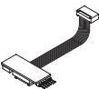
Palmtop programmer connector, Connector programer tool
Connecteurprogrammatisdepoche, StockoverhinderPalmettoProgrammier
Steckverbinder Palmitop-Programmelle Capenader del programmer de bolsole
Conector del programador de bolsinio, Conceptor programarbae pelmatr
Connector programme bare painttop
Optional radio-receiver connector,
Make sure the spring is not under tension and the boom is not fitted.
WARNING! Important safety instructions. Carefully read and comply with the Warnings booklet and Instruction booklet that come with the product as incorrect installation can cause injury to people and animals and damage to property. They contain important information regarding safety, installation, use and maintenance. Keep hold of instructions so that you can attach them to the technical file and keep them handy for future reference.
1) GENERAL SAFETY
WARNING! An incorrect installation or improper use of the product can cause damage to persons, animals or things.
- The "Warnings" leaflet and "Instruction booklet" supplied with this product should be read carefully as they provide important information about safety, installation, use and maintenance.
- Scrap packing materials (plastic, cardboard, polystyrene etc) according to the provisions set out by current standards. Keep nylon or polystyrene bags out of children's reach.
- Keep the instructions together with the technical brochure for future reference.
- This product was exclusively designed and manufactured for the use specified in the present documentation. Any other use not specified in this documentation could damage the product and be dangerous.
- The Company declines all responsibility for any consequences resulting from improper use of the product, or use which is different from that expected and specified in the present documentation.
- Do not install the product in explosive atmosphere.
- Make sure the stated temperature range is compatible with the site in which the automated system is due to be installed.
- The units making up the machine and its installation must meet the requirements of the following European Directives: 2004/108/EEC, 2006/95/EEC, 98/37/EEC, 99/05/EEC (and later amendments). For all countries outside the EEC, it is advisable to comply with the above-mentioned standards, in addition to any national standards in force, to achieve a good level of safety.
- The Company declines all responsibility for any consequences resulting from failure to observe Good Technical Practice when constructing closing structures (door, gates etc.), as well as from any deformation which might occur during use.
- The installation must comply with the provisions set out by the following European Directives: 2004/108/EEC, 2006/95/EEC, 98/37/EEC, 99/05/EEC and subsequent amendments.
- Disconnect the electrical power supply before carrying out any work on the installation. Also disconnect any buffer batteries, if fitted.
- Have the automated system's mains power supply fitted with a switch or omnipolar thermal-magnetic circuit breaker with a contact separation of at least 3.5mm : the device must be connected upline from the power supply terminals.
- Check that a differential switch with a 0.03A threshold is fitted just before the power supply mains.
- Check that earthing is carried out correctly: connect all metal parts for closure (doors, gates etc.) and all system components provided with an earth terminal.
- Keep mains connections well separated from low voltage connections.
- Keep mains connections well separated (at least a 2.5mm air gap) from safety extra low voltage connections.
- During installation, wires must be secured with additional fastening near the terminals or electrical connections, using devices such as cable clamps.
- Use wiring with double-insulated cables (sheathed cables) right up to the immediate vicinity of terminals if safety extra low voltage cables need to be run together with the low voltage supply cable. Similarly, the power cable's sheathing must only be stripped back in the immediate vicinity of the terminal board.
- Specify that the actuator must be lifted by at least two operators or using appropriate equipment.
- Fit all the safety devices (photocells, electric edges etc.) which are needed to protect the area from any danger caused by squashing, conveying and shearing, according to and in compliance with the applicable directives and technical standards.
- Position at least one luminous signal indication device (blinker) where it can be easily seen, and fix a Warning sign to the structure.
- Any fixed controls must be installed within sight of the door but away from moving parts. Unless the control is key operated, it must be installed at a height of at least 1.5m and in a place where it cannot be reached by the public
- Make sure that nothing can be crushed between the guided part and surrounding fixed parts during operation
- Once installation is complete, make sure the motor has the right settings and that the safety and release systems are working properly.
- The Company declines all responsibility with respect to the automation safety and correct operation when other manufacturer's components are used.
-
Only use original parts for any maintenance or repair operation.
-
Do not modify the automation components, unless explicitly authorised by the Company.
- Instruct the product user about the control systems provided and the manual opening operation in case of emergency.
- Do not allow persons or children to remain in the automation operation area.
- Keep radio control or other control devices out of children's reach, in order to avoid unintentional automation activation.
- The user must avoid any attempt to carry out work or repair on the automation system, and always request the assistance of qualified personnel.
- Anything which is not expressly provided for in the present instructions, is not allowed.
Installation must be carried out using the safety devices and controls prescribed by the EN 12978 Standard.
WARNING! For connection to the mains power supply, use a multicore cable with a cross-section of at least 3 × 1.5 ~mm^2 of the kind provided for by the regulations mentioned above (by way of example, if the cable is not protected, it must be rated H07 RN-F or higher, while if it is protected it must be rated at least H05 VV-F with a cross-section of 3 × 1.5 ~mm^2 ). Only use plastic raceways for both safety extra low voltage (SELV) cables and low voltage (230 V) cables.
USE OF AUTOMATION
As automation can be remotely controlled and therefore not within sight, it is essential to frequently check that all safety devices are perfectly efficient.
WARNING! In case of any malfunction in the safety devices, take immediate action and require the assistance of a specialised technician.
It is recommended to keep children at a safe distance from the automation field of action.
CONTROL
The automation system is used to obtain motorised access control. There are different types of control (manual, remote, magnetic badge, mass detector etc.) depending on the installation requirements and characteristics. For the various control systems, see the relevant instructions. Do not use the automated device or put it into operation until the boom has been balanced.
MAINTENANCE
WARNING: before opening the door, the spring must be unloaded (vertical boom). WARNING: Before carrying out any maintenance to the installation, disconnect the mains power supply. The following points need checking and maintenance:
- Photocell optics. Clean occasionally.
- Electric edge. Carry out a periodical manual check to ensure that the edge stops the bar in case of obstacles.
- Dismantle the gearmotor and replace the lubricating grease every two years.
- When any operational malfunction is found, and not resolved, disconnect the mains power supply and request the assistance of a specialised technician (installer). When the operator is out of order, activate the emergency release (see Fig. Y), if necessary, so as to release the manual boom opening and closing operations.
SCRAPPING
Materials must be disposed of in conformity with the current regulations. In case of scrapping, the automation devices do not entail any particular risks or danger. In case of recovered materials, these should be sorted out by type (electrical components, copper, aluminium, plastic etc.).
DISMANTLING
WARNING: before opening the door, the spring must be unloaded (vertical boom). When the automation system is disassembled to be reassembled on another site, proceed as follows:
- Disconnect the power supply and the entire electrical installation.
- Remove the actuator from its fixing base.
- Disassemble all the installation components.
- In the case where some of the components cannot be removed or are damaged, they must be replaced.
Correct controller operation is only ensured when the data contained in the present manual are observed. The Company is not to be held responsible for any damage resulting from failure to observe the installation standards and the instructions contained in the present manual.
The descriptions and illustrations contained in the present manual are not binding. The Company reserves the right to make any alterations deemed appropriate for the technical, manufacturing and commercial improvement of the product, while leaving the essential product features unchanged, at any time and without undertaking to update the present publication.
2) GENERAL INFORMATION
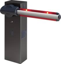
Compact electromechanical barrier suitable for enclosing private areas and car parks and for use across entrances used by vehicle traffic only. Available for entrance/exit points between 3 and 5 metres across. Adjustable electromechanical limit switches ensure the boom stops in the correct position.
The emergency release for manual operation is operated by a lock with a personalized key.
The actuator is always supplied ready for assembly on the left.
Where necessary, the opening direction can always be reversed with a few simple operations. The foundation base mod. CBO (on request) can be supplied to make the barrier easier to install.
Provision for accessories makes installing them straightforward, with no need to drill additional holes.
3) TECHNICAL SPECIFICATIONS
| MOTOR | |
| Power supply: | 230V±10% 50Hz(*) |
| Max. power input: | 300W |
| Capacitor: | 8μF 450V (230V): 32μF 250V (110V) |
| Current demand (with accessories): | 1,4 A: 2.8 A |
| Insulation class: | F |
| Internal lubrication: | lifetime greased |
| Max. torque: | 85 Nm (MOOVI 30) 250 Nm (MOOVI 50) |
| Opening time: | 4s (MOOVI 30) 8s (MOOVI 50) |
| Boom length: | max. 3m (MOOVI 30) max. 5m (MOOVI 50) |
| Impact reaction (Safety Edge): | stop or stop and reverse |
| Mechanical manual release: | personalized key |
| Type of boom: | rectangular |
| Limit switches: | electric, built-in and adjustable |
| Maximum n° of operations in 24hrs: | 1200 (MOOVI 30) 600 (MOOVI 50) |
| Operating temperature range: | da -10°C a +55°C |
| Protection rating: | IP 24 |
| Actuator weight (without boom): | 35,6 Kg |
| Flashing light: | 230V~ 25W max |
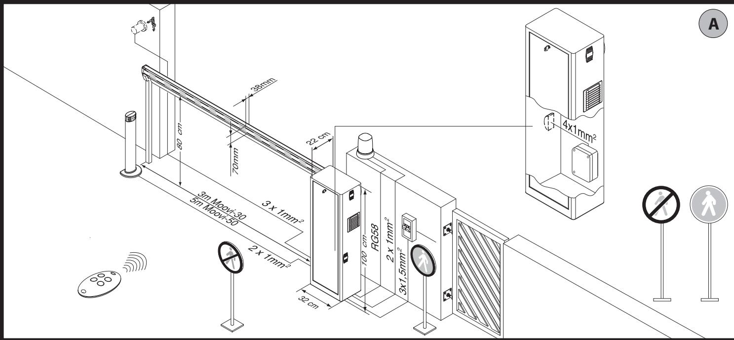
| Dimensions: | see fig.A |
| CONTROL UNIT | |
| Accessories power supply: | 24V-(demand max. 180mA) |
| Fuses: | see figures I, J |
| Max. motor output: | 500 W |
| Work time: | max. 10 sec. |
(^*) = special supply voltages to order
4.1) FOUNDATION PLATE (Fig.B1)
4.2) ANCHOR BOLTS (Fig.B2)
5) ACTUATOR ASSEMBLY
WARNING! The barrier must be used only for entrance/exit points intended for vehicle traffic. Pedestrians must not be allowed to pass within range of the automated system. Make sure there is a separate entrance/exit just for pedestrians.
The entrance/exit must be suitably signposted with the compulsory signs illustrated in Fig.A.
WARNING: before opening the door, the spring must be decompressed (vertical boom). The door in the cabinet must face towards the inside of the property. Standing in the middle of the entrance, facing out, if the cabinet is on your left, the barrier is on your left: if the cabinet is on your right, the barrier is on your right.
The actuator is always supplied ready for assembly on the left.
6) Assembly on left (Fig. A, B, C, D).
It is easier to install the Shearing hazard protection kit MOOVI PRM (optional extra) before the boom is assembled on the automated system.
Balance the boom as illustrated in Fig. AB.
7) Assembly on right (Fig. AA).
Balance the boom as illustrated in Fig. AB.
8) Boom assembly (Fig. D).
9) BOOM BALANCING (Fig. AB).
For Moovi 30:
WARNING! During the closing operation, the balancing spring must never be fully compressed. Fig.AB rif.3 shows the position for determining the minimum size that the compressed spring can be allowed to reach with the boom in the open position (vertical).
10) OPTIONAL ACCESSORIES (Fig.E)
- Foundation base CBO
- Shearing hazard protection kit KIT MOOVI PRM
- Photocell 130 fastening post kit KIT MOOVI 130
- Fixed end rest for boom FAF
- Folding leg to support boom MOOVI GA (MOOVI 50 only)
Cushioned folding leg to support boom MOOVI GAMA - Skirt ready assembled on boom SB
- Safety edge BIR
- Lights kit for booms between 3m and 4.5m long KIT MOOVI LIGHT
- Lights kit for booms 5m or 6m long KIT MOOVI LIGHT 1
- Top or bottom boom covering profile MOOVI PCA
- SS (fig. J) Barrier open light optional board. Works with electric limit switches only.
MOOVI accessories (boom length limits and balancing) (Fig. AF)
For further information on installing and using the accessories, refer to the relevant instruction manual.
11) Assembling the shearing hazard protection kit MOOVI PRM (Fig.AC)
12) Assembling the flashing light RAY X/RAY X SA (FIG.AD)
- Complete assembly and wiring as directed in instructions provided for RAY X/RAY X SA.
13) Assembling Photocell 130 / Moovi 130 (FIG. AE).
14) ADJUSTING THE LIMIT SWITCHES (Fig. G)
WARNING: before opening the door, the spring must be decompressed (vertical boom). Prepare the electrical system (fig. A), referring to the standards in force. Keep mains power connections well separated from service connections (photocells, safety edges, control devices, etc.).
WARNING! For connection to the mains power supply, use a multicore cable with a cross-section of at least 3 × 1.5 ~mm^2 of the kind provided for by the regulations mentioned above (by way of example, if the cable is not protected, it must be rated H07 RN-F or higher, while if it is protected it must be rated at least H05 VV-F with a cross-section of 3 × 1.5 ~mm^2 ).
16) WIRING (FIG. F, I, J)
WARNING: Wiring must be carried out by qualified, expert personnel in a professional manner and in accordance with all regulations in force, using appropriate materials.
| BORNE | DESCRIPTION |
| 1-2 | Power supply 230V +/- 10% 50Hz (Neutral to terminal 1). |
| 3-4-5 | Motor M connection (terminal 4 common, terminals 3-5 motor start and capacitor). |
| 1-4 | 230V flashing light connection |
| 7-8 | START input or key selector (N.O.) with trimmer TW=max. OPEN input (N.O.) with trimmer TW=min. |
| 7-9 | STOP button (N.C.). If not used, leave jumpered. |
| 7-10 | Photocell or pneumatic safety edge input (N.C.). If not used, leave jumpered. |
| 7-11 | Opening limit switch (N.C.). If not used, leave jumpered. |
| 7-12 | Closing limit switch (N.C.). If not used, leave jumpered. |
| 13-14 | 24 V~output to supply photocell and other devices. |
| 15-16 | Output for barrier open light / 2nd radio channel. |
| 17-18 | Antenna receiver input (17 signal 18 braiding). |
| 19-20 | PEDESTRIAN input (N.O.) with trimmer TW=max. CLOSE input (N.O.) with trimmer TW=min. |
| JP4 | 1-2 channel radio-receiver board connector. |
17) ADJUSTMENTS
RECOMMENDED ADJUSTMENT SEQUENCE:
Adjusting the limit switches (Fig. G)
Programming transmitters (Fig. H)
Setting of parameters/logic, where necessary
17.1) LEDs (Fig.J)
ALPHA-ALPHA BOM control panels feature a series of self-diagnosis LEDs via which all functions can be monitored. LED functions are as follows:
| LED | DESCRIPTION |
| DL1 | Built-in radio receiver LED. |
| DL2 | START (trimmer TW=max) - lights when START command given OPEN (trimmer TW=min) - lights when OPEN command given |
| DL3 | STOP - goes off when Stop command given. |
| DL4 | PHOT - goes off when photocells are not aligned or when there is an obstacle. |
| DL5 | SWO - goes off when opening limit switch command given. |
| DL6 | SWC - goes off when closing limit switch command given. |
17.2) DIP SWITCHES (DIP SWITCH TABLE "A") (Fig. J)
| TRIMMER | ADJUSTMENTS | DESCRIPTION |
| TCA | 0 sec. | (Dip1 - TCA set to ON). Adjusts automatic closing time, following which the barrier closes automatically (adjustable in range 0 to 90 sec.). |
| 90 sec. | ||
| TW | min. | Inputs 7-8 and 19-20 are taken respectively to mean OPEN and CLOSE. |
| max. | Inputs 7-8 and 19-20 are taken respectively to mean Start and Pedestrian. |
18) BUILT-IN RECEIVER
Receiver's output channels:
- Output channel 1, if activated, gives the START command.
- Output channel 2, if activated, commands the 2nd radio channel relay to energize for 1 sec..
Usable transmitter versions:
All ROLLING CODE transmitters compatible with

18.1) INSTALLING THE ANTENNA
Use an antenna tuned to 433MHz.
Use RG58 coax cable to connect the Antenna and Receiver.
Metal bodies close to the antenna can interfere with radio reception. If the transmitter's range is limited, move the antenna to a more suitable position.
18.2) PROGRAMMING
Transmitters can be memorized in manual mode, in remote mode (DIP 6 = ON) or by means of the universal handheld programmer, which means installations can be created in "receiver community" mode and the installation's complete database can be managed via the EEdbase software.
18.3) MANUAL PROGRAMMING (Fig.H, AF)
In the case of standard installations in which advanced features are not required, transmitters can be memorized manually.
1) If you want the transmitter's T key to be memorized as the start key, press the SW1 button on the control panel. Alternatively, if you want the transmitter's T key to be memorized as the second radio channel, press the SW2 button on the control panel
2) When LED DL1 flashes, press the transmitter's hidden key P1. LED DL1 will stay steadily lit.
3) Press the key of the transmitter to be memorized, LED DL1 will start flashing again.
4) To memorize another transmitter, repeat steps 2) and 3).
5) To exit memorizing mode, wait for the LED to go off completely.
IMPORTANT NOTE: THE FIRST TRANSMITTER MEMORIZED MUST BE IDENTIFIED BY ATTACHING THE KEY LABEL (master).
In the event of manual programming, the first transmitter assigns the key code to the receiver: this code is required to subsequently clone the radio transmitters.
18.4) REMOTE PROGRAMMING (DIP SW 6=ON).
1) Press the hidden key of a transmitter that has already been memorized in standard mode via manual programming.
2) Press the normal key (T1-T2-T3-T4) of a transmitter that has already been memorized in standard mode via manual programming.
3) LED DL1 flashes. Press within 10 sec. the hidden key of a transmitter to be memorized.
4) LEDDL1 is steadily lit. Press the normal key (T1-T2-T3-T4) of a transmitter to be memorized.
The receiver exits programming mode after 10 sec.: you can use this time to enter other new transmitters.
This mode does not require access to the control panel.
18.5) ERASING THE CONTROL PANEL'S MEMORY (Fig.AF)
To erase the control panel's memory completely, hold down the SW1 and SW2 buttons on the control panel at the same time for 10 seconds (LEDDL1 flashes). When LED DL1 is steadily lit it means the memory has been erased correctly. To exit memorizing mode, wait for the LED to go off completely.
19) EMERGENCY RELEASE (Fig. Y)
WARNING: When needing to activate the release in an actuator without a boom, make sure the balancing spring is not compressed (boom in opening position).
20.1) Boom fails to open. Motor not running.
WARNING: before opening the door, the spring must be decompressed (vertical boom).
1) Make sure the photocells are not dirty, misaligned or have had their beam broken.
2) Check that the motor is connected properly.
3) Make sure power is being supplied correctly to electronic equipment. Check for blown fuses. If a fuse is malfunctioning, remove and replace as illustrated in Fig. I, J.
4) If the panel is not working, replace it.
5) Grease the spring guide tie rods if you encounter noise or vibrations.
20.2) Boom fails to open. Motor running but there is no movement.
1) Manual release is still engaged. Reset to motorized operation.
2) If the release is in the motorized operation position, check the gearbox for damage.
17.2) TABLE A: DIP SWITCH
| DIP | Default | Definition | Cross out setting used | Description |
| DIP 1 | ON | TCA-Automatic closing time. | ON | Automatic closing ON. |
| OFF | Automatic closing OFF. | |||
| DIP 2 | ON | FCH- Photocells. | ON | Photocells active during closing only. |
| OFF | Photocells active during closing and opening. | |||
| DIP 3 | OFF | BLI - Block Pulses. | ON | START commands not accepted during opening. |
| OFF | START commands accepted during opening. | |||
| DIP 4 | OFF | 3P/4P - 3 steps or 4 steps. | ON | Switches to 3-step logic. |
| OFF | Switches to 4-step logic. | |||
| DIP 5 | OFF | CODE FIX - Fixed code. | ON | Activates built-in receiver in fixed-code mode. |
| OFF | Activates built-in receiver in rolling-code mode. | |||
| DIP 6 | OFF | RADIO LEARN - Transmitter programming. | ON | Enables wireless memorizing of transmitters (Sect. "Remote Programming"). |
| OFF | Disables wireless memorizing of transmitters. Transmitters are memorized only by means of manual programming. | |||
| DIP 7 | OFF | SCA-Gate open light or 2nd radio channel. | ON | Activates relay output as 2nd radio channel. |
| OFF | Activates relay output in Gate open light mode. | |||
| DIP 8 | OFF | FAST CLOSE | ON | Closes barrier after the photocells are cleared before waiting for the set TCA to elapse. |
| OFF | Command not enabled. |
MANUEL D'INSTALLATION
17.2) TABLEAU A: COMMUTATEUR DIP
17.2) TABLA "A" DIP SWITCH
10) OPTIONE ACCESSORIES (Fig.E)
Thank you for choosing this product. The Firm is confident that its performance will meet your operating needs. This product meets recognized technical standards and complies with safety provisions. We hereby confirm that it is in conformity with the following European directives: 2004/108/EEC, 2006/95/EEC, 98/37/EEC, 99/05/EEC (and later amendments).
1) GENERAL SAFETY
WARNING Important safety instructions. Carefully read and comply with the warnings booklet and Instruction booklet that come with the product as improper use can cause injury to people and animals and damage to property. Keep hold of instructions for future reference. This product has been designed and built solely for the purpose indicated herein. Uses not contemplated herein might result in the product being damaged and could be a source of danger.
- The Firm disclaims all responsibility resulting from improper use or any use other than that for which the product has been designed, as indicated herein, as well as for failure to apply Good Practice in the construction of entry systems (doors, gates, etc.) and for deformation that could occur during use.
If installed and used correctly, the automated system will meet the required level of safety. Nonetheless, it is advisable to observe certain rules of behaviour so that accidental problems can be avoided: - Keep adults, children and property out of range of the automated system, especially while it is operating.
- This application is not meant for use by people (including children) with impaired mental, physical or sensory capacities, or people who do not have suitable knowledge, unless they are supervised or have been instructed by people who are responsible for their safety.
- Children must be supervised to ensure they do not play with the application. Keep remote controls or other control devices out of reach of children in order to avoid the automated system being operated inadvertently.
- The manual release's activation could result in uncontrolled boom movements if there are mechanical faults or loss of balance.
- Do not deliberately hinder the boom's movement and do not attempt to open the barrier manually unless the actuator has been released with the relevant release knob.
- Check the system frequently, especially the bracket, springs and supports, to detect any loss of balance and signs of wear or damage.
- When cleaning the outside or performing other maintenance work, always cut off mains power.
- Keep the photocells' optics and illuminating indicator devices clean. Check that no
branches or shrubs interfere with the safety devices (photocells).
- Do not use the automated system if it is in need of repair. In the event of a malfunction, cut off the power, activate the emergency release to allow access and call in qualified technical personnel (professional installer).
- If the automated system requires work of any kind, employ the services of qualified personnel (professional installer). All wiring that involves opening the cover must be carried out by qualified personnel. The user cannot open said cover.
- Have the automated system checked by qualified personnel once a year.
- Anything that is not explicitly provided for in these instructions is not allowed.
- The operator's proper operation can only be guaranteed if the information given herein is complied with. The Firm shall not be answerable for damage caused by failure to comply with the installation rules and instructions featured herein.
- Descriptions and illustrations herein are not binding. While we will not alter the product's essential features, the Firm reserves the right, at any time, to make those changes deemed opportune to improve the product from a technical, design or commercial point of view, and will not be required to update this publication accordingly.
MANUALE D'USO (F)
BFT Automation UK Ltd
Unit 8E, Newby Road
Industrial Estate Hazel Grove, Stockport,
Cheshire, SK7 5DA - UK
tel.+44 (0) 161 4560456 - fax +44 (0) 161 4569090
e-mail: info@bftautomation.co.uk
BET BENELUX SA
Parc Industriel 1.Rue du commerce 12
1400 Nivelles - Belgium
tel. +32 (0)67 55 02 00 - fax +32 (0)67 55 02 01
e-mail: info@bftbenelux.be
BFT-ADRIA d.o.o.
Obrovac 39
51218 Dražice (Rijeka)
Hrvatska-Croatia
tel.+385(0)51502640-fax+385(0)51502644
e-mail:info@bft.hr
BFT Polska Sp.z o.o.
ul.Koafcinska 35
03-171 Warszawa - Poland
tel.+48228141222-fax +48 228143918
e-mail: biuro@bft.com.pl
BFT USA BFT U.S., Inc.
6100 Broken Sound Pkwy.N.W., Suite 14
Boca Raton,FL 33487-U.S.A
T: +1 561.995.8155 - F: +1 561.995.8160
TOLL FREE 1,877,995,8155 - info.bft@bft-usa.com
3020-305 COIMBRA - PORTUGAL
tel.+351239082790-fax+351239082799
e-mail: geral@bftportugal.com