
LIVE-5G - Surveillance Camera AIRLIVE - Free user manual and instructions
Find the device manual for free LIVE-5G AIRLIVE in PDF.
| Brand | AIRLIVE |
| Model | LIVE-5G |
| Product type | Surveillance camera |
| Power supply | DC 5V 1A |
| Dimensions (estimated) | 10 x 6 x 6 cm |
| Weight (estimated) | 200 g |
| Video resolution | 1080p Full HD |
| Night vision | Yes, up to 10 meters |
| View angle | 90° |
| Connectivity | Wi-Fi 5 GHz, Ethernet |
| Motion detection | Yes |
| Two-way audio | Yes |
| Storage | MicroSD card up to 128 GB, cloud |
| Mobile app | Yes, compatible with iOS and Android |
| Installation | Indoor/outdoor, wall mount included |
| Protection rating | IP65 (weather-resistant) |
| Maintenance | Clean with a soft, dry cloth |
| Safety | Use the provided adapter, avoid moisture |
| Spare parts | Power adapter, Ethernet cable, mount |
| Warranty | 2 years |
Frequently Asked Questions - LIVE-5G AIRLIVE
User questions about LIVE-5G AIRLIVE
0 question about this device. Answer the ones you know or ask your own.
Ask a new question about this device
Download the instructions for your Surveillance Camera in PDF format for free! Find your manual LIVE-5G - AIRLIVE and take your electronic device back in hand. On this page are published all the documents necessary for the use of your device. LIVE-5G by AIRLIVE.
USER MANUAL LIVE-5G AIRLIVE
Powered by OvisLink Corp.
www.airlive.com
Live-5G
5-Port Gigabit Ethernet Switch
Quick Setup Guide
Declaration of Conformity
We, Manufacturer/Importer
OvisLink Corp.
5F., NO.6, Lane 130, Min-Chuan Rd., Hsin-Tien City, Taipei County, Taiwan
Declare that the product
5-Port Gigabit Ethernet Switch
AirLive Live-5G
is in conformity with
In accordance with 89/336 EEC-EMC Directive and 1999/5 EC-R & TTE Directive
Clause
EN 55022:2006 Class A
Limits and methods of measurement of radio disturbance characteristics of information technology equipment
EN 61000-3-2:2000+A2:2005
Disturbances in supply systems caused by household appliances and similar electrical equipment "Harmonics"
EN 61000-3-3:1995+A1:2001+A2:2005
Disturbances in supply systems caused by household appliances and similar electrical equipment "Voltage fluctuations"
■ AS/NZSCISPR22:2006, Class A
Electromagnetic compatibility requirements for radio disturbance characteristics of information technology equipment.
EN 60950-1:2006
Safety for information technology equipment including electrical business equipment
CE marking
Manufacturer/Importer
Position/ Title : Vice President
Date:2008/9/1
Input Power: DC 5V 1A
Note: Use the power adapter packed with the device. Incorrect power input can cause device damage.
LED Rules:
| LED Indicator | Color | Status | Meaning |
| Power | ● Green | ON OFF | Power ON Power OFF |
| Link/Act | ● Green | ON Blinking OFF | Port is connected Transmitting/Receiving Port is not connected |
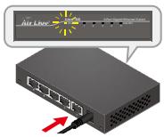
Installation Steps
- Remove the switch and accessories from the package.
- Connect power to the switch. Make sure that "Power" LED is on.
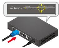
- Connect devices to the switch, and check whether the "Link/Act" light is on. If not, please make sure that power is on for the other device or PC.
Important Notice:
- The maximum cabling distance is 100 meters.
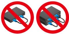
- Do not create a network loop.
- Always check the LED lights for troubleshooting.
Vstrupi napajeni: DC 5V 1A
BxOHaMoUHocTb:DC5V1A
PIMcHAnHe: NcONb3yTe 6Nok NtAHnA, HaxOdaunCBA KOMNJIeKTe C yCTPOCTBOM. BcOKn NtAHnA O T CTOpOHNX Pnno3BOHTeJIeM MOrT bYbEcnT yCTPOCTB0 n3 CTPOs.
NapametpbI INdkaunn:
Brand : AIRLIVE
Model : LIVE-5G
Category : Surveillance Camera