
AV3850SU - To scan AVISION - Free user manual and instructions
Find the device manual for free AV3850SU AVISION in PDF.
User questions about AV3850SU AVISION
0 question about this device. Answer the ones you know or ask your own.
Ask a new question about this device
Download the instructions for your To scan in PDF format for free! Find your manual AV3850SU - AVISION and take your electronic device back in hand. On this page are published all the documents necessary for the use of your device. AV3850SU by AVISION.
USER MANUAL AV3850SU AVISION
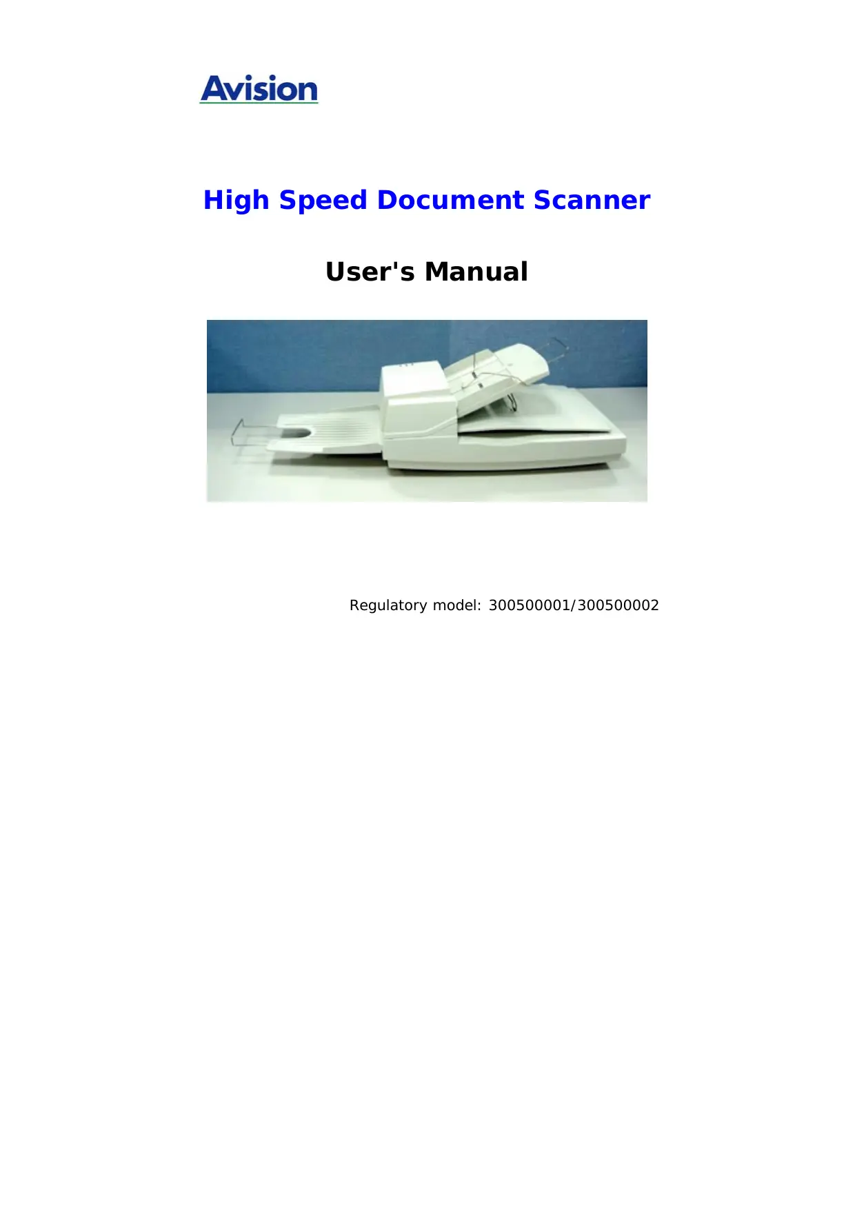
High Speed Document Scanner
User's Manual
Regulatory model: 300500001/300500002
Trademarks
Microsoft is a U.S. registered trademark of Microsoft
Corporation.
Windows and MS-DOS are trademarks of Microsoft Corporation.
IBM, PC, AT, XT are registered trademarks of International
Business Machines Corp.
ENERGY STAR® is a U.S. registered mark.
Other brands and product names herein are trademarks or
registered trademarks of their respective holders.
Copyright
All rights reserved. No part of this publication may be reproduced, transmitted, transcribed, stored in a retrieval system, or translated into any language or computer language, in any form or by any means, electronic, mechanical, magnetic, optical, chemical, manual, or otherwise, without the prior written permission of Avision Inc.
Material scanned by this product may be protected by governmental laws and other regulations, such as copyright laws, the customer is solely responsible for complying with all such laws and regulations.
Warranty
The information contained in this document is subject to change without notice.
Avision makes no warranty of any kind with regard to this material, including, but not limited to, the implied warranties of fitness for a particular purpose.
Avision shall not be liable for errors contained herein or for incidental or consequential damages in connection with the furnishing, performance, or use of this material.
FCC Radio Frequency Interference Statement
This product has been tested and found to comply with the limits for a class B digital device, pursuant to Part 15 of the FCC rules. Operation is subject to the following two conditions: (1) this device may not cause harmful interference, and (2) this device must accept any interference received, including interference that may cause undesired operation. The FCC Class B limits are designed to provide reasonable protection against harmful interference in a residential installation. This equipment generates, uses, and can radiate radio frequency energy and, if not installed and used in accordance with the instructions, may cause harmful interference to radio communications. However, there is no guarantee that interference will not occur in a particular installation. If this equipment does cause harmful interference to radio or television reception, which can be determined by turning the equipment off and on, the user is encouraged to try to correct the interference by one or more of the following measures:
Reorient or relocate the receiving antenna.
- Increase the separation between the equipment and receiver.
- Connect the equipment into an outlet on a circuit different from that to which the receiver is connected.
- Consult your point of purchase or service representative for additional suggestions.
CE Warning
This product satisfies the Class B limits of EN55022, EN55024 and safety requirements of EN 60950.
Disposal of Waste Equipment by Users in Private Union

This symbol on the product or on its packaging indicates that the product can not be disposed of with your other household waste. Instead it should be sent to appropriate facilities for recovery and recycling in an effort to protect human health and the environment. Fore more information about where you can drop off your waste equipment for recycling, please contact your local city office, your household waste disposal service or the shop where you purchased the product.

ENERGY STAR
As an ENERGY STAR® Partner, Avision Inc. has found that this product meets the ENERGY STAR® for energy efficiency.
Table of Contents
-
Introduction 1-1
-
Installation 2-1
2.1 Unlocking the Shipping switch 2-1
2.1.1 unlocking the scanner 2-2
2.1.2 locking the Shipping switch 2-3
2.2 SCSI ID 2-4
2.3 USB Interface 2-6
2.4 ADF Paper Chute 2-6
2.5 ADF Output Tray 2-7
2.6 Document Loading 2-8
2.7 ADF Scanning 2-9
2.8 Connecting the Cable 2-10
- Requirements & software installation 3-1
3.1 Scanner Driver Installation 3-1
3.2 Verifying Your Scanner Installation 3-3
3.1.1 A Glance of the Scanner Properties Dialog Box 3-7
- Using the Scanner Properties Dialog Box.... 4-1
4.1 Buttons on the Scanner Properties Dialog Box .. 4-2
4.2 The Image Tab 4-4
4.2.1 The Image Selection Box 4-5
4.2.2 Other Image Options 4-7
4.2.3 Scanning color images.. 4-13
4.2.4 Scanning grayscale images 4-14
4.2.5 Scanning B&W images. 4-14
4.2.6 Editing Profiles. 4-15
4.3 The Compression Tab 4-18
4.4 The Color Dropout Tab 4-20
4.4.1 Color Dropout Selection 4-20
4.4.2 Other Color Dropout Options.. 4-21
4.5 The Paper Tab 4-23
4.5.1 Cropping 4-24
4.5.2 Other Paper Selection 4-27
4.5.3 Relative to Document 4-32
4.6 The Preview Tab 4-35
4.7 The Options Tab. 4-36
4.8 The Setting Tab 4-41
4.9 The Information Tab 4-44
-
ISIS Interface Operation 5-1
-
Maintenance 6-1
6.1 Cleaning the ADF 6-1
6.2 Cleaning the Glass.. 6-3
6.3 Replacing the ADF snap-in pad module.... 6-4
6.4 Replacing the ADF Paper Feed Roller 6-6
- Trouble shooting 7-1
7.1 Question and Answer 7-1
7.2 Paper Jam in the ADF 7-5
- Technical Service 8-1
- Specifications 9-1
1. Introduction
Congratulations on your purchase of the document scanner.
Before you install and operate the scanner, please take a few minutes to read through this manual. It provides you with the proper instructions on how to unpack, install, operate and maintain the scanner.
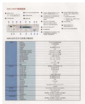
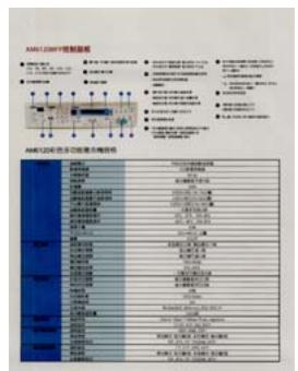
Figure 1-1 shows how the scanner is packed. You can check all items against your "checklist", included with your scanner.
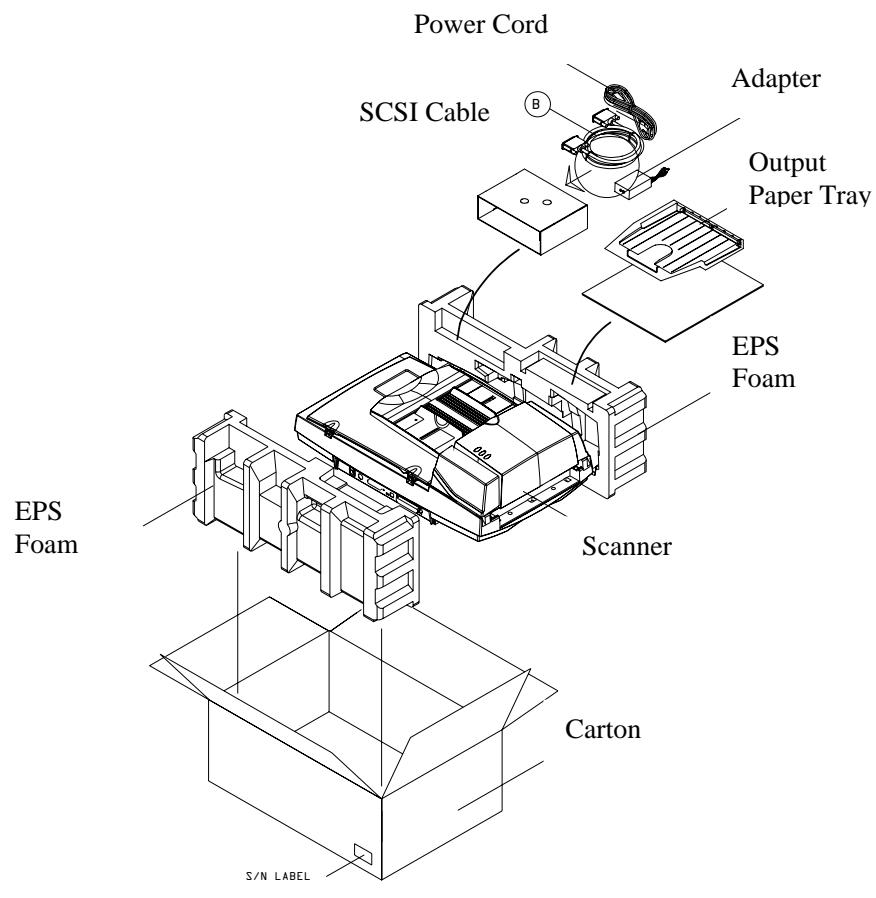
Figure 1-1 Scanner Packing
2. Installation
Please unpack the scanner carefully, and check the contents against the checklist. If any items are missing or damaged, please contact your authorized local dealer immediately.
Precautions
- Keep the scanner out of direct sunlight. Direct exposure to the sun or excessive heat may cause damage to the unit.
- Do not install the scanner in a humid or dusty place.
- Use only the AC adapter (HEG42-240200-7L by Hitron) included with the machine. Using other AC adapters may damage the machine and void the warranty.
- Place the scanner securely on an even, flat surface. Tilted or uneven surfaces may cause mechanical or paper-feeding problems.
- Retain the scanner box and packing materials for shipping purposes.
2.1 Unlocking the Shipping switch
The scanner has a shipping switch that locks the carrier mechanism for transportation purposes. This switch must be unlocked before using the scanner.
Before proceeding, turn the power off, disconnect all cables and follow the instructions below to unlock the shipping switch.
2.1.1 unlocking the scanner
i). Carefully place the scanner in an upright position on its front.
ii). Unlock the scanner by moving the lock switch beneath the scanner to the "Unlock" position (See Figure 2-1).
iii).Gently place the scanner back to its normal position.
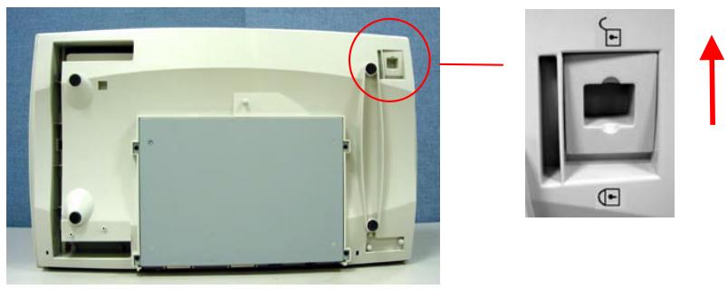
Figure 2-1 Unlocking the Shipping Switch
2.1.2 Locking the Shipping switch
Whenever you need to move the scanner to a new location it is advisable to lock the shipping switch to avoid causing damage to the scanners' internal mechanism. Please follow the instructions below to lock the shipping switch.
1). Turn off the scanner.
2). Lift the Document cover to reveal the flatbed glass and scanning unit.
3). Turn on the scanner.
4). Turn off the scanner again while the scanning unit moved to the end for a few seconds.
5). Place your scanner in an upright position on its front side.
6). Lock your scanner by moving the lock switch to the "Locked position".
7). Place the scanner back to its normal position.
2.2 SCSI ID
When you have several devices on a SCSI chain, you may need to adjust the SCSI ID selector setting located on the back of the scanner. This setting assigns a specific "device ID" to the scanner. If the assignment conflicts with an existing SCSI device, please select a new ID. (See Figure 2-2)
Note: The factory setting for scanner is ID 6. Usually, ID 0 is assigned to an internal hard disk drive, and ID 7, ID 8, and ID 9 are not in actual use.
Using a suitable tool, turn the selector switch until the arrow points to the desired ID number.
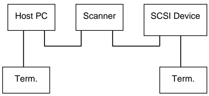
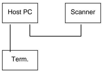
2.3 Setting SCSI Terminator
The scanner is equipped with a built-in terminator switch on the rear of the scanner. (See Figure 2-2). The scanner is equipped with a built-in terminator switch on the rear of the scanner. Turn the terminator switch on if the scanner is to be connected to the computer as the only or the last SCSI device. Turn the terminator switch off if the scanner is to be located between the computer and the other SCSI device.
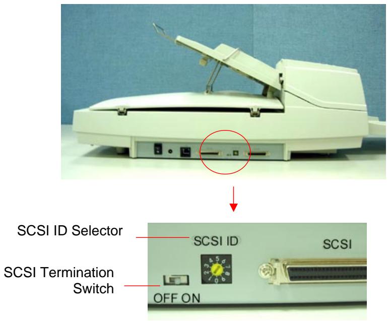
Figure 2-2 Adjusting the SCSI ID setting
2.3 USB Interface
Note that the machine is designed with two ports, SCSI and USB, to connect with the computer. If you are using the USB port, be sure to install the scanner driver before connecting the USB cable to your computer. Otherwise, the scanner may not work properly.
2.4 ADF Paper Chute
i). Lift the paper chute to about 45 degrees.
ii). Pull the paper-chute wire leg down to the grips on the document cover.
iii). Slightly press the paper chute to snap the wire leg into the grips on the document cover.
iv). Pull out the paper chute extension to the length you want.
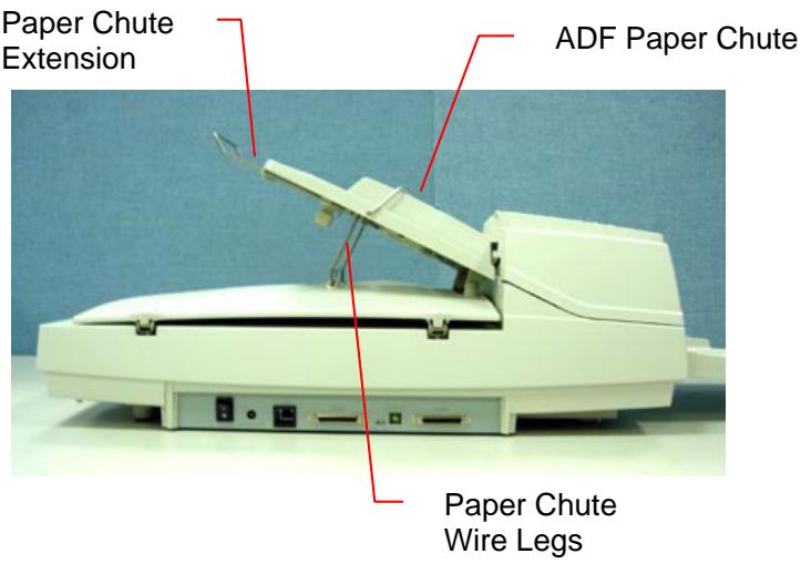
Figure 2-3 Setting the ADF
2.5 ADF Output Tray
i). Hold the output paper tray some 30 degrees aslant as shown in Figure 2-4.
ii). Insert the three protrusions on the output paper tray to the three slots on the ADF.
iii). Release the paper tray gently. Make sure the tray is firmly attached to the ADF.
iv). Pull out the output paper tray extension wire to the desired length.
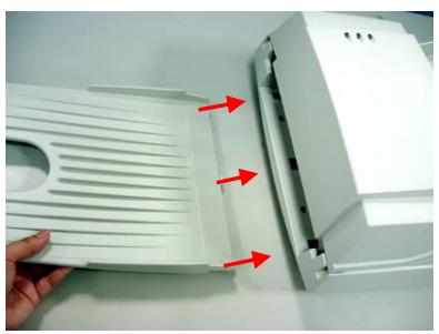
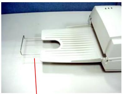
Output Tray Extension Wire
Figure 2-4 Install the ADF Output Paper Tray
2.6 Document Loading
For flatbed scanning
Documents that can not be scanned using the ADF can be placed on the flatbed for scanning. (See Figure 2-5)
i). Place the document to be scanned onto the document glass face down.
ii). Position the document so that the upper-right corner is aligned with the reference mark.
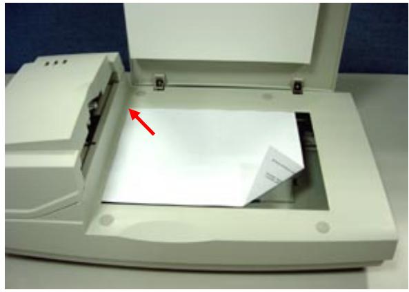
Figure 2-5 Place Document on the scanner
2.7 ADF Scanning
Multiple documents can be fed automatically using the ADF. Refer to Figure 2-6.
i). To prevent occasional paper jam when automatically feeding multiple documents, fan the paper before loading.
ii). Lift the balance wire.
iii). Place the documents onto the ADF paper chute in either paper side (face-down, face-up), with the leading edge in the auto feeder entrance.
Let the balance wire rest on the top of the documents.
iv). Adjust the left and right guides so that they are snug against the sides of the documents.
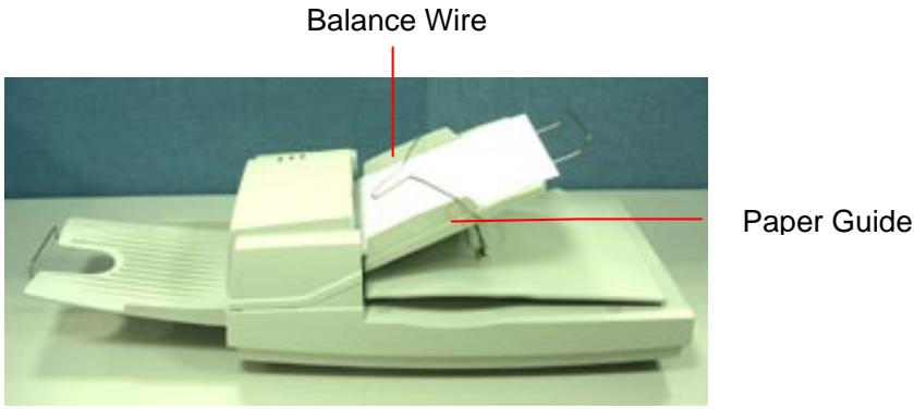
Figure 2-6 Loading Multiple Document
2.8 Connecting the Cable
i). Turning the Power Off
Depress the side marked "O" to turn the power off.
Connect the power cable and SCSI signal cable as shown in Figure 2-7.
ii). Turning the Power On
Depress the side marked "I" to turn the power on. The POWER LED will light. If not, please check the power source.
iii). SCSI Termination/USB Port
The scanner is designed with both the USB and SCSI port. If you wish to connect the scanner with a USB port, please install the scanner driver first and then connect the USB cable. If you wish to connect the scanner with SCSI port, please note the following:
The scanner comes complete with a built in SCSI terminator. If the scanner is the last device in a SCSI chain, the terminator should be switched on. If the scanner is not the last device, the terminator should be off. The terminator on/off switch is located on the back of the scanner, to the left of the SCSI cable connectors.
(Terminator Off)
(Terminator On)
Figure 2-2 Terminator ON/OFF
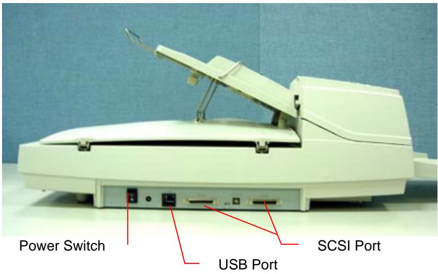
Figure 2-7 Cable Connection
3. Requirements & software installation
To run the scanner at rated speed recommended, you must have the following minimum requirements:
IBM compatible PC 586, Pentium or higher
- Microsoft Windows 95 /NT/98/98SE/Me/2000/XP
One SCSI card installed on your computer; or a USB port on your computer
100M bytes of available hard disk space for installation;
128M bytes of RAM
- A CD-ROM drive.
3.1 Scanner Driver Installation
Important!
If you wish to connect the scanner with a USB port, please install the scanner driver first and then connect the USB cable.
- Start your PC and Windows application.
- Insert the scanner bundled CD to your CD-ROM drive.
- The software installation graphic should appear as below:

If not, press the Start button, choose RUN, and type d:\driver\twain driver (or ISIS driver)\setup.exe (d means the letter indicating your current CD-ROM drive). Click on the OK button.
- Follow the subsequent instructions on the screen to complete the driver and application installation.
3.2 Verifying Your Scanner Installation
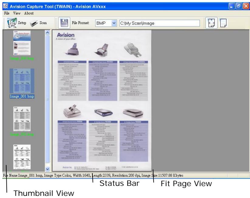
To verify if your scanner installation is correct, Avision provides you a useful test program called Avision Capture Tool. With this tool, you can perform simple scans and view the captured images. In addition, it helps you complete your scan at a rated speed.
The following procedure describes how to verify your scanner installation. If the installation is not correct, please review the preceding section to check if the cable connection and scanner driver have been successfully installed.
Before you begin, be sure the scanner is on.
- Select Start>Programs>Avision AVxxx Scanner>Avision Capture Tool.
The Select Scanner Model dialog box will be displayed.
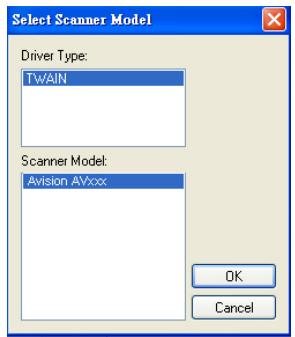
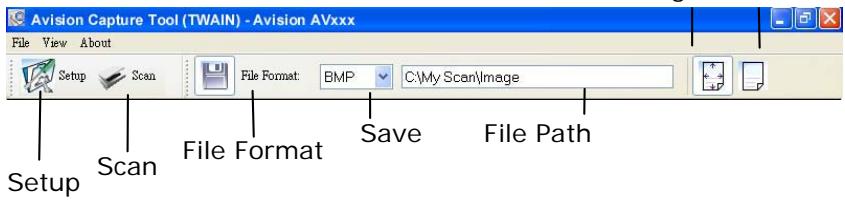
- Select your driver type and scanner model and click OK. The following Avision Capture Tool dialog box will be displayed.
Fit Actual Page Size
- Choose your desired file format from the File Format drop down list box. (Default is BMP, other choice includes TIFF, GIF, and JPEG.)
- Type your desired folder name and file name in the File Path box. (Default is C:\My Scan\Image.)
Note: If you do not wish to save the scanned image, deselect the Save button since default is Save Enable. In this case, the thumbnail view will be disabled. And therefore, after viewing all the scanned images, only the last one will remain on the screen.
- Click the Setup button (Setup) or choose Setup from the File menu to prompt the Scanner Properties dialog box.
Image Selection Box
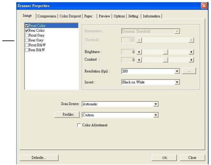
- From the Image Selection Box, choose your desired image type for your scanned image. (Default is Front B&W) If you have a duplex scanner, choose Front and Rear to scan both sides of your document.
- Click OK to quit the Scanner Properties dialog box. (To learn more details about the Scanner Properties dialog box, please see the subsequent chapter, Using the Scanner Properties Dialog Box.)
- Place your document face down on the document glass or face up in the auto document feeder.
- In the Scan Validation dialog box, click the Scan button

or choose Scan from the File menu.
- The document will be scanned and displayed in the Scan Validation screen. After the scanned images have been displayed, your scanner installation verification is completed.
- You can view the scanned image in Fit Page ( ) or Actual Size (100%) button ( ) from the Viewing toolbars at the right side.
- Click the Close box or Quit from the File menu to exit the Scan Validation Tool.
3.1.1 A Glance of the Scanner Properties Dialog Box
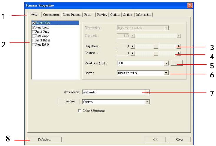
| 1. Tab Options | Choice: Image, Compression, Color Dropout, Paper, Options, Settings, Information. |
| 2. Image Selection Box | Choose your image type and the side of document you wish to scan. Options vary based on type of scanner. |
| 3. Brightness: | Adjust the brightness level from -100 to +100. |
| 4. Contrast | Adjust the contrast level from -100 to +100. |
| 5. Resolution | Determine the quality of the scanned image. The industry standard is 200 dpi. |
| 6. Invert | Reverse the color of your scanned image. |
| 7. Scan Source | Choice: Auto Document Feeder, Flatbed, Flatbed (Book), Automatic (varies due to different scanner model) |
| 8. Defaults | Reset all values on the tabs to the factory default settings. |
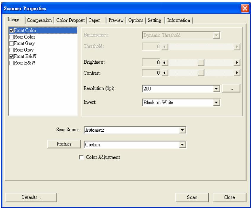
4. Using the Scanner Properties Dialog Box
The Scanner Properties dialog box allows you to configure the scanner's settings. It consists of several tabbed windows each of which will be described in this chapter.
The Scanner Properties dialog box
4.1 Buttons on the Scanner Properties Dialog Box
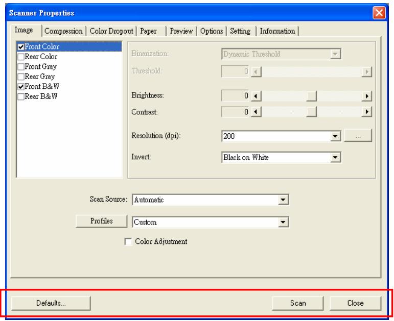
The buttons on the Scanner Properties dialog box
| Buttons | Description |
| Defaults | Click the Defaults button, the factory default settings will be shown on each tab. |
| Scan | After all the scan settings are satisfactory, click the Scan button to start scanning your document. |
| Close | Click the Close button to leave the Scanner Properties dialog box. |
The following table shows the default settings :
| Tab name | Default settings |
| Image | Image : Front B&W Binarization : Dynamic Threshold Resolution : 200 dpi Invert : Blank on White Scan Source : Auto Document Feeder Threshold : None Brightness : None Contrast : None |
| Compression | None |
| Color Dropout | None |
| Paper | Cropping : Automatic Deskew : Yes Orientation : Portrait OverScan : 0.00 Multifeed Detection : None Unit : Inch |
| Options | Rotation Degrees : None Blank Page Removal : None Edge Fill : White , 0 mm Image Control Option : None |
| Setting | Enable Energy Saver : Enable, 15 minutes after last scan action Show Scanning Progress : Yes Show Warning Message : Yes Save Settings after Closing : Yes |
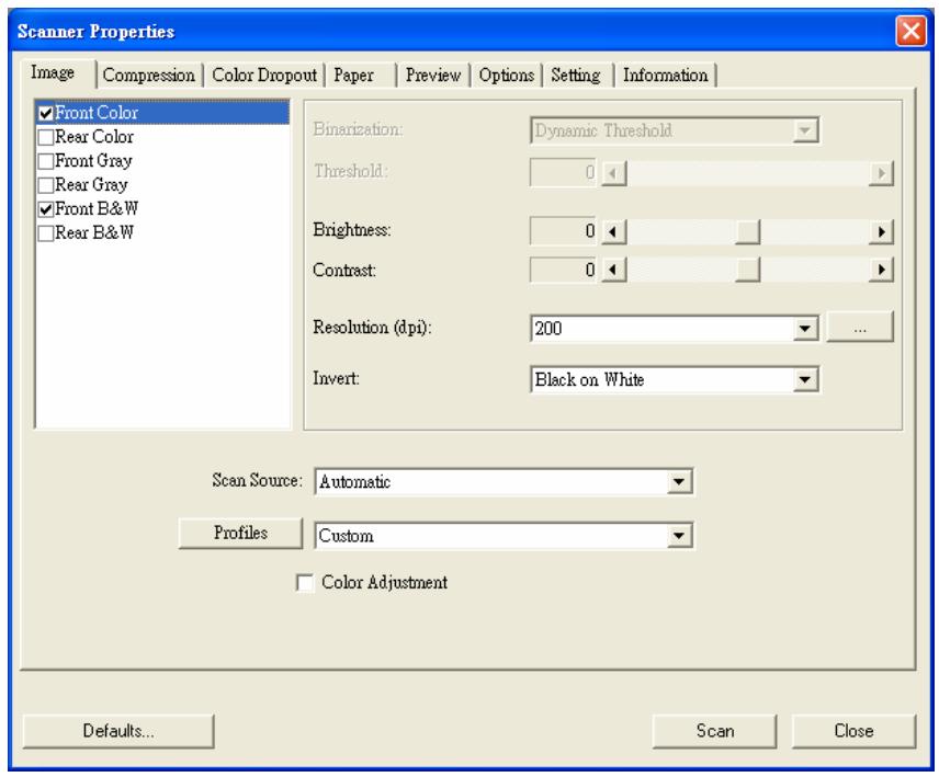
4.2 The Image Tab
The Image tab allows you to choose the front side and (or) the rear side of your document, the type of image, and to set several basic scan settings. Note that except for the resolution, you can set individual scan settings for the front side and the rear side. For example, all settings in the Image tab, Compression tab, Color Dropout tab can be set individually for the front and the rear side. However, the settings in the Paper tab, the Option tab, and the Setting tab have to be set the same for the front and rear side.
The Image tab dialog box
4.2.1 The Image Selection Box
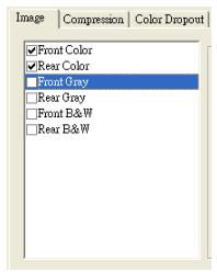
The Image Selection box includes the image type and document side option. If you wish to scan both the front side and the rear side of your color document, you can check both Front Color and Rear Color at the same time. Note the options vary based on type of scanner.
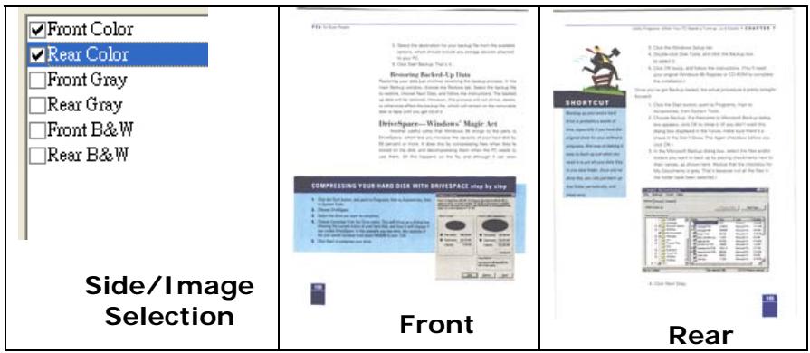
Example 1: Scanning a two-sided color document, both sides in color
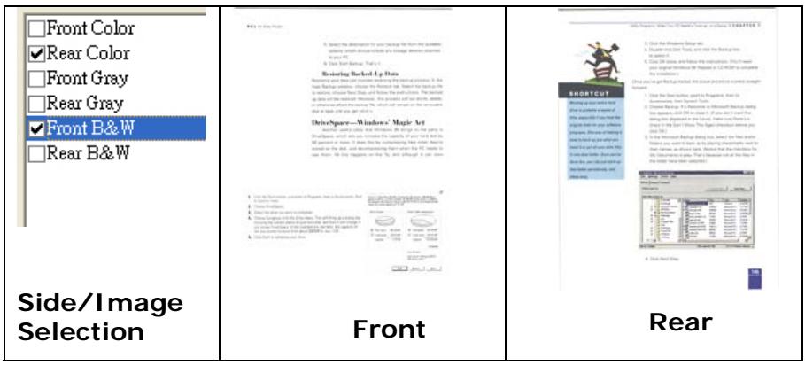
Example 2 : Scanning a two-sided color document, one in B&W(Drop Blue Color : Threshold : 10, Background : 79), the other in color
| Image Type | Description |
| Color | Choose Color if you wish to scan a color image for your original in color. |
| Gray | Choose Gray image if your original contains actual shades of gray. |
| B&W | Choose B&W if your original contains only text pencil or ink sketch. |
| Questions 1. What is the difference between the following statements? 2. How do you interpret these statements? 3. Do you think they are different? 4. What is the difference between the following statements? 5. What is the difference between the following statements? 6. What is the difference between the following statements? 7. What is the difference between the following statements? 8. What is the difference between the following statements? 9. What is the difference between the following statements? 10. What is the difference between the following statements? 11. What is the difference between the following statements? 12. What is the difference between the following statements? 13. What is the difference between the following statements? 14. What is the difference between the following statements? 15. What is the difference between the following statements? 16. What is the difference between the following statements? 17. What is the difference between the following statements? 18. What is the difference between the following statements? 19. What is the difference between the following statements? 20. What is the difference between the following statements? 21. What is the difference between the following statements? 22. What is the difference between the following statements? 23. What is the difference between the following statements? 24. What is the difference between the following statements? 25. What is the difference between the following statements? 26. What is the difference between the following statements? 27. What is the difference between the following statements? 28. What is the difference between the following statements? 29. What is the difference between the following statements? 30. What is the difference between the following statements? 31. What is the difference between the following statements? 32. What is the difference between the following statements? 33. What is the difference between the following statements? 34. What is the difference between the following statements? 35. What is the difference between the following statements? 36. What is the difference between the following statements? 37. What is the difference between the following statements? 38. What is the difference between the following statements? 39. What is the difference between the following statements? 40. What is the difference between the following statements? 41. What is the difference between the following statements? 42. What is the difference between the following statements? 43. What is the difference between the following statements? 44. What is the difference between the following statements? 45. What is the difference between the following statements? 46. What is the difference between the following statements? 47. What is the difference between the following statements? 48. What is the difference between the following statements? 49. What is the difference between the following statements? 50. What is the difference between the following statements? 51. What is the difference between the following statements? 52. What is the difference between the following statements? 53. What is the difference between the following statements? 54. What is the difference between the following statements? 55. What is the difference between the following statements? 56. What is the difference between the following statements? 57. What is the difference between the following statements? 58. What is the difference between the following statements? 59. What is the difference between the following statements? 60. What is the difference between the following statements? 61. What is the difference between the following statements? 62. What is the difference between the following statements? 63. What is the difference between the following statements? 64. What is the difference between the following statements? 65. What is the difference between the following statements? 66. What is the difference between the following statements? 67. What is the difference between the following statements? 68. What is the difference between the following statements? 69. What is the difference between the following statements? 70. What is the difference between the following statements? 71. What is the difference between the following statements? 72. What is the difference between the following statements? 73. What is the difference between the following statements? 74. What is the difference between the following statements? 75. What is the difference between the following statements? 76. What is the difference between the following statements? 77. What is the difference between the following statements? 78. What is the difference between the following statements? 79. What is the difference between the following statements? 80. What is the difference between the following statements? 81. What is the difference between the following statements? 82. What is the difference between the following statements? 83. What is the difference between the following statements? 84. What is the difference between the following statements? 85. What is the difference between the following statements? 86. What is the difference between the following statements? 87. What is the difference between the following statements? 88. What is the difference between the following statements? 89. What is the difference between the following statements? 90. What is the difference between the following statements? 91. What is the difference between the following statements? 92. What is the difference between the following statements? 93. What is the difference between the following statements? 94. What is the difference between the following statements? 95. What is the difference between the following statements? 96. What is the difference between the following statements? 97. What is the difference between the following statements? 98. What is the difference between the following statements? 99. What is the difference between the following statements? 100. What is the difference between the following statements? 101. What is the difference between the following statements? 102. What is the difference between the following statements? 103. What is the difference between the following statements? 104. What is the difference between the following statements? 105. What is the difference between the following statements? 106. What is the difference between the following statements? 107. What is the difference between the following statements? 108. What is the difference between the following statements? 109. What is the difference between the following statements? 110. What is the difference between the following statements? 111. What is the difference between the following statements? 112. What is the difference between the following statements? 113. What is the difference between the following statements? 114. What is the difference between the following statements? 115. What is the difference between the following statements? 116. What is the difference between the following statements? 117. What is the difference between the following statements? 118. What is the difference between the following statements? 119. What is the difference between the following statements? 120. What is the difference between the following statements? 121. What is the difference between the following statements? 122. What is the difference between the following statements? 123. What is the difference between the following statements? 124. What is the difference between the following statements? 125. What is the difference between the following statements? 126. What is the difference between the following statements? 127. What is the difference between the following statements? 128. What is the difference between the following statements? 129. What is the difference between the following statements? 130. What is the difference between the following statements? 131. What is the difference between the following statements? 132. What is the difference between the following statements? 133. What is the difference between the following statements? 134. What is the difference between the following statements? 135. What is the difference between the following statements? 136. What is the difference between the following statements? 137. What is the difference between the following statements? 138. What is the difference between the following statements? 139. What is the difference between the following statements? 140. What is the difference between the following statements? 141. What is the difference between the following statements? 142. What is the difference between the following statements? 143. What is the difference between the following statements? 144. What is the difference between the following statements? 145. What is the difference between the following statements? 146. What is the difference between the following statements? 147. What is the difference between the following statements? 148. What is the difference between the following statements? 149. What is the difference between the following statements? 150. What is the difference between the following statements? 151. What is the difference between the following statements? 152. What is the difference between the following statements? 153. What is the difference between the following statements? 154. What is the difference between the following statements? 155. What is the difference between the following statements? 156. What is the difference between the following statements? 157. What is the difference between the following statements? 158. What is the difference between the following statements? 159. What is the difference between the following statements? 160. What is the difference between the following statements? 161. What is the difference between the following statements? 162. What is the difference between the following statements? 163. What is the difference between the following statements? 164. What is the difference between the following statements? 165. What is the difference between the following statements? 166. What is the difference between the following statements? 167. What is the difference between the following statements? 168. What is the difference between the following statements? 169. What is the difference between the following statements? 170. What is the difference between the following statements? 171. What is the difference between the following statements? 172. What is the difference between the following statements? 173. What is the difference between the following statements? 174. What is the difference between the following statements? 175. What is the difference between the following statements? 176. What is the difference between the following statements? 177. What is the difference between the following statements? 178. What is the difference between the following statements? 179. What is the difference between the following statements? 180. What is the difference between the following statements? 181. What is the difference between the following statements? 182. What is the difference between the following statements? 183. What is the difference between the following statements? 184. What is the difference between the following statements? 185. What is the difference between the following statements? 186. What is the difference between the following statements? 187. What is the difference between the following statements? 188. What is the difference between the following statements? 189. What is the difference between the following statements? 190. What is the difference between the following statements? 191. What is the difference between the following statements? 192. What is the difference between the following statements? 193. What is the difference between the following statements? 194. What is the difference between the following statements? 195. What is the difference between the following statements? 196. What is the difference between the following statements? 197. What is the difference between the following statements? 198. What is the difference between the following statements? 199. What is the difference between the following statements? 200. What is the difference between the following statements? 201. What is the difference between the following statements? 202. What is the difference between the following statements? 203. What is the difference between the following statements? 204. What is the difference between the following statements? 205. What is the difference between the following statements? 206. What is the difference between the following statements? 207. What is the difference between the following statements? 208. What is the difference between the following statements? 209. What is the difference between the following statements? 210. What is the difference between the following statements? 211. What is the difference between the following statements? 212. What is the difference between the following statements? 213. What is the difference between the following statements? 214. What is the difference between the following statements? 215. What is the difference between the following statements? 216. What is the difference between the following statements? 217. What is the difference between the following statements? 218. What is the difference between the following statements? 219. What is the difference between the following statements? 220. What is the difference between the following statements? 221. What is the difference between the following statements? 222. What is the difference between the following statements? 223. What is the difference between the following statements? 224. What is the difference between the following statements? 225. What is the difference between the following statements? 226. What is the difference between the following statements? 227. What is the difference between the following statements? 228. What is the difference between the following statements? 229. What is the difference between the following statements? 230. What is the difference between the following statements? 231. What is the difference between the following statements? 232. What is the difference between the following statements? 233. What is the difference between the following statements? 234. What is the difference between the following statements? 235. What is the difference between the following statements? 236. What is the difference between the following statements? 237. What is the difference between the following statements? 238. What is the difference between the following statements? 239. What is the difference between the following statements? 240. What is the difference between the following statements? 241. What is the difference between the following statements? 242. What is the difference between the following statements? 243. What is the difference between the following statements? 244. What is the difference between the following statements? 245. What is the difference between the following statements? 246. What is the difference between the following statements? 247. What is the difference between the following statements? 248. What is the difference between the following statements? 249. What is the difference between the following statements? 250. What is the difference between the following statements? 251. What is the difference between the following statements? 252. What is the difference between the following statements? 253. What is the difference between the following statements? 254. What is the difference between the following statements? 255. What is the difference between the following statements? 256. What is the difference between the following statements? 257. What is the difference between the following statements? 258. What is the difference between the following statements? 259. What is the difference between the following statements? 260. What is the difference between the following statements? 261. What is the difference between the following statements? 262. What is the difference between the following statements? 263. What is the difference between the following statements? 264. What is the difference between the following statements? 265. What is the difference between the following statements? 266. What is the difference between the following statements? 267. What is the difference between the following statements? 268. What is the difference between the following statements? 269. What is the difference between the following statements? 270. What is the difference between the following statements? 271. What is the difference between the following statements? 272. What is the difference between the following statements? 273. What is the difference between the following statements? 274. What is the difference between the following statements? 275. What is the difference between the following statements? 276. What is the difference between the following statements? 277. What is the difference between the following statements? 278. What is the difference between the following statements? 279. What is the difference between the following statements? 280. What is the difference between the following statements? 281. What is the difference between the following statements? 282. What is the difference between the following statements? 283. What is the difference between the following statements? 284. What is the difference between the following statements? 285. What is the difference between the following statements? 286. What is the difference between the following statements? 287. What is the difference between the following statements? 288. What is the difference between the following statements? 289. What is the difference between the following statements? 290. What is the difference between the following statements? 291. What is the difference between the following statements? 292. What is the difference between the following statements? 293. What is the difference between the following statements? 294. What is the difference between the following statements? 295. What is the difference between the following statements? 296. What is the difference between the following statements? 297. What is the difference between the following statements? 298. What is the difference between the following statements? 300. What is the difference between the following statements? 301. What is the difference between the following statements? 302. What is the difference between the following statements? 303. What is the difference between the following statements? 304. What is the difference between the following statements? 305. What is the difference between the following statements? 306. What is the difference between the following statements? 307. What is the difference between the following statements? 308. What is the difference between the following statements? 309. What is the difference between the following statements? 310. What is the difference between the following statements? 311. What is the difference between the following statements? 312. What is the difference between the following statements? 313. What is the difference between the following statements? 314. What is the difference between the following statements? 315. What is the difference between the following statements? 316. What is the difference between the following statements? 317. What is the difference between the following statements? 318. What is the difference between the following statements? 319. What is the difference between the following statements? 320. What is the difference between the following statements? 321. What is the difference between the following statements? 322. What is the difference between the following statements? 323. What is the difference between the following statements? 324. What is the difference between the following statements? 325. What is the difference between the following statements? 326. What is the difference between the following statements? 327. What is the difference between the following statements? 328. What is the difference between the following statements? 329. What is the difference between the following statements? 330. What is the difference between the following statements? 331. What is the difference between the following statements? 332. What is the difference between the following statements? 333. What is the difference between the following statements? 334. What is the difference between the following statements? 335. What is the difference between the following statements? 336. What is the difference between the following statements? 337. What is the difference between the following statements? 338. What is the difference between the following statements? 339. What is the difference between the following statements? 340. What is the difference between the following statements? 341. What is the difference between the following statements? 342. What is the difference between the following statements? 343. What is the difference between the following statements? 344. What is the difference between the following statements? 345. What is the difference between the following statements? 346. What is the difference between the following statements? 347. What is the difference between the following statements? 348. What is the difference between the following statements? 349. What is the difference between the following statements? 350. What is the difference between the following statements? 351. What is the difference between the following statements? 352. What is the difference between the following statements? 353. What is the difference between the following statements? 354. What is the difference between the following statements? 355. What is the difference between the following statements? 356. What is the difference between the following statements? 357. What is the difference between the following statements? 358. What is the difference between the following statements? 359. What is the difference between the following statements? 360. What is the difference between the following statements? 361. What is the difference between the following statements? 362. What is the difference between the following statements? 363. What is the difference between the following statements? 364. What is the difference between the following statements? 365. What is the difference between the following statements? 366. What is the difference between the following statements? 367. What is the difference between the following statements? 368. What is the difference between the following statements? 369. What is the difference between the following statements? 370. What is the difference between the following statements? 371. What is the difference between the following statements? 372. What is the difference between the following statements? 373. What is the difference between the following statements? 374. What is the difference between the following statements? 375. What is the difference between the following statements? 376. What is the difference between the following statements? 377. What is the difference between the following statements? 378. What is the difference between the following statements? 379. What is the difference between the following statements? 380. What is the difference between the following statements? 381. What is the difference between the following statements? 382. What is the difference between the following statements? 383. What is the difference between the following statements? 384. What is the difference between the following statements? 385. What is the difference between the following statements? 386. What is the difference between the following statements? 387. What is the difference between the following statements? 388. What is the difference between the following statements? 389. What is the difference between the following statements? 390. What is the difference between the following statements? 391. What is the difference between the following statements? 392. What is the difference between the following statements? 393. What is the difference between the following statements? 394. What is the difference between the following statements? 395. What is the difference between the following statements? 396. What is the difference between the following statements? 397. What is the difference between the following statements? 398. What is the difference between the following statements? 399. What is the difference between the following statements? 400. What is the difference between the following statements. 401. What is the difference between the following statements. 402. What is the difference between the following statements. 403. What is the difference between the following statements. 404. What is the difference between the following statements. 405. What is the difference between the following statements. 406. What is the difference between the following statements. 407. What is the difference between the following statements. 408. What is the difference between the following statements. 409. What is the difference between the following statements. 410. What is the difference between the following statements. 411. What is the difference between the following statements. 412. What is the difference between the following statements. 413. What is the difference between the following statements. 414. What is the difference between the following statements. 415. What is the difference between the following statements. 416. What is the difference between the following statements. 417. What is the difference between the following statements. 418. What is the difference between the following statements. 419. What is the difference between the following statements. 420. What is the difference between the following statements. 421. What is the difference between the following statements. 422. What is the difference between the following statements. 423. What is the difference between the following statements. 424. What is the difference between the following statements. 425. What is the difference between the following statements. 426. What is the difference between the following statements. 427. What is the difference between the following statements. 428. What is the difference between the following statements. 429. What is the difference between the following statements. 430. What is the difference between the following statements. 431. What is the difference between the following statements. 432. What is the difference between the following statements. 433. What is the difference between the following statements. 434. What is the difference between the following statements. 435. What is the difference between the following statements. 436. What is the difference between the following statements. 437. What is the difference between the following statements. 438. What is the difference between the following statements. 439. What is the difference between the following statements. 440. What is the difference between the following statements. 441. What is the difference between the following statements. 442. What is the difference between the following statements. 443. What is the difference between the following statements. 444. What is the difference between the following statements. 445. What is the difference between the following statements. 446. What is the difference between the following statements. 447. What is the difference between the following statements. 448. What is the difference between the following statements. 449. What is the difference between the following statements. 450. What is the difference between the following statements. 451. What is the difference between the following statements. 452. What is the difference between the following statements. 453. What is the difference between the following statements. 454. What is the difference between the following statements. 455. What is the difference between the following statements. 456. What is the difference between the following statements. 457. What is the difference between the following statements. 458. What is the difference between the following statements. 459. What is the difference between the following statements. 460. What is the difference between the following statements. 461. What is the difference between the following statements. 462. What is the difference between the following statements. 463. What is the difference between the following statements. 464. What is the difference between the following statements. 465. What is the difference between the following statements. 466. What is the difference between the following statements. 467. What is the difference between the following statements. 468. What is the difference between the following statements. 469. What is the difference between the following statements. 470. What is the difference between the following statements. 471. What is the difference between the following statements. 472. What is the difference between the following statements. 473. What is the difference between the following statements. 474. What is the difference between the following statements. 475. What is the difference between the following statements. 476. What is the difference between the following statements. 477. What is the difference between the following statements. 478. What is the difference between the following statements. 479. What is the difference between the following statements. 480. What is the difference between the following statements. 481. What is the difference between the following statements. 482. What is the difference between the following statements. 483. What is the difference between the following statements. 484. What is the difference between the following statements. 485. What is the difference between the following statements. 486. What is the difference between the following statements. 487. What is the difference between the following statements. 488. What is the difference between the following statements. 489. What is the difference between the following statements. 490. What is the difference between the following statements. 491. What is the difference between the following statements. 492. What is the difference between the following statements. 493. What is the difference between the following statements. 494. What is the difference between the following statements. 495. What is the difference between the following statements. 496. What is the difference between the following statements. 497. What is the difference between the following statements. 498. What is the difference between the following statements. 499. What is the difference between the following statements. 500. What is the difference between the following statements. 501. What is the difference between the following statements. 502. What is the difference between the following statements. 503. What is the difference between the following statements. 504. What is the difference between the following statements. 505. What is the difference between the following statements. 506. What is the difference between the following statements. 507. What is the difference between the following statements. 508. What is the difference between the following statements. 509. What is the difference between the following statements. 510. What is the difference between the following statements. 511. What is the difference between the following statements. 512. What is the difference between the following statements. 513. What is the difference between the following statements. 514. What is the difference between the following statements. 515. What is the difference between the following statements. 516. What is the difference between the following statements. 517. What is the difference between the following statements. 518. What is the difference between the following statements. 519. What is the difference between the following statements. 520. What is the difference between the following statements. 521. What is the difference between the following statements. 522. What is the difference between the following statements. 523. What is the difference between the following statements. 524. What is the difference between the following statements. 525. What is the difference between the following statements. 526. What is the difference between the following statements. 527. What is the difference between the following statements. 528. What is the difference between the following statements. 529. What is the difference between the following statements. 530. What is the difference between the following statements. 531. What is the difference between the following statements. 532. What is the difference between the following statements. 533. What is the difference between the following statements. 534. What is the difference between the following statements. 535. What is the difference between the following statements. 536. What is the difference between the following statements. 537. What is the difference between the following statements. 538. What is the difference between the following statements. 539. What is the difference between the following statements. 540. What is the difference between the following statements. 541. What is the difference between the following statements. 542. What is the difference between the following statements. 543. What is the difference between the following statements. 544. What is the difference between the following statements. 545. What is the difference between the following statements. 546. What is the difference between the following statements. 547. What is the difference between the following statements. 548. What is the difference between the following statements. 549. What is the difference between the following statements. 550. What is the difference between the following statements. 551. What is the difference between the following statements. 552. What is the difference between the following statements. 553. What is the difference between the following statements. 554. What is the difference between the following statements. 555. What is the difference between the following statements. 556. What is the difference between the following statements. 557. What is the difference between the following statements. 558. What is the difference between the following statements. 559. What is the difference between the following statements. 560. What is the difference between the following statements. 561. What is the difference between the following statements. 562. What is the difference between the following statements. 563. What is the difference between the following statements. 564. What is the difference between the following statements. 565. What is the difference between the following statements. 566. What is the difference between the following statements. 567. What is the difference between the following statements. 568. What is the difference between the following statements. 569. What is the difference between the following statements. 570. What is the difference between the following statements. 571. What is the difference between the following statements. 572. What is the difference between the following statements. 573. What is the difference between the following statements. 574. What is the difference between the following statements. 575. What is the difference between the following statements. 576. What is the difference between the following statements. 577. What is the difference between the following statements. 578. What is the difference between the following statements. 579. What is the difference between the following statements. 580. What is the difference between the following statements. 581. What is the difference between the following statements. 582. What is the difference between the following statements. 583. What is the difference between the following statements. 584. What is the difference between the following statements. 585. What is the difference between the following statements. 586. What is the difference between the following statements. 587. What is the difference between the following statements. 588. What is the difference between the following statements. 589. What is the difference between the following statements. 590. What is the difference between the following statements. 591. What is the difference between the following statements. 592. What is the difference between the following statements. 593. What is the difference between the following statements. 594. What is the difference between the following statements. 595. What is the difference between the following statements. 596. What is the difference between the following statements. 597. What is the difference between the following statements. 598. What is the difference between the following statements. 599. What is the difference between the following statements. 600. What is the difference between the following statements. 601. What is the difference between the following statements. 602. What is the difference between the following statements. 603. What is the difference between the following statements. 604. What is the difference between the following statements. 605. What is the difference between the following statements. 606. What is the difference between the following statements. 607. What is the difference between the following statements. 608. What is the difference between the following statements. 609. What is the difference between the following statements. 610. What is the difference between the following statements. 611. What is the difference between the following statements. 612. What is the difference between the following statements. 613. What is the difference between the following statements. 614. What is the difference between the following statements. 615. What is the difference between the following statements. 616. What is the difference between the following statements. 617. What is the difference between the following statements. 618. What is the difference between the following statements. 619. What is the difference between the following statements. 620. What is the difference between the following statements. 621. What is the difference between the following statements. 622. What is the difference between the following statements. 623. What is the difference between the following statements. 624. What is the difference between the following statements. 625. What is the difference between the following statements. 626. What is the difference between the following statements. 627. What is the difference between the following statements. 628. What is the difference between the following statements. 629. What is the difference between the following statements. 630. What is the difference between the following statements. 631. What is the difference between the following statements. 632. What is the difference between the following statements. 633. What is the difference between the following statements. 634. What is the difference between the following statements. 635. What is the difference between the following statements. 636. What is the difference between the following statements. 637. What is the difference between the following statements. 638. What is the difference between the following statements. 639. What is the difference between the following statements. 640. What is the difference between the following statements. 641. What is the difference between the following statements. 642. What is the difference between the following statements. 643. What is the difference between the following statements. 644. What is the difference between the following statements. 645. What is the difference between the following statements. 646. What is the difference between the following statements. 647. What is the difference between the following statements. 648. What is the difference between the following statements. 649. What is the difference between the following statements. 650. What is the difference between the following statements. 651. What is the difference between the following statements. 652. What is the difference between the following statements. 653. What is the difference between the following statements. 654. What is the difference between the following statements. 655. What is the difference between the following statements. 656. What is the difference between the following statements. 657. What is the difference between the following statements. 658. What is the difference between the following statements. 659. What is the difference between the following statements. 660. What is the difference between the following statements. 661. What is the difference between the following statements. 662. What is the difference between the following statements. 663. What is the difference between the following statements. 664. What is the difference between the following statements. 665. What is the difference between the following statements. 666. What is the difference between the following statements. 667. What is the difference between the following statements. 668. What is the difference between the following statements. 669. What is the difference between the following statements. 670. What is the difference between 500 and 501 What is 502 and 503 What is 504 and 505 What is 506 and 507 What is 508 and 509 What is 510 and 511 What is 512 and 513 What is 514 and 515 What is 516 and 517 What is 518 and 519 What is 520 and 521 What is 522 and 523 What is 524 and 525 What is 526 and 527 What is 528 and 529 What is 530 and 531 What is 532 and 533 What is 534 and 535 What is 536 and 537 What is 538 and 539 What is 540 and 541 What is 542 and 543 What is 544 and 545 What is 546 and 547 What is 548 and 549 What is 550 and 551 What is 552 and 553 What is 554 and 555 What is 556 and 557 What is 558 and 559 What is 560 and 561 What is 562 and 563 What is 564 and 565 What is 566 and 567 What is 568 and 569 What is 570 and 571 What is 572 and 573 What is 574 and 575 What is 576 and 577 What is 578 and 579 What is 580 and 581 What is 582 and 583 What is 584 and 585 What is 586 and 587 What is 587 and 588 What is 588 and 589 What is 590 and 591 What is 592 and 593 What is 594 and 595 What is 596 and 597 What is 597 and 598 What is 598 and 599 What is 600 and 601 What is 602 and 603 What is 604 and 605 What is 606 and 607 What is 607 and 608 What is 608 and 609 What is 609 and 610 What is 611 and 612 What is 613 and 614 What is 615 and 616 What is 617 and 618 What is 619 and 619 What is 620 and 621 What is 622 and 623 What is 624 and 625 What is 626 and 627 What is 628 and 629 What is 629 and 630 What is 631 and 632 What is 633 and 634 What is 635 and 636 What is 637 and 638 What is 639 and 639 What is 640 and 641 What is 642 and 643 What is 644 and 645 What is 646 and 647 What is 647 and 648 What is 648 and 649 What is 649 and 650 What is 651 and 652 What is 653 and 654 What is 654 and 655 What is 656 and 657 What is 657 and 658 What is 658 and 659 What is 659 and 660 What is 661 and 662 What is 663 and 664 What is 664 and 665 What is 665 and 666 What is 666 and 667 What is 667 and 668 What is 668 and 669 What is 669 and 670 What is 671 and 672 What is 672 and 673 What is 674 and 675 What is 676 and 677 What is 677 and 678 What is 678 and 679 What is 679 and 680 What is 681 and 682 What is 682 and 683 What is 683 and 684 What is 684 and 685 What is 685 and 686 What is 686 and 687 What is 687 and 688 What is 688 and 689 What is 689 and 690 What is 691 and 692 What is 692 and 693 What is 693 and 694 What is 694 and 695 What is 695 and 696 What is 696 and 697 What is 697 and 698 What is 698 and 699 What is 699 and 700 What is 701 and 702 What is 702 and 703 What is 703 and 704 What is 704 and 705 What is 705 and 706 What is 706 and 707 What is 707 and 708 What is 708 and 709 What is 709 and 710 What is 710 and 711 What is 711 and 712 What is 712 and 713 What is 713 and 714 What is 714 and 715 What is 715 and 716 What is 716 and 717 What is 717 and 718 What is 718 and 719 What is 719 and 720 What is 720 and 721 What is 721 and 722 What is 722 and 723 What is 723 and 724 What is 724 and 725 What is 725 and 726 What is 726 and 727 What is 727 and 728 What is 728 and 729 What is 729 and 730 What is 730 and 731 What is 731 and 732 What is 732 and 733 What is 733 and 734 What is 734 and 735 What is 735 and 736 What is 736 and 737 What is 737 and 738 What is 738 and 739 What is 739 and 740 What is 740 and 741 What is 741 and 742 What is 742 and 743 What is 743 and 744 What is 744 and 745 What is 745 and 746 What is 746 and 747 What is 747 and 748 What is 748 and 749 What is 749 and 750 What is 750 and 751 What is 751 and 752 What is 752 and 753 What is 753 and 754 What is 754 and 755 What is 755 and 756 What is 756 and 757 What is 757 and 758 What is 758 and 759 What is 759 and 760 What is 760 and 761 What is 761 and 762 What is 762 and 763 What is 763 and 764 What is 764 and 765 What is 765 and 766 What is 766 and 767 What is 767 and 768 What is 768 and 769 What is 769 and 770 What is 770 and 771 What is 771 and 772 What is 772 and 773 What is 773 and 774 What is 774 and 775 What is 775 and 776 What is 776 and 777 What is 777 and 778 What is 778 and 779 What is 779 and 780 What is 780 and 781 What is 781 and 782 What is 782 and 783 What is 783 and 784 What is 784 and 785 What is 785 and 786 What is 786 and 787 What is 787 and 788 What is 788 and 789 What is 789 and 790 What is 790 and 791 What is 791 and 792 What is 792 and 793 What is 793 and 794 What is 794 and 795 What is 795 and 796 What is 796 and 797 What is 797 and 798 What is 798 and 799 What is 799 and 800 What is 800 and 801 What is 801 and 802 What is 802 and 803 What is 803 and 804 What is 804 and 805 What is 805 and 806 What is 806 and 807 What is 807 and 808 What is 808 and 809 What is 809 and 810 What is 810 and 811 What is 811 and 812 What is 812 and 813 What is 813 and 814 What is 814 and 815 What is 815 and 816 What is 816 and 817 What is 817 and 818 What is 818 and 819 What is 819 and 820 What is 820 and 821 What is 821 and 822 What is 822 and 823 What is 823 and 824 What is 824 and 825 What is 825 and 826 What is 826 and 827 What is 827 and 828 What is 828 and 829 What is 829 and 830 What is 830 and 831 What is 831 and 832 What is 832 and 833 What is 833 and 834 What is 834 and 835 What is 835 and 836 What is 836 and 837 What is 837 and 838 What is 838 and 839 What is 839 and 840 What is 840 and 841 What is 841 and 842 What is 842 and 843 What is 843 and 844 What is 844 and 845 What is 845 and 846 What is 846 and 847 What is 847 and 848 What is 848 and 849 What is 849 and 850 What is 850 and 851 What is 851 and 852 What is 852 and 853 What is 853 and 854 What is 854 and 855 What is 855 and 856 What is 856 and 857 What is 857 and 858 What is 858 and 859 What is 859 and 860 What is 860 and 861 What is 861 and 862 What is 862 and 863 What is 863 and 864 What is 864 and 865 What is 865 and 866 What is 866 and 867 What is 867 and 868 What is 868 and 869 What is 869 and 870 What is 870 and 871 What is 871 and 872 What is 872 and 873 What is 873 and 874 What is 874 and 875 What is 875 and 876 What is 876 and 877 What is 877 and 878 What is 878 and 879 What is 879 and 880 What is 880 and 881 What is 881 and 882 What is 882 and 883 What is 883 and 884 What is 884 and 885 What is 885 and 886 What is 886 and 887 What is 887 and 888 What is 888 and 889 What is 889 and 890 What is 890 and 891 What is 891 and 892 What is 892 and 893 What is 893 and 894 What is 894 and 895 What is 895 and 896 What is 896 and 897 What is 897 and 898 What is 898 and 899 What is 899 and 900 What is 900 and 901 What is 901 and 902 What is 902 and 903 What is 903 and 904 What is 904 and 905 What is 905 and 906 What is 906 and 907 What is 907 and 908 What is 908 and 909 What is 909 and 910 What is 910 and 911 What is 911 and 912 What is 912 and 913 What is 913 and 914 What is 914 and 915 What is 915 and 916 What is 916 and 917 What is 917 and 918 What is 918 and 919 What is 919 and 920 What is 920 and 921 What is 921 and 922 What is 922 and 923 What is 923 and 924 What is 924 and 925 What is 925 and 926 What is 926 and 927 What is 927 and 928 What is 928 and 929 What is 929 and 930 What is 930 and 931 What is 931 and 932 What is 932 and 933 What is 933 and 934 What is 934 and 935 What is 935 and 936 What is 936 and 937 What is 937 and 938 What is 938 and 939 What is 939 and 940 What is 940 and 941 What is 941 and 942 What is 942 and 943 What is 943 and 944 What is 944 and 945 What is 945 and 946 What is 946 and 947 What is 947 and 948 What is 948 and 949 What is 949 and 950 What is 950 and 951 What is 951 and 952 What is 952 and 953 What is 953 and 954 What is 954 and 955 What is 955 and 956 What is 956 and 957 What is 957 and 958 What is 958 and 959 What is 959 and 960 What is 960 and 961 What is 961 and 962 What is 962 and 963 What is 963 and 964 What is 964 and 965 What is 965 and 966 What is 966 and 967 What is 967 and 968 What is 968 and 969 What is 969 and 970 What is 970 and 971 What is 971 and 972 What is 972 and 973 What is 973 and 974 What is 974 and 975 What is 975 and 976 What is 976 and 977 What is 977 and 978 What is 978 and 979 What is 979 and 980 What is 980 and 981 What is 981 and 982 What is 982 and 983 What is 983 and 984 What is 984 and 985 What is 985 and 986 What is 986 and 987 What is 987 and 988 What is 988 and 989 What is 989 and 990 What is 990 and 991 What is 991 and 992 What is 992 and 993 What is 993 and 994 What is 994 and 995 What is 995 and 996 What is 996 and 997 What is 997 and 998 What is 998 and 999 What is 999 and 1000 What are your answers? |
B&W

Gray
Color
4.2.2 Other Image Options
Binarization
This is the process of converting a grayscale or color image to a bi-tonal image. There are several different methods of performing this conversion. Two of the options are Dynamic Threshold and Fixed Processing.
Dynamic Threshold: Selecting Dynamic Threshold allows the scanner to dynamically evaluate each document to determine the optimal threshold value to produce the highest quality image. This is used to scan mixed document containing faint text, shaded background, or color background with a single setting. If Dynamic Threshold is selected, Threshold, Brightness, and Contrast are not available.
Fixed Processing: Used for black-and-white and other high contrast documents. A single level is set to determine the black-and-white transition. The threshold is programmable over the entire density range. Fixed Processing sets Contrast to 0. If Fixed Processing is selected, Contrast is not available.
Threshold
Used to convert a grayscale image to a bi-tonal image. The value ranges from 0 to 255. A low threshold value produces a lighter image, and can be used to subdue backgrounds and subtle, unneeded information. A high threshold value produces a darker image, and can be used to help pick up faint images. Adjust the threshold setting by dragging the Threshold sliding bar to the left or right to achieve the desired threshold setting.
200 dpi, Threshold:80, Brightness: 0
200 dpi, Threshold:170, Brightness: 0
Brightness
Adjusts the lightness or darkness of an image. The higher the value, the brighter the image. Drag the slider to the right or left to increase or decrease the brightness. The range is from -100 to +100 .
Contrast
Adjusts the range between the darkest and the lightest shades in the image. The higher the contrast, the bigger the different grayscale. Drag the slider to the right or left to increase or decrease the contrast. The range is from -100 to +100.
Brightness: -50

Brightness: 0 (Normal)
Brightness: +50
Contrast: -50
Contrast: 0 (Normal)
Contrast: +50
Resolution
A good control of the resolution results a good detail of an image that scans. The resolution is measured by dots per inch (dpi). Normally, the greater the dpi number, the higher the resolution and the image file size. Be aware that greater resolution takes more time to scan, and more disk space for the scanning image. For your information, an A4 size color image scanned at 300 dpi at True Color mode consumes approximately 25 MB of disk space. A higher resolution (usually means over 600 dpi) is only recommended when you need to scan a small area at True Color mode.
Choose a resolution value from the drop down list. The default value is 200 dpi. Available resolutions are 75, 100, 150, 200, 300, 400 and 600. Or you may choose your desired value by clicking the box in the right side of the drop down list and press the arrow key to select your desired value and then click the Add button to include it in the drop down list.

Resolution: 75 dpi

Resolution: 150 dpi
Invert
Reverses the brightness and the colors in the image. The default setting is Black on a White background. Reverse mode is White on a Black background. For color images, each pixel will be changed into its complementary color at the command of Invert.
"I am not worthy to have you enter my
that is God, I beg all my brothers - those we who work manually, clerics and lay brothers. ards being humble in all things; not to glorify r to become interlorly proud because of good w sometimes says or does in them or through tord: "Do not rejoice... in the fact that the de : 10:20) Let us be firmly convinced of the fact
Black on White
"I am not worthy to have you enter my
that is God, I beg all my brothers - those who are who work manually, clerics and lay brothers. Birds being humble in all things; not to glorify it to become Interiorly proud because of good w. sometimes says or does in them or through the word; "Do not rejoice... in the fact that the deo (10:20) Let us be firmly convinced of the fact
White on Black
Scan Source
Choice:
- Auto Document Feeder: Used to scan multiple pages.
- Flatbed: Used to scan a single page. For example, pages from newspaper clipping, paper with wrinkles or curls.
- Flatbed (book): Used to scan several inside pages from book.
Automatic: Allow the scanner automatically set its scan source. If Automatic is selected and there is document in both the auto document feeder (ADF) and the flatbed, then the scan source will be automatically set to ADF. If Automatic is selected and there is document only in flatbed, then the scan source will be set to flatbed.
Note the options vary based on type of scanner.
Color Adjustment
Adjusts the color quality of the image so that it comes close to that of the original. This function uses default parameters to adjust the image.

Normal

After Color Adjustment
4.2.3 Scanning color images
The following options are available for scanning color images.
Brightness
- Contrast
Resolution
Invert
4.2.4 Scanning grayscale images
The following options are available for scanning gray images.
Brightness
- Contrast
Resolution
Invert
4.2.5 Scanning B&W images
The following options are available for scanning B&W images.
- Binarization (Dynamic Threshold)
Resolution
Invert
Or
- Binarization (Fix Processing)
Threshold
Brightness
Resolution
Invert
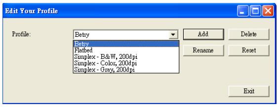
4.2.6 Editing Profiles
The Scanner Properties dialog box allows you to change and save your frequently used scan settings into a profile. You can edit these profiles by renaming or deleting them.
To add a new profile,
- Customize your settings. (For example, change your resolution, image type, cropping method, scan size, or other scan settings.)
- Click the Image tab and then choose "Profiles" to prompt the "Edit Your Profile" dialog box.
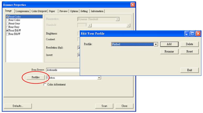
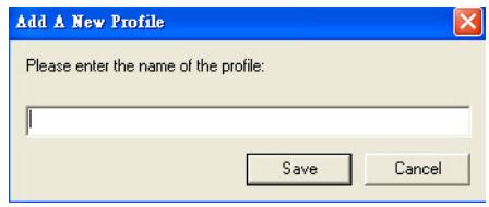
- Click "Add" to enter the name of the profile and then choose "Save".
- The new profile will be saved and shown in the "Profiles" dropdown list box.
To load a profile,
- From the Image tab dialog box, choose your favorable profile from the "Profiles" dropdown list box.
- Your favorable profile will be immediately loaded and displayed on Scanner Properties dialog box.
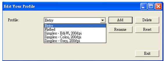
To delete a profile,
- From the Image tab dialog box, click "Profiles" to prompt the Edit Your Profile dialog box.
- Choose the profile you want to delete from the dropdown list box.
- Click "Delete". A Confirm message "Are you sure you want to delete this profile?" is prompted.
- Choose "Yes" to delete or "Cancel" to quit.
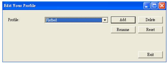
To rename a profile,
- From the Image tab dialog box, click "Profiles" to prompt the Edit Your Profile dialog box.
-
Choose the profile you want to rename from the dropdown list box and then click the Rename button.
-
Enter new name for the profile.
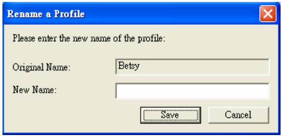
- Choose "Save" to save the new profile or "Cancel" to quit.
Note:
The preset default profiles include Flatbed, Simplex-B&W, 200 dpi, Simplex-Gray, 200 dpi, Simplex-Color, 200 dpi, Duplex-B&W, 200 dpi, Duplex-Gray, 200 dpi, Duplex-Color, 200 dpi. If you have a simplex or a sheetfed scanner, the duplex or the flatbed option will not be available.
4.3 The Compression Tab
The Compression tab allows you to compress your scanned image and choose the level of compression. Bi-tonal images are normally compressed using CCITT standard called Group 4 (G4). Color and grayscale images are often compressed using JPEG technology. Move the JPEG Quality slider to the right or left to increase or decrease the level of compression. Note the greater the compression level, the lower image quality. Default is 50% .
Note that the compression depends on your image editing application. If your image editing application does not support the type of compression format, then either a warning message will appear or the image quality of the compressed file will not be acceptable.
JPEG (Joint Photographic Editor Group). This group developed and lent their name to a file compression standard for color and grayscale images that is widely used by scanners, and software applications. On Microsoft Windows-based systems, a file with the extension .jpg has normally been compressed using this standard.
For scanning color or gray images, the following compressions are available:
None
JPEG
For scanning B&W images, the following compressions are available:
None
G4
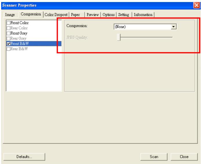
The Compression tab dialog box
4.4 The Color Dropout Tab
4.4.1 Color Dropout Selection
Color Dropout tab allows you to drop either of the red, blue, or green color in your scanned image. If your image contains red color watermark or background, choose the R (Red) channel then any red watermark or background will be removed. This feature is used to sharpen your text when using OCR (Optical Character Recognition) software.
Note that this function supports only black & white and gray images. Therefore, be sure to choose any black & white or gray image type while applying this function.
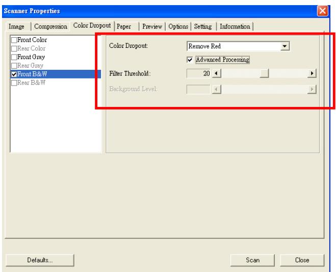
The Color Dropout dialog box
4.4.2 Other Color Dropout Options
Advanced Processing provides two options that can adjust your scanned image in the best optimal result.
Filter Threshold
This value is used to determine the color which will be dropped out. A lower value will drop more of the selected color out, while a higher value will leave more of the selected color in.
Background Level
The pixel which is higher than the background value will be adjusted to the lightest point. Adjust the value for both the Filter Threshold and Background Level to produce the best optimal result.
Example, slightly adjusting the background value makes your text more clear.
Original
Remove Blue, Threshold: 20, Background: 255
Remove Blue, Threshold: 20, Background Level: 210
4.5 The Paper Tab
The Paper tab allows you to define values relating to image output (i.e., Auto Crop or not, Scan Area, OverScan, Multi-Feed Detection).
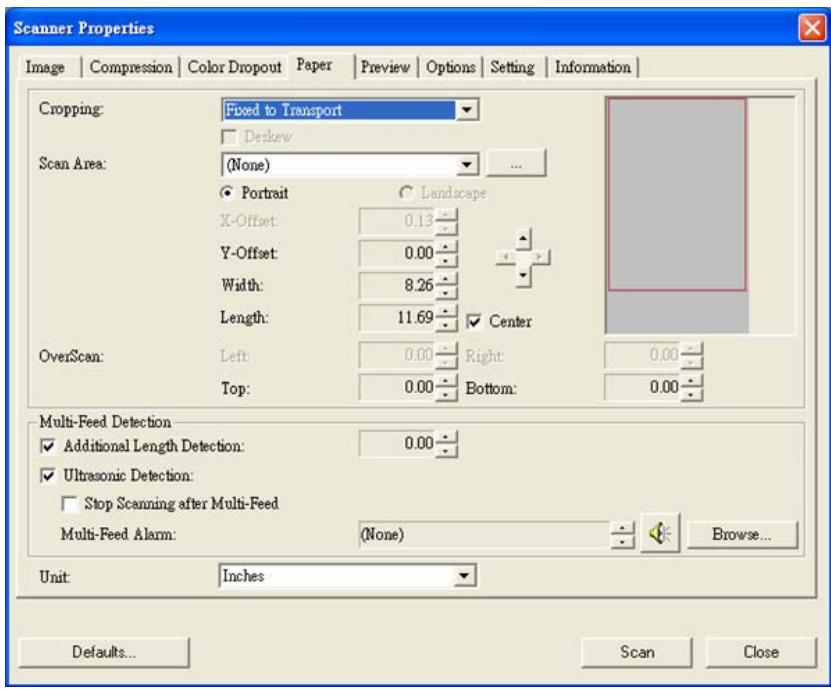
The Paper tab dialog box
4.5.1 Cropping
Cropping allows you to capture a portion of the document being scanned. Choice: Automatic, Fixed to Transport, EOP (End of Page) Detection.
| Options | Description |
| Automatic | Automatic adjusts the cropping window according to different document sizes. Use this option for batches of mixed-sized documents. |
| Fixed to Transport | This feature allows you to define the area or zone to be imaged. Use for batches of same-sized documents. If you select this option, you can use the arrow keys to define the x and y offset values, width and length to redefine your scanned area. The Display window will show image placement as you change the values. |
| EOP (End of Page) Detection | This feature allows you to define the area or zone to be imaged. Use for batches of same-width but different length documents. If you select this option, you can use the arrow keys to define the x and y offset values, width and length to redefine your scanned area. The Display window will show image placement as you change the values. |
The following options are only available when Fixed to Transport is selected.
X-Offset — the distance from the left end of the scanner to the left edge of the scanning area.
- Y-Offset — the position from the top end of the document to the top end of the scanning area.
- Width — the width of the scanning area.
Length - the length of the scanning area.
- Center: automatically calculates the x-offset for center-fed feeding based upon document size selected.
- relocate the scan area by click the arrow key on the cross sign while retain the scan size. View the result from the Display window.
Example : Redefine your scan area ( x-offset: 2.25 inches ; y-offset: 1.13 inches)
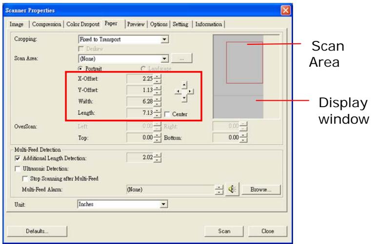
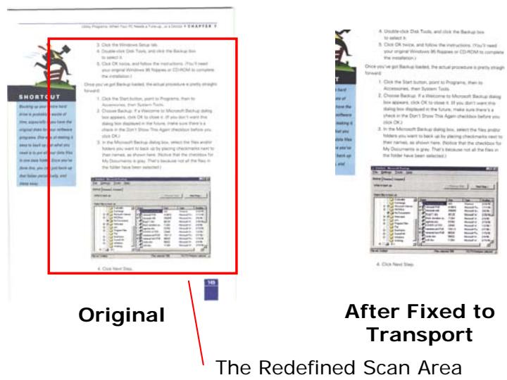
4.5.2 Other Paper Selection
Deskew
Use this option to automatically deskew a document.
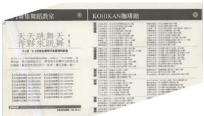
Note: If the skew angle is too great, some of the image may be cut off.
Scan Area
Choose your desired paper size with the drop-down list box. Or you may select a custom paper size by clicking the Scan Area box and then click Add to include in the choice.
Choice: None, US Letter- 8.5'' x 11", US Legal - 8.5'' x 14", ISO A4 - 21 x 29.7 cm, ISO A5 - 14.8 x 21 cm, ISO A6 - 10.5 x 14.8cm, ISO A7 - 7.4 x 10/5 cm, ISO B5 - 17.6 x 25 cm, ISO B6 - 12.5 x 17.6 cm, ISO B7 - 8.8 x 12.5 cm, JIS B5 - 18.2 x 25.7 cm, JIS B6 - 12.8 x 18.2 cm, JIS B7 - 9.1 x 12.8 cm, Scanner Maximum, Long Page.
Long Page:
When you need to scan documents whose length exceeds scanner maximum, please choose Long Page. Note if Long Page is selected, the Multi-Feed Detection will not be available. Options: Unknown Length, Enter Length (Note: This option varies due to type of scanner.)
Choose "Unknown Length" if you have a batch of long page document with unknown length. Choose "Enter Length" to enter the length and width of your documents or your desired scan size on documents. This is useful when you have a batch of documents with the same scan size or a batch of same-sized documents.
OverScan
Overscan allows you to add a specific margin at top and bottom or right and left (Options vary based on the type of scanner) of the edge of the image. This is used to reduce possible corner clipping on the skewed images and often applied to a batch of skewed document to be scanned in the auto document feeder. Select a value between 0 and +5 mm. Note the overscan result will not be shown in the Display window and that the availability of the function varies based on type of scanner.
Multi-Feed Detection
Multi-Feed Detection allows you to detect overlapped document that go through the auto document feeder. Multi-Feed usually occurs due to stapled documents, adhesives on documents, or electro-statically charged document. Note: The availability of the function varies based on type of scanner.
Additional Length Detection
Additional Length Detection allows you to define the length of document being multi-fed. This value indicates the additional length exceeding your scan area. The Display window will show the size of the document as you change the value. A value of 0 indicates no additional length detection. The Additional Length Detection is best used when scanning same-size documents in the auto document feeder.
Example : Additional Length Detection : Set Additional Length to be 2.02 inches
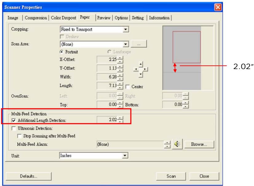
Ultrasonic Detection
Ultrasonic Detection allows you to set overlapped document by detecting paper thickness between documents. Note : The availability of the function varies based on type of scanner.
There are two options available if Multi-Feed is detected.
- Stop Scanning after Multi-Feed
If this is selected, the scanner will stop the feeder and display the following Warning dialog box if multi-feed is detected.
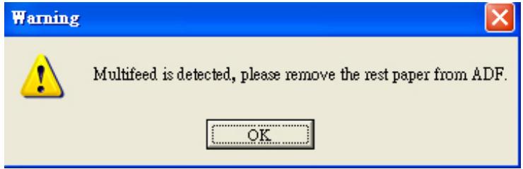
Action:
- Follow the instruction on the Warning dialog box to remove the rest pages on the feeder.
- Click OK to close the Warning dialog box.
- Scan the rest pages.
Sound Alarm on Multi-Feed
If a wave file is added, the scanner will make a sound alarm if multi-feed is detected yet no Warning dialog box will be displayed.
If "Stop Scanning after Multi-Feed" is selected, the scanner will stop the feeder.
If "Stop Scanning after Multi-Feed" has not been selected, the scanner will continue to scan till the end of your document.
Action:
-
If "Stop Scanning after Multi-Feed" is selected, follow the action described in the preceding section "Stop Scanning after Multi-Feed" on the previous page to complete your job.
-
If "Stop Scanning after Multi-Feed" has not been selected, rescan the pages where multi-feed is detected.
How to add the sound alarm :
- Click the Browse button on the right side of the speaker icon. The Open dialog box appears.
- Choose your wave file.
- Click the Open button. The wave file is added.
Units
Defines the primary measurement system. Inches, Millimeters, and Pixels are available.
4.5.3 Relative to Document
Relative to Document: (used for batches of same-sized documents)
This option allows you to crop different areas on your documents and deliver these images in B&W, Gray, or Color separately. For example, there are applications which require you to store the entire document in B&W and a part of the document in color to save storage space. This is useful for documents where a photograph, or signature appears in a consistent area on the document such as resumes, and so on.
The following procedure describes how to reproduce the entire document in B&W and a portion of document (picture) in color.
- On the Paper tab, choose "Relative to Document" or "Fixed to Transport" from the Cropping option.
- Choose your scan size from the Scan Area option. The selected scan size will be displayed in a red rectangular box. This is also the scan size of your entire document. (For example, ISO B5. If you have not chosen a scan area and leave the selection as None, then the default area will be the scanner's maximum.)
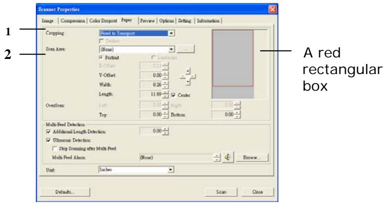
- Click the Preview tab to display the Preview window. A black rectangular box appears to indicate the max. scan size your have just selected.
The Image Selection Box
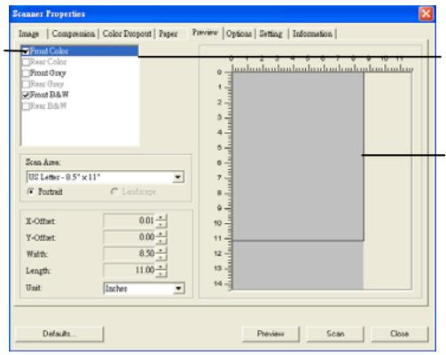
The selected image
A black rectangular box
- Click the Preview button to view the entire image in low resolution to correctly crop your relative scan area.
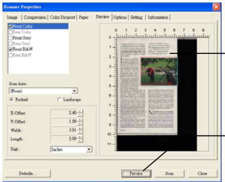
The Preview Image
The Preview Button
- Select image type from the Image Selection box. The selected image will appear in highlighted color. (For example, Front Color)
- Place your cursor on the Preview window and click your left mouse button. A cross sign will appear as illustrated. Create your relative scan size diagonally by dragging the left mouse button to your preferable size. The selected area will appear in a red box as illustrated.
A Cross Sign
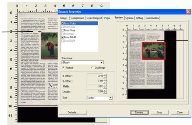
The Relative Area
- Check the B&W image from the Image Selection box to scan the entire document.
- Click the Scan button to start scanning the document in two image types and sizes. (See the result in below.)


Scotland

The entire document in B&W
The relative area in color
4.6 The Preview Tab
The Preview tab allows you to preview (a low-resolution scan) your image before final scan. This preview image lets you allocate your scan area. You can choose your scan area by the "Scan Area" drop down list box or placing your cursor on the Display window and dragging it diagonally on the Display window. Then, a red rectangle box will appear to indicate the selected area.
Note: If you choose "Automatic Cropping" on the "Paper Tab", then to select a scan area on the Preview tab is not allowed.
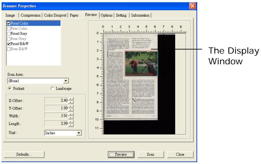
The Preview Tab
4.7 The Options Tab
The Options tab allows you to set following additional image processing settings.
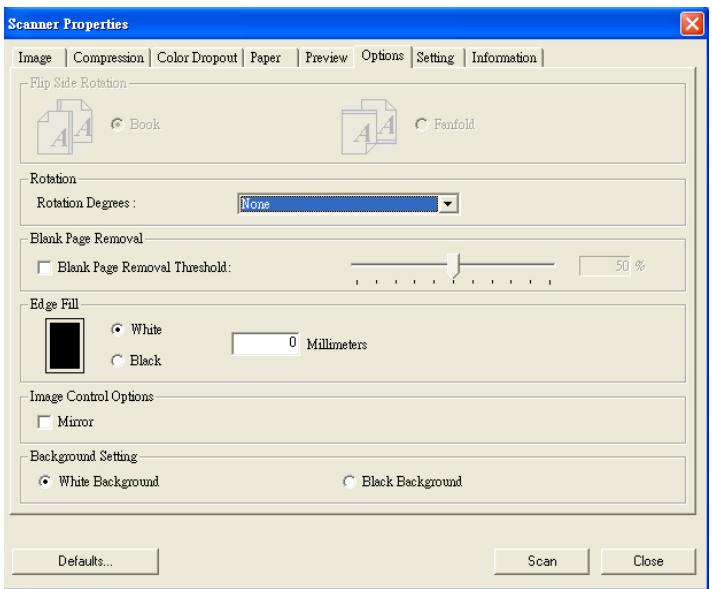
The Option tab dialog box
Flip Side Rotation
Select "fanfold" to rotate the image of the reverse side to 180 degrees.
This is applied to double-sided document which are viewed in portrait are sometime fed into the scanner in landscape or vice versa.
Choice: Book, Fanfold.
If "Book" is selected, the image of the reverse side will not be rotated.
The following illustration shows the documents which should be viewed in portrait are fed into the scanner in landscape
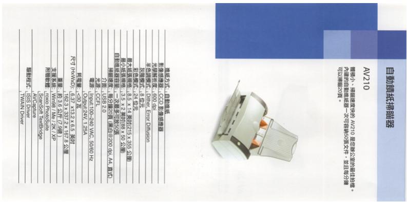
Rotate Image
Choose the rotation angle from the drop down list if you wish to rotate your scanned image.
Choice: None, 90^ CW(clockwise), 90^ CCW(counter clockwise), 180^ .
123

Original

Rotate 90^ CW

εZI
Rotate 90^ CCW
Rotate 180^
Blank Page Removal
Check if you wish to remove the blank page and move the slider to the left or right to your desired threshold.
Edge Fill
Check White or Black if you wish to add white or black edge on the border of your scanned image. Enter the value from 0 to 5mm . Default value is 0.
Original
Edge Fill: 5mm (Black)
Image Check the Mirror box if you wish to reverse the Control right and left side of your image.
Option

Original

The Mirror Effect
Background Setting
This option allows you to set your scan background.
Choice: White Background, Black Background.
*This option varies based on type of scanner and is available for the front page in the ADF (auto document feeder) only. For the rear page, only the white background is available.
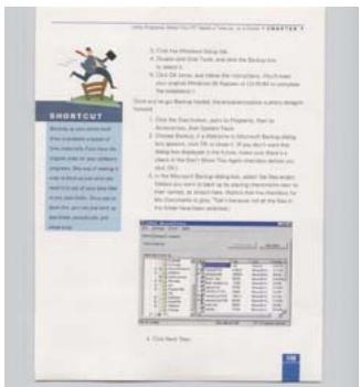
White Background
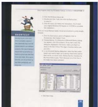
Black Background
4.8 The Setting Tab
The Setting tab allows you to set the following settings:
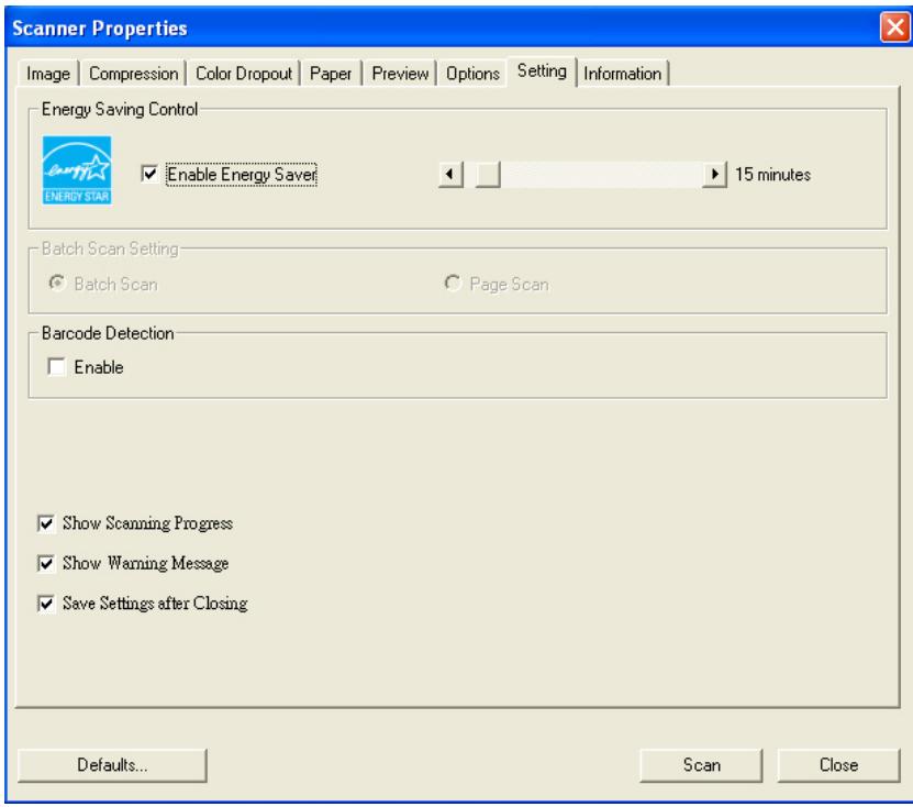
The Setting tab dialog box
| Energy Saving Control | Check the Enable Energy Saver box and move the slider to the right to set the amount of time to start the energy saver after your last action. The range is from 1 to 240 minutes. The default is 15 minutes. |
| Batch Scan Setting | ·Batch Scan To increase the scanning speed, the scanner first scans a few pages of your document and then sends these scanning data to the application. Therefore, during scanning, the numbers of pages been scanned on the scanner is somehow different with the numbers of pages displayed on your computer screen. Choose this mode if you wish to complete your scanning task at the fastest speed. ·Page Scan If you choose Page Scan, during scanning, the scanner will first scan only one page of your document and then send the scanned data to the application and then scan the next page and send the next data to the application, and so on. Therefore, in this mode, the scanning speed is slower yet this helps to keep the same scanning progress between the scanner and your computer screen. |
| Barcode Detection | Check this option to enable detecting and recognizing barcode in your document. After the detecting process, an avbarcode.ini file will be generated and stored in your system drive, for example, Windows\avbarcode.ini. Note: The availability of this feature varies based on type of scanner. |
| Show Scanning Progress | Check and the scanning progress bar will be shown during scanning. |
| Show Warning Message | Check to show the warning messages such as “ADF pad count exceeds 50,000 scans (the number varies based on type of scanner). Please replace the ADF pad and reset the pad count.” |
| Save Settings after Closing | Check to save your scanner properties settings after leaving the dialog box. Next time when you open the Scanner Properties dialog box, the previously saved settings will be shown. |
4.9 The Information Tab
The Information tab displays the following system and scanner information.
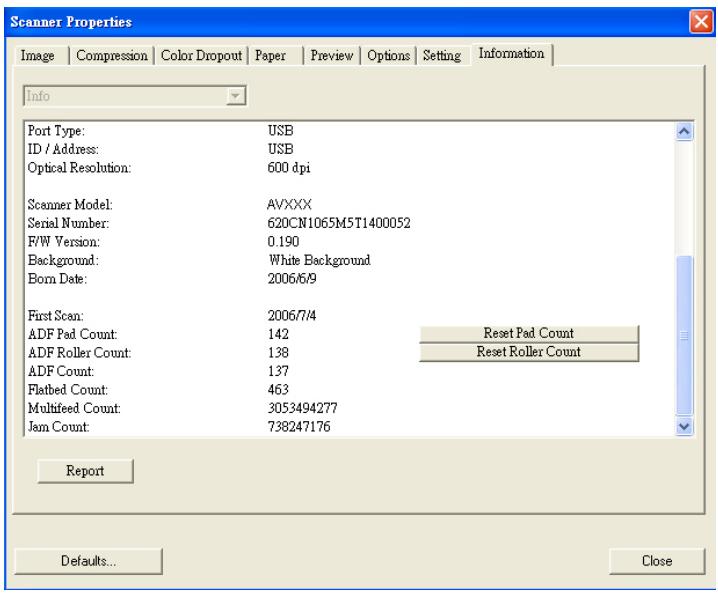
The Information tab dialog box
The "Report" button :
If you encounter any error message while using the scanner, click the Report button. A report.txt file (C:\AVxxx) will be generated. Please send this file to the nearest service center for trouble shooting.
The "Reset Pad Count" button
After scanning approximately 50,000 pages (the number varies based on type of scanner) through the Auto Document Feeder (ADF), the ADF pad may be worn out and you may experience problems with document feeding. In this case, it is highly recommended to replace the ADF pad with a new one. (Please refer to the manual for proper replacing procedure.) For ordering the ADF pad, please consult your nearest dealer. After replacing the ADF pad, click the "Reset Pad Count" button to reset the pad count.
The "Reset Roller Count" button
After scanning approximately 200,000 pages (the number varies based on type of scanner) through the ADF, the ADF roller may be worn out and you may experience problems with document feeding. In this case, it is highly recommended to replace the ADF roller with a new one. (Note the replacement of the ADF roller has to be performed only by authorized service center. Therefore, please return your scanner for roller replacement.) After replacing the ADF roller, click the "Reset Roller Count" button to reset the roller count.
Note :
The lifetime and the replacing procedure vary based on type of scanner. Please consult your nearest dealer for more details.
5. ISIS Interface Operation
The ISIS driver operation method is similar to the TWAIN's. Every function on the ISIS interface screen is briefly described as below:
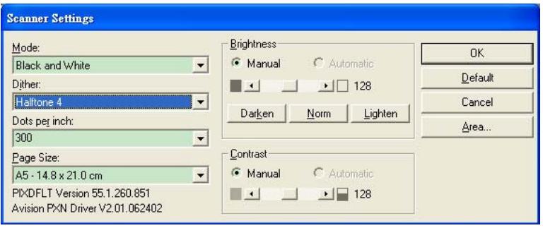
Mode: Select one of scan modes, including B&W, gray, color options.
Dither: 5 halftone levels available, can be disabled.
Dots per inch: Select your desired resolution.
Paper Size: Select your desired paper size.
Brightness: Adjust your scan image brightness or darkness.
Contrast: Adjust the range between the darkest and the lightest shades in the image.
Default: Click to reset all settings.
Area: Select your desired scan area or position.
6. Maintenance
6.1 Cleaning the ADF
The scanner is designed to be maintenance free. However, it still needs to be cleaned occasionally to ensure optimum image quality and performance.
From time to time the pad assembly and feeding rollers may become contaminated with ink, toner particles or paper dust. In this case the scanner may not feed documents smoothly or several documents may feed at once. If this occurs please follow the cleaning procedures to return your scanner to its original state.
The cleaning procedures
i). Moisten a cotton swab with isopropyl alcohol (95%). (Cleaner kits are available from PictureVision.)
ii). Carefully open the ADF to the left. Wipe the feeding rollers by moving the swab from side to side. Rotate the rollers forward with your finger and repeat the above cleaning procedures until the rollers are clean. Be careful not to snag or damage the pick springs.
iii). Wipe the pad in the direction from top to bottom. Be careful not to hook the pick springs.
iv). Close the ADF unit. Your scanner is now ready for use.
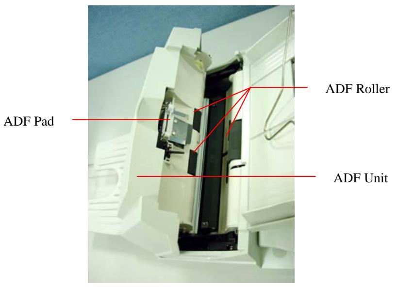
6.2 Cleaning the Glass
The procedures:
i). Soak a cotton swab with some isoprophy alcohol (95%).
ii). Open the ADF unit and document cover as shown in Figure 6-2. Wipe the glass of flatbed area and ADF area by moving the swab from side to side.
iii). Close the ADF unit and document cover. Your scanner is now ready for use.
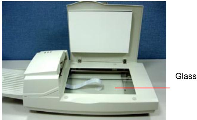
Figure 6-2 The Cleaning Area
6.3 Replacing the ADF snap-in pad module
After scanning approximately 20,000 pages through the ADF, the separation pad may be worn out and you may experience problems with document feeding. In this case, it is highly recommended to replace the pad module with a new one. For ordering the pad module, please consult your nearest dealer and follow the procedure below to replace it.
Disassembling Procedure
- Open the ADF cover.
- Remove the ADF snap-in pad module by pulling out the upper part of the pad clamp as shown in Figure 6-3.
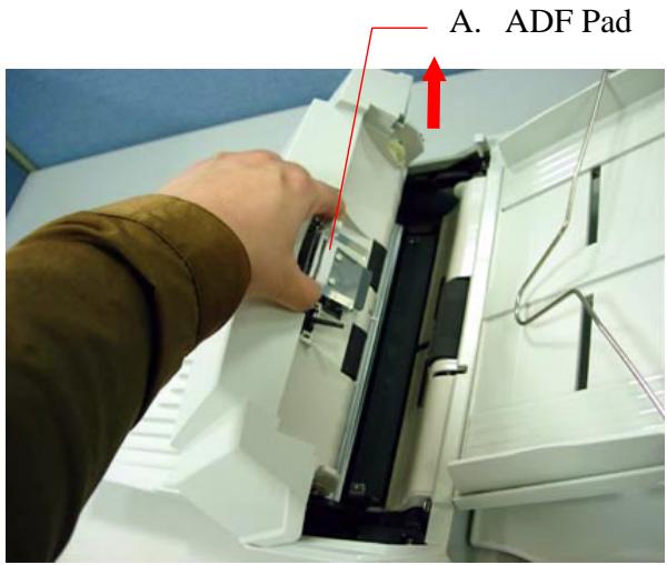
Figure 6-3 Remove the ADF Pad
Assembling Procedure
- Take out the ADF pad module from the box.
- Hold the upper part of the pad clamp and place it gently to the pad holder as shown in Figure 6-4.
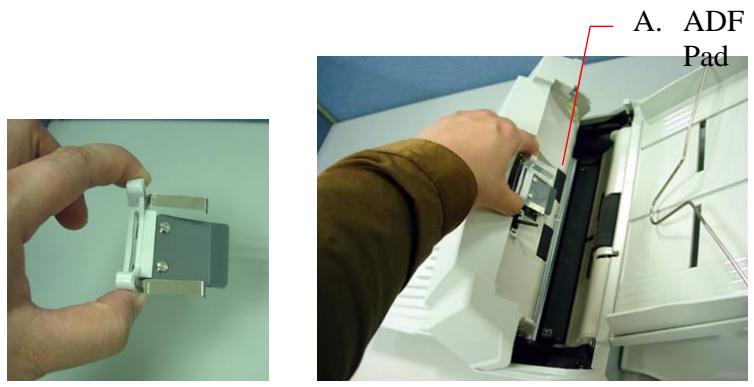
Figure 6-4 Installing the ADF Pad
6.4 Replacing the ADF Paper Feed Roller
- Open the ADF cover.
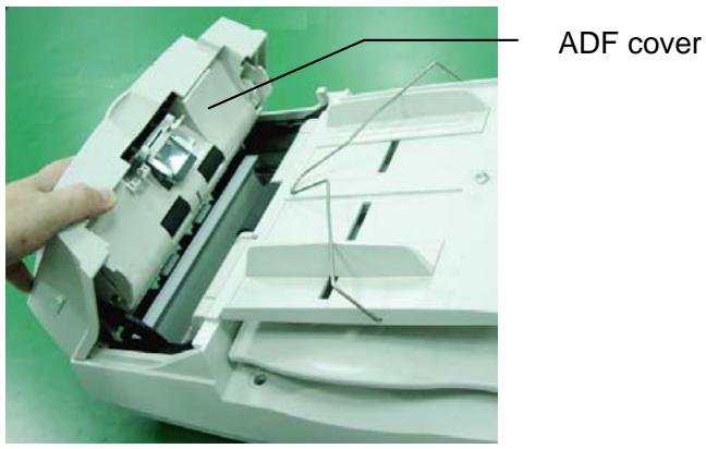
- Lift the tabs.
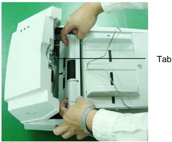
- Remove the paper feed roller cover.
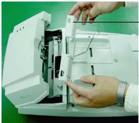
ADF roller cover
- Remove the paper feed roller.
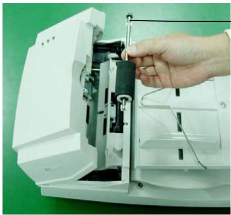
ADF paper feed roller
- Insert the new paper feed roller by aligning the tabs into the slots and pressing the roller into place.
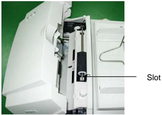
- Reinsert the paper feed roller cover and snap it into place.
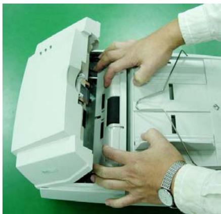
- Close the ADF cover.
7. Trouble shooting
The scanner will automatically perform a simple self-test each time it is turned on. This will help spot major system errors in the scanner itself.
When the test is initiated, the READY LED is flashing. When the test is completed, if no error occurs, the READY LED is steadily on.
If you have problems with the operation of your scanner, please check the following troubleshooting hints.
7.1 Question and Answer
Question: The LED indicates that the scanner is ready, but the scanner does not respond to the scan command from the host computer.
Answer: a) Please check if the signal cable is firmly seated, and invoke the scan command again. If there is still no response, please reset the scanner by turning it off and then on again, and reboot your host computer as well.
b) Check if the driver is correctly installed.
Question: Paper becomes jammed during scanning.
Answer: a) Open the ADF unit.
b) Pull out the jammed paper carefully.
c) Close the ADF unit.
Question: More than one sheet of paper were fed into the scanner.
Answer: a) Open ADF unit.
b) Remove the multi-fed sheets of paper.
c) Close the ADF unit.
d) Flatten the corners and edges; loosen the paper before reloading it in the paper guide.
e) Check the feeding roller condition and do the cleaning if necessary.
Question: Paper becomes skewed in the scanner.
Answer: a) Check the feeding roller condition; do the cleaning if necessary.
b) Use the paper guide when feeding the paper.
Question: When I power on the scanner, it makes noises and will not stand ready.
Answer: There are two possibilities:
a) You forgot to remove the shipping switch from the scanner. Please remove the shipping retainer first.
b) You did not place the scanner on a flat desktop surface. This may cause the scanner to function improperly.
Question: When I power on the scanner, the lamp does not light.
Answer: The possibilities are as follows:
a) The lamp is out of order. In that case, contact your authorized local dealer to change the lamp. The life time of the lamp is about 5000 hours.
b) Check whether the power LED on ADF cover steadily lights or not.
If it flashes, the power adapter malfunctions or the main board is short-circuited.
Contact your authorized local dealer to replace the power adapter or main board.
Question: Getting image from the scanner is not a problem, but when scanning, the scanner or system will often crash.
Answer: Please check
a) If the SCSI cable or the USB cable is firmly seated;
b) Only two SCSI terminators can be connected to your SCSI daisy chain. One is at the end of the SCSI device, and another is already in your host adapter.
Question: The scanned image always comes out to be too dark.
Answer: a) Use your application to modify the Gamma setting to 2.2 and 1.8 for your printer and monitor respectively.
b) Use Brightness setting from the TWAIN user interface to get a brighter image.
Question: The scanner works well otherwise, but for the line art, the lines scanned seem much thicker than those of the original.
Answer: Use the Brightness or Threshold setting to adjust the line art image.
7.2 Paper Jam in the ADF
In the event of paper jam, please follow the procedures below.
i). Open the ADF cover as shown in Figure 7-1.
ii). Pull the paper out of the ADF unit carefully.
ADF Unit
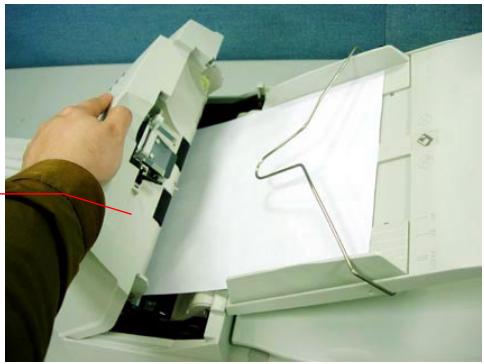
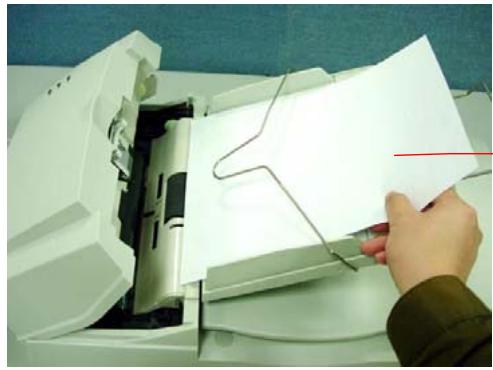
Figure 7-1 ADF Paper Jam - Removing the Paper
Document
8. Technical Service
Technical support for Avision scanner is provided at Avision Technical Assistance Center (ATAC). Before contact with ATAC, please prepare the following information.
- Scanner serial & revision number (located on the bottom of the scanner)
- Hardware configuration (e.g., your host CPU type, RAM size, free disk space, display card, interface card, etc.)
- The name and version of your software application
The version of your scanner driver.
Please call us at:
US and Canada Area: Avision Labs., Inc.
Address: 6815 Mowry Ave. Newark CA 94560, USA
Telephone: +1 (510) 739-2369
Fax number: +1 (510) 739-6060
Web Site: http://www.avision.com
E-mail: support@avision-labs.com
Other Area: Avision Inc.
Address: No.20, Creation Road I, Hsinchu Science Park, Taiwan, R.O.C.
Telephone: +886 (3) 578-2388
Fax number: +886 (3) 577-7017
Web Site: http://www.avision.com
Email: service@avision.com.tw
9. Specifications
Model Number
300500001
(Simplex Scanner)
300500002
Duplex Scanner)
Scanning Mode
B&W
Gray
Color
Optical
600 x 600 dpi
Resolution
Light Source
Cold Cathode fluorescent lamp
ADF Capacity
50 sheets
Scan Area
Flatbed: up to European A4
(8.5^ × 11.69^ )
ADF: 3.7'' × 5.5'' (Min)
ADF: 8.5'' × 14'' (Max)
Interface
SCSI-2/USB 2.0
Power
24Vdc/2A
Requirement
Power
< 48 watts
Consumption
Operation
5^ C to 35^ C
Temperature
Storage
-40°C to 60°C
Temperature
Dimension
567 × 350 × 199 mm
Weight
7.2 kg (15.87 lbs)