
VISIONMOUNT FLAT PANEL WALL MOUNT-VMPL2 - Wall mount for flat screen SANUS - Free user manual and instructions
Find the device manual for free VISIONMOUNT FLAT PANEL WALL MOUNT-VMPL2 SANUS in PDF.

| Product Type | Wall mount for flat screen |
| Brand | SANUS |
| Model | VISIONMOUNT VMPL2 |
| Maximum load capacity | 79.4 kg |
| Adjustable tilt | Flat (0°) or tilted 5° downward |
| Compatible wall types | Wood stud, brick, monolithic concrete, concrete block |
| Mounting hardware included | Yes (screws, anchors, washers, spacers) |
| Number of wall attachment points | 4 (wood stud) or 6 (concrete/brick/block) |
| Safety bar included | Yes |
| Required tools | 3/16" drill bit, 1/2" masonry bit, socket wrench, Phillips screwdriver |
| Minimum drilling depth | 6.4 cm |
| Minimum distance between studs (wood stud) | 30.5 cm |
| Maintenance | Clean with a soft, dry cloth |
| Safety | Use the safety bar and a padlock (not included) to secure the television |
| Replacement parts | Available from SANUS customer service |
| Warranty | Not specified in the manual |
Frequently Asked Questions - VISIONMOUNT FLAT PANEL WALL MOUNT-VMPL2 SANUS
User questions about VISIONMOUNT FLAT PANEL WALL MOUNT-VMPL2 SANUS
0 question about this device. Answer the ones you know or ask your own.
Ask a new question about this device
Download the instructions for your Wall mount for flat screen in PDF format for free! Find your manual VISIONMOUNT FLAT PANEL WALL MOUNT-VMPL2 - SANUS and take your electronic device back in hand. On this page are published all the documents necessary for the use of your device. VISIONMOUNT FLAT PANEL WALL MOUNT-VMPL2 by SANUS.
USER MANUAL VISIONMOUNT FLAT PANEL WALL MOUNT-VMPL2 SANUS
International Assembly Instructions for model VMPL2
sues
THE UNION OF FORM AND FUNCTION
Assembly Instructions for VMPL2 Flat Panel Wall Mount
Thank you for choosing a Sanus Systems Vision Mount Wall Mount. This product is designed to mount flat panel televisions weighing up to 175 lb. to a vertical wall. It allows you to mount your television flat against the wall or at a fixed 5 degree tilt.
Safety Warning: If you do not understand these directions, or have any doubts about the safety of the installation, please call a qualified contractor or contact Sanus at 800.359.5520 (US) or 31 (0)20 5708938 (Europe). You can also visit our web site at www.sanus.com. We can quickly assist you with installation questions and missing or damaged parts. Replacement parts for Sanus products purchased through authorized dealers will be shipped directly to you. Check carefully to make sure there are no missing or defective parts. Never use defective parts. Improper installation may cause damage or serious injury. Do not use this product for any purpose that is not explicitly specified by Sanus Systems. Sanus Systems can not be liable for damage or injury caused by incorrect mounting, incorrect assembly, or incorrect use. Note: The supplied wall mounting hardware is not for steel stud walls or old cinder block walls. If you are uncertain about the nature of your wall, consult an installation contractor. Sanus makes every effort to assure all necessary television mounting hardware is included. If the hardware you need is not included please consult your local hardware store or call Sanus Systems.
Required Tools: 3/16 drill bit, 1 / 2 Masonry Bit for brick concrete or concrete block installations, wrench or socket set, Phillips screw driver.
Supplied Parts:
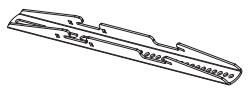

(2) Monitor Bracket - c
(4) Gusset - d
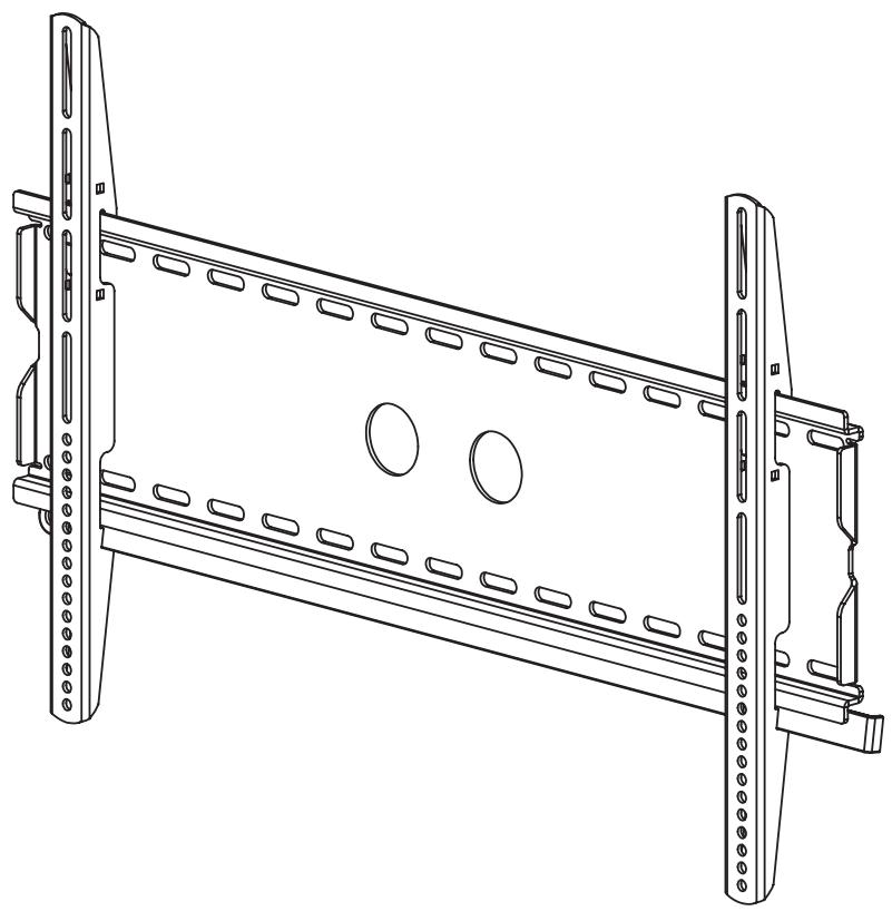
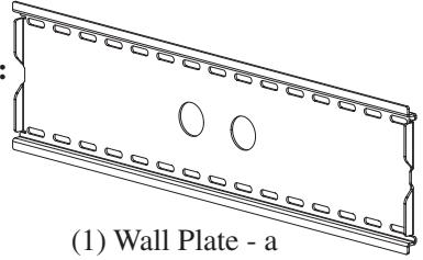
(1) Wall Plate - a
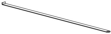
(1) Safety Bar - b
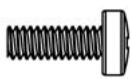
(4) M4 x 12 Bolt - e
(4) M4 x 30 Bolt - f
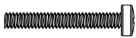
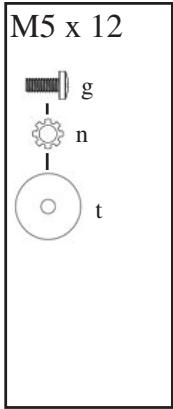
(4) M5 x 12 Bolt - g
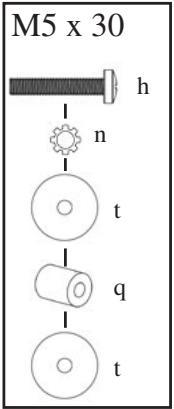
(4) M5 x 30 Bolt - h
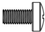
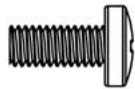
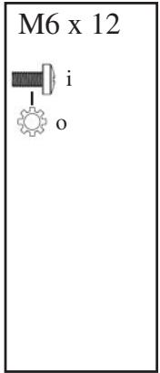
(4) M6 x 12 Bolt - i
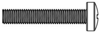
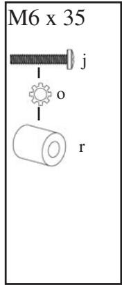
(4) M6 x 35 Bolt - j
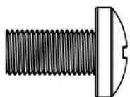
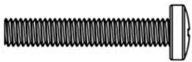
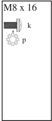
(4) M8 x 16 Bolt - k
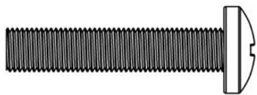
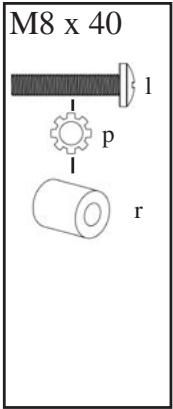
(4) M8 x 40 Bolt - 1

(4) M4 Lock Washer - m

(4) M5 Lock Washer - n

(4) M6 Lock Washer - o

(4) M8 Lock Washer - p
Step 1: Mounting the Wall Plate: Wood Stud, Brick, Solid Concrete, and Concrete Block mounting options are provided.
Wood Stud mounting:
The Wall Plate (a) must be mounted to two wood studs at least 12" apart. Use a high quality stud sensor to locate two adjacent studs. It is a good idea to verify where the studs are located with an awl or thin nail shown in Diagram 1a. Pre-drill a 2.5" deep hole at the desired height in each stud using a 3/16" drill bit. Make sure these holes are in the center area of the studs and level with each other. Use the Wall Plate as a template to mark the location of the second hole in each stud. Drill 2.5" deep holes using the 3/16" drill bit in the marked location. Attach the Wall Plate to the wall using the four 1/4 × 2.5 ” Lag Bolts (u) and four Lag Bolt Washers (s). Make sure the Wall Plate is oriented so the flat surface in the center of the plate is against the wall and that a set of Lag Bolts is on each side of the two large holes in the center as shown in Diagram 1b.
Brick, Solid Concrete and Concrete Block mounting:
Use the Wall Plate (a) as a template to mark 6 hole locations on the wall. The outer holes must fall to left and right of the two large holes in the middle of the plate. Three in the top row of slots and three more in the bottom row. Make sure these holes are level and there is at least 6'' between any two holes. Pre-Drill these holes with a 1/2'' masonry bit to at least 2.5'' in depth. Insert a Concrete Anchor (v) into each of these holes. Make sure the anchor is seated completely flush with the concrete surface even if there is a layer of drywall or other material in front. Attach the Wall Plate to the wall using 6 Lag Bolts (u) and 6 Lag Bolt Washers (s).
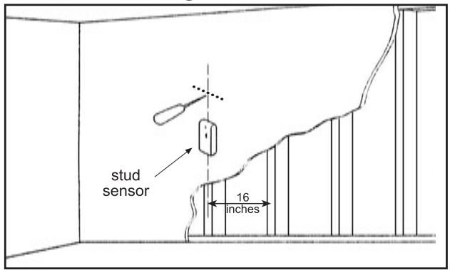
Diagram 1a
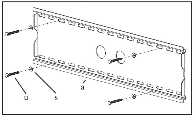
Diagram 1b
Step 2: Select the Appropriate Hardware for your television
Always make sure the television is unplugged before threading any bolt into the back panel!
Thread bolts carefully into your television by hand before tightening. If you feel resistance, remove the bolt immediately! If you are unable to find appropriate hardware for your television, consult a local hardware store or call Sanus Systems.
Locate the threaded inserts on the back of your flat panel television and determine which of the provided Bolts is the correct diameter. To test each diameter, thread the Bolts carefully into your television by hand until you find the diameter that correctly fits.
Next, determine the correct length of the required Bolt. Televisions with a flat back will require one of the shorter Bolts without a spacer. Some televisions have a curved back or have recessed threaded inserts. This may require a longer Bolt along with a Spacer placed between the television and the Monitor Bracket.
Once you have the correct bolt picked out, you can follow the diagrams below to see what additional hardware you will need to mount the Monitor Brackets (c) to your television. For a television with a flat back, see Step 3 for installation instructions. For a television with a curved back see Step 4. For a television that has a back with recessed threaded inserts see Step 5.
Hardware Diagrams:
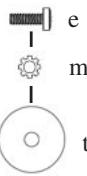
M4 x 12
WARNING: DO NOT LAY THE TELEVISION FACE DOWN ON THE GLASS, lean it up against a wall or other solid surface! Laying the television down on the glass may cause permanent damage.
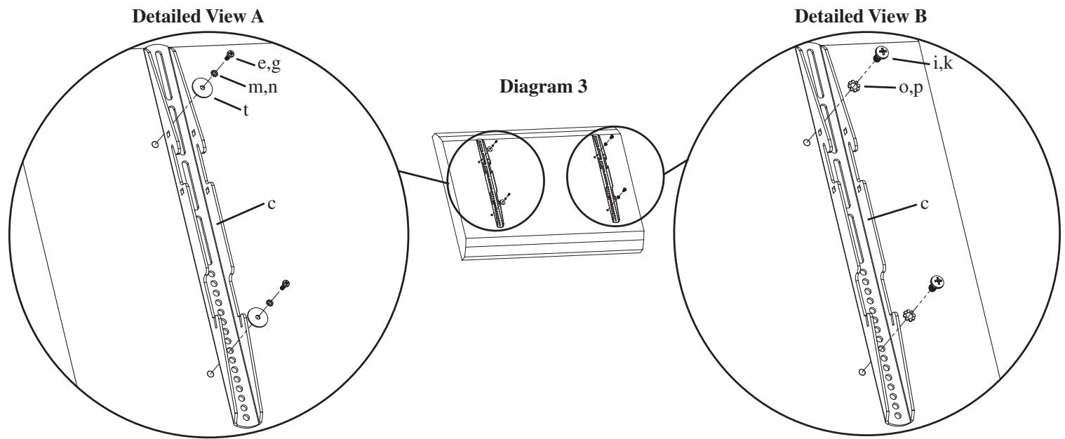
The Monitor Brackets (c) should be placed as vertically close to center of the television as possible before installation. For a flat back TV that requires the M4 or M5 diameter Bolt, thread a M4 x 12 (e) or a M5 x 12 (g) Bolt through the appropriate Lock Washer (m,n), an M4/ M5 Washer (t), the Monitor Bracket and finally into the TV. See Detailed View A of Diagram 3 for assistance. If your TV requires the M6 or M8 diameter Bolt thread a M6 x 12 (i) or a M8 x 16 (k) Bolt through the appropriate Lock Washer (o,p), through the Monitor Bracket and into the TV. See Detailed View B of Diagram 3 for assistance. Proceed to tighten the Bolts firmly with a phillips screw driver.
Step 4: Attaching the Monitor Brackets to a television with a curved back
WARNING: DO NOT LAY THE TELEVISION FACE DOWN ON THE GLASS, lean it up against a wall or other solid surface! Laying the television down on the glass may cause permanent damage.
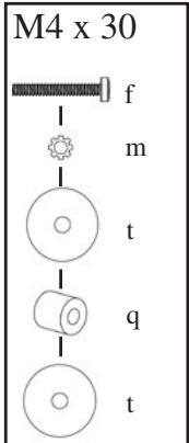
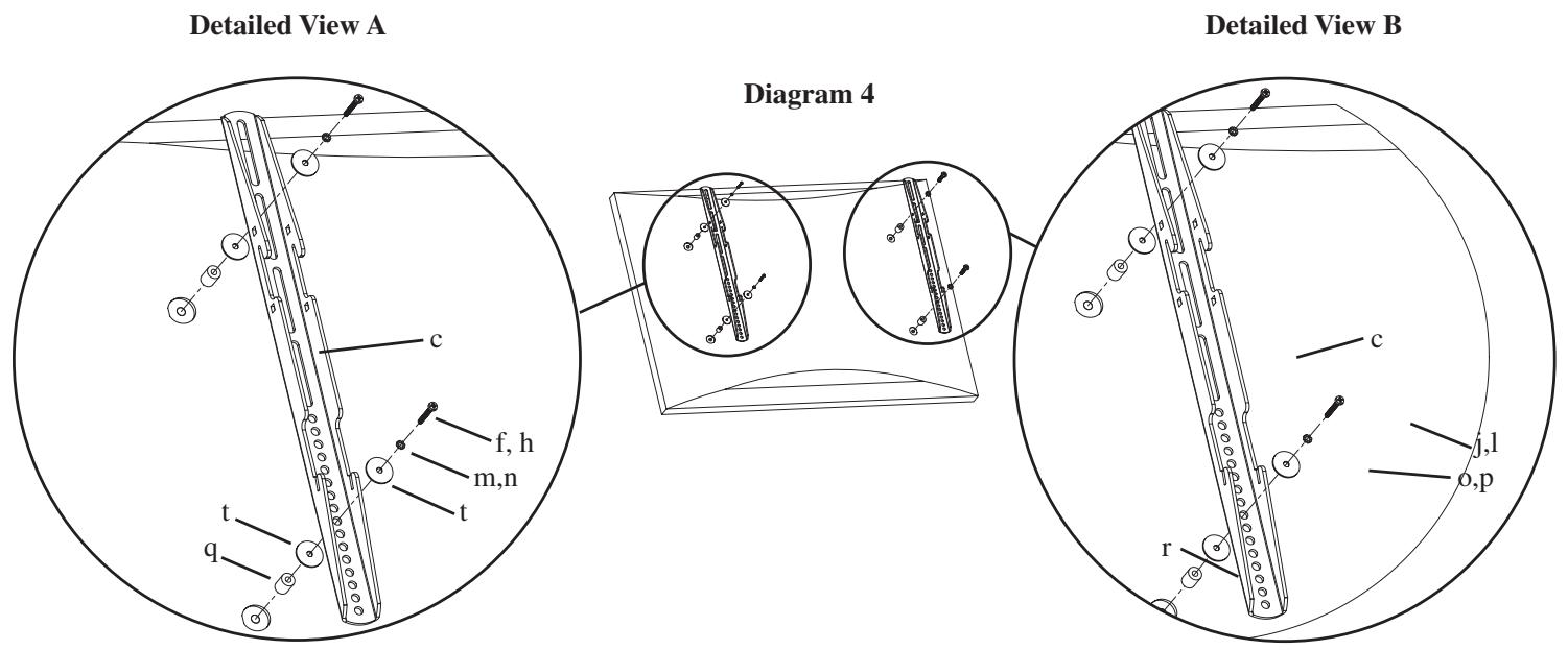
The Monitor Brackets (c) should be placed as vertically close to center of the television as possible before installation. If your TV has a curved back and requires either a M4 or M5 diameter bolt, thread a M4 x 30 (f) or a M5 x 30 (h) Bolt through the appropriate Lock Washer (m,n), an M4/M5 Washer (t), the Monitor Bracket, an M4/M5 Washer, a M4/M5 Spacer (q) and into the TV as seen in Detailed View A of Diagram 4. If you determined that your TV requires a Bolt with a M6 or M8 Diameter, thread a M6 x 35 (j) or a M8 x 40 (l) Bolt through the appropriate Lock Washer (o,p), the Monitor Bracket, a M6/M8 Spacer (r) and into the TV as seen in Detailed View B of Diagram 4. Proceed to tighten the Bolts firmly with a phillips screw driver.
Step 5: Attaching the Monitor Brackets to a television with recessed threaded inserts.
WARNING: DO NOT LAY THE TELEVISION FACE DOWN ON THE GLASS, lean it up against a wall or other solid surface! Laying the television down on the glass may cause permanent damage.
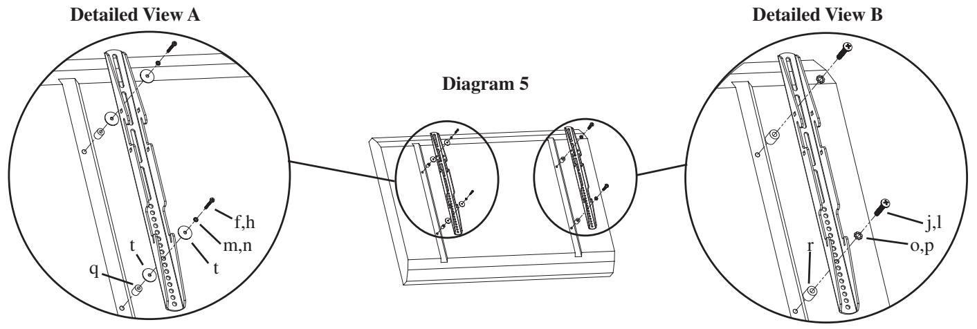
The Monitor Brackets (c) should be placed as vertically close to center of the television as possible before installation. If your TV has threaded inserts that are recessed and requires either a M4 or M5 diameter bolt, thread a M4 x 30 (f) or a M5 x 30 (h) Bolt through the appropriate Lock Washer (m,n), an M4/M5 Washer (t), the Monitor Bracket, an M4/M5 Washer, a M4/M5 Spacer (q) and into the TV as seen in Detailed View A of Diagram 5. If you determined that your TV requires a Bolt with a M6 or M8 Diameter, thread a M6 x 35 (j) or a M8 x 40 (l) Bolt through the appropriate Lock Washer (o,p), the Monitor Bracket, a M6/M8 Spacer (r) and into the TV as seen in Detailed View B of Diagram 5. Proceed to tighten the Bolts firmly with a phillips screw driver.
Step 6: Choose mounting position:
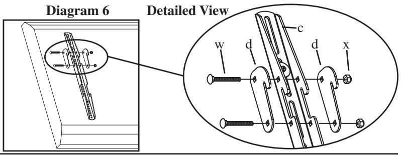
You can mount your television in either of two positions: flat or at a 5 degree downward tilt. To mount the television flat to the wall use only the Monitor Brackets (c). To mount the television in the 5 degree tilt position you must first add two Gussets (d) to each Monitor Bracket with two Carriage Bolts (w) and two Gusset Nuts (x) as shown in Diagram 6.
Step 7: Hang the TV onto the Wall Plate:
First hook the Monitor Brackets (c) over the top of the Wall Plate (a), then let the bottom of the Monitor Brackets rotate in under the bottom of the Wall Plate. This process is shown with the flat mount option in Diagram 7a, and with the 5 degree tilt option in Diagram 7b. Once the TV is in place, insert the Safety Bar (b) into the slots in the bottom of the Monitor Brackets so that it sits behind the bottom tab on the Wall Plate as shown in Diagram 7c. The bend should face toward the wall. Once the bar passes out the other side of the Wall Plate a padlock can be added to the hole in the Safety Bar for additional security.
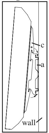
Diagram 7a
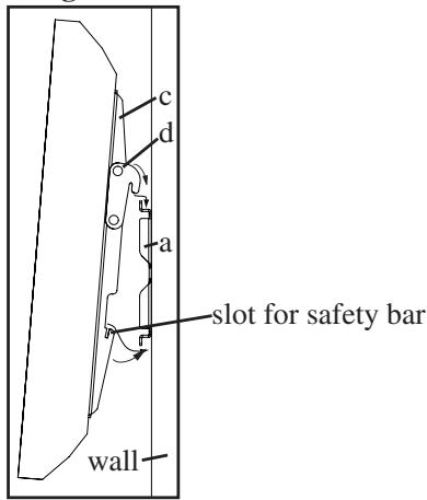
Diagram 7b
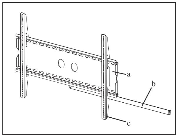
Diagram 7c