
VISIONMOUNT FLAT PANEL WALL MOUNT-VMDD26 - TV wall mounts SANUS - Free user manual and instructions
Find the device manual for free VISIONMOUNT FLAT PANEL WALL MOUNT-VMDD26 SANUS in PDF.

| Product Type | TV Wall Mount |
| Brand | SANUS |
| Model | VISIONMOUNT VMDD26 |
| Screen Compatibility | Up to 63 inches (160 cm) |
| Maximum Supported Weight | 79.4 kg |
| Material | Steel |
| Maximum Wall Distance | 65.4 cm |
| Tilt | +5° to -15° |
| Leveling Rotation | ±6° |
| Compatible Wall Type | Wood studs (studs spaced 30.5 cm minimum) |
| Required Tools | 3/16 in. drill bit, wrench set, Phillips screwdriver |
| Box Contents | Wall plate, arms, monitor brackets, clamps, tubes, hardware, Allen key, cable ties |
| Installation | Recommended for two people |
| Safety | Wall must support 5 times the weight of the TV and mount |
| Customer Service | 800.359.5520 (U.S.), 31 (0) 20 5708938 (Europe) |
Frequently Asked Questions - VISIONMOUNT FLAT PANEL WALL MOUNT-VMDD26 SANUS
User questions about VISIONMOUNT FLAT PANEL WALL MOUNT-VMDD26 SANUS
0 question about this device. Answer the ones you know or ask your own.
Ask a new question about this device
Download the instructions for your TV wall mounts in PDF format for free! Find your manual VISIONMOUNT FLAT PANEL WALL MOUNT-VMDD26 - SANUS and take your electronic device back in hand. On this page are published all the documents necessary for the use of your device. VISIONMOUNT FLAT PANEL WALL MOUNT-VMDD26 by SANUS.
USER MANUAL VISIONMOUNT FLAT PANEL WALL MOUNT-VMDD26 SANUS
International Assembly Instructions for model VMDD26
SANUS SYSTEMS
THE UNION OF FORM AND FUNCTION
Assembly Instructions for Model: VMDD26
Thank you for choosing a Sanus Systems Vision Mount wall mount. The VMDD26 is designed to mount up to 63" Flat panel televisions weighing up to 175 lb. to a vertical wall. It allows you to tilt the television from +5^ to -15^ . It will also extend 25.75" away from the wall, swivel up to ± 75^ , and roll ± 6^ .
Safety Warning: If you do not understand these directions, or have any doubts about the safety of the installation, please call a qualified contractor or contact Sanus at 800.359.5520 or www.sanus.com. Our customer service representatives can quickly assist you with installation questions and missing or damaged parts. Replacement parts for products purchased through authorized dealers will be shipped directly to you. Check carefully to make sure that there are no missing or defective parts. Never use defective parts. Improper installation may cause damage or serious injury. Do not use this product for any purpose that is not explicitly specified by Sanus Systems. Sanus Systems can not be liable for damage or injury caused by incorrect mounting, incorrect assembly, or incorrect use. Please call Sanus Systems before returning products to the point of purchase.
Note: The supplied wall mounting hardware is not for metal stud, concrete, brick or old cinder block walls. If you are uncertain about the nature of your wall, consult an installation contractor. Sanus makes every effort to assure all necessary television mounting hardware is included. If the hardware you need is not included please consult your local hardware store or call Sanus Systems.
Note: Wall must be capable of supporting 5 times the weight of the television plus the wall mount!
Required Tools: 3/16" drill bit, wrench set, phillips screw driver.
Supplied Parts: *Some parts not shown at same scale
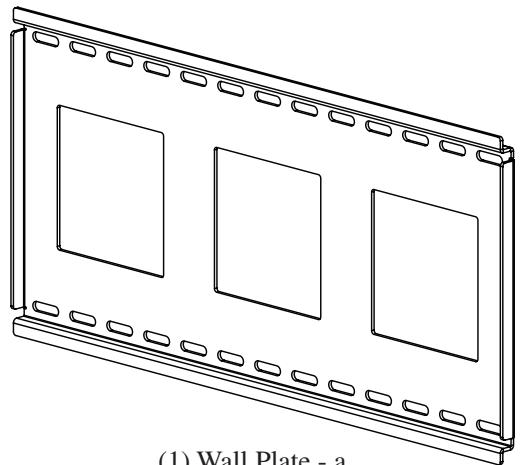
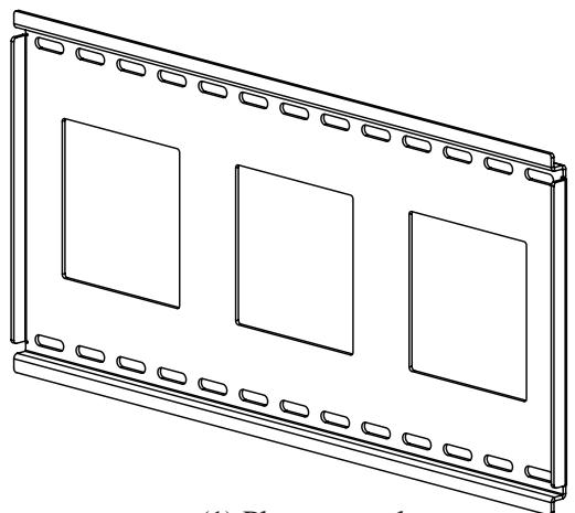
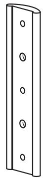
(1) Wall Plate - a
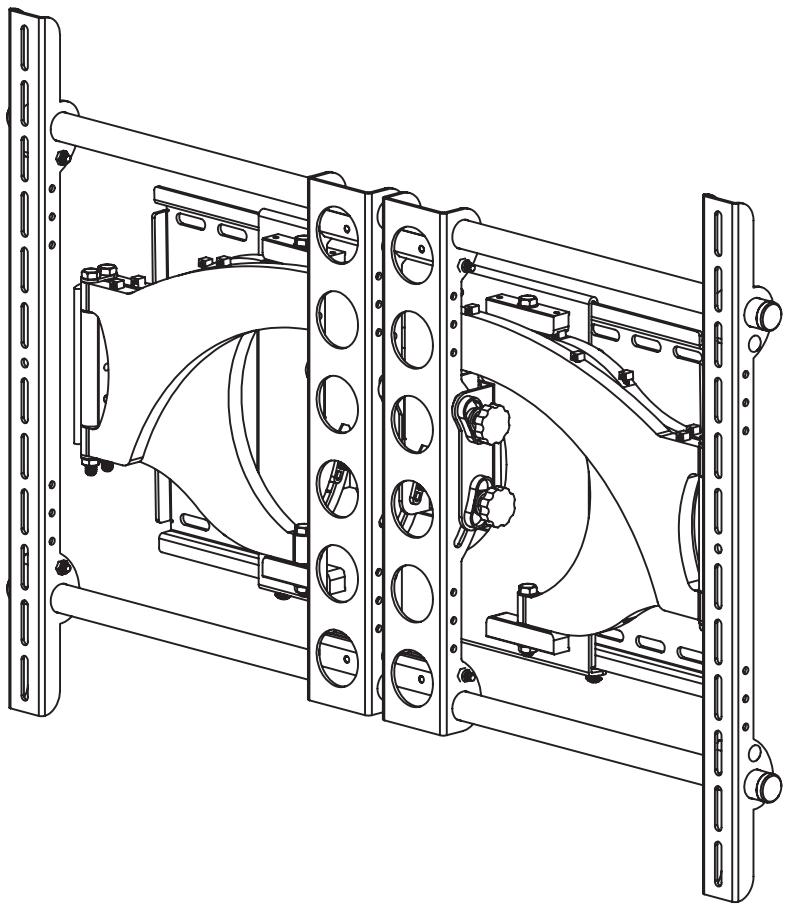
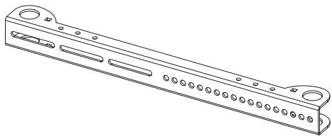
(1) Arm Assembly - b
(1) Preventor - c*
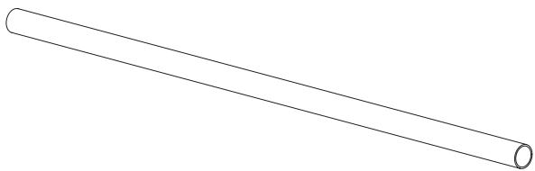
(2) 1" Diameter Tube - d
(2) Monitor Bracket - e
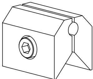
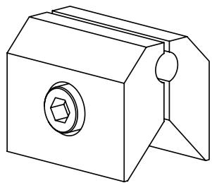
(4) Vise Assembly - f*
Hardware: Hardware shown is actual size
(7) Wire Tie Clip - g
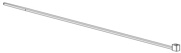
(10) Wire Tie -h*
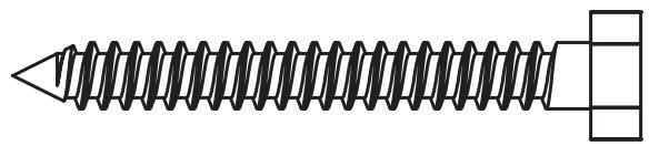

(4) Lag Bolt - i
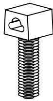
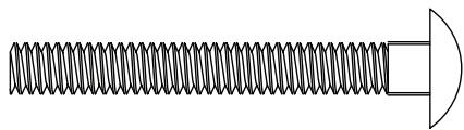
(4) 2" Carriage Bolt - 1

(4) Lag Bolt Washer - j
(4) 1 / 4 - 20Nut - m
(3) Safety Bolt - n
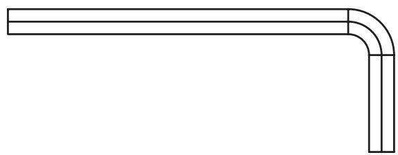
(1) Allen Key - k
(2) Preventor Bolt - o
Supplied Television Mounting and Assembly Hardware: Hardware shown is actual size
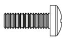
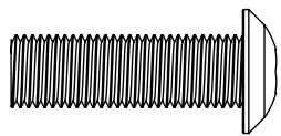
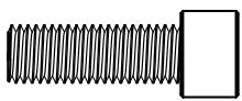
(4) M4 x 12mm Bolt - p
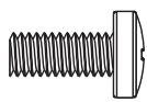
(4) M5 x 12mm Bolt - q
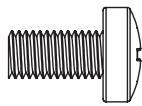
(4) M6 x 12mm Bolt - r
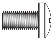
(4) M8 x 16mm Bolt - s

(4) M4 x 30mm Bolt - t
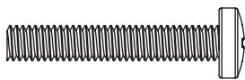
(4) M5 x 30mm Bolt - u
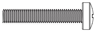
(4) M6 x 35mm Bolt - v
(4) M8 x 40mm Bolt - w

(4) M4 Lock Washer - x

(4) M5 Lock Washer - y

(4) M6 Lock Washer - z

(4) M8 Lock Washer - aa
(4) M6/M8 Washer - ee
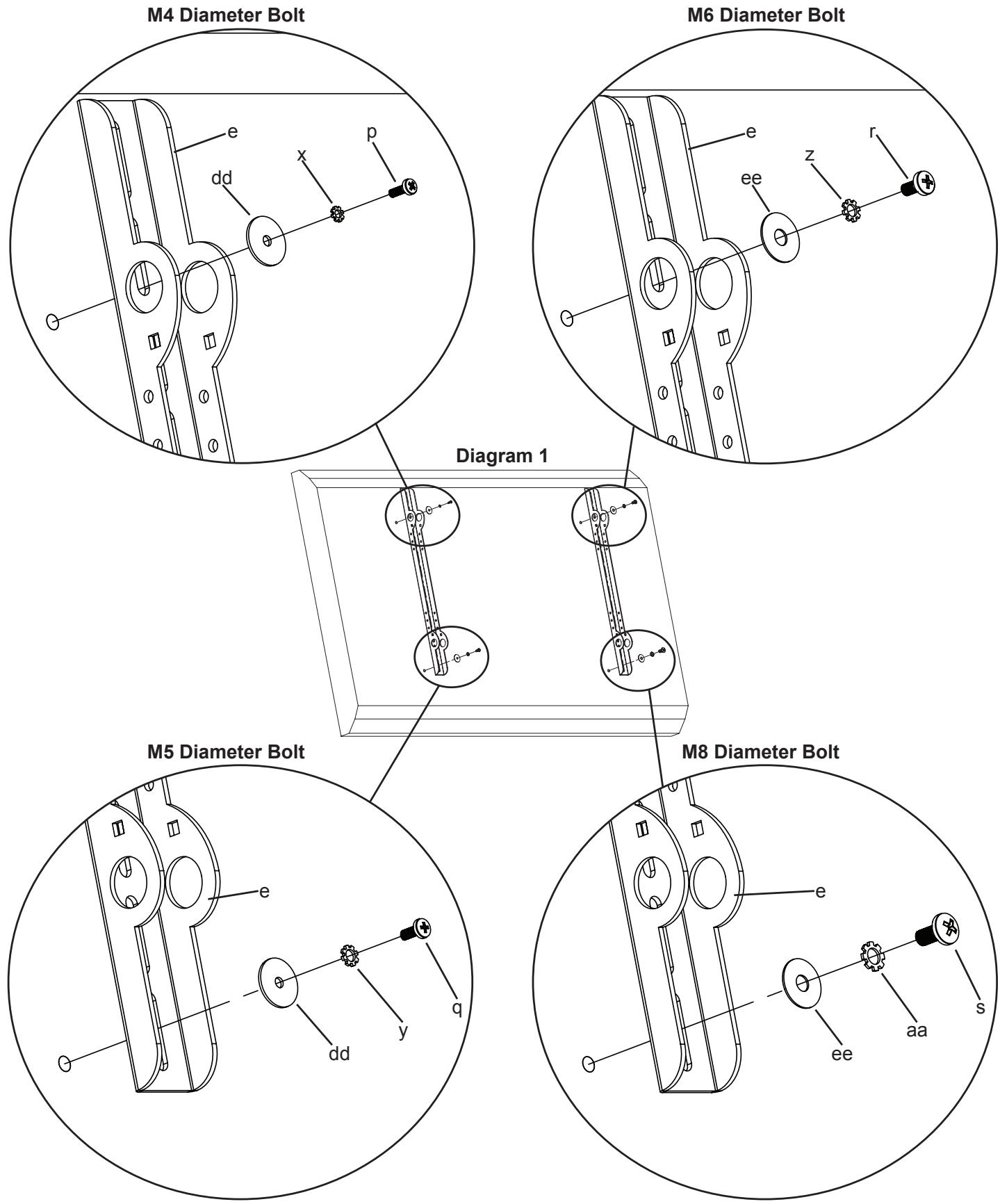
Step 1: Mounting Monitor Brackets to a television with a Flat Back
First, determine the diameter of the Bolt (p,q,r,s) your TV requires by hand threading them into the threaded insert on the back of the TV. If you encounter any resistance stop immediately! Once you have determined the correct diameter, see the appropriate Diagram below. You will thread the Bolt through the appropriate Lock Washer (x,y,z,aa), a Washer (dd,ee), the Monitor Bracket (e), and finally into the TV. Make sure the Monitor Brackets are vertically centered and level with each other.
Note: For TVs with a curved back or any other obstruction See Step 2. After completing this step, proceed to Step 3.
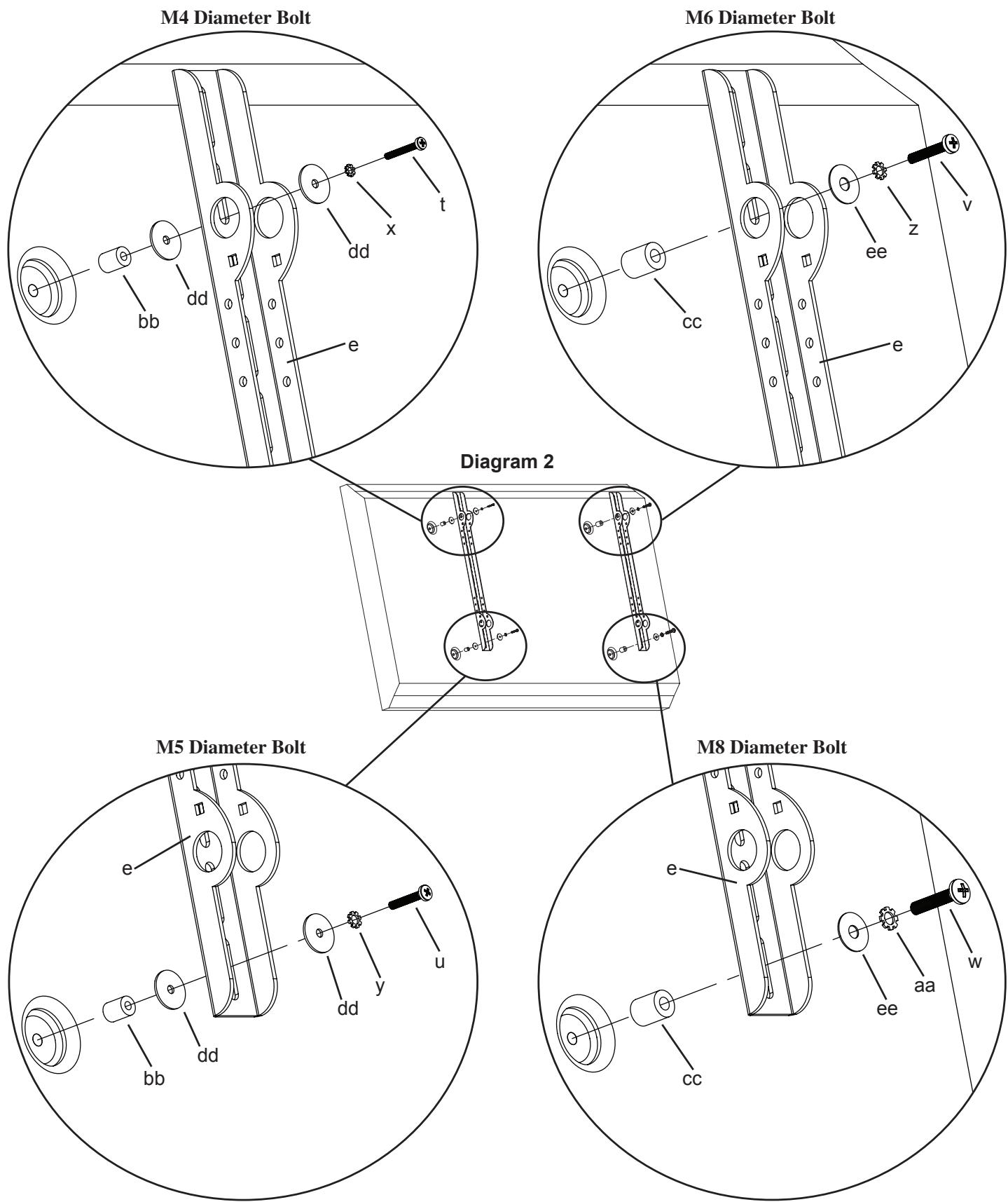
Step 2: Mounting the Monitor Brackets to a television with a curved back or any other obstruction.
First, determine the diameter of the Bolt (t,u,v,w) your TV requires by hand threading them into the threaded insert on the back of the TV. If you encounter any resistance, stop immediately! Once you have determined the correct diameter, see the appropriate Diagram below. You will thread the Bolt through the appropriate Lock Washer (x,y,z,aa), a Washer (dd,ee), the Monitor Bracket (e), a spacer (bb,cc) and finally into the TV. For the M4 or M5 diameter bolt, you will need another M4/M5 Washer between the Monitor Bracket and the Spacer. Make sure the Monitor Brackets are vertically centered on the TV and level with each other.
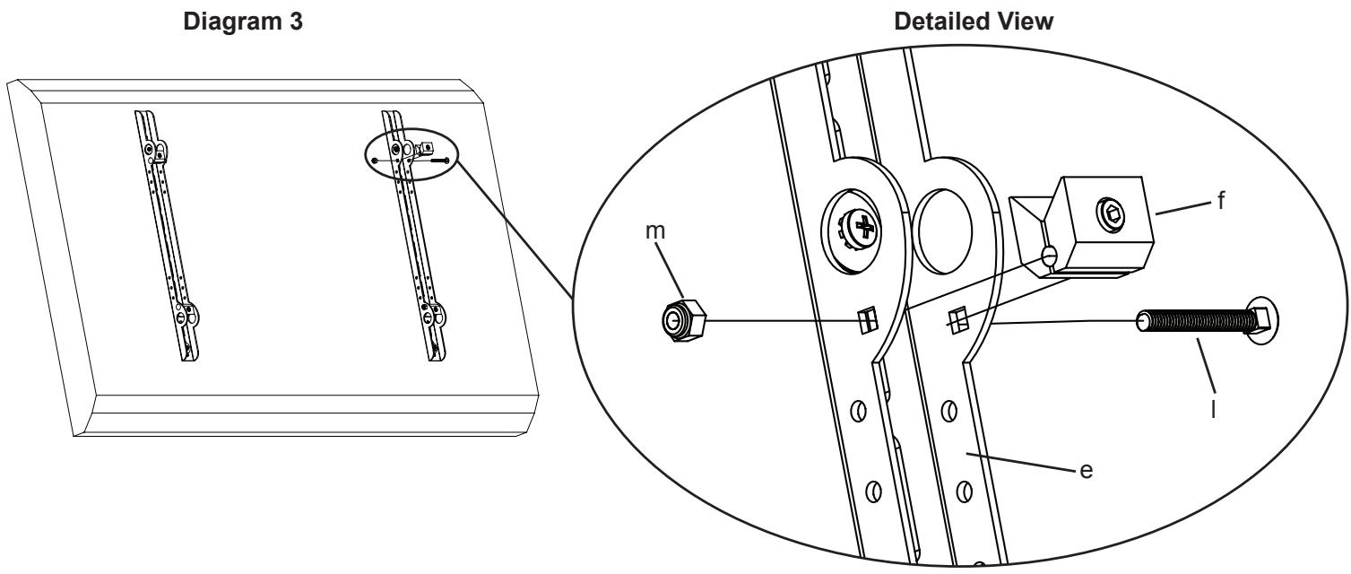
Step 3: Add the Vise Assemblies to the Monitor Brackets:
Note: Do not overtighten the 1/4-20 Nut. The Vise Assembly should be able to rotate freely around the Carriage Bolt.
Place the Vise Assembly (f) between the two sides of the Monitor Bracket (e) so that the two jaws point toward the set of 1” diameter holes and the allen bolt is facing away from the television as shown in the Detailed View of Diagram 3. Place a 2” Carriage Bolt (l) through the square hole in the side of the Monitor Bracket, through the hole in the Vise Assembly, and then through the square hole in the other side of the Monitor Bracket also shown in the Detailed View of Diagram 3. Next, tighten a 1/4-20 Nut (m) onto the end of the 2” Carriage bolt. Repeat this step for the bottom of the Monitor Bracket. Finally, repeat these two steps for the second Monitor Bracket.
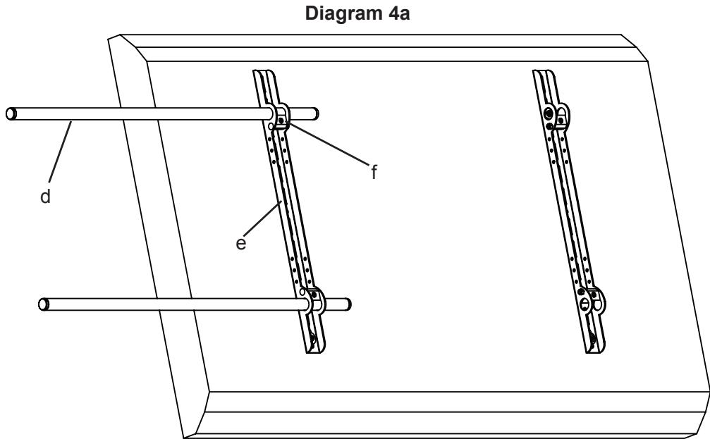
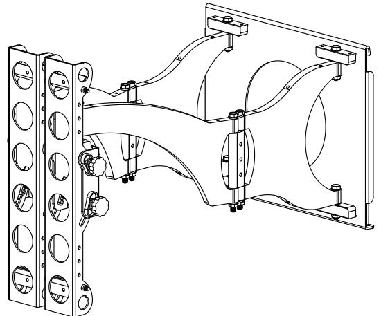
Step 4: Attach the Arm Assembly to the Television (Part I)
First, orient each Vise Assembly (f) so that a 1" Diameter Tube (d) will pass through the 1" round hole in the Monitor Bracket (e) and then between the jaws of the Vise Assembly as shown in Diagram 4a. Insert a 1" Diameter Tube through the top hole in the first Monitor Bracket also shown in Diagram 4a. Repeat this step for the Bottom hole in the same Monitor Bracket.
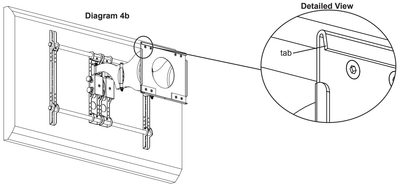
Step 4: Attach the Arm Assembly to the Television (Part II)
Warning: The 1” Diameter Tubes must extend beyond the outside edges of both Monitor Brackets and the Allen Bolts in all 4 Vise Assemblies in the Monitor Brackets and the 4 Vise Assemblies in the Arm Assembly must be tightened for the installation to be safe!
Position the Arm Assembly (b) so that the hook shaped tab shown in the Detailed View of Diagram 4b is on the top. Line up the two 1” diameter holes in the Monitor Bracket (e) at the other end of the Arm Assembly with the with the 1” Diameter Tubes (d). Continue to push the 1” Diameter Tubes through both the vise assemblies on the Arm Assembly and then through the other Monitor Bracket. Again, make sure the Vise Assemblies (f) on both the Arm Assembly and the second Monitor Bracket are oriented so that the 1” Diameter Tubes will pass between the jaws. Once the 1” Diameter Tubes are in place, tighten the allen bolts on the four Vise Assemblies in the two Monitor Brackets with the Allen Key (l) to lock the television to the mount. Next, slide the Arm Assembly into the desired position between the two Monitor Brackets and tighten the four remaining Allen Bolts in the Vise Assemblies inside the Arm Assembly. See Diagram 4b below.
Note: Sanus recommends Arm Assembly to be centered between Monitor Brackets
Step 5: Attach the Wall Plate: Wood Stud installations only.
Warning: DO NOT OVERTIGHTEN THE LAG BOLTS! Tighten Lag Bolts (i) only until the Lag Bolt Washer (j) is pulled firmly against the Wall Plate (a).
The Wall Plate (a) must be mounted to two wood studs at least 12" apart. Use a high quality stud sensor to locate two adjacent studs. It is a good idea to verify where the studs are located with an awl or thin nail. Pre-drill a 2.5" deep hole in each stud at the desired height using a 3/16" drill bit. Make sure these holes are in the center area of the studs and level with each other. Use the Wall Plate as a template to mark the location of the second hole in each stud. Drill 2.5" deep holes using the 3/16" drill bit in the marked locations. Attach the Wall Plate to the wall using four Lag Bolts (i) and four Lag Bolt Washers (j). Make sure the Wall Plate is oriented so the flat surface in the center of the plate is against the wall. See Diagram 5 below.
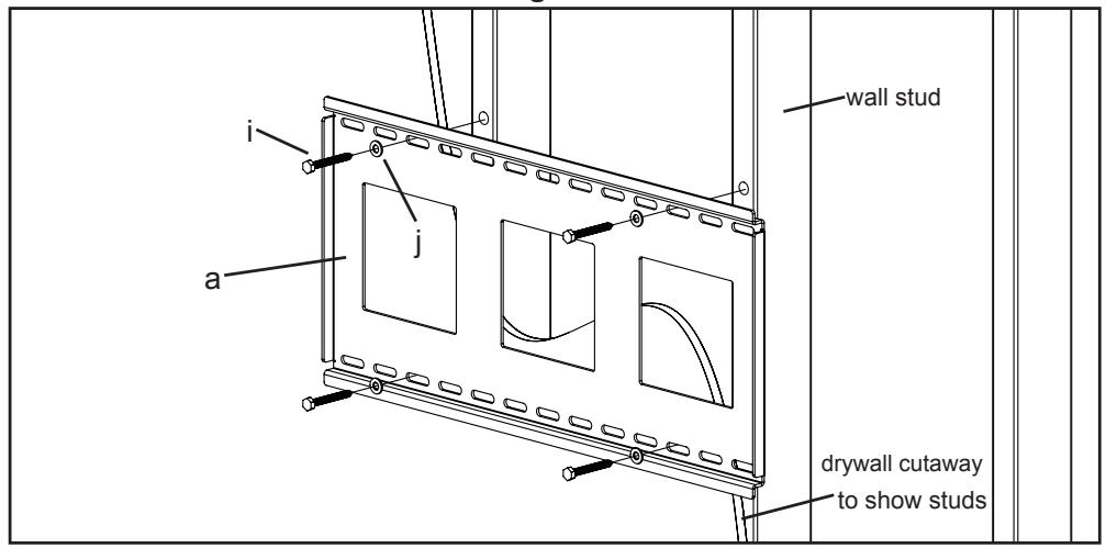
Diagram 5
Step 6: Hang the assembly onto the Wall Plate
Warning: This step may require 2 people to lift the assembly onto the Wall Plate! Sanus is not responsible for injury or damage.
Orient the Arm Assembly (b) so that the arm extends directly away from the television and the transfer plate is parallel with the television. Some televisions may require 2 people to lift! Lift up the assembly and hook the transfer plate onto the tab on the top of the Wall Plate (a) as shown in Diagram 6a. Horizontally adjust the transfer plate side to side on the Wall Plate until it is in the desired location. Thread each Safety Bolt (n) into one of the three holes in the bottom of the transfer plate and tighten them so that they are behind the tab on the bottom of the Wall plate as shown in Diagram 6b.
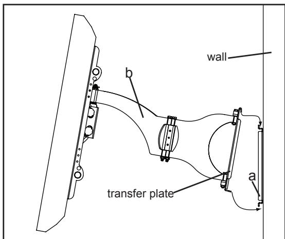
Diagram 6a
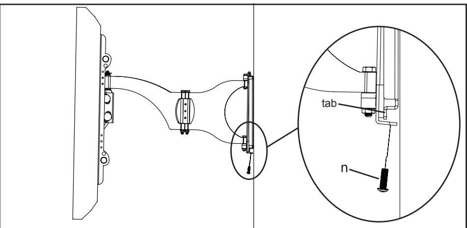
Diagram 6b
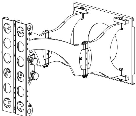
Step 7: Leveling the Monitor and Adjusting the Tension
WARNING: Do NOT REMOVE the tension nuts in Diagram 7!
Once the television is mounted onto the Wall Plate (a), and the Safety Bolts (n) are tight, it can be adjusted to level. Slightly loosen the two allen bolts on the back of the Arm Assembly (b). Once those two bolts are loosened, the television can be adjusted ± 6^ until level. When the television is level retighten the two allen bolts. The tilt can be adjusted by simply tilting the TV. To adjust the tension of tilt, use the tension knobs. The tension nuts labeled in Diagram 7 can be slightly loosened or tightened to adjust the tension of the Arm Assembly. If you need to adjust the tension nut closest to the TV, you must remove the safety bracket, adjust the tension and re-install the safety bracket as shown in the safety bracket installation view of Diagram 7.
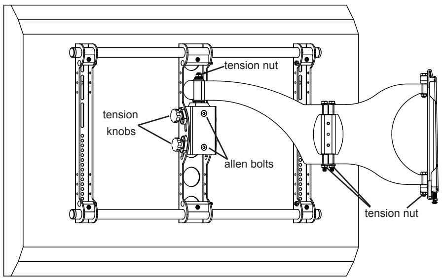
Diagram 7
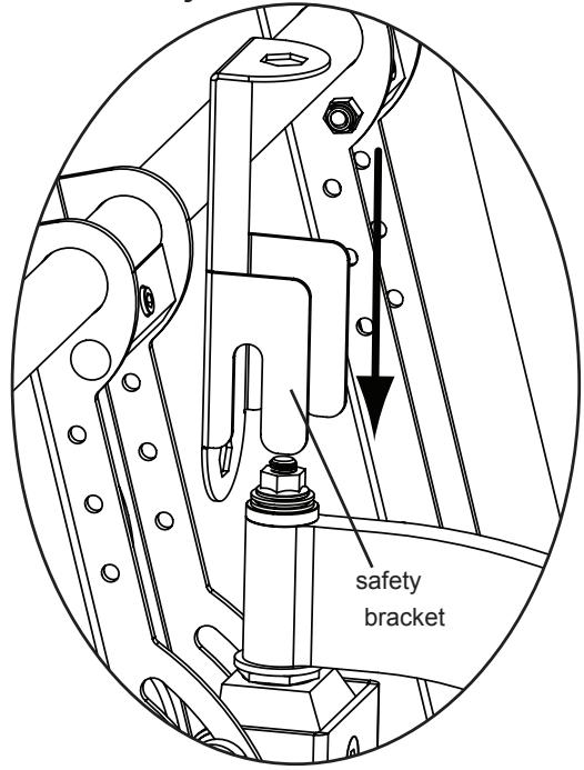
Safety Bracket Installation
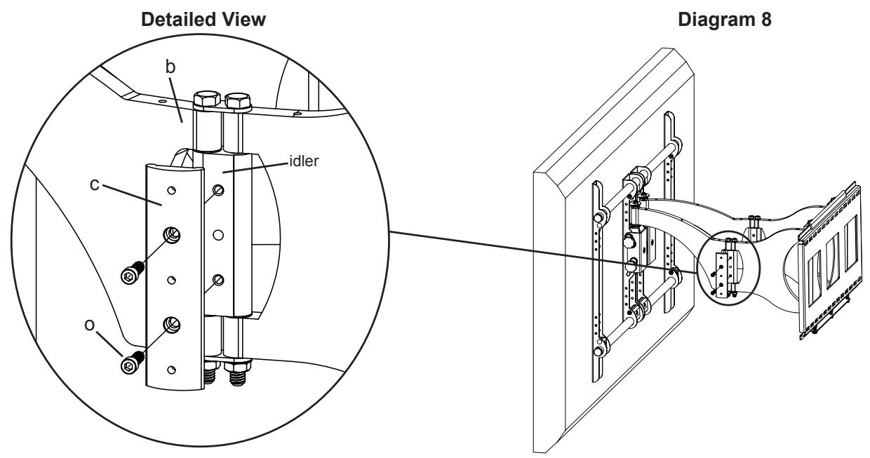
Step 8: Add Preventor
Warning: Watch for Pinch Points. Do not put your hands or fingers between moveable parts!
Position the Preventor so the flat side is facing the idler as shown in the Detailed View of Diagram 8. To attach the Preventor, place a Preventor Bolt (o) through the Preventor and into the holes in the idler. Proceed to tighten the Preventor Bolts with an Allen Key (k) until tight.
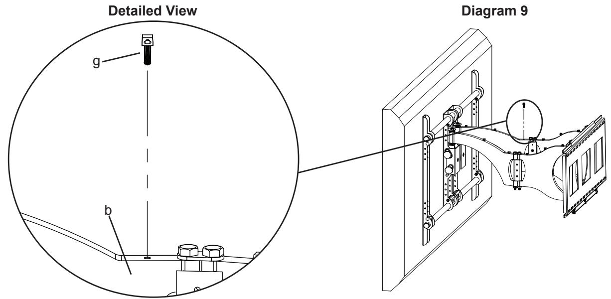
Step 9: Wire Management
Warning: Do not run Cables through a pinch point!
Before beginning cable management pull the television into the position as far from the wall as possible. Leave some slack in the cables so that during motion so there is no added tension on the connectors. There are several places to attach Wire management ties to keep cables out of the way. Wire Tie Clips (g) can be attached to the holes in the top and the bottom of the Arm Assembly (b), sides of the Preventor (c) and the top and bottom of the pillow block by simply pressing them into place as shown in the Detailed View of Diagram 9. Wire Ties (h) can then be added to both the Wire Tie Clips, or the holes in the sides of either of the Monitor Brackets (e).
Sanus Systems 2221 Hwy 36 West. St. Paul, MN 55113 6901-300015<00>
Customer Service: 800.359.5520. See complementary Sanus products at www.sanus.com
SANUS SYSTEMS
(1) Plaque murale - a
(1) Bras - b
(1) Butée - c
(4) - f^