T152-S - Speaker AUDIO DESIGN - Free user manual and instructions
Find the device manual for free T152-S AUDIO DESIGN in PDF.
Download the instructions for your Speaker in PDF format for free! Find your manual T152-S - AUDIO DESIGN and take your electronic device back in hand. On this page are published all the documents necessary for the use of your device. T152-S by AUDIO DESIGN.
USER MANUAL T152-S AUDIO DESIGN
This warranty covers only the original purchaser of Rockford product purchased from an Authorized Rockford Fosgate Dealer in the United States. In order to receive service, the purchaser must provide Rockford with a copy of the receipt stating the customer name, dealer name, product purchased and date of purchase. Products found to be defective during the warranty period will be repaired or replaced (with a product deemed to be equivalent) at Rockford's discretion.
What is Not Covered
I. Damage caused by accident, abuse, improper operations, water, theft, shipping
2.Any cost or expense related to the removal or reinstallation of product
3. Service performed by anyone other than Rockford or an Authorized Rockford Fosgate Service Center
4.Any product which has had the serial number defaced, altered, or removed
5. Subsequent damage to other components
6.Any product purchased outside the U.S.
7.Any product not purchased from an Authorized Rockford Fosgate Dealer
Limit on Implied Warranties
Any implied warranties including warranties of fitness for use and merchantability are limited in duration to the period of the express warranty set forth above. Some states do not allow limitations on the length of an implied warranty, so this limitation may not apply. No person is authorized to assume for Rockford Fosgate any other liability in connection with the sale of the product.
How to Obtain Service
Contact the Authorized Rockford Fosgate Dealer you purchased this product from. If you need further assistance, call 1-800-669-9899 for Rockford Customer Service.You must obtain an RA# (Return Authorization number) to return any product to Rockford Fosgate.You are responsible for shipment of product to Rockford.
EU Warranty
This product meets the current EU warranty requirements, see your Authorized dealer for details.
Rockford Fosgate
Rockford Corporation
600 South Rockford Drive
Tempe,Arizona 85281 U.S.A. In U.S.A., (480) 967-3565 - Customer Service I-800-669-9899
www.rockfordfosgate.com
Designed and Engineered by Rockford Fosgate, Tempe, AZ. USA.
© 2009 Rockford Corporation. All rights reserved.
Rockford Fosgate and the Rockford Fosgate logo are eitherregistered trademarks or trademarks of Rockford Corporation
05/2009 E.R.
1230-55855-01
Installation et fonctionnement
Instalación y funciona
Einbau und Betrieb
Installazione e funzionamento
Date of Purchase:
Serial Number:
Printed in China

CAUTION: Before installation, disconnect the battery negative (-) terminal to prevent damage to the unit, fire and/or possible injury.
PRACTICE SAFE SOUND™
Continuous exposure to sound pressure levels over 100dB may cause permanent hearing loss. High powered auto sound systems may produce sound pressure levels well over 130dB. Use common sense and practice safe sound.
CARTON CONTENTS
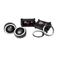
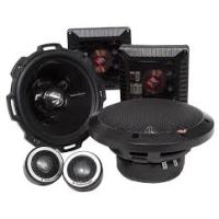
(1) Set T1 Series Speakers with Tweeters and 2-Way Crossover or (1) Set T1 Series Tweeters with HP Crossover
(1) Set of grilles/trim rings
(2) Sets of tweeteter trim rings:
(1 set of polished aluminum)
(1 set of brushed aluminum)
- Tweeter Mounting Hardware with Surface, Angle, and Flush Mounts
- (I) Set Adapter Plates: T152-S (5''x7''/6''x9'') , T162-S (5''x7''/6''x9'')
INSTALLATION CONSIDERATIONS
Before beginning any installation, follow these simple rules:
- Be sure to carefully read and understand the instructions before attempting to install these speakers.
- For safety, disconnect the negative lead from the battery prior to beginning the installation.
- For easier assembly, we suggest you run all wires prior to mounting your speakers in place.
- Use high quality connectors for a reliable installation and to minimize signal or power loss.
- Think before you drill! Be careful not to cut or drill into gas tanks, fuel lines, brake or hydraulic lines, vacuum lines or electrical wiring when working on any vehicle. If installation in a boat, take care not to cut or drill through the main hull.
- Never run wires underneath the vehicle. Running the wires inside the vehicle or hull area provides the best protection.
- Avoid running wires over or through sharp edges. Use rubber or plastic grommets to protect any wires routed through metal, especially the firewall.
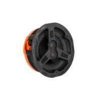
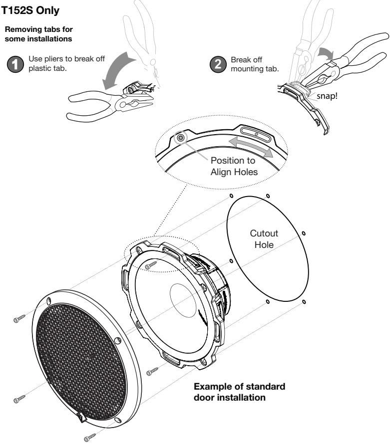
MOUNTING
- Determine where the speakers will be mounted. Ensure an area large enough for the speaker to mount evenly. Be sure that the mounting location is deep enough for the speaker to fit; if mounting in a door, operate all functions (windows, locks, etc.) through their entire operating range to ensure there is no obstruction.
- Refer to the specification chart to determine the proper diameter hole to cut for your speaker model. The template provided also gives the proper cutout size.
- Mark the locations for the mounting screws. Drill the holes with a 1/8 bit.
- Feed the speaker wires through the cutout and connect to the speaker terminals. Be sure to observe proper polarity when connecting the wires. The speaker's positive terminal is indicated with a "+"
- On models with slotted holes, fit the speaker into the cutout and install the screws in the slots at the top and bottom. This will allow you to rotate the speaker to match the remaining mounting holes. When aligned, tighten the screws.
- Tighten the screws until the speaker is snug in place to prevent rattling. Do not over tighten the screws.
NOTE: If needed, use the adapter plate provided to mount the speaker. See Adapter Plate Templates at the end of this manual.
Example of Discreet Dual Clamp (DDC™)
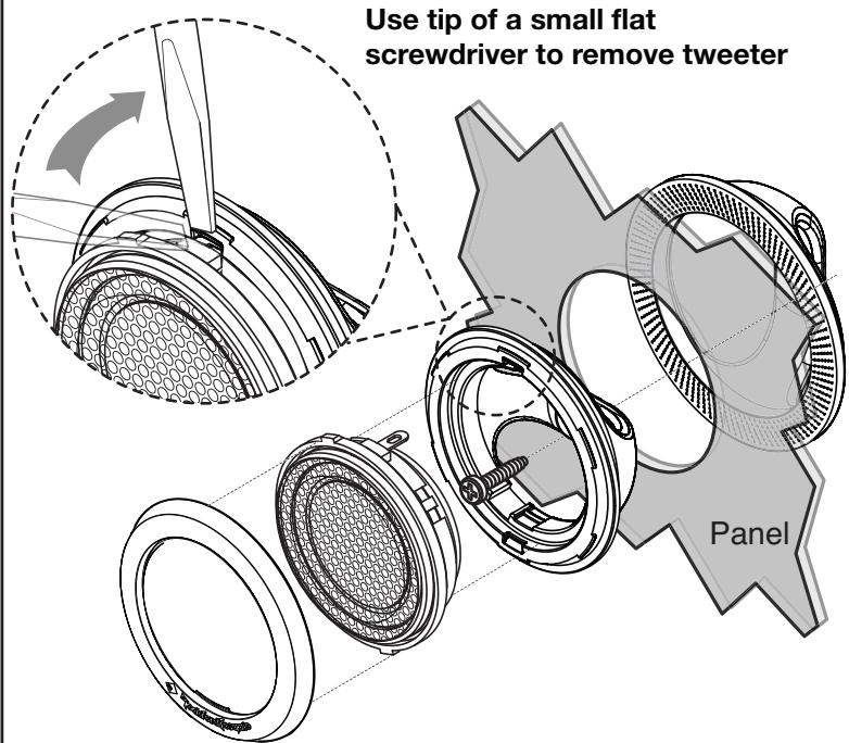
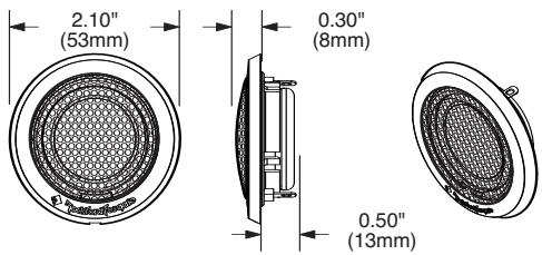
Tweeter Mounting (Flush Mount)
FEATURES
Discreet Dual Clamp (DDC™) Tweeter Mount
Every aspect of the new Tweeter design has been completely re-engineered to allow for maximum ease of installation and fitment. This optimized patent pending design provides concentric clamping pressure around the perimeter of the mounting hole.
The "mounting cups" are in fact not "cups" at all, but rather unobtrusive "clamps" that quickly and easily mount in a standard 1.75 inch (45mm) hole saw opening with a single center screw securing with balanced pressure to both faces of the mounting surface. From there, the tweeter simply snaps into place and is secured by a snap-on trim ring. Removal is easy if needed. The protective grille on the tweeter is non-removable and an integral part of the design.
WIRING
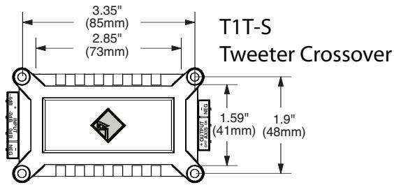
T1T-S Crossover Wiring
I. Use illustration for proper connection.
2. Be sure to maintain speaker polarity.
3. Connecting the positive wire to 0dB matches the amplitude of the tweeter to the mid-range (woofer).
4. Connecting positive wire to -2dB or -4dB to reduce the amplitude of the tweeter -2dB or -4dB lower than the mid-range, (ideal for tweeters located high in door panels and mid-range low in the kick panel).
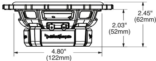
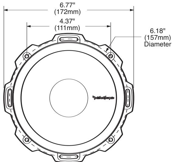
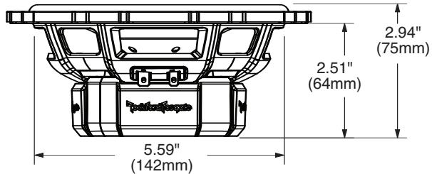
SPECIFICATIONS
| T1 Components | T152-S | T1652-S | T1T-S |
| Nominal Diameter - inch (mm) | 5.25 (133) | 6.5 (165) | 1.0 (25.4) |
| Description | Component System | Component System | Tweeter System |
| Nominal Impedance (ohms) | 4Ω | 4Ω | 4Ω |
| Frequency Response (Hz) | 65Hz - 20kHz | 55Hz - 22kHz | 3kHz - 22kHz |
| Crossover Frequency (Hz) | 3.5kHz | 3kHz | 3kHz |
| High-Pass Butterworth Crossover | 18dB/octave | 18dB/octave | 18dB/octave |
| Low Pass Butterworth Crossover | 12dB/octave | 12dB/octave | - |
| Voice Coil Diameter - inch (mm) | 1.1 (28) | 1.2 (31) | 1.0 (25.4) |
| Fs - Free Air Resonance (Hz) | 65 | 55 | 1.8kHz |
| Qts | 0.60 | 0.50 | - |
| Vas - cu. ft. (Liter) | 0.34 (9.6) | 0.56 (16) | - |
| Xmax - inch (mm) | 0.16 (4.0) | 0.24 (6.0) | - |
| SPL (dB @ 1w/1m) | 87 dB | 89 dB | 90 dB |
| Power Handling-Watts (RMS / Peak) | 75 / 150 | 100 / 200 | 75 / 150 |
| Rec. Amp Power-Watts (RMS) | 22.5W ~ 75W | 30W ~ 100W | 22.5W ~ 75W |
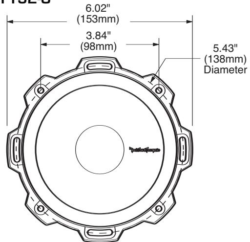
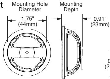
| Mounting Diameter-inch (mm) | 4.80 (122) | 5.59 (142) | 1.75 (45) (Flush Mount) |
| Mounting Depth-inch (mm) | 2.03 (52) | 2.51 (64) | 0.95 (24) (Flush Mount) |
| Includes Grille/Trim Ring | YES | YES | YES |
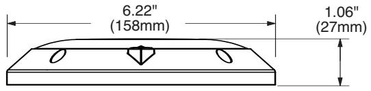
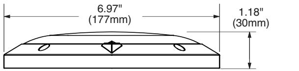
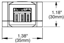
| Trim Ring Diameter-inch (mm) | 6.22 (158) | 6.949 (177) | 2.13 (54) |
| Trim Ring Height-inch (mm) | 1.06 (27) | 1.18 (30) | 0.31 (8) |
| Includes Adapter Plate | 5"x7"/6"x9" | 5"x7"/6"x9" | NO |
See figures on following pages.
Specifications subject to change without notice.
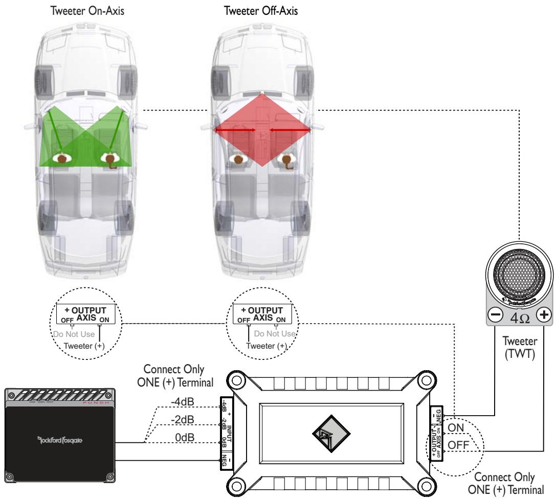
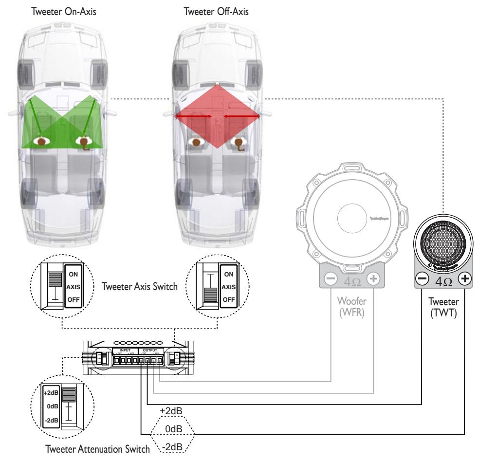
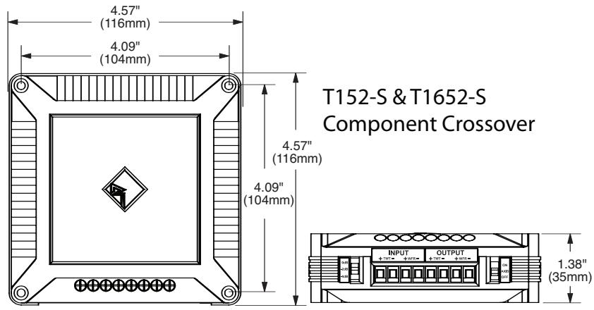
T152-S & T1652-S Component Wiring
I. Use illustration for proper connection.
2. Be sure to maintain speaker polarity.
Axis ON-OFF Switch
I. Set to ON or OFF to match position of tweeter relative to listener. Default OFF position satisfies most installations.
dB Switch
I. 0dB matches the amplitude (no increase/no attenuation) of the tweeter to the same level as the mid-range (woofer).
2. +2dB increases and -2dB reduces the amplitude of tweeter in relation to the mid-range, (ideal when matching offset installation like tweeters located high in door panels and midranges low in kick panels).
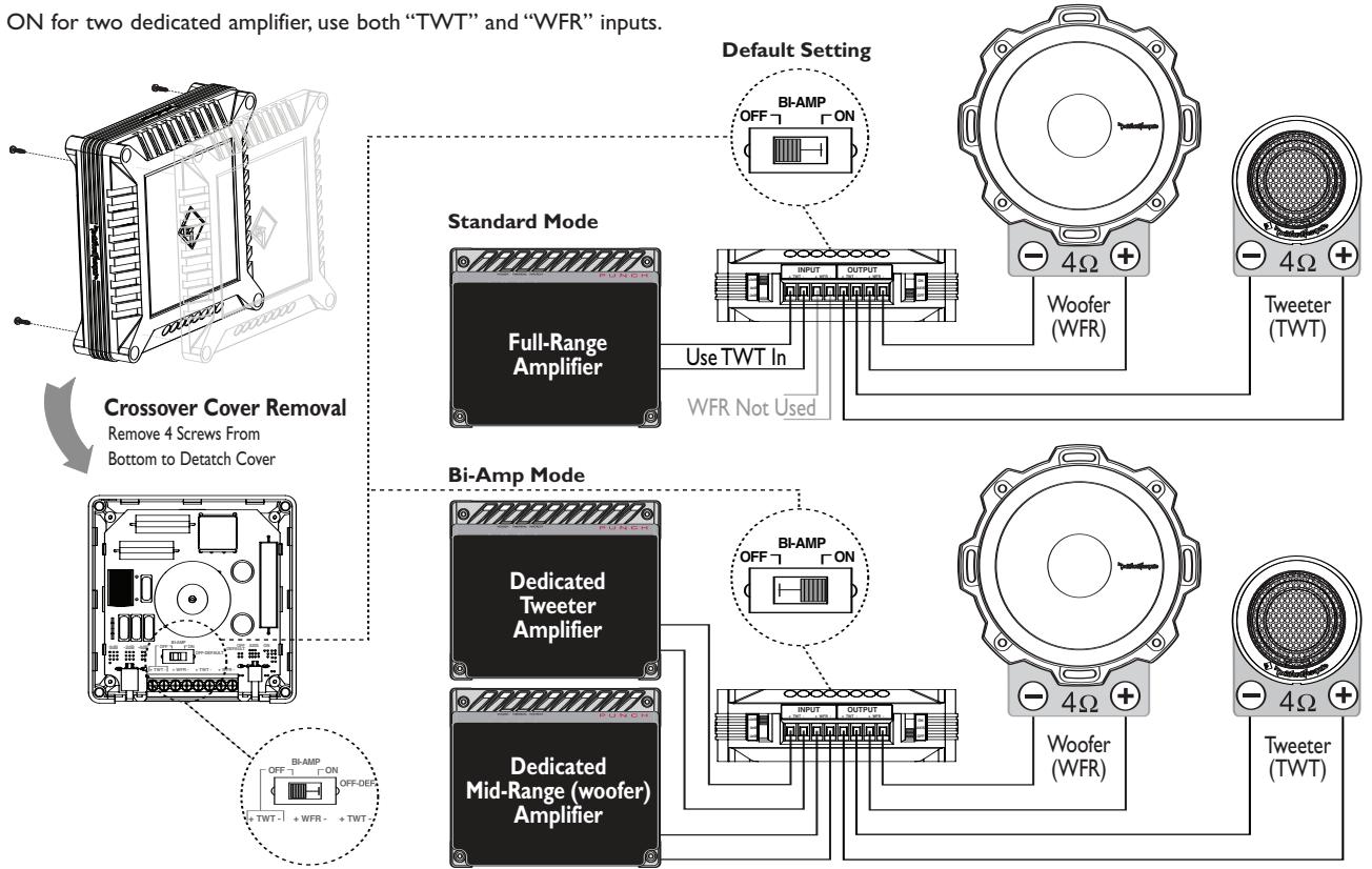
T152-S & T1652-S Bi-Amp Crossover Wiring
I. Use illustration for proper connection and be sure to maintain speaker polarity.
2. Remove 4 screws from crossover bottom to detatch cover.
3. When BI-AMP switched OFF for one amplifier, use only "TWT" input.
4. When Bl-AMP switched ON for two dedicated amplifier, use both "TWT" and "WFR" inputs.
SPECIFICATIONS
T152-S
T1652-S
Tweeter
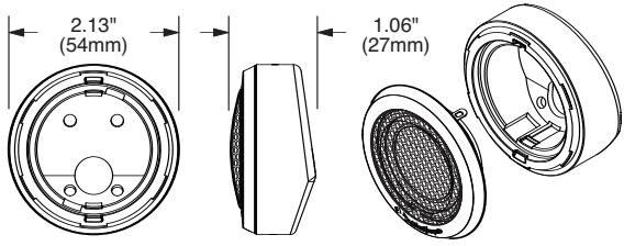
Surface Mount
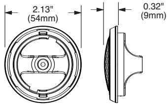
Flush Mount
Français
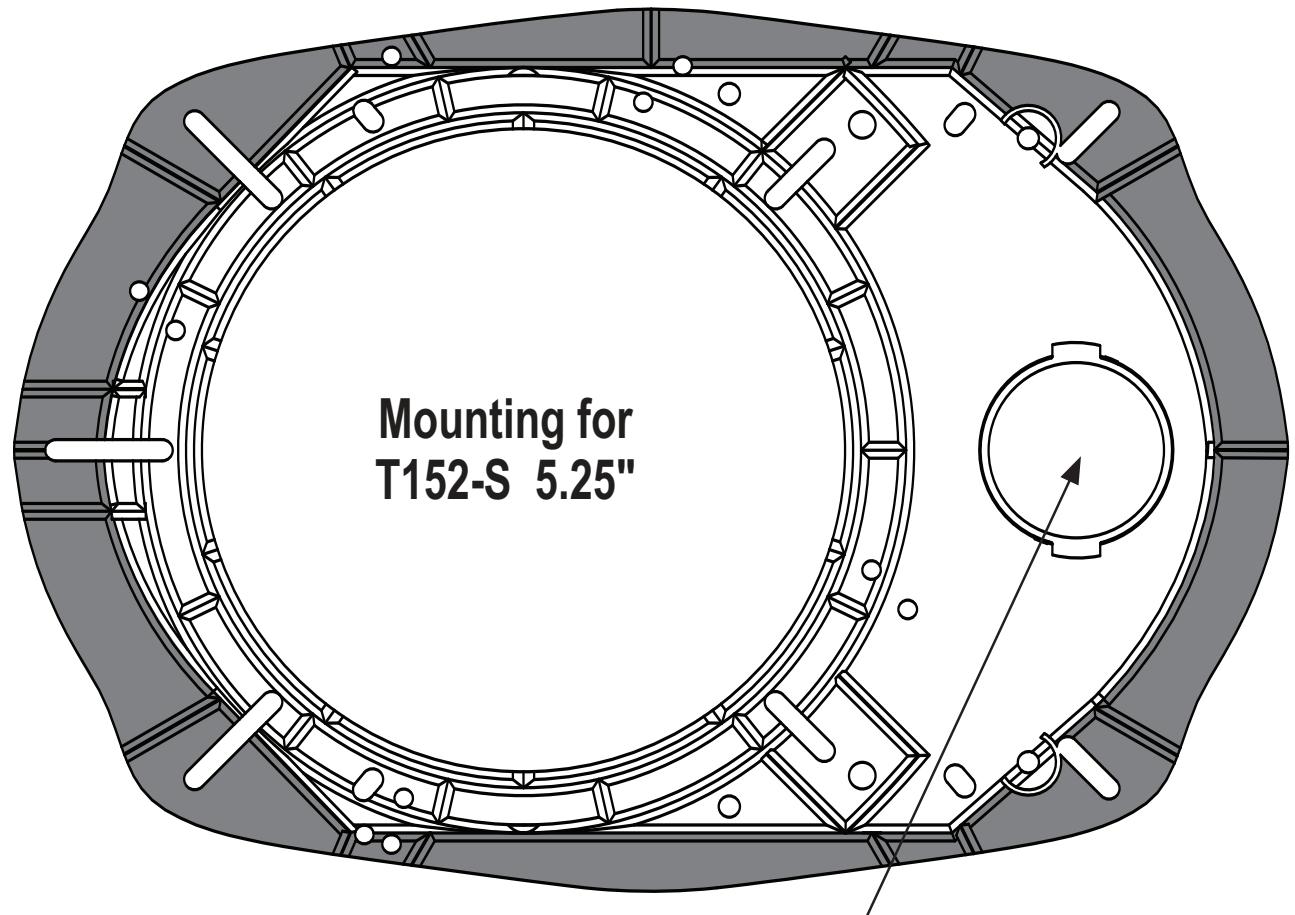
Adapter Plate Template – 6"x9" Hole Mounting For 5"x7" Hole Mounting - Remove Dark Shaded Areas
Remove For Tweeter
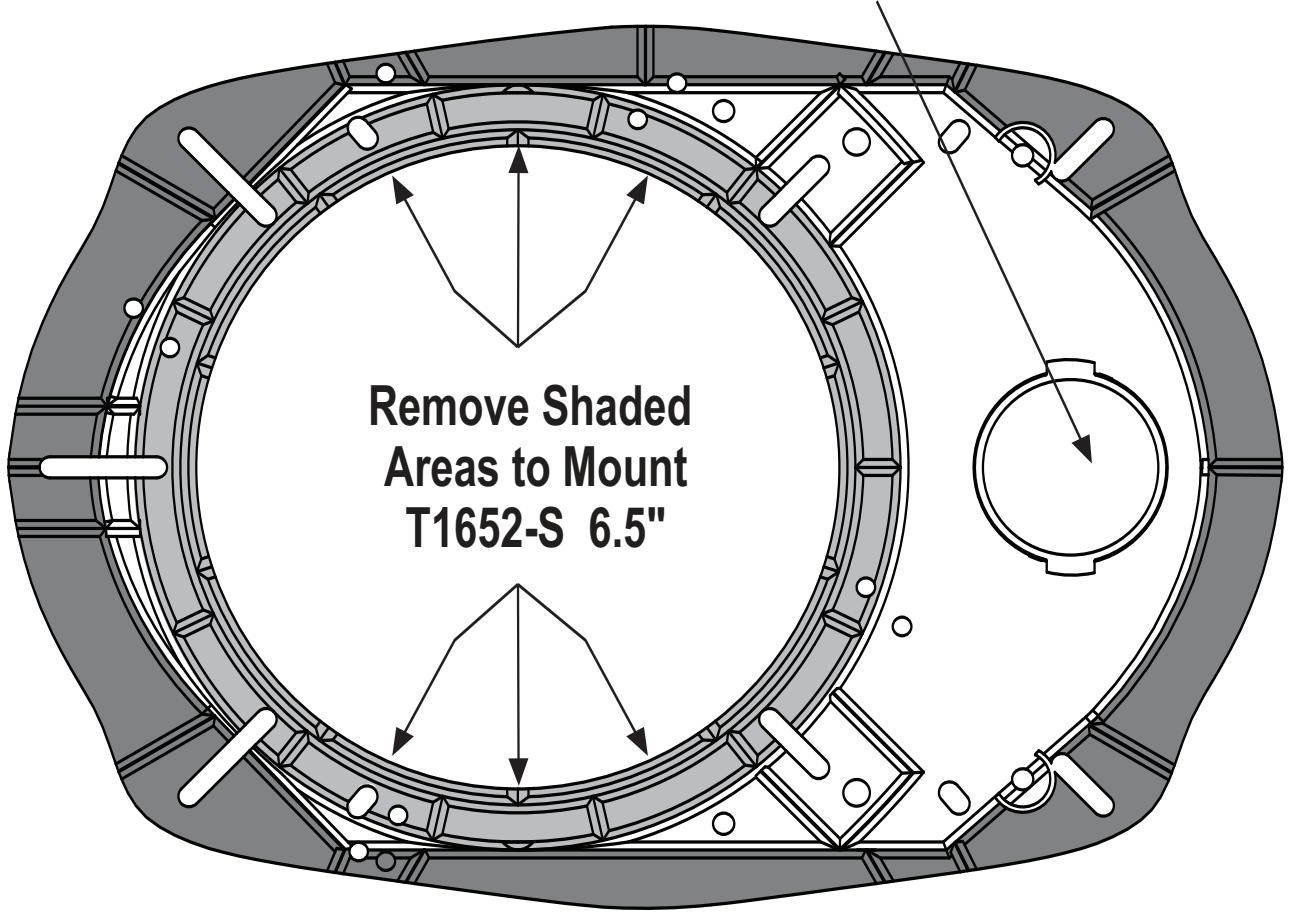
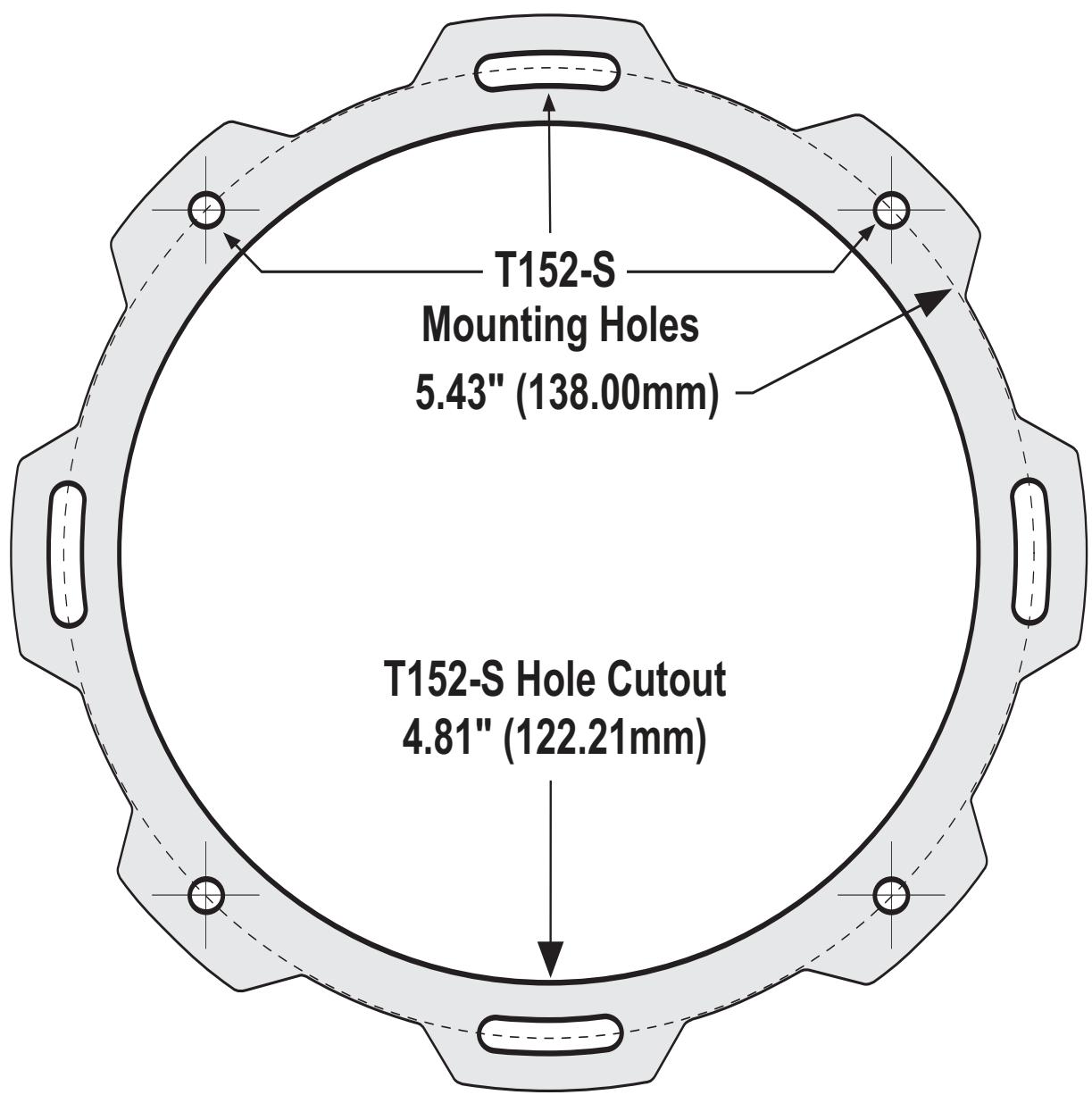
Mounting Template
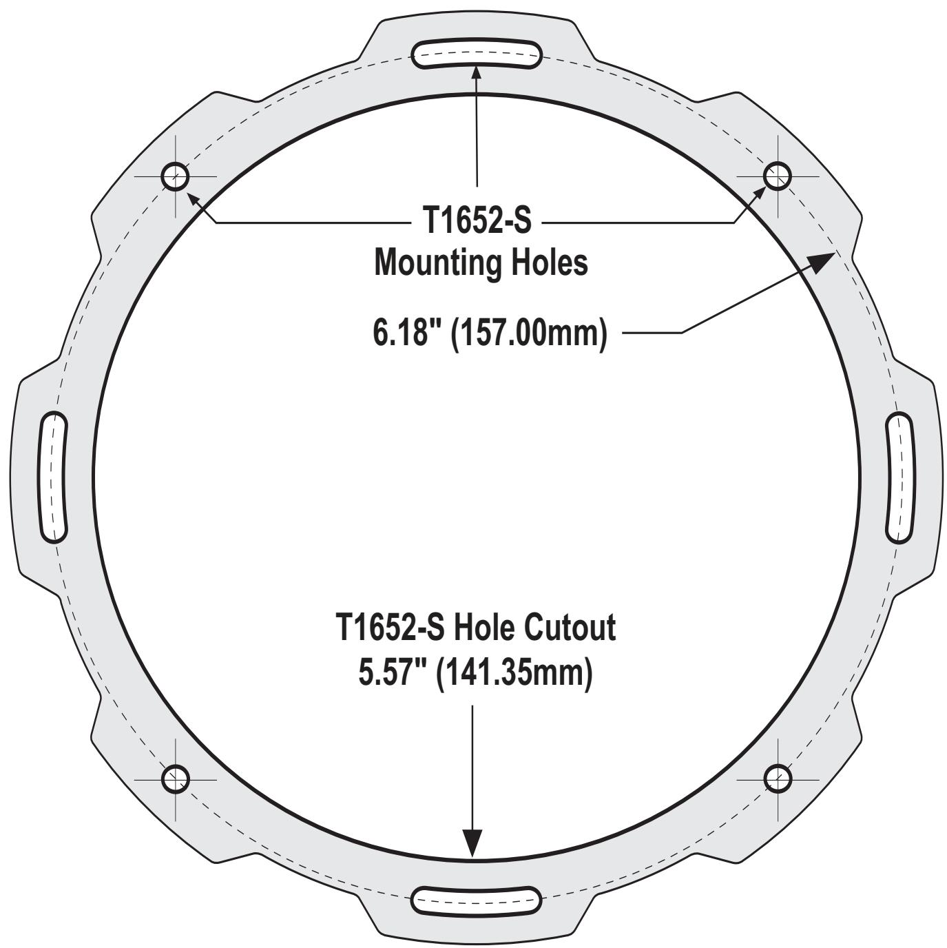
Mounting Template