
STDX24000N - Magnetic Tape Reader QUANTUM - Free user manual and instructions
Find the device manual for free STDX24000N QUANTUM in PDF.
| Product Type | Magnetic Tape Drive |
| Brand | QUANTUM |
| Model | STDX24000N |
| Cartridge Format | LTO Ultrium (Generation 6) |
| Native Capacity | 6.25 TB |
| Compressed Capacity | Up to 15 TB (2.5:1) |
| Interface | SAS 6 Gb/s |
| Native Transfer Speed | 400 MB/s |
| Compressed Transfer Speed | Up to 1,000 MB/s |
| Dimensions (W x D x H) | 146 x 210 x 42 mm (half-height) |
| Weight | 1.2 kg |
| Power Supply | 5 V / 12 V DC via internal connector |
| Power Consumption | 12 W operating, 6 W standby |
| Main Functions | Read and write LTO-6 tapes and backward compatible with LTO-5 and LTO-4 |
| Hardware Encryption | 256-bit AES |
| Maintenance and Cleaning | Use an LTO cleaning cartridge every 50 uses or in case of error |
| Safety | Compliant with FCC Class B, CE, RoHS; protection against overvoltage and electrostatic discharge |
| Spare Parts and Repairability | Replacement cartridges, SAS cables, mounting kit; repair by authorized center |
| Warranty | 3 years manufacturer (according to general conditions) |
| Operating Temperature | 10 °C to 40 °C |
| Relative Humidity | 20% to 80% (non-condensing) |
| Certifications | UL, TUV, VCCI, BSMI |
Frequently Asked Questions - STDX24000N QUANTUM
User questions about STDX24000N QUANTUM
0 question about this device. Answer the ones you know or ask your own.
Ask a new question about this device
Download the instructions for your Magnetic Tape Reader in PDF format for free! Find your manual STDX24000N - QUANTUM and take your electronic device back in hand. On this page are published all the documents necessary for the use of your device. STDX24000N by QUANTUM.
USER MANUAL STDX24000N QUANTUM
Copyright and Trademarks
Copyright © 2004 by Certance LLC. All Rights Reserved.
Part Number 50001756
April 2004
Certance and the Certance logo are trademarks of Certance LLC. Other product names are trademarks or registered trademarks of their respective owners.
Certance reserves the right to change, without notice, product offerings or specifications. No part of this publication may be reproduced in any form without written permission from Certance LLC.
Certance provides this manual "as is," without warranty of any kind, either expressed or implied, including, but not limited to, the implied warranties of merchantability and fitness for a particular purpose. Certance reserves the right to change, without notification, the specifications contained in this manual.
Certance assumes no responsibility for the accuracy, completeness, sufficiency, or usefulness of this manual, nor for any problem that might arise from the use of the information in this manual.
Warnings
All safety and operating instructions should be read before this product is operated, and should be retained for future reference. This unit has been engineered and manufactured to assure your personal safety. Improper use can result in potential electrical shock or fire hazards. In order not to defeat the safeguards, observe the following basic rules for installation, use and servicing.

CAUTION: This symbol should alert the user to the presence of "dangerous voltage" inside the product that might cause harm or electric shock.
Caution! Risk of electric shock! Do not open!
To reduce the risk of electric shock, do not remove the cover (or back). No user-serviceable parts are inside. Refer servicing to qualified service personnel.
Heed warnings - All warnings on the product and in the operating instructions should be adhered to.
- Follow instructions — All operating and use instructions should be followed.
- Ventilation — The product should be situated so that its location or position does not interfere with proper ventilation.
- Heat — The product should be situated away from heat sources such as radiators, heat registers, furnaces, or other heat producing appliances.
Power sources — The product should be connected to a power source only of the type directed in this document or as marked on the product.
- Power cord protection — The power cord should be routed so that it is not likely to be walked on or pinched by items placed upon or against it, paying particular attention to the cord at the wall receptacle, and the point where the cord exits from the product.
To complete the disconnection of the electricity, please remove the power (electric) cord and the SCSI cable from their connections in the back of the product. The plugs should be placed near the product for easy access.
- Object and liquid entry — Care should be taken to insure that objects do not fall and liquids are not spilled into the product's enclosure through openings.
Servicing - The user should not attempt to service the product beyond that described in the operating instructions. All other servicing should be referred to qualified service personnel.
Precautions
- Do not use oil, solvents, gasoline, paint thinners, or insecticides on the unit.
- Do not expose the unit to moisture or to temperatures higher than 151^ ( 66^ ) or lower than -40^ ( -40^ ).
- Keep the unit away from direct sunlight, strong magnetic fields, excessive dust, humidity, and electronic/electrical equipment, which generate electrical noise.
- Hold the power cord by the head when removing it from the AC outlet; pulling the cord can damage the internal wires.
Use the unit on a firm level surface free from vibration, and do not place anything on top of the unit.
FCC Notice
This equipment generates and uses radio frequency energy and, if not installed and used properly — that is, in strict accordance with the manufacturer's instructions — may cause interference to radio communications or radio and television reception. It has been tested and found to comply with the limits for a Class B computing device in accordance with the specifications in Part 15 of FCC Rules, which are designed to provide reasonable protection against such interference in a residential installation. However, there is no guarantee that interference will not occur in a particular installation. If this equipment does cause interference to radio or television reception, which can be determined by turning the equipment on and off, you are encouraged to try to correct the interference by one or more of the following measures:
Reorient the receiving antenna.
Relocate the computer with respect to the receiver.
- Move the computer into a different outlet so that the computer and receiver are on different branch circuits.
If necessary, you should consult the dealer or an experienced radio/television technician for additional suggestions. You may find the booklet, How to Identify and Resolve Radio-TV Interference Problems, prepared by the Federal Communications Commission, helpful. This booklet (Stock No. 004-000-00345-4) is available from the U.S. Government Printing Office, Washington, DC 20402.

WARNING: Changes or modifications made to this equipment, which have not been expressly approved by Certance, may cause radio and television interference problems that could void the user's authority to operate the equipment.
Further, this equipment complies with the limits for a Class B digital apparatus in accordance with Canadian Radio Interference Regulations.
The desktop device drive described in this manual requires shielded interface cables to comply with FCC emission limits.

WARNING: To prevent fire or electrical shock hazard, do not expose the unit to rain or moisture.
To avoid electrical shock, do not open the cabinet.
Refer servicing to qualified personnel.
Contents
Chapter 1 - Introduction 9
Chapter 2 - Installation 10
Introduction 10
Unpacking and Inspection 10
Installing an Internal DAT24 Drive 10
Installing the Desktop DAT24 Drive 18
Chapter 3 - Operation 20
Introduction 20
Loading a Cartridge 20
Unloading a Cartridge 21
Initializing a Blank DAT Cartridge 21
DAT Cartridge Compatibility 22
Write-Protecting a DAT Cartridge 22
Cleaning the Tape Heads 23
LED Codes 23
Chapter 4 - UNIX Settings 26
Introduction 26
Setting DIP Switches for UNIX Support 26
Configuring Inquiry Strings 27
Configuring for the DEC UNIX Environment 28
Configuring for the Sun Environment 29
Configuring for the SGI Environment 30
Configuring for the HP-UX Workstation Environment 32
Configuring for the IBM AIX Environment 33
Configuring for the SCO Environment 34
List of Figures
Figure 1. DIP Switches and Jumpers for Internal DAT24 Tape Drives 11
Figure 2. DIP Switch Settings for Internal DAT24 Drives 12
Figure 3. Location of Jumper Blocks on Internal DAT2 Drives. 14
Figure 4. Mounting Holes for Internal DAT24 Drive in a 3.5-inch Configuration (no mounting brackets) 16
Figure 5. Mounting Holes for Internal DAT24 Drive in 5.25-inch Configuration (with mounting brackets) 16
Figure 6. Locations of SCSI Interface and Power Connectors on the Internal Drive .... 17
Figure 7. Rear Panel of the Desktop Drive 19
Figure 8. SCSI Termination Examples 19
Figure 9. Loading a DAT Tape Cartridge (3.5-inch drive) 20
Figure 10. Location of Tape Eject Button and Drive Status LED. 21
Figure 11. Write-protect Tab on a DAT Cartridge 22
Figure 12. Status LEDs on the Front of the Drive 24
List of Tables
Table 1. DAT24 Models Covered in This User's Guide. 9
Table 2. LED Flash Codes 24
Table 3. Cartridge Status LED 25
Table 4. Drive Configuration Settings.. 26
Table 5. Inquiry Strings 27
Table 6. DAT24 PRTNO Value.. 27
1 Introduction
The Certance DAT24 is a digital audio tape (DAT) drive that supports the Digital Data Storage (DDS-3) tape format. The DAT24 drive provides a typical capacity of 24 Gbytes, assuming 2:1 data compression (native capacity is 12 Gbytes).
The DAT24 tape drive can connect to a standard, single-ended SCSI or SCSI-2 interface. You can use a 50-conductor flat cable or a 25-signal twisted-pair cable to connect the drive to a SCSI host adapter. The cable should not exceed 6 meters (19.5 feet).
The DAT24 drive is offered as internal and desktop versions:
- The internal version is available as a 3.5-inch or 5.25-inch tape drive. It provides a 50-pin, dual-row single-ended SCSI connector at the back of the drive.
- The desktop version provides two 50-pin, shielded connectors (ANSI Alternative 2) on the back panel. These connectors consist of two rows of ribbon contacts spaced 2.16 ~mm (0.085 in) apart. Either connector can be used as a SCSI IN or SCSI OUT connection.
Table 1 on page 9 identifies the Certance DAT24 drive models and model numbers covered by this User's Guide.
Table 1. DAT24 Models Covered in This User's Guide
| Model | Model Number |
| 3.5-inch internal model | STD124000N |
| 5.25-inch internal model | STD224000N |
| Desktop model | STD624000N |
2 Installation
Introduction
This chapter explains how to install the internal and desktop DAT24 tape drives.
Topics covered in this chapter are:
"Unpacking and Inspection" on page 10
- "Installing an Internal DAT24 Drive" on page 10
- "Installing the Desktop DAT24 Drive" on page 18
Unpacking and Inspection
Although drives are inspected and carefully packaged at the factory, damage may occur during shipping. Follow these steps for unpacking the drive.
- Visually inspect the shipping containers and notify your carrier immediately of any damage.
- Place shipping containers on a flat, clean, stable surface; then carefully remove the contents. If the equipment is damaged, notify your Certance representative.
- Always save the containers and packing materials for any future reshipment.
Installing an Internal DAT24 Drive
Installing the internal DAT24 drive involves the following steps:
- Observe the guidelines and cautions for handling internal tape drives. See "Internal Tape Drive Guidelines and Cautions" on page 11.
- Configure the drive. See "Configuring the Internal DAT24 Drive" on page 11.
- Mount the drive. See "Mounting an Internal DAT24 Drive" on page 15.
- Connect the power and interface cables. See "Connecting Power and Interface Cables" on page 17.
- Registering the tape drive. After you install the DAT24, register it. Registering it ensures that you will receive the latest information about the drive, as well as other product, service, and support information. For your convenience, you can register the DAT24 through our Web site at http://register.certance.com.

NOTE: Internal drives come in two mounting configurations. Drives configured for 5.25-inch bays are identical to those designed for 3.5-inch bays, except that drive-mounting brackets have been added on each side of the drive. Installation procedures are the same for both drive configurations.
Internal Tape Drive Guidelines and Cautions
The following guidelines and cautions apply to handling and installing the internal DAT24 tape drive. Keep them in mind as you install the internal drive.
- Handle the drive by the sides rather than by the top cover to reduce the risk of dropping the drive or damaging it during installation.
- Internal drives contain some exposed components that are sensitive to static electricity. To reduce the possibility of damage from static discharge, the drives are shipped in a protective antistatic bag. Do not remove the drive from the antistatic bag until you are ready to install it.
- Before you remove the drive from the antistatic bag, touch a metal or grounded surface to discharge any static electricity buildup from your body.
Always lay the drive either on top of the antistatic bag or place it inside of the bag to reduce the chance of damage from static discharge.
Configuring the Internal DAT24 Drive
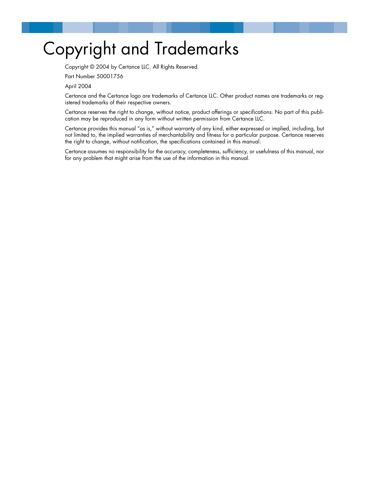
Before you install the internal DAT24 tape drive in your computer, you may need to set the drive's SCSI ID or other drive features. Most features are set using a bank of dip-switches on the underside of the drive (see Figure 1 on page 11). To control SCSI termination and terminator power, or to configure the drive for remote SCSI address selection, use the jumpers on the back of the drive, above the interface and power connectors.
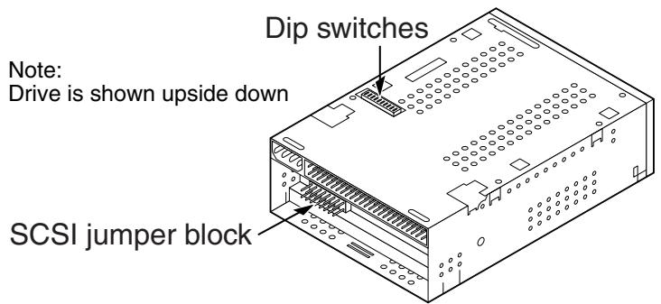
Figure 1. DIP Switches and Jumpers for Internal DAT24 Tape Drives
The default settings for internal DAT24 tape drives are:
SCSI ID is 0.
- Drive reads and writes both MRS and non-MRS 4-mm media.
- Parity checking is disabled.
Data compression is enabled.
Power-on self-test diagnostics are disabled.
SCSI termination is disabled.
If the default settings are appropriate for your computer system, skip ahead to "Mounting an Internal DAT24 Drive" on page 15. Otherwise, proceed to "Changing DIP Switch Settings" on page 12.
Changing DIP Switch Settings
Figure 2 on page 12 shows the location of DIP switches on the underside of the internal DAT24 drive. Factory-default settings for each switch are also shown in Figure 2 on page 12. These settings are described in detail on the following pages.
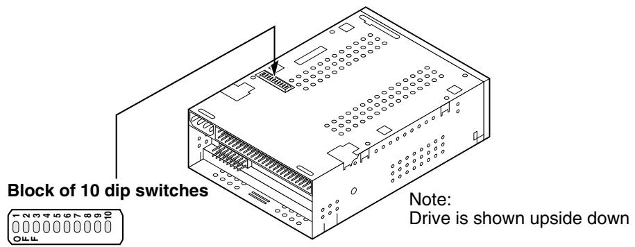
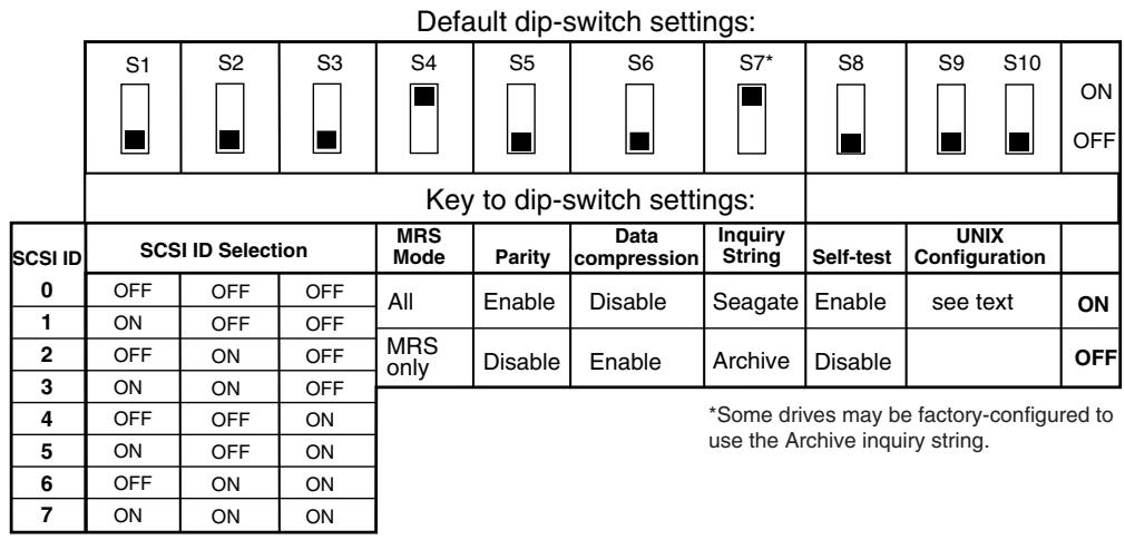

Figure 2. DIP Switch Settings for Internal DAT24 Drives
NOTE: If you change a DIP switch setting, the new setting does not take effect until you restart the drive or send a SCSI Bus Reset to the drive.
SCSI ID Switches (Switches 1 through 3)
Switches 1, 2, and 3 correspond to the SCSI device address identification bits 0 (least-significant bit), 1, and 2 (most-significant bit), respectively. The default setting is SCSI ID 0 (all three switches OFF).

NOTE: Each SCSI device on a bus must have a unique SCSI ID. The SCSI host controller generally uses ID 7. In some systems, the boot drive uses ID 0.
Media Recognition System (Switch 4)
- Switch 4 ON = Media Recognition System mode disabled (default)
- Switch 4 OFF = Media Recognition System mode enabled
The media-recognition system allows the drive to determine whether a DAT tape supports the DDS standard. Using non-DDS media may appear to give satisfactory results, but the inferior specifications of such media can cause data-integrity problems.
Switch 4 enables or disables Media Recognition System (MRS) mode. If switch 4 is ON (the default setting), the drive reads or writes both MRS and non-MRS 4-mm media. If switch 4 is OFF, the drive reads and writes to MRS media, and reads from but does not write to 4-mm media.
Parity Check (Switch 5)
- Switch 5 ON = Parity checking enabled
- Switch 5 OFF = Parity checking disabled (default)
Switch 5 enables or disables parity checking for the SCSI bus. If switch 5 is ON, parity checking is enabled. If switch 5 is OFF (the default setting) parity checking is disabled, but parity is still generated by the drive.
DDS Pass-through Mode (Switch 6)
- Switch 6 ON = DDS pass-through data compression disabled
- Switch 6 OFF = DDS pass-through data compression enabled (default)
If switch 6 is OFF (the default setting), DDS pass-through data compression is enabled. If switch 6 is ON, data compression is disabled.

NOTE: The setting of switch 6 can be overridden if the host computer issues the appropriate SCSI Mode Select command.
Inquiry String (Switch 7)
- Switch 7 ON = Drive identifies itself as a Seagate DAT drive (default)
- Switch 7 OFF = Drive identifies itself as an Archive Python drive
If switch 7 is ON, the drive generates a SCSI inquiry string that identifies it as a Seagate DAT drive. For compatibility with older software and operating systems, the drive can be configured as an Archive Python drive by setting switch 7 to OFF.
Power On Self Test (Switch 8)
- Switch 8 ON = Drive performs Power On Self Test
- Switch 8 OFF = Drive does not perform Power On Self Test (default)
Switch 8 enables or disables execution of Power On Self Test (POST) diagnostics when powered on. If switch 8 is OFF (the default setting), the drive does not perform a POST. If switch 8 is ON, the drive responds to SCSI commands only after successful completion of the POST (about 5 seconds).
UNIX Operating Systems (Switches 9 and 10)
Switches 9 and 10 configure the DAT24 tape drive for use with UNIX operating systems. For more information, see Chapter 4, "UNIX Settings" on page 26.
Jumper Settings
Configuration jumpers on the back of the drive control SCSI bus termination and terminator power. The jumpers can also be used for remote SCSI address selection. Figure 3 on page 14 shows the locations of the jumper block and jumper settings for the internal DAT drive.
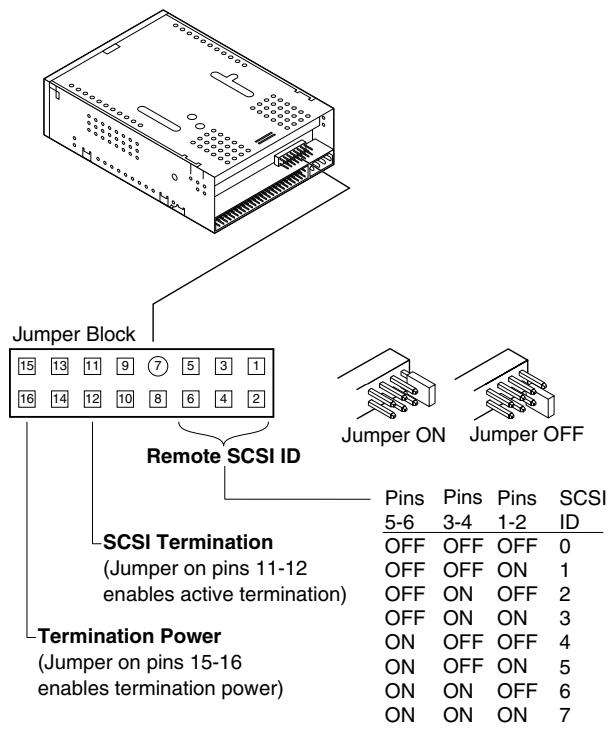
Figure 3. Location of Jumper Blocks on Internal DAT2 Drives
Settings for each jumper described in detail in the following pages. The default settings are:
Terminator power is disabled.
Active termination is disabled.
Enabling SCSI Termination
Active SCSI termination is disabled as the factory default. If the drive is the only device on the SCSI bus, or if it is the last device on the bus, enable active termination by placing a jumper across pins 11 and 12.
Terminator Power
You can enable terminator power if needed for terminators or other SCSI devices through a jumper placement. The factory default for internal drives is that terminator power is disabled. To enable terminator power, place a jumper across pins 15 and 16, as shown in Figure 3 on page 14.

Caution. If the jumper is installed, be careful not to short the TERMPWR signal to ground.
The drive contains a terminator power fuse to prevent damage to drive components in case the terminator power is shorted. If terminator power is enabled and the SCSI cable is connected upside down, for example, this fuse may blow to prevent damage to the drive. If this occurs, the drive will no longer supply terminator power to the bus. To replace the fuse, return the drive to an authorized repair facility.
Remote SCSI Address Selection
Use pins 1 through 6 to select the SCSI address remotely. To do so, connect a remote SCSI ID switch to pins 1 through 6.
- Pins 1 and 2 configure SCSI ID bit 0.
- Pins 3 and 4 configure SCSI ID bit 1.
- Pins 5 and 6 configure SCSI ID bit 2.

NOTE: If you use remote SCSI ID selection, set switches 1 through 3 to the OFF position (see Figure 1 on page 11).
Mounting an Internal DAT24 Drive
You can install the internal DAT24 drive horizontally or vertically (on its side).
Mounting the Drive in a 3.5-inch Drive Bay
To mount the drive in a 3.5-inch drive bay, mount the drive using two M3.0 metric screws on each side of the drive. Do not use screws longer than 4mm or you may damage the drive. The 3.5-inch drive has four screw holes on the bottom and five on each side (see Figure 4 on page 16).
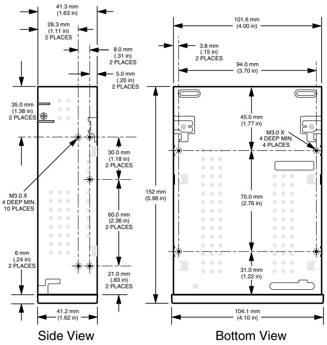
Figure 4. Mounting Holes for Internal DAT24 Drive in a 3.5-inch Configuration (no mounting brackets)
Mounting the Drive in a 5.25-inch Drive Bay
To mount the drive in a 5.25-inch drive bay, use a drive with mounting brackets. The 5.25-inch drive brackets have four screw holes on the bottom and six on each side (see Figure 5 on page 16).
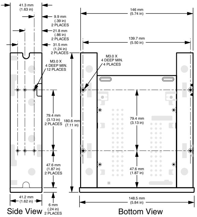
Figure 5. Mounting Holes for Internal DAT24 Drive in 5.25-inch Configuration (with mounting brackets)
Connecting Power and Interface Cables
Attach the power and SCSI interface cables to the appropriate connectors on the back of the drive. Figure 6 on page 17 shows the locations of these connections.
Connecting the SCSI Interface Cable
Turn off all power to the drive and host computer. Attach the SCSI cable, making sure to align pin 1 on the cable with pin 1 on the drive. Pin 1 on the SCSI connector is to your right as you look at the back of the drive (see Figure 6). Your SCSI cable should have pin 1 highlighted by a colored stripe.
Connecting the Power Cable
Attach a 4-pin power connector from the system power supply to the connector on the back of the drive. The recommended 4-pin power connector for the internal drive is an AMP 1-48024-0 housing with AMP 60617-1 pins or equivalent.
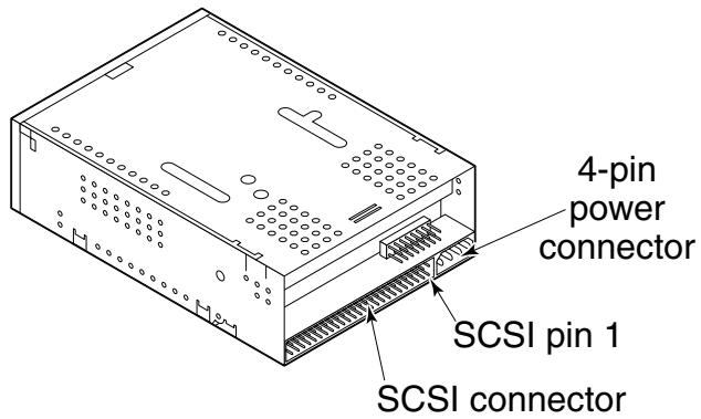
Figure 6. Locations of SCSI Interface and Power Connectors on the Internal Drive
Installing the Desktop DAT24 Drive
The desktop DAT24 tape drive is a compact external unit that connects to the host computer as a turnkey subsystem. Installing the external drive involves the following steps:
- Configure the drive. See "Configuring the Desktop DAT24 Drive" on page 18.
- Set the SCSI ID. See "Setting the SCSI ID" on page 18.
- Connect the SCSI interface cable. See "Connecting the SCSI Interface Cable" on page 19.
- Connect the power cord. See "Connecting the Power Cord" on page 19.
- Registering the tape drive. After you install the DAT24, register it. Registering it ensures that you will receive the latest information about the drive, as well as other product, service, and support information. For your convenience, you can register the DAT24 through our Web site at http://register.certance.com.
Configuring the Desktop DAT24 Drive
The following is the default configuration for desktop DAT24 tape drive:
- Drive reads and writes both MRS and non-MRS 4-mm media.
- Parity checking is disabled.
DDS-DC data compression is enabled.
POST is disabled.
Termination power is supplied to the SCSI bus.

NOTE: Some configuration settings can be changed using the SCSI Mode Select command. SCSI command information for Certance DAT drives is provided in the product description manual.
Setting the SCSI ID
Be sure the drive is turned off; then set the SCSI ID for the drive using the push-button switch on the back of the external drive. Figure 7 on page 19 shows this switch, as well as the two SCSI interface connectors, the on/off switch, and the power-cord connector.

NOTE: The drive must be restarted, or a SCSI bus reset must be issued to have the new SCSI ID take effect.
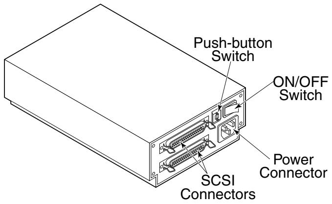
Figure 7. Rear Panel of the Desktop Drive
Connecting the SCSI Interface Cable
The desktop DAT24 tape drive has two SCSI connectors to allow daisy chaining (see Figure 7 on page 19. You can use either connector to attach the drive to the host computer or to another SCSI device.

NOTE: Turn off all power before connecting or disconnecting SCSI cables or terminating plugs.
If the desktop drive is the last device or the only device in a SCSI chain, install a terminating plug on the unused SCSI connector. Figure 8 on page 19 shows two SCSI termination examples.
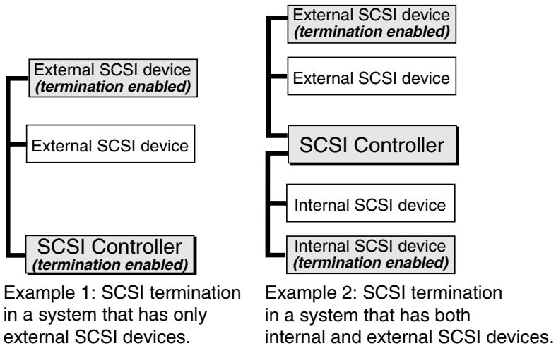
Figure 8. SCSI Termination Examples
Connecting the Power Cord
Attach the power cord securely to the power connector on the back of the drive. Figure 7 on page 19 shows the location of the power connector.
3 Operation
Introduction
This chapter describes how to use your internal or external DAT24 tape drive.
Topics covered in this chapter are:
"Loading a Cartridge" on page 20
- "Unloading a Cartridge" on page 21
- "Initializing a Blank DAT Cartridge" on page 21
"DAT Cartridge Compatibility" on page 22

Caution. To avoid data loss, clean the drive heads using a DDS head-cleaning cartridge after every 25 hours of read/write operation, or whenever the green cartridge-status LED flashes during operation. See page 23 for cleaning procedure.
Loading a Cartridge
The DAT24 tape drive has a front-loading cartridge bay for easy operation. The drive-bay door opens automatically when a cartridge is inserted. Figure 9 on page 20 shows a cartridge being inserted into a 3.5-inch internal drive. After you insert the cartridge, there will be a brief delay while the drive identifies the cartridge type and state and moves the tape to the data area.
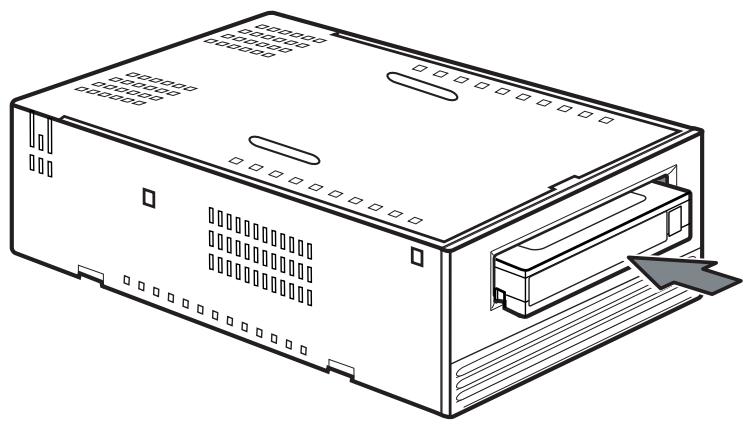
Figure 9. Loading a DAT Tape Cartridge (3.5-inch drive)
Unloading a Cartridge

Caution. Do not push the eject button while the Drive Status LED is ON. Otherwise, you may lose data.
Be sure the drive-status LED is not lit. Then unload the cartridge by pressing the eject button. For the location of the eject button, see Figure 10 on page 21. After you press the eject button, the drive automatically flushes the drive buffer to tape, updates the system log, and rewrites the cartridge before ejecting it.

NOTE: Several seconds may elapse between the time you press the eject button and the time the cartridge is ejected. Do not power down the tape drive or the host computer during this time.
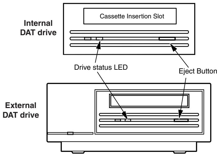
Figure 10. Location of Tape Eject Button and Drive Status LED
Initializing a Blank DAT Cartridge
When you insert a blank cartridge into the drive for the first time, the drive takes about 10 to 12 seconds to determine that the tape is blank. The drive automatically initializes the tape as soon as it receives a Write command from the host computer. Initializing a blank tape takes about 30 seconds.
While a tape is being initialized, the normal write operation continues until all internal buffers are filled. Ejecting the cartridge before the initialization is complete causes the procedure to abort. The initialization restarts from the beginning the next time a Write command is received.

NOTE: The data buffer of the drive is flushed to tape if a Rewind command is issued, if the eject button is pushed, or if a delay in SCSI activity occurs. By default, the delay before the flush occurs is set to one minute. However, this delay time can be modified by the host application using a Mode Select command.
DAT Cartridge Compatibility
The DAT24 tape drive is designed to use data-grade DDS DAT cartridges that comply with ANSI specifications listed in the "3.81 mm Helical-Scan Digital Computer Tape Cartridge for Information Interchange," ANSI X3B5/89-156 standard. To ensure optimal data integrity and reliability, we recommend using Certance-brand DDS-3 cartridges (CDM24).
The DAT24 drive also recognizes 120-meter MP+ cartridges and other MRS cartridges when MRS is enabled. MRS cartridges have a series of alternate opaque and clear stripes at the beginning of the tape. These stripes classify the media as data-grade, rather than audio-grade.

NOTE: A slowly flashing green LED in conjunction with the yellow LED indicates that a prerecorded audio tape has been inserted in the drive.
Four recognition holes allow the drive to identify the type of tape, determine its magnetic thickness, and to determine whether the tape is prerecorded or unrecorded or is a cleaning cartridge. Other cartridge features that allow the drive to optically sense cartridge in are Beginning-of-tape and End-of-tape.
Write-Protecting a DAT Cartridge
Figure 11 on page 22 shows how to write-protect or write-enable a DAT tape using the sliding write-protect tab. You can only write data to the tape when the tab is in the closed position.
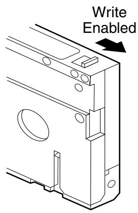
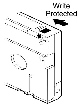
Figure 11. Write-protect Tab on a DAT Cartridge
Cleaning the Tape Heads
If excessive magnetic dust or debris collects at one or more of the tape heads, your drive may not be able to read from or write to tape. To avoid this situation, you must clean the tape heads on your DAT drive
After the first four hours of tape movement of a new cartridge.
After every 25 hours of read/write operation.
- Whenever the rectangular, green Cartridge-status LED flashes during operation.

NOTE: A slowly flashing green LED may indicate that a tape is damaged or is nearing the end of its life. If cleaning the head does not correct the flashing LED condition, replace the cartridge. The slowly flashing LED does not indicate a loss of data, nor does it indicate SCSI problems.
To clean the tape heads on your DAT drive, use only a Certance-qualified DDS DAT cleaning cartridge designed for DAT drives, such as Certance Model CDMCL.
After you insert the cleaning cartridge, the drive detects that the cartridge is a cleaning cartridge, then loads and runs the cartridge for about 30 seconds. When cleaning is complete, the drive ejects the cartridge.
Each time the cleaning cartridge is loaded, a new, unused portion of cleaning tape is advanced over the entire tape path. The drive does not rewind a cleaning cartridge. After about 30 cleaning cycles the entire tape is used up and you must purchase a new cleaning cartridge.
If you insert a cleaning tape that has been used up, the drive ejects the tape without completing a cleaning operation. This process takes just under 25 seconds.

NOTE: Do not use an audio DAT cleaning cartridge. The drive cannot recognize it.
LED Codes
As Figure 12 on page 24 shows, the front panel of the DAT24 tape drive has two rectangular LEDs. These two indicators provide information about both normal and error conditions.
The yellow rectangular LED indicates the condition of the tape drive.
The green LED indicates the condition of the tape cartridge.

NOTE: The external DAT24 drive also has a round, green power-on LED on the front panel.
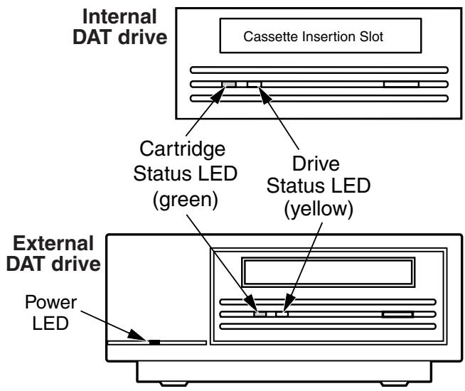
Figure 12. Status LEDs on the Front of the Drive
Table 2 on page 24 summarizes the LED flash codes for DAT24 drives.
Table 2. LED Flash Codes
| LED Color | Action | Meaning |
| Yellow | ON (lit) | The drive is reading or writing normally. |
| Yellow | Flashing Rapidly | A hardware fault occurred. |
| Green | ON (lit) | A cartridge has been inserted and is operating normally. |
| Green | Flashing Slowly | A cartridge has been inserted but is generating excessive errors beyond a predefined error threshold (warning only). Use a DDS cleaning cartridge to clean the heads. |
| Green | Flashing Rapidly | The drive could not write the tape correctly (a write error has occurred). Try using a DDS DAT cleaning cartridge to clean the heads or try a new cartridge. |
| Green and Yellow | Both flashing slowly | A prerecorded audio cartridge has been inserted and is being played automatically. |
| Green power LED (external drives) | ON (lit) | The external drive is powered on. |
Drive Status LED
The Drive Status LED is yellow and indicates the following conditions:
If the Drive Status light is ON continuously, the drive is reading or writing the tape (that is, SCSI or DAT activity is present). If you push the eject button while the Drive Status LED is ON, you may lose data.

NOTE: If a SCSI Prevent Media Removal command has been issued, the Drive Status LED remains ON until the command is canceled.
If the Drive Status LED is flashing rapidly, a hardware fault has occurred. If this occurs immediately after power-on and you have enabled the Power On Self Test (POST) through a jumper setting, the POST may have failed and the drive will not operate.
Cartridge Status LED
The green, rectangular Cartridge Status LED indicates the following conditions:
Table 3. Cartridge Status LED
| LED Status | Meaning |
| ON (lit) | A DAT cartridge has been inserted and the drive is operating normally. |
| Flashing Slowly | The tape cartridge in the drive has generated a significant number of data retries beyond a predefined DDS error threshold. This signal is a warning only and does not indicate data loss. If you see this signal, remove the tape and clean the tape heads using an approved DDS DAT cleaning cartridge. If the LED continues flashing or flashes when ejecting the cartridge, use a new cartridge for future writes. |
| Flashing Rapidly | The drive could not write the tape correctly (maximum rewrite count exceeded) and the write operation failed. Clean the drive heads using an approved DDS DAT cleaning cartridge. If the LED continues flashing, use a new cartridge for future writes |
| Cartridge Status LED and the Drive Status LED Flashing Slowly | A prerecorded audio cartridge is being played automatically. |

NOTE: As routine maintenance, you should clean the drive heads after every 25 hours of operation. See page 23.
4 UNIX Settings
Introduction
This chapter describes how to configure the DAT24 tape drive to operate on various UNIX systems. It provides drive configuration options and any changes required at the operating system level. When configured as documented in this guide, the drive performs as an integrated component of the system, giving maximum functionality.
Topics covered in this chapter are:
- "Setting DIP Switches for UNIX Support" on page 26
"Configuring Inquiry Strings" on page 27 - "Configuring for the DEC UNIX Environment" on page 28
"Configuring for the Sun Environment" on page 29 - "Configuring for the SGI Environment" on page 30
- "Configuring for the HP-UX Workstation Environment" on page 32
"Configuring for the IBM AIX Environment" on page 33
"Configuring for the SCO Environment" on page 34
Setting DIP Switches for UNIX Support
Switches 9 and 10 on the bottom of the DAT24 tape drive are used for UNIX support, as shown in Table 4 on page 26.
Table 4. Drive Configuration Settings
| System | Switch 9 Setting | Switch 10 Setting |
| Sun | OFF | ON |
| DEC | ON | OFF |
| IBM | OFF | ON |
| HP | OFF | OFF |
| SGI | OFF | OFF |
| SCO | OFF | OFF |
| Non-UNIX | OFF | OFF |
Configuring Inquiry Strings
The DAT24 tape drive returns different inquiry strings, based on the setting of Switch 7 (see Table 5 on page 27).
Table 5. Inquiry Strings
| Inquiry String Returned | Switch 7 Setting |
| ARCHIVE Python 04106-XXX | OFF |
| SEAGATE DAT 04106-XXX | ON |
Either setting for Switch 7 can be used, but the correct inquiry string must be entered in the System Configuration information. For simplicity, the ARCHIVE Python string is used in the following sections. If Switch 7 is set to ON, change the string to "SEAGATE DAT."

NOTE: There are three spaces at the end of "SEAGATE DAT" to give the same overall length as the "ARCHIVE Python" inquiry string. Be sure to insert four spaces between DAT and 04106 when the full inquiry string is required.
Table 6 on page 27 shows the PRTNO value in the inquiry string for the DAT24 tape drive. When you make the actual kernel modifications, replace PRTNO with the required number:
Table 6. DAT24 PRTNO Value
| Model Number | PRTNO Value |
| STD224000N-SB | 04106 |
Configuring for the DEC UNIX Environment
Digital UNIX Versions 4.0 and Later
With version 4.0 of their UNIX operating system, DEC introduced a new method of configuring the CAM SCSI driver. Modify the file /etc/ddr.dbase as follows:
- Locate the Database entry for the DEC TLZ07 DAT drive
- Copy this entry and paste it later in the file, taking care to maintain the file syntax.
- Modify the new entry as shown below. Modified sections are shown in bold. See "Configuring Inquiry Strings" on page 27 for information about drive inquiry strings:
SCSIDEVICE
Type = tape
Name "ARCHIVE" "Python"
PARAMETERS:
TypeSubClass = rdat
TagQueueDepth = 0 MaxTransferSize = 0x0f fffff #16MB-1)
ReadyTimeSeconds = 60 #seconds
DENSITY:
DensityNumber = 0,3,4,5,6,7 DensityCode = default
CompressionCode = 0x0 Buffered = 0x1 DENSITY:
DensityNumber = 1,2 DensityCode = default
CompressionCode = 0x1 Buffered = 0x1
- Save the file.
- Run the command ddr_config -c
ddr_config takes the default input file, ddr.dbase, and build a new device database. This is effective immediately, and there is no need to rebuild the kernel.

NOTE: ddr.dbase is a UNIX shell script and is not written in C. This means # is used to signify a comment, not / and / or //, as used in C. Make sure any comments included in this file are preceded with the # character.
Digital UNIX Versions Earlier Than 4.0
System configuration is achieved by modifying the file, cam_data.c. This is located in either /usr/ sys/data or /sys/data, depending on system configuration. Modify it as follows:
- Locate the entry for the "TLZ07 - RDAT" drive.
- Copy this entry and paste it later in the file, taking care to maintain the syntax of the C source.
- Modify the new entry as shown below. Modified sections are shown in bold. See "Configuring Inquiry Strings" on page 27 for information about drive inquiry strings:
/* Seagate DAT Drive "ARCHIVE Python" Inquiry, (Switch 7 off) */
{"ARCHIVE Python", 14, DEV_TLZ07,
(ALL_DTYPESEQUENTIAL << DTYPE_SHFT) | SZ_RDAT_CLASS,
(struct pt_info *)ccmn_null_sizes, SZ_NO_BLK, (DEC_MAX_REC - 1),
&tlz07_dens, NO_MODE_TAB, SZ_NO_FLAGS,
NO_OPT_CMDS, SZ_READY_REF, SZ_NO_QUE,
DD_REQSNS_VAL | DD_INQ_VAL, 36, 64},
- Rebuild the kernel using the doconfig script, and re-boot the system
Configuring for the Sun Environment
Sun OS 4.1.x
To configure SunOS 4.1.x explicitly to use the DAT24 tape drive, modify the stddef.h and st_conf.c files (in the directory /usr/sys/scsi/targets), then rebuild the kernel, as described below:
- Modify the stdef.h file by adding a define statement for the DAT24 tape drive similar to the one shown below:
define ST_TYPE_SEAGATE_DAT <value>
Add this line after the last ST_TYPE_ define statement in the file.
- Modify the st_conf.c file by adding the following lines at the end of the device definition list. See "Configuring Inquiry Strings" on page 27 for information about drive inquiry strings:
/*Seagate DAT support */
{ "Seagate DAT Drive",14,"ARCHIVE Python",ST_TYPE_SEAGATE_DAT,10240, (ST_variable|ST_BSF|ST_BSR|ST_long_ERASE|ST_KNOWS_EOD|ST_long_IO), 5000,5000, {0x0,0x8c,0x8c,0x8c}, {0,0,0,0} }
- Use the config command to rebuild the kernel and include the new device definition. Refer to the config man page for details
Solaris 2.x
To configure Solaris 2.x to use the DAT24 tape drive, add the following lines to the file st.conf in the directory /kernel/drv.
tape-config-list= "ARCHIVE Python PRTNO-XXX","Seagate DAT Drive","SEAGATE_DAT"; SEAGATE_DAT = 1,0x2c,0,0xd639,4,0x00,0x8C,0x8C,0x8C,3;

NOTE: The inquiry string above contains one space between Python and PRTNO. See the beginning of this chapter for information about replacing PRTNO with the number applicable to your DAT24 drive.
Once st.conf has been modified, the kernel must be reconfigured by booting the system using the boot -r command
Configuring for the SGI Environment
lrix V5.x
To configure Irix 5.x to use the DAT24 tape drive, modify the file /var/sysgen/master.d/scsi as described below:
- Add the following entry to the file /var/sysgen/master.d/scsi.
{DATTape,TPDAT,7,12,"ARCHIVE","Python PRTNO"/\*DAT\*/,0,0,{0,0,0,0}, MTCAN_BSF|MTCAN_BSR|MTCAN_APPEND|MTCAN_SETMK|MTCAN_PART|MTCAN_PREV | MTCAN_SYNC|MTCAN_SPEOD|MTCAN_CHKRDY|MTCAN_var|MTCAN_SETSZ | MTCAN_SILI|MTCAN_SEEK|MTCAN_CHTYPEANY, /\* minimum delay on i/o is 12 minutes,to allow the Drives \* full error recovery sequence to be performed. \*/ 40,12\*60,12\*60,12\*60,512,512\*512},
- Rebuild the kernel, as described below.

NOTE: The main difference between support on lrix 5.x and 6.x is the introduction of Data Compression switching via software in lrix version 6.2. When running 5.x, the drive always operates in the compression setting determined by Switch (OFF = compression enabled (default), ON = compression disabled).
See the beginning of this chapter for information on changing the inquiry string and replacing PRTNO with the number applicable to your DAT24 drive.
lrix V6.x
To configure lrix 6.x to use the DAT24 tape drive, modify the files /var/sysgen/master.d/scsi and / dev/MAKEDEV.d/TPS_base, then rebuild the kernel, as described below:
- Add the following entry to the file /var/sysgen/master.d/scsi
{ DATTAPE, TPDAT, 7, 12, "ARCHIVE", "Python PRTNO"/*DAT*, 0, 0, {0}, /* This drive uses mode select page 0xf for compression control; * most of the other drives supporting compression use page 0x10 */ MTCAN_BSF|MTCAN_BSR|MTCAN_APPEND|MTCAN_SETMK|MTCAN_PART|MTCAN_PREV|MTCAN_SYNC|MTCAN_SPEOD|MTCAN_CHKRDY|MTCAN_var|MTCAN_SETSZ|MTCAN_SILI|MTCAN_SEEK|MTCAN_CHTYPEANY|MTCAN_COMPRESS, /* minimum delay on i/o is 12 minutes, to allow the Drives * full error recovery sequence to be performed. */ 40, 12*60, 12*60, 12*60, 512, 512*512, 0, (u_char *)0 },
- For IRIX 6.x versions other than 6.4, make the following modification to the file /dev/MAKEDEV.d/TPS_base (this modification is not required on systems running IRIX 6.4).
Locate the area of code that deals with DAT drives. This starts with:*
Drive?type:\*DAT\*
Insert the following before or after the similar entries for other supported devices:
\*Device:\*Python\*PRTNO*) # DAT drive with compression
mdev=`expr $mdev + 8`;
mknod prf1c c C_TPSmdev;
;;

NOTE: TPS_base is a script, not a C source file. Using the C comment characters, / / and // causes the MAKEDEV script to fail and device drivers will not be created. Always use the shell comment character, #, in this file.
- Rebuild the kernel, as described below.
See "Configuring Inquiry Strings" on page 27 for information about changing the inquiry string and replacing PRTNO with the number applicable to your DAT24 drive.
Rebuilding the Irix Kernel
- Once the modifications are made, rebuild the kernel. This can be done using the autoconfig command (see the autoconfig man page for details). Alternatively, Irix 5.3 and later detect the changes made and automatically rebuild the kernel the next time the system boots.
- Once the new Kernel is built you will need to reboot the system again to bring the changes into effect.
Troubleshooting Installation Problems on the SGI Platform
Checking the Drives Inquiry String
You can configure the DAT24 tape drive to return different inquiry strings. Consequently, before making the changes described in this chapter, it may be useful to check the drive's inquiry string using the mt command. The following example retrieves the inquiry string and other status data from a DAT24 tape drive on SCSI bus 1, ID 4.
mt -f /dev/rmttps1d4 status
System Interchange Problems
If the following error appears when trying to restore a cpio archive from another system, a mistake has been made in the installation sequence above:
Byte swapped Data - re-try with correct device
If this error is encountered, it is probably caused by incorrect setup, as described above, Check and verify the correct modifications were made to /var/sysgen/master.d/scsi.
Switching Hardware Compression
Support for switching Hardware Compression is supported in Irix 6.x by using different device drivers. Drivers including a c in the device name should enable compression. Problems seen with compressed operation can be resolved by installing the latest Irix 6.x patch set.
Configuring for the HP-UX Workstation Environment
HP-UX Versions 10.2 and Later
- Log in as root.
- Run the SAM utility.
- Choose the Peripheral Devices option.
- Choose Tape Drives.
- From the Actions menu in the Tape Device Manager window, choose Add.
- Within the Add a Tape Drive window, read the instructions, then click on OK.
- SAM may detect that your HP-UX kernel lacks the drivers necessary to make use of the Tape Drive. If so, read the message in the Device Driver Check window and choose the appropriate action. If you choose Build a new kernel and shut down the system immediately, SAM creates a new kernel and automatically reboots the system. After the system comes back up, the necessary drivers are loaded and the system can use the tape drive.
If you had to shut down the system to physically connect the tape drive, re-enter SAM and repeat steps 3 to 6.
- Choose the new tape drive.
- From the Actions menu, choose Create Device Files.
- Press OK and exit SAM.
Configuring for the IBM AIX Environment
AIX Versions 3.2 and Later
The DAT24 tape drive can be configured to work with AIX versions 3.2 and later by using the SMIT Other SCSI Tape Drive option. Record the SCSI ID of the tape drive before installing it.
To configure AIX using the SMIT utility, use the following procedure:
- To enter SMIT at the Tape Drive menu, type smit tape.
- Select Add a tape Drive.
- Using the Other SCSI Tape Drive option, select the type of tape drive you will be adding.
- Select the Parent SCSI Adapter from the available list
-
When the Add a Tape Drive Entry Fields appear, change some of the standard options to maximize drive performance and functionality:
-
Set the Connection Address with the Drives Target and Lun (always use Lun 0). In the list, the Target is the first number and the Lun is the second. For example, if the drive is ID 5, choose 5,0.
- Set the Fixed Blocksize to 1024.
- Set Density 1 to 140.
-
Set the Maximum delay for the Read/Write command to 900.
-
Press the Return key to install the drive in the system database and create the devices.
-
Exit SMIT
AIX Device Drivers and Switching Data Compression
After you use SMIT to install the tape drive, device files are created for accessing the tape drive. Typical examples are:
/dev/rmt0 /dev/rmt0.1 /dev/rmt0. dev/rmt0.3
/dev/rmt0.4 /dev/rmt0.5 /dev/rmt/0.6 /dev/rmt/0.7
With the configuration information provided here, devices rmt0, rmt0.1, rmt0.2, and rmt0.3 cause the drive to write in compressed mode. Using devices rmt0.4, rmt0.5, rmt0.6, and rmt0.7 causes the drive to write with compression disabled.
Configuring for the SCO Environment
The following versions of SCO UNIX that run on the PC platforms support the DAT24 drive using the standard switch settings (Switches 9 and 10 OFF).
SCO UNIX (including ODT and Open Server)
SCO UnixWare
Xenix
Once connected to the system, use the command mkdev tape install the drive. See the online manual pages for the mkdev command for specific installation details about each SCO variant.
Index
C
Cartridge
compatibility 22
initializing 21
loading 20
unloading 21
write-protecting 22
Cartridge Status LED 25
Cleaning tape heads 23
Compatibility of DAT cartridges 22
Configuration
desktop drive 18
internal drive 11
Connecting power cable
desktop drive 19
internal drive 17
Connecting SCSI interface cable
desktop drive 19
internal drive 17
D
DAT cartridge compatibility 22
DAT24
models 9
overview 9
unpacking 10
DAT24 desktop drive
configuration 18
connecting power cable 19
connecting SCSI interface cable 19
installation 18
SCSI ID 18
DAT24 internal drive
changing DIP switch settings 12
configuration 11
connecting power cable 17
connecting SCSI interface cable 17
DDS pass-through 13
guidelines and cautions 11
inquiry string 13,27
installation 10
jumper settings 14
Media Recognition System 13
mounting 15
parity check 13
Power On Self Test 14
remote SCSI address selection 15
SCSI ID 12
SCSI termination 15
terminator power 15
UNIX operating systems 14, 26
DDS pass-through 13
DEC UNIX
Digital UNIX earlier than v4.0 29
Digital UNIX v4.0 and later 28
DEC UNIX environment 28
DIP switch settings, internal drive 12
Drive Status LED 25
F
Flash codes 23
G
Guidelines and cautions, internal drive 11
H
HP-UX environment 32
v10.2 and later 32
1
IBM AIX environment 33
v3.2 and later 33
Initializing a blank cartridge 21
Inquiry string 13, 27
Inspection 10
Installation
desktop DAT24 18
internal DAT24 10
Irix v5.x 30
lrix v6.x 31
J
Jumper settings 14
L
LED flash codes 23
LEDs
Cartridge Status 25
Drive Status 25
Loading a cartridge 20
M
Media Recognition System 13
Models 9
Mounting internal drive 15
in a 3.5-inch drive bay 15
in a 5.25-inch drive bay 16
P
Parity check 13
Power On Self Test 14
R
Remote SCSI address selection 15
s
SCO environment 34
SCSI ID
desktop drive 18
internal drive 12
SCSI termination
internal drive 15
Setting SCSI ID
desktop drive 18
internal drive 12
SGI environment 30
Irix v5.x 30
lrix v6.x 31
Solaris OS 2.x 30
Sun OS 4.1.x 29
Switches, internal drive 12
T
Tape heads, cleaning 23
Terminator power, internal drive 15
U
UNIX operating systems
DEC UNIX environment 28
Digital UNIX
earlier than v4.0 29
v4.0 and later 28
HP-UX environment 32
v10.2 and later 32
IBM AIX environment 33
IBM AIX v3.2 and later 33
SCO environment 34
SGI 30
IRIX v5.x 30
IRIX v6.x 31
Solaris 2 × 30
Sun OS 4.1.x 29
switch settings 14, 26
Unloading a cartridge 21
Unpacking 10
W
Write-protecting a cartridge 22