700T - Laptop MAXDATA - Free user manual and instructions
Find the device manual for free 700T MAXDATA in PDF.



| Product type | Laptop |
| Brand | MAXDATA |
| Model | 700T |
| Processor | Intel Pentium III SpeedStep, 400 MHz to 700 MHz |
| RAM | 32 MB to 256 MB, SDRAM SO-DIMM, 2 slots |
| Hard drive | Removable, IDE interface, standard 9.5 mm or 12.7 mm |
| Screen | TFT 13.3" SVGA or 14.1" XGA (800x600 or 1024x768) |
| Floppy disk drive | 3.5", 1.44 MB |
| Optical drive | CD-ROM 32x or DVD-ROM 8x |
| Connectivity | 2x USB, 2x PCMCIA Type II, VGA, S-Video, RJ11 (modem), RJ45 (LAN), IEEE 1394, IrDA, PS/2, serial, parallel |
| Audio | Stereo speakers, built-in microphone, headphone jack, microphone input |
| Touchpad | Built-in TouchPad, PS/2 compatible |
| Keyboard | 87 keys with integrated numeric keypad, Windows keys |
| Battery | Rechargeable Li-Ion or NiMH, battery life approx. 2 to 3 hours |
| Power supply | AC adapter 100-240 V, auto-switching |
| Dimensions (W x D x H) | 305.0 mm x 250.0 mm x 39.5 mm |
| Weight | 3.2 kg (with 14.1" TFT screen) |
| Power management | APM and ACPI, Suspend-To-RAM and Suspend-To-File modes |
| Security | Supervisor and user password, keyboard lock |
| Supported operating systems | Windows 98, Windows NT 4.0, Windows 2000, DOS |
| Operating conditions | Temperature: 10°C to 35°C; Humidity: 20 to 80% non-condensing |
Frequently Asked Questions - 700T MAXDATA
User questions about 700T MAXDATA
0 question about this device. Answer the ones you know or ask your own.
Ask a new question about this device
Download the instructions for your Laptop in PDF format for free! Find your manual 700T - MAXDATA and take your electronic device back in hand. On this page are published all the documents necessary for the use of your device. 700T by MAXDATA.
USER MANUAL 700T MAXDATA
| AMIBIOS HIFLEX ENGLISH SETUP - VERSION 1.19 (C)2000 American Megatrends, Inc. All Rights Reserved |
| BIOS Revision 700A_A0x |
| Standard CMOS Setup |
| Advanced CMOS Setup |
| System Security Setup |
| Power Management Setup |
| Boot Device Setup |
| Peripheral Setup |
| Auto Configuration with Defaults |
| Save Settings and Exit |
| Exit Without Saving |
| Standard CMOS setup for changing time, date, hard disk type, etc. ESC: Exit ↑↓: Sel F3/F4:Color F10:Save & Exit |
| AMIBIOS SETUP - ADVANCED CMOS SETUP (C)2000 American Megatrends, Inc. All Rights Reserved | |
| Video out Type NTSC LCD Panel View Expansion On Internal Mouse Enabled Suspend Warning Tone Enabled Intel(R)SpeedStep(TM)Technology Automatic | Select the appropriate Video Standard for your country. 'NTSC' is for USA/Japan, and 'PAL" is for Europe. ESC: Exit ↑↓: Sel PgUp/PgDn: Modify F3/F4: Color |
LCD Panel View Expansion:
Suspend Warning Tone:
| AMIBIOS SETUP - SYSTEM SECURITY SETUP (C)2000 American Megatrends, Inc. All Rights Reserved | ||
| Change Supervisor Password | Press Enter | If supervisor password is entered, the system requires the supervisor password to enter this Setup utility. Pressing Ctrl-Alt-Backspace locks up the keyboard until the password is entered. The Cap Lock and Scroll Lock LEDs will flash in sequence while waiting for the user to enter a password. |
| Change User Password | Press Enter | |
| Boot Password Required | No | |
| Resume Password Required | No | |
| ESC: Exit ↑↓: Sel PgUp/PgDn: Modify F3/F4: Color | ||
Change Supervisor Password (Hauptpassword):
Boot Password Required:
Resume Password Required:
| AMIBIOS SETUP - POWER MANAGEMENT SETUP (C)2000 American Megatrends, Inc. All Rights Reserved | ||
| Power Switch | Power Button | Use 'Power Button' to power the system On or Off. Use 'Sleep Button' to enter or resume from suspend mode. |
| Power Management Under AC Power Off | ||
| Power Saving Level | Off | |
| Hard Disk Time-out | Off | |
| Video Time-out | Off | |
| Standby Time-out | Off | |
| Auto Suspend Time-out | Off | |
| LCD Suspend | Disabled | |
| Suspend Option | Suspend | |
| Auto Save To File | Disabled | |
| Wake Up Alarm | Disabled | |
| Resume Alarm Time | Off | |
| ESC: Exit ↑↓: Sel PgUp/PgDn: Modify F3/F4: Color | ||
Power Switch:
Power Management Under AC Power:
Auto Suspend Time-out:
| AMIBIOS SETUP - BOOT DEVICE SETUP (C)2000 American Megatrends, Inc. All Rights Reserved | ||
| Quick Boot | Enabled | „Enabled“ allows the system to skip part of test during system is booting. |
| Silent Boot | Enabled | |
| Boot Display Device | Simul. Mode | |
| BootUp Num-Lock | Off | |
| 1stBoot Device | CD/DVD | |
| 2ndBoot Device | Floppy | |
| 3rdBoot Device | 1stIDE-HDD | |
| Try Other Boot Devices | Yes | |
| ESC: Exit ↑↓: Sel PgUp/PgDn: Modify F3/F4: Color | ||
Quick Boot:
Try Other Boot Devices:
11.8 Peripheral Setup (Peripherie-Setup)
| AMIBIOS SETUP - PERIPHERAL SETUP (C) 1998 American Megatrends, Inc. All Rights Reserved | ||
| Internal Hard Drive | Enabled | Available Options: Enable Disabled |
| OnBoard Serial Port1 | Auto | |
| OnBoard Parallel Port1 | ECP | |
| ESC: Exit ↑↓: Sel PgUp/PgDn: Modify F3/F4: Color | ||
Internal Hard Drive:
CLASS 1 LASER PRODUCT KLASSE 1 LASER PRODUKT

Specifications and information found in this manual are subject to change without notice. Any changes therefore will be incorporated in future editions. The manufacturer assumes no responsibility for errors or omissions in this document.
TRADEMARKS
MS-DOS, Windows 98, Windows 2000, and Windows Millennium are trademarks of Microsoft Corporation.
Pentium III (, PIII), and SpeedStep are trademarks of Intel Corporation.
Other trademarks are properties of their respective owners.
Standards
The following standards are adopted throughout this manual:
Notebook in boldface (with or without capitalization) refers to the notebook computer which you have purchased.
Boldface type is also used to highlight important information in this document.
The messages which appear on the Notebook screen will be boxed when they are referenced.
Whenever extra caution is called for, the information will be boxed in a dark frame preceded by "Note:" or "Warning:"
Usually after performing a step-by-step instruction, you will be asked to: Press the Esc key Which means you should press the Esc key located at the upper left-hand corner of the keyboard.
CONTENTS
CHAPTER 1 INTRODUCTION. 1-1
1.1 STANDARD FEATURES 1-3
1.2 SPECIAL FEATURES 1-7
CHAPTER 2 BEFORE YOU BEGIN. 2-1
2.1 CHECKING WHAT YOU RECEIVED 2-1
2.2 EXAMINING YOUR COMPUTER 2-2
2.3 THE TWO POWER LEDs 2-6
2.4 THE SEVEN SYSTEM LEDs 2-7
CHAPTER 3 KEYBOARD 3-1
3.1 GENERAL VIEW 3-2
3.2 THE EMBEDDED NUMERIC KEYPAD 3-3
3.3 OTHER KEYS 3-3
CHAPTER 4 FDD/HDD DRIVES. 4-1
4.1 THE FLOPPY DISKETTE DRIVE (FDD) 4-1
4.2 REMOVAL HARD DISK DRIVE (HDD) 4-2
4.3 REMOVING THE HARD DISK DRIVE 4-3
CHAPTER 5 THE LCD SCREEN. 5-1
5.1 ADJUSTING CONTRAST-BRIGHTNESS 5-1
5.2 LCD/CRT/TV DISPLAY 5-2
5.3 RESOLUTIONS AND COLORS 5-2
CHAPTER 6 BATTERY 6-1
6.1 BATTERY PACK. 6-1
6.2 RECHARGING THE BATTERY PACK 6-1
6.3 QUESTIONS AND ANSWERS: 6-1
6.4 BATTERY BUTTON, LEDs AND ALARM.. 6-3
6.5 BATTERY MAINTENANCE 6-4
6.6 POWER CONSUMPTION 6-4
6.7 REDUCING POWER CONSUMPTION 6-6
6.8 REMOVING/INSERTING THE BATTERY PACK 6-6
CHAPTER 7 MEMORY 7-1
7.1 INSERTING/REMOVING MEMORY MODULE 7-2
CHAPTER 8 THE CD/DVD-ROM DRIVE. 8-1
8.1 THE CD/DVD-ROM DRIVE PANEL 8-1
8.2 DISC LOADING/EJECTION 8-2
8.3 ROM DISC MAINTENANCE 8-2
CHAPTER 9 PERIPHERALS 9-1
9.1 PS/2 KEYBOARD CONNECTOR 9-1
9.2 PARALLEL PORT 9-1
9.3 COM PORT 9-1
9.4 USB CONNECTOR 9-2
9.5 VGA CONNECTOR 9-2
9.6 S-VIDEO CONNECTOR 9-2
9.7 AUDIO JACKS 9-2
9.8 PCMCIA PORT 9-3
9.9 IRDA PORT 9-3
9.10 FAX PORT 9-3
9.11 ETHERNET LAN PORT 9-3
9.12 IEEE 1394 PORT 9-4
CHAPTER 10 THE CD-ROM DISC 10-1
10.1 DOS UTILITIES AND DRIVERS 10-1
10.2 WINDOWS 98 DRIVERS AND APPLICATIONS 10-2
10.3 WINDOWS NT 4.0 DRIVERS AND APPLICATIONS 10-2
CHAPTER 11 CONFIGURING YOUR SYSTEM. 11-1
11.1 CONFIGURATION SOFTWARE 11-1
11.2 RUNNING THE SETUP UTILITY 11-2
11.3 STANDARD CMOS SETUP 11-3
11.4 ADVANCED CMOS SETUP 11-5
11.5 SYSTEM SECURITY SETUP 11-7
11.6 POWER MANAGEMENT SETUP 11-9
11.7 BOOT DEVICE SETUP 11-13
11.8 PERIPHERAL SETUP 11-15
11.9 AUTO CONFIGURATION WITH DEFAULTS 11-16
11.10 SAVE SETTINGS AND EXIT 11-16
11.11 EXIT WITHOUT SAVING 11-16
APPENDIX A - CONNECTORS AND PIN ASSIGNMENTS. A-1
APPENDIX B - HOT-KEYS. B-1
APPENDIX C - GLOSSARY. C-1
APPENDIX D - PORT REPLICATOR. D-1
APPENDIX E - OTHER KEYBOARDS. .E-1
APPENDIX F - ERROR LOG. .F-1
APPENDIX G - AGENCY REGULATORY NOTICES............G-1
Chapter 1 Introduction
Thank-you for purchasing our latest state-of-the-art Multimedia notebook computer! Whether you are a no-nonsense traveling business executive, who are occasionally tied down by your company's local area network, or a die-hard multimedia fan who spends elaborated hours on the internet; you will find your investment on this notebook worth the money you have paid for a long time to come.
You are holding one of the most powerful, feature-rich and expandable notebook ever made. We encourage you to read over this manual to familiarize yourself with all the capabilities that your machine has to offer. For those of you who just cannot wait to get start, please take time to read the Safety Instructions at the very beginning of this manual, the Overview in this chapter, the basic operations in Chapter 2, and Configuring Your System as explained in Chapter 11. Then you can go ahead and get start with your new notebook!
Overview
Internally, the notebook uses the Intel's latest generation of Pentium III SpeedStep processor, and Intel's premium North-Bridge/South-Bridge PCI bus architecture. The ATI's latest VGA chip-set together ESS's audio chip-set has made this notebook an ideal choice for sober MultiMedia lovers. Externally, the notebook provides a wide choice of ports and connectivity; such as PCMCIA socket, USB ports, infrared port, internal fax/modem port (optional), LAN connection port (optional), external CRT, Television (NTSC/PAL), and many others. This would definitely make the life of a travel executive a lot easier, off-site, at home, and in the office.
With this notebook, upgrades have never been easier. You can switch CPU processor among the Intel's Pentium III 400MHz to 700MHz. Your system memory is easily upgradeable from 64MB up to 512MB. The hard disk system can handle most of the 9.5mm or 12.7mm IDE industry standard drives, giving you virtually unlimited storage capability.
Battery life (or more appropriately the duration of which a notebook unit be able to operate without an AC outlet) is an important issue. Knowing this, we have incorporated the latest Advanced Power Management (APM) and/or Advanced Configuration Power Interface (ACPI) for energy saving.
While we hope that this overview has made you aware of some the most exciting features of your new computer, there is still much more to the notebook. The remainder of this manual is dedicated to helping you get the most out of your new notebook. Please read each chapter carefully and we recommend you to explore each of the explained functions.
Now, read on to find out more about what the amazing notebook can do for you!
1.1 Standard Features
SYSTEM
Intel µ PGA-II Pentium III 400MHz to 700MHz with 64KB L1 cache and 128KB/256KB L2 cache.
Core Logic: North Bridge, Intel AGPset FW82443ZXM-100. South Bridge, Intel PCIset PIIX4 FW82371.
- Two S.O. DIMM memory sockets upgradeable from the basic 32MB to 256MB memory.
256Kb Flash ROM contains BIOS and is easily user upgradeable.
- Hard Disk Drive (HDD) is conveniently user changeable.
DISPLAY
ATI RAGE Mobility-M1 PCI/AGP 1x/2x with MCM memory 8MB.
- LCD only, CRT only, TV only, and LCD/CRT simultaneous.
Display Panel: TFT 13.3" XGA, 1024768 TFT 14.1" XGA, 1024768
STORAGE DEVICE
- User changeable industry standard 9.5mm hard disk drive, or latest Ultra DMA 33 hard disk drive.
- Industry standard 3.5inch 1.44MB floppy disk drive.
32x CD-ROM, or 8x DVD-ROM drive.
KEYBOARD
87 full keys, including 2 Windows keys, and embedded numerical keypad.
- External PS/2 keyboard connector located on the back of notebook.
CONNECTIVITY and EXPANSION
Built-in TouchPad, IBM PS/2 mouse compatible.
One Serial D-type 9-pin COM1 connector.
One 6-pin mini DIN external keyboard, or PS/2 mouse connector.
One 15-pin D-type connector for external VGA monitor.
- One parallel port 25-pin D-type for printer, or pocket LAN. High-speed bidirectional port under either hardware or software control (EPP/ECP compliance).
Two type 2 PCMCIA slots.
- Two USB connectors.
Oneearphone connector.
One external microphone-in connector (mono).
One S-Video jack for television connection.
One RJ11 Fax/Modem connector.
- One RJ45 LAN connector.
One IEEE 1394 connector.
One IrDA port.
POWER
- One battery slot to support 3000mAh Lithium Ion (Li-Ion), or 4500mAh Nickel Metal Hydride (NiMH) battery pack.
- Offline battery charging time is around two-and-a-half hours.
Full range 100 to 240V auto-switch AC adapter.
PHYSICAL
Weight (TFT color, 14.1") : 3.2kg
Length/Width/Height : 305.0mm/250.0mm/39.5mm
Note: Weight and height might change due to different configurations and models.
ENVIRONMENT
Operating Temperature : 10°C to 35°C
Non-Operating Temperature : -20°C to 60°C
Humidity : 20% to 80% non-condensing
Shock : 5G operating, 60G non-operating
Vibration : 3-200Hz @ 1.0G operating
: 3-200Hz @ 1.5G non-operating
Warning:
Don't expose your notebook to excessive heat or coldness (frost). Don't drop, spill fluids or open the exterior of the case. This can damage the notebook and void the warranty.
POWER MANAGEMENT
Industry standard Advanced Power Management (APM) 1.2, and Advanced Configuration Power Interface (ACPI) 1.0.
OPERATING SYSTEM
Windows 98 SE (ACPI or APM), Windows NT, Windows 2000, and Windows Millennium.
OPTIONS
- Standard SDRAM S.O. DIMM self-fresh 32MB, 64MB, and 128MB memory module for expansion from 32MB to 256MB.
Additional Lithium Ion (Li-Ion), or Nickel Metal Hydride (NiMH) battery pack. - LAN/Modem Combo Card for Ethernet LAN connection and Fax/Modem connection.
1.2 Special Features
Power Management
Power Saving can be switched to Customized or Disabled in the BIOS Setup.
System will enter Suspend-To-RAM mode (with the LCD panel automatically turned off), when the cover is closed.
Advanced Power Management (APM), and ACPI supports.
Depending on user's setup, system enters Suspend Mode (Suspend-To-RAM or Save-To-File) when no device activity occurs after an user selected time duration.
In Suspend-To-RAM mode, all major devices and components (including VGA chip and LCD panel) are shutdown to save energy.
In Save-To-File mode, system is completely shutdown for energy saving. Low Battery Activity allow system to save memory contents and system activities into a disk file called Save-To-File (refer to Chapter 10). When you power on the system again, the system will return to exactly where you left off.
The Hard Disk Drive, HDD, would spin down for power saving if there is no HDD access for an extended period of time.
Memory Expansion
System Memory, upgradeable from 32MB to 256MB. For more information, refer to Chapter 7.
Hot Keys
Please see Appendix B for all available Hot Key functions; such as Contrast and Brightness adjustment, and Suspend-To-RAM and Save-To-File etc.
TouchPad
The TouchPad is conveniently located, making it easily accessible to both left and right handed people. There are two buttons at the bottom of the TouchPad, emulating the right and left mouse buttons. Use your finger as a mouse pointer to draw lines or point to an item as needed. Double click (tap) on the TouchPad to simulate mouse button clicking.
Note: You are advised to clean your TouchPad with a dry cloth in a regular basis. Grease, dirt, and moisture on the TouchPad can lead to abnormal mouse operations.
PCMCIA
PCMCIA card provides many powerful features for your notebook. Many cards are available today such as: Fax/Modems, Network Adapter, and SCSI Adapters. The PCMCIA unit in your notebook provides connections to one type 2 (5mm height).
SOUND SYSTEM
This internal sound card provides you 16-bit CD-quality stereo sound, and it is Sound Blaster Pro compatible. The notebook includes built-in stereo speakers, microphone, and connectors for line-in, line-out, microphone-in, and earphone.
Chapter 2 Before You Begin
Please read this section before you start using your computer.
2.1 Checking What You Received
Your notebook package should contain the following items:

b)
c)

e)

f)
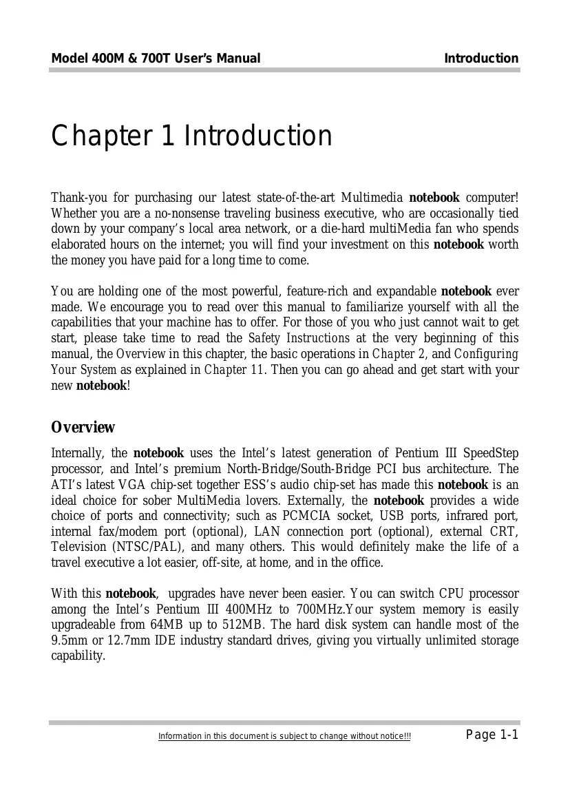
a) The notebook (without Battery Pack).
b) Battery Pack
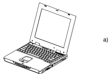
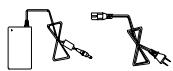
c) AC Adapter
d) AC Power Cable
e) CD-ROM Disc (for Drivers/ Utilities)
f) User's Manual
Note: You should keep the original factory carton and packing materials in case you need to ship the unit back for servicing.
2.2 Examining Your Computer
Before you start using your computer, you need to get acquainted with your notebook's main features and interfaces:
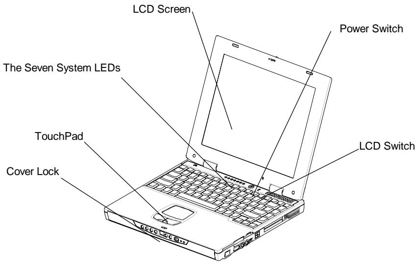
A Panoramic View of the notebook
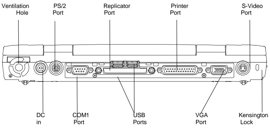
Rear View
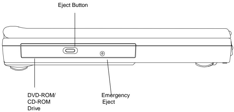
View of the Left Panel
View of the Right Panel
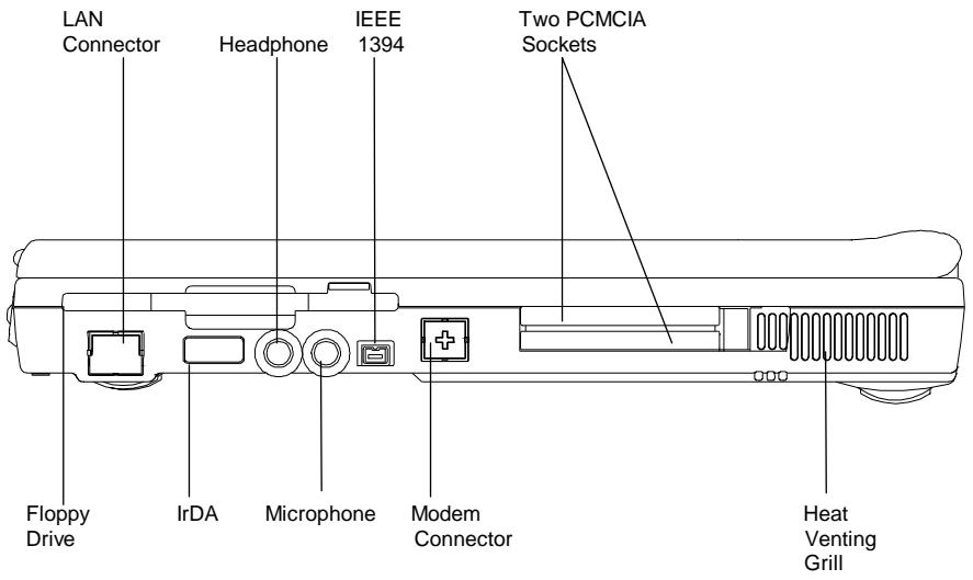
Stereo Connector: Your Earphone, Line-In, and Line-out jets should have this type of connector as shown here.

Mono Connector: Your Microphone jet should have a connector as shown here
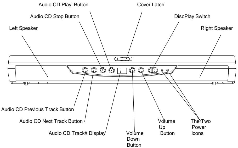
View of the Front Panel
The DiscPlay Function
Your notebook supports a state-of-the-art DiscPlay Function, whereby you can playback audio CD without booting up the system. With a fully charged battery, the system can continuous play audio CD for several hours. The buttons listed below work only when the system is in DiscPlay mode:
Audio CD Play Button
Audio CD Stop Button
Audio CD Previous Track Button
Audio CD Next Track Button
Volume Up Button
Volume Down Button
You can switch the DiscPlay Function on/off by pressing the Discplay Switch to the right. The DiscPlay can be switched ON only when the system is not booted up, or when the system is in Suspend-To-File (STF) mode.
2.3 The Two Power LEDs

The Battery Pack LED
LED on- The battery pack is being recharged
LED off- The battery pack is fully recharged
- LED flashes (1/2 second on; 1/2 second off)- The battery pack is either in Battery LOW-2 stage, or the battery pack is in pre-charge.
LED flashes (1 second on; 2 second off)- The battery pack is bad

The Power On LED
LED on- The system is powered on
LED off- The system is powered off
LED flashes- The system is in Suspend-To-RAM (S2R)
Note:
For exact location of the Two Power LEDs, please refer to the View of the Front Panel diagram in Chapter 2.2.
For more information on Battery Low-2 and pre-charge, please refer to Chapter 6.
2.4 The Seven System LEDs

The AC Adapter LED
This LED would be lit when the notebook is power by the AC power source.

The CD-ROM/DVD-ROM LED
This LED would be lit when the notebook is accessing the CD-ROM, or the DVD-ROM drive.

The HDD LED
This LED would be lit when the notebook is accessing the HDD drive.

The FDD LED
This LED would be lit when the notebook is accessing the FDD drive.

The NUM Lock LED
This LED would be lit when the keyboard is in Num Lock mode. In this mode, all the embedded numeric keystads can be used.

The CAPS Lock LED
This LED would be lit when the keyboard is in Caps Lock mode. In this mode, all alphabet characters you type are in upper case.

The Scroll Lock LED
This LED would be lit when the keyboard is in Scroll Lock mode. In this mode, you can lock cursor position while scrolling a document with the arrowScroll keys.
Note:
The Seven System LEDs are located somewhere between the LCD panel and the keyboard. For exact location, please refer to the Panoramic View diagram in Chapter 2.2.
This page is left blank intentionally.
Chapter 3 Keyboard
The notebook features an enhanced keyboard that incorporates the functions of a full-featured desktop keyboard. An embedded numeric keypad, accessed via the NumLock key is included. The screen control keys are conveniently located near the right side and lower right corner of the keyboard.
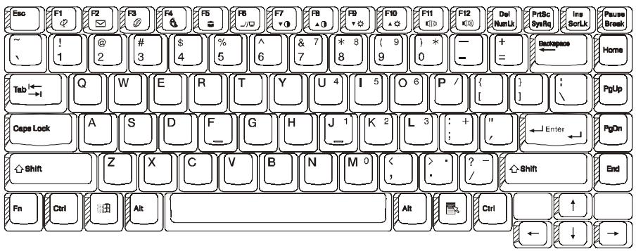
US Keyboard Layout
3.1 General View
The keyboard has a total of 87 keycaps, including 2 Windows keys. Some keycaps have multiple symbols on them. Their functions can be accessed via different key combinations:
EXAMPLE:
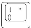
To access the "0", press the key only.
To access the ")", press the shift and the key.
To access the **, press the NumLock first, then press the key.
F1 to F12 keys are Function Keys
CapsLock Key:
When the CapsLock indicator light is on, the letters are typed in upper-case. When the CapsLock indicator light is off, all letters are typed in lower-case.
Print Screen Key:
By pressing the PrintScreen key, the characters or text shown on the screen will be printed on your printer.
Warning:
Don't press the PrintScreen key unless a printer is connected to the notebook. Otherwise the system may hang.
3.2 The Embedded Numeric Keypad
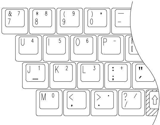
The figure below shows the embedded numeric keypads which can be activated via the NumLock key.
The NumLock key which is located near the upper right corner of the keyboard is printed in blue color, and the keys on the embedded numeric keypad are also in blue color.
3.3 Other Keys
The Fn Key:
The (Function) Fn key is located at the bottom-left corner of the keyboard. This key is used to access the notebook's system "Hot Keys" or "function keys". For example, to change the notebook into a simultaneous video mode, you hold down the Fn key while pressing the F6 key.
For more information on the Fn or Hot Keys, see Appendix B.
The Ctrl (Control) Key:
Both Ctrl keys have the same function. Holding down the Ctrl key together with another key can activate certain functions of an application program; such as Excel or Word.
The Alt (Alternate) Key:
Both Alt keys have the same function. Holding down the Alt key together with another key can activate certain functions of an application program; such as Excel or Word.
The Windows (Key:
This Windows key has the same function as selecting the START icon in Windows OS.
The Windows ( ) Key:
This Windows key has the same function as clicking the right mouse button, when in Windows OS. This key can activate certain functions of an application program; such as Excel or Word.
Chapter 4 FDD/HDD Drives
Your notebook comes with a factory-assembled Floppy Disk Drive (FDD), and removable Hard Disk Drive (HDD). For their exactly external feature and position, please refer to Chapter 4.1 and Chapter 4.2. Chapter 4.3 describes how the removable HDD can be taken out.
4.1 The Floppy Diskette Drive (FDD)
The FDD is used to transfer data to and from your hard disk via 3.5 inch diskettes. It can read and write files from both 720KB and 1.44MB (2HD) floppies formatted for IBM compatible computers. In order to use a diskette for the first time, it needs to be formatted; otherwise the computer cannot read or write to it.
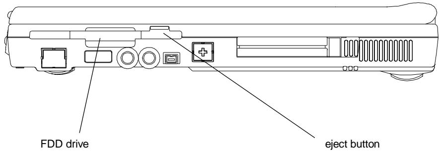
The Left View of notebook
Note: By formatting a diskette, all information in the diskette will be lost!
4.2 Removal Hard Disk Drive (HDD)
Your notebook is equipped with a replaceable HDD. The HDD can easily be upgraded to higher capacities. Your notebook is compatible with most industry standard 9.5mm IDE interface hard disk drives. Consult your dealer for more information.
When the notebook is accessing the HDD, the HDD LED (Chapter 2.4) would be lit. The hard disk would spin-down if there is no disk access for an extended period of time. Disk accessing will wake the drive up, but reading or writing is enabled after the motor spins back to normal speed. "Spin up" needs about 4~5 seconds to reach normal speed.
Note: CAUTION! Always keep a backup of your files on HDD to prevent data loss.
4.3 Removing the Hard Disk Drive
Your Hard disk drive is easily removable and can be replaced or upgraded. There are many advantages to having more than one hard disk. For example, separate hard disk for each person that uses the computer, or separate hard disks for different purposes.
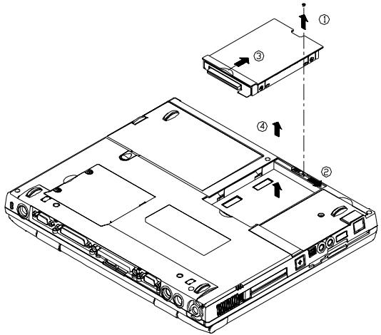
Follow these steps to remove the hard disk drive.
Make sure the system is powered off.
- Remove the screw as shown by arrow 1.
- Press the handle to the right as shown by arrow 2.
- Press the handle up as shown by arrow 3.
- Lift the HDD drive up as shown by arrow 4.
Note:
Reverse the above steps to install a hard disk drive. If you have just changed a HDD, don't forget to change the settings in Pri Master of the Main Setup, unless you have Pri Master set to Auto. For detail, see Chapter 11.3.
This page is left blank intentionally.
Chapter 5 The LCD Screen
The notebook has several screen options: DSTN (Dual Scan)/TFT (Active Matrix) with resolution/color in 800 × 600 × 64 K (SVGA) and 1024 × 768 × 64 K (XGA).
5.1 Adjusting Contrast-Brightness
The notebook uses "Hot Keys" to adjust contrast and brightness.
Contrast Control:
Press and hold down the Function key couple Fn together or Fn together to adjust the Contrast.
Note: Contrast cannot be changed on the TFT models!
Brightness Control:
Press and hold down the Function key couple Fn together or Fn together to adjust the Brightness.
5.2 LCD/CRT/TV Display
By pressing and holding down the Function key couple Fn F2 together, you can switch your display between: LCD only, CRT only, and LCD/CRT simultaneous. By pressing and holding down the Function key couple Fn F6 together, you can switch your display between LCD and TV.
Note: When you switch your display from CRT Only to LCD/CRT (simul), the following symptoms may occur:
- Depends on your CRT, the size of the screen may be different from (smaller/larger than) the size CRT displayable area.
- The displayed screen is off-centered.
- The screen flickers.
The symptoms are caused by the lower CRT refresh rate when simul display is selected. This problem is usually more severe in DSTN than in TFT. If you want a better display, you should select CRT Only.
5.3 Resolutions and Colors
TFT:
Depending on the different drivers under Windows, DOS or other operating systems; you can have different resolutions with different fonts and colors. For more information on Display Modes, run the utility software supplied with your notebook. See Chapter 10, for installation procedure.
CRT:
The resolutions on the CRT depends on both the CRT and its driver program. The VGA driver supplied can display up to 1024x768 (non-interlaced) under the Windows environment.
Note: To get the fastest speed and most colors under Windows, you need to install the VGA drivers that comes along with your notebook. For more information on how to install the drivers, see Chapter 10.
Chapter 6 Battery
6.1 Battery Pack
Depending on model, included with the notebook is one high energy rechargeable Lithium Ion (Li-Ion), or Nickel Metal Hydride (NiMH) battery pack. In general, a fully charged battery pack can support around 2-3 hours of operation, with Power Management option enabled. However, difference in configuration (CPU, HDD, Memory etc.) and system utilization (especially I/O activities) can affect the operation time greatly.
6.2 Recharging the Battery Pack
Your notebook supports both on-line and off-line recharge. Follow the procedure below to recharge battery:
- Make sure the battery pack is installed in the notebook.
- Connect the AC Adapter to the notebook and to an electrical outlet.
When a battery pack is being recharged, its Battery Pack LED would be "ON". For detail on the LEDs, please refer to Chapter 2.3 and Chapter 2.4. While the notebook is OFF, a depleted Li-Ion (NiMH) battery pack will take three hours (two hours) to recharge.
6.3 Questions and Answers:
Q: I can feel the heat next to the TouchPad during recharge. Is it normal?
A: The battery will generate heat during recharging and discharging. There is protection circuit inside the notebook to prevent overheating. User needs not to worry.
Q: My battery operation time isn't as long as it should be. Why?
A: The battery is heat sensitive and can only be charged to its maximum if the battery and its environmental temperature is within 15 - 25°C (59-77°F). The more the temperature deviates from this range during recharging, the less chance there is for the battery to be fully charged. In order to recharge the pack to its full capacity, users are requested to cool down the unit by unplugging the AC Adapter. Wait until it is cooled down, then plug in the AC Adapter to start recharging again.
Q: I didn't use my spare battery for a few days. Even though it was fully recharged, there wasn't as much power left as a newly charged one. Why?
A: The batteries will self-discharge (2-5% per day for NiMH, and 1% per day for Li-Ion) when they are not being recharged. To make sure a battery pack is fully charged, recharge before use. Always keep the battery inside the notebook and have the AC adapter connected whenever possible.
Q: I didn't use my spare battery for months. I have problem in recharging it.
A: If you happen to leave your battery pack to go through an extended period of self-discharge, say more than three months, the battery voltage level will become too low and needs to be Pre-Charged (to bring the battery voltage level high enough) before it can automatically (for Li-Ion only) resume its normal Fast Charge. Pre-Charge may take 30 minutes. Fast Charge usually takes 2 3 hours.
After completion of Pre-Charge, NiMH battery pack will exhibit some abnormal behavior during Fast Charge. This is the characteristics all NiMH rechargeable battery. What you experience is a pre-matured termination of recharge. After leaving your battery pack un-used (in storage) for months, the first couple of (Pre-Charge) recharge will last for a relatively short while, say 10 minutes, and recharge will terminate prematurely and indicate incorrectly that the pack is fully charged. In reality, the battery is not fully recharged. If this happens, take the battery pack out and return it back for recharging. Repeat this take-out and return-back operation until the pack is actually being recharged. A rule of thumb to tell if the recharge is "real" or "fake" is as follows. A "real" recharge will generate heat, while a "fake" recharge will not.
6.4 Battery Button, LEDs and Alarm
After you battery pack is removed from the battery pack compartment, you can find the battery pack is equipped with a battery button, and four LEDs, with each LED signifying approximately 25 percent energy level. For detail, refer to table below.
| LED Indicators | LEDs Lit | Energy Level |
| ■■■■ | 4 | 75%~100% |
| ■■■□ | 3 | 50%~74% |
| ■■□□ | 2 | 25%~49% |
| ■□□□ | 1 | 0%~24% |
The LEDs will be lit up only when the battery button is pressed. Once you let go of the battery button, the LEDs would be off. The LED on the extreme left is red in color. Depends on the type of battery pack (Li-Ion, or NiMH) being used in your notebook, the external outlook and exact position of the battery button and LEDs may be different. However, the following rule of thumb governs.
Battery LOW 1
When the battery charge is depleted to approximately its 10 - 15% level, the notebook is said to reach the Battery LOW 1 state. The system will give out three long beeps. And the system will continue to draw power from the battery pack until the battery pack reaches Battery Low 2 level.
Battery LOW 2
The notebook is said to reach the Battery LOW 2 state, when the battery is depleted to approximately 5 - 10% level. In this case, the system will give out a continuous beep. If Save-To-Disk file has been created and Suspend Mode (refer to Chapter 11.6) set to Save-To-Disk, Save-To-Disk will be performed automatically by the system. For detail on Save-To-Disk file, refer to Chapter 10.1. Without the Save-To-Disk file, you are having the risk of running out of power soon. If you haven't
saved your work, now is definitely a good time to do so. Otherwise all modifications you have made since last save will be lost.
6.5 Battery Maintenance
To maintain the battery pack's maximum capacity, you should occasionally let the notebook deplete its battery power completely before recharging.
To carry out a complete depletion of the battery, disconnect the AC adapter and let your notebook consume the remaining battery power. To speed up the depletion, use the FDD and HDD as much as possible, and the LCD be set as bright as possible. When the battery is empty, wait for the notebook to cool down (especially the battery). The temperature should be within 15 - 25°C (59 - 77°F) . Then insert the AC adapter to recharge the battery.
6.6 Power Consumption
The notebook's Power Management System reduces power consumption when the computer is running. Power reduction is accomplished via an activity monitor which reduces CPU's clock speeds and puts peripheral devices in low power consumption stage during periods of "inactivity" (i.e. power is ON but the computer is idle). In general, these power saving functions work independent of any DOS or Windows applications.
LCD Cover Switch
If the LCD Suspend in the SETUP's Power Setup sub-menu is set to enabled, the notebook will automatically enter Suspend Option when you have the display flipped down. For detail on LCD Suspend and Suspend Option, please refer to Chapter 11.6.
Hard Disk Time Out
Depending on the timer setting in the Power Setup (See Chapter 11.6), HDD will spin-down; thus consumes less power. When there is any disk accessing, HDD will automatically wake itself up before performing any disk accessing. The wake-up, or spin-up, time varies from HDD manufacturers to manufacturers.
Suspend-To-RAM
There are three ways to enter Suspend-To-RAM mode:
- Press the Hot Keys Fn < F4 .
- Allow the system to invoke this action, by setting the Auto Suspend Time Out, and setting the Suspend Mode to Suspend(-To-RAM) in Chapter 11.6.
- With Suspend Mode set to Suspend(-To-RAM) in Chapter 11.6, flip down the LCD panel.
When in this mode, electrical power is removed from the LCD display panel. Only content of the RAM is maintained. To wake the system from Suspend-To-RAM, just press any key on the keyboard.
Save-To-File (Hibernation Mode)
There are four ways to perform Save-To-File (STF):
Press the Hot Keys < Fn > < F5>
- Allow the system to invoke this action, by setting the Auto Suspend Time Out, and setting the Suspend Mode to Save-To-File (STF) in Chapter 11.6.
- Press the system's power switch for less than 4 seconds.
- System would perform Save-To-File (STF) automatically when system entering Battery LOW 2. For detail on Battery LOW 2, refer to Chapter 6.4.
When Save-To-File (STF) is invoked, all data in memory and system status will be saved to the Save-To-Disk file (refer to Chapter 10.1). The system will shut the power down automatically. When you power-on the computer again, you will return exactly where you left off.
Note: For more information on Suspend(-To-RAM), and Save-To-File (STF), refer to Chapter 11.6 and Chapter 10.1. For more information on Hot Keys, see Appendix B.
Note: If the file for Save-To-File (STF) has not been created, system would actually perform a Suspend(-To-RAM) when a Save-To-File (STF) request is issued.
6.7 Reducing Power Consumption
Although power conservation is a built-in function of your notebook, there are measures you can take to reduce the power consumption:
Use the AC power whenever possible (for battery only).
- Lower the intensity of the LCD backlight. A very bright screen translates to higher power usage.
- Try to use the HDD or the PCMCIA drive to read and write files, rather than using the FDD.
6.8 Removing/Inserting The Battery Pack
Your battery can easily be removed and replaced. Make sure that the computer is powered off before changing. If you would like to change the battery while power is on, make sure the AC Adapter is inserted or that you have saved your work via the Save-To-Disk feature.
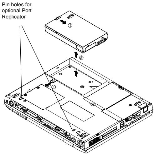
To insert battery, reverse the steps above.
Follow these steps to remove the battery pack:
- Press the handle to the down-left directions as shown by arrow 1. At the same time, press another handle to down-right direction as shown by arrow 1.
- Lift the battery pack up as shown by arrow 2.
Chapter 7 Memory
Your notebook is equipped with a highly configurable memory sub-unit. Industry standard SDRAM S.O. DIMM memory modules, 32MB/64/128MB, are available for memory upgrade from 32MB up to 256MB. There are two memory sockets: both on the bottom side of system board. The table below illustrates some of the most popular way that system memory can be configured.
| Total Memory | Bank A | Bank B |
| 32 MB | 32 MB | None |
| 64 MB | 32 MB | 32 MB |
| 64 MB | None | |
| 96 MB | 32 MB | 64 MB |
| 64 MB | 32 MB | |
| 128 MB | 64 MB | 64 MB |
| 256 MB | 128 MB | 128 MB |
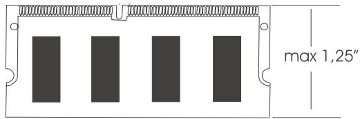
SDRAM S.O. DIMM Memory Module
7.1 Inserting/Removing Memory Module

The diagram on the left shows where the two memory sockets are located; and how the compartment door is opened.
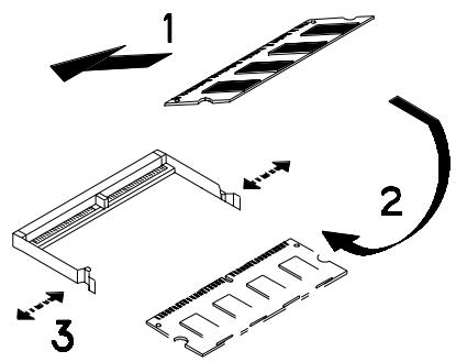
The diagram on the left shows the procedure on how individual memory modules be inserted into its socket:
- When inserting, the module should have an angle of 45° with the motherboard.
- Gently press the module down as shown by arrow 2.
- You will hear a clicking sound when the spring-locks (as shown by arrow 3) bent outward and then bend inward to lock the memory module.
Chapter 8 The CD/DVD-ROM Drive
Depending on the model you have, your notebook is equipped with either a (32x max) CD-ROM drive, or a (8x) DVD-ROM drive.
8.1 The CD/DVD-ROM Drive Panel
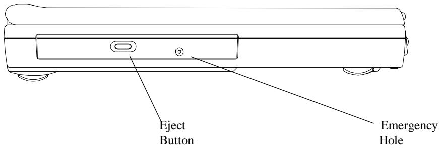
CD/DVD-ROM Drive Panel
Eject Button
Press this button to open or close the disk tray. When the Eject Button is pressed, you will hear a clicking sound and the disk tray will eject.
Emergency Hole
When the notebook is powered off, the Eject Button does not function. To open the CD-ROM or DVD-ROM drive, insert a metal rod (an extended large paper clip with diameter of 1.2mm or less is suitable) into this hole, then push the rod to eject the drive.
Note: Different CD-ROM/DVD-ROM models may have different front panel.
8.2 DISC Loading/Ejection
Disc Loading
- Press the Eject button on the front panel to release the disc tray.
Gently pull the disc tray to its fullest extend. - Place the disc on the tray with its labeled side facing up.
Gently push the disc tray back into the drive.
Disc Ejection
- Press the Eject button on the front panel to release the disc tray.
Gently pull the disc tray to its fullest extend. - Remove the disc from the disc tray, and put it in its protective case.
Gently push the disc tray back into the drive.
8.3 ROM Disc Maintenance
Disc Handling
When removing a disc from its protective case or loading a disc to a drive, hold it by its edges as shown in figure below. NEVER touch the disc's data surface (non labeled side.)
To protect the disc against scratches and dirt, keep it in its protective case when not in use.
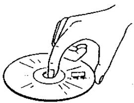
Disc Cleaning
When cleaning the disc, be sure to wipe it from center to edge. Don't wipe the disc in a clockwise/counter clockwise direction. Otherwise, this can damage the disc. Keep the discs away from high temperature and high pressure.
Chapter 9 Peripherals
You can attach a great variety of accessories to your notebook's ports. Each port will be described below.
9.1 PS/2 Keyboard Connector
The notebook includes a 6-pin mini DIN Connector. You can use this connector to attach an external keyboard, or PS/2 mouse.
9.2 Parallel Port
The Parallel Port, also known as the Printer port, uses a standard D-type 25-pin connector. You can connect either a pocket LAN adapter, a printer or any EPP/ECP device to this bi-directional port. This port can be controlled either through BIOS setup or application programs. For detail, refer to Parallel Port in Chapter 11.6.
9.3 COM Port
This COM Port allows external Fax/Modem, serial Mouse, or any other standard RS-232C devices to be connected to your notebook. Since this port is equipped with a high speed buffer (16550 compatible), it supports high-speed serial devices, such as 28.8 Kbps Fax/Modem. This port is a 9-pin D-type standard connector. If your peripheral uses the larger 25-pin connection, ask your local dealer for a 9-pin to 25-pin converter.
9.4 USB Connector
You can attach a great variety of industry standard USB devices, including the nowadays more popular USB mouse, USB keyboard, digital camera, and others.
9.5 VGA Connector
You can attach a VGA or Super VGA Monitor (CRT) to the standard 15-pin D-type VGA Connector. The notebook has the capability to display to the LCD and the external Monitor (CRT) at the same time.
9.6 S-Video Connector
The S-Video port provides video-out connection to television. The most two popular television protocols are NTSC and PAL. Before making the connection to any television, you are advised to set the TV Display field of the Main Setup of the BIOS SETUP. For detail, please refer to Chapter 11.3.
9.7 Audio Jacks
The notebook has four built-in Sound Jacks and one Volume Dial:
Mic In: A microphone can be connected to record speech, music or sounds. Input impedance is 30kohm 100kohm .
Earphone: You can connect your earphones, speakers or tuner system. Output impedance is 8ohm.
9.8 PCMCIA Port
The PCMCIA slot gives you wide variety of connection to different options such as: Fax/Modem, Flash Memory, SCSI Adapter, LAN connection, HDD, and etc.
Even Win95/Win98 has built-in support for PCMCIA cards and will recognize any "plug and play" compatible PCMCIA cards after its insertion. Before inserting a card into the PCMCIA slot, be sure that you have installed the PCMCIA drivers (Chapter 10) that come with the notebook. Otherwise, the notebook may not be able to recognize that a card has been inserted.
9.9 IrDA Port
The IrDA provides infrared transmission rather than via an attached cable. With this feature, you can transfer data without cable attachment. Just place the IrDA Port of the two devices (e.g. a notebook and a printer both equipped with IrDA Port) within line of sight distance (typical: 1.0meter; ± 15° ), and run the IrDA software. And data will be transmitted between the two devices through infrared rays. This IrDA Port has a transmission rate up to 4Mb/s baud.
9.10 Fax Port
The Fax/Modem Port uses RJ11 connector that lets you connect your notebook to the public telephone network for various applications such as: internet, fax machine emulation, and telephone answering machine functions.
9.11 Ethernet LAN Port
The Ethernet LAN Port uses RJ45 connector that lets you connect your notebook to the LAN (Local Area Network).
9.12 IEEE 1394 Port
You can connect the system to equipment that supports the IEEE 1394 industry standard interface.
Chapter 10 The CD-ROM Disc
This notebook is designed to support the latest operating systems which include Windows 98™, Windows NT 4.0™, Windows 2000™. The CD-ROM Disc inside your notebook package contains utilities, drivers, and programs for DOS and different Windows operating systems.
10.1 DOS Utilities and Drivers
The following DOS Utilities are located in the directory "DOS" of the CD-ROM Disc:
- System BIOS Flash Utility
Keyboard Controller (KBC) Flash Utility
"Save-To-File" File Creation Utility
CD-ROM Driver
DVD-ROM Driver - Touchpad Driver
On detail on how to run these utilities, please refer to the respective **.doc" files.
The "Save-To-File" file
In order for the system to be able to perform the "Save-To-File", the "Save-To-File" File needs to be created first. For detail on how the Save-To-File (hibernation) can be activated, refer to Chapter 6.6 and Chapter 11.6. When being activated, the Save-To-File would actually save all the memory settings (system memory, video memory, and system status) to this file. When this file is being created, it will take up contiguous sectors in the HDD whose size would equal to the sum of the system memory, and video memory plus some overhead. Therefore, if you have just upgraded your system memory, you are requested to remove your old Save-To-File File, and then re-create a new one.
10.2 Windows 98 Drivers and Applications
At the time of this manual is written, the following Windows 98 Drivers and applications are available:
Audio Driver
Video Driver
- Touchpad Driver
Modem Driver
DVD Player Application
- Combo Modem Driver
- Combo LAN Driver
- SpeedStep Driver
These drivers are located in the directory "WIN98" of the CD-ROM disc. On detail on how to run these utilities, please refer to the respective *.doc" files.
10.3 Windows NT 4.0 Drivers and Applications
At the time of this manual is written, the following Windows NT 4.0 Drivers and applications are available:
Video Driver
Audio Driver
- Touchpad Driver
Modem Driver
- Combo Modem Driver
- Combo LAN Driver
The Windows NT 4.0 drivers are located in the directory "NT40" of the CD-ROM disc. On detail on how to run these utilities, please refer to the respective *.doc" files.
10.4 Windows 2000 Drivers and Applications
At the time of this manual is written, the following Windows 2000 Drivers and applications are available:
Video Driver
Audio Driver
- Touchpad Driver
Modem Driver
- Combo Modem Driver
- Combo LAN Driver
The Windows 2000 drivers are located in the directory "Win2000" of the CD-ROM disc. On detail on how to run these utilities, please refer to the respective "*.\doc" files.
This page is left blank intentionally.
Chapter 11 Configuring Your System
11.1 Configuration Software
The notebook can easily be configured to suit your personal needs. The built-in SETUP program allows you to setup standard and advanced parameters as well as the Power Management Features. The information is stored in a battery-backed CMOS memory; so when the power is turned off, your setup is retained. This Configuration Software is sometimes refer to as CMOS Setup, BIOS Setup, or simply the SETUP.
Note: The SETUP can only be activated by pressing <F2> during system boot-up.
You are requested to perform the following one-time procedure immediately after you have upgraded/reprogrammed your BIOS:
- Press <F2> during system boot-up to get into the SETUP.
- Choose Auto Configuration with Defaults.
- Press Enter, and then select "Y" followed by Enter.
- Choose Save Settings and Exit, then Enter.
Answer "Y" followed by Enter. - The system will boot-up automatically. Press <F2> during system boot-up to get into the SETUP.
Now, you can customize the BIOS for your personal needs.
For detail on the BIOS SETUP, read on.
Note: For information on the BIOS upgrade, contact your local notebook dealer.
11.2 Running the Setup Utility
You will be greeted by this screen when you enter the SETUP Utility.
| AMIBIOS HIFLEX ENGLISH SETUP - VERSION 1.19 (C)2000 American Megatrends, Inc. All Rights Reserved |
| BIOS Revision 700A_A0x |
| Standard CMOS Setup |
| Advanced CMOS Setup |
| System Security Setup |
| Power Management Setup |
| Boot Device Setup |
| Peripheral Setup |
| Auto Configuration with Defaults |
| Save Settings and Exit |
| Exit Without Saving |
| Standard CMOS setup for changing time, date, hard disk type, etc. ESC: Exit ↑↓: Sel F3/F4:Color F10:Save & Exit |
The above display screen will be referred to as Setup Entry Screen. Detail on the above major sub-menus (options) will be described on the following pages.
Movement within the SETUP utility
To move between the different item fields or to move between the sub-menus, use the arrow keys , , ← , and → . To change the value of a field press the PgUp and PgDn keys. When you select one item, that item will be highlighted (in gray background) and a brief explanation will be displayed the near bottom or on the right side of the screen. The followings are some of the most commonly used keys:
- Pressing F3 , F4 will change the color of the screen.
- Pressing <F10> will save changes on settings and exit.
- Pressing [Esc] will get you to the Setup Entry Screen if you are in the sub-menu. If you are already in the Setup Entry Screen, pressing [Esc] will allow you to exit the SETUP utility.
11.3 Standard CMOS Setup
You will be greeted by this screen when you enter the Standard CMOS Setup Menu:
| AMIBIOS SETUP - STANDARD CMOS SETUP (C)2000 American Megatrends, Inc. All Rights Reserved | |
| Date(mm/dd/yyyy): Sat Nov 06, 1999 | Base Memory: 64 MB |
| Time(hh/mm/ss): 11:13:47 | |
| Floppy Drive A: 1.44 MB 3½ | |
| LBA Blk PIO 32Bit | |
| Type Size Cyln Head Wpcom Sec Mode Mode Mode | |
| Pri Master: Auto 11513 | On On Auto On |
| Sec Master: Auto CD/DVD | On Off Auto On |
| Boot Sector Virus Protection | Disabled |
| Month: Jan - Dec | ESC: Exit ↑↓: Sel |
| Day: 01 - 31 | PgUp/PgDn: Modify |
| Year: 1901 - 2099 | F3/F4: Color |
Date and Time:
Use the arrow keys ← and → to move among these fields to modify the settings. Use PgUp and PgDn keys to modify settings.
Floppy Drive A:
There are two options to this field: 1.44 MB 31/2 , and Not Installed. In general, you should choose 1.44 MB 31/2 .
Pri Master, and 32Bit Mode:
For Pri Master in general, you should choose the default value "Auto" to let the system automatically detect the IDE device you have in the system. For better performance, you should choose On for 32 Bit Mode option.
Sec Master and 32 Bit Mode:
For Sec Master, you should choose the default value "Auto" to let the system automatically detect the DVD-ROM drive you have in the system. For better performance, you should choose On for 32 Bit Mode option.
Boot Sector Virus Protect:
There are two options to this field: Disabled, and Enabled. You should choose Enabled so as to protect the system's boot sector from virus infection.
11.4 Advanced CMOS Setup
You will be greeted by this screen when you enter the Advanced CMOS Setup Menu:
| AMIBIOS SETUP - ADVANCED CMOS SETUP (C)2000 American Megatrends, Inc. All Rights Reserved | |
| Video out Type NTSC LCD Panel View Expansion On Internal Mouse Enabled Suspend Warning Tone Enabled Intel(R)SpeedStep(TM)Technology Automatic | Select the appropriate Video Standard for your country. ‘NTSC’ is for USA/Japan, and ‘PAL’ is for Europe. ESC: Exit ↑↓: Sel PgUp/PgDn: Modify F3/F4: Color |
Video Out Type:
There are two options to this field: NTSC, and PAL. Depending on the type of television set used in your country, choose either NTSC or PAL. NTSC is commonly used in North America and Japan. And PAL is the most accepted standard in the European countries.
LCD Panel View Expansion:
There are two options to this field: On and Off. For example, if this field is set to Off and when the system resolution is set to 640x480, the display content would not be a full panel display. However, if this field is set to On and when the system resolution is set to 640x480, the display content would be expanded to full panel display. However, the quality of graphic/text of the expanded display may be adversely affected.
Internal Mouse:
There are two options to this field: Enabled, and Disabled. In general, you should choose Enabled.
Suspend Warning Tone:
There are two options to this field: Enabled, and Disabled. In general, you should choose Enabled to allow system to issue Suspend Warning Tone during/before entering suspend.
Intel (R) SpeedStep (TM) Technology:
There are three options to this field: Automatic, Disabled, and Battery opt.. This is a state-of-the-art power rationing feature supported by Intel's latest SpeedStep CPU (Pentium III 600/650/700/750MHz) whereby the CPU would be able to switch between full speed and optimized, as defined below:
| Intel CPU Type | full speed | optimized speed |
| Pentium III SpeedStep 600MHz | 600MHz | 500MHz |
| Pentium III SpeedStep 650MHz | 650MHz | 500MHz |
| Pentium III SpeedStep 700MHz | 700MHz | 550MHz |
| Pentium III SpeedStep 750MHz | 750MHz | 600MHz |
Depending on how the system is powered, either by AC source or by battery pack, the SpeedStep CPU would switch its CPU speed as according to the three options listed below:
| Options | Powered by AC Adapter | Powered by Battery Pack |
| Automatic | full speed | optimized speed |
| Disabled | optimized speed | optimized speed |
| Battery Opt. | optimized speed | optimized speed |
11.5 System Security Setup
You will be greeted by this screen when you enter the System Security Setup Menu:
| AMIBIOS SETUP - SYSTEM SECURITY SETUP (C)2000 American Megatrends, Inc. All Rights Reserved | ||
| Change Supervisor Password | Press Enter | If supervisor password is entered, the system requires the supervisor password to enter this Setup utility. Pressing Ctrl-Alt-Backspace locks up the keyboard until the password is entered. The Cap Lock and Scroll Lock LEDs will flash in sequence while waiting for the user to enter a password. |
| Change User Password | Press Enter | |
| Boot Password Required | No | |
| Resume Password Required | No | |
| ESC: Exit ↑↓: Sel PgUp/PgDn: Modify F3/F4: Color | ||
Change Supervisor Password:
The Supervisor Password provides access:
to the SETUP Utility.
to the system during system boot up, if Boot Password (refer to below in Chapter 11.5) is enabled.
- during resume from suspend (see Suspend Option in Chapter 11.6), if the Resume Password (refer to below in Chapter 11.5) is enabled.
to unlock the keyboard, if keyboard is locked by pressing Ctrl-Alt-Backspace.
Change User Password:
The User Password provides access:
to the system during system boot up, if Boot Password (refer to below in Chapter 11.5) is enabled.
- during resume from suspend (see Suspend Option in Chapter 11.6), if the Resume Password (refer to below in Chapter 11.5) is enabled.
to unlock the keyboard, if keyboard is locked by pressing Ctrl-Alt-Backspace.
Boot Password Required:
There are two options to this field: No, and Yes. If this option is set to Yes and when Supervisor Password and/or User Password have been set, system would prompt for password during system boot up. In order to access the system, you need to enter either the Supervisor Password or the User Password.
Resume Password Required:
This option can be set only if the Boot Password is enabled. There are two options to this field: No, and Yes. If this option is set to Yes and when Supervisor Password and/or User Password have been set, system would prompt for password when resuming from suspend (see Suspend Option in Chapter 11.6). In order to access the system, you need to enter either the Supervisor Password or the User Password.
11.6 Power Management Setup
You will be greeted by this screen when you enter the Power Management Setup Menu:
| AMIBIOS SETUP - POWER MANAGEMENT SETUP (C)2000 American Megatrends, Inc. All Rights Reserved | ||
| Power Switch | Power Button | Use 'Power Button' to power the system On or Off. Use 'Sleep Button' to enter or resume from suspend mode. |
| Power Management Under AC Power Off | ||
| Power Saving Level | Off | |
| Hard Disk Time-out | Off | |
| Video Time-out | Off | |
| Standby Time-out | Off | |
| Auto Suspend Time-out | Off | |
| LCD Suspend | Disabled | |
| Suspend Option | Suspend | |
| Auto Save To File | Disabled | |
| Wake Up Alarm | Disabled | |
| Resume Alarm Time | Off | |
| ESC: Exit ↑↓: Sel PgUp/PgDn: Modify F3/F4: Color | ||
Power Switch:
There are two options to this field: Power Button, and Sleep Button. This field is for programming the Power Switch (see Chapter 2.6 and then Chapter 2.2). If this field is set to Power Button, the Power Switch would behave as a normal power On/Off button. If this field is set to Sleep Button, there are four scenarios:
- If the Power Switch is pressed continuously for 4 seconds or more, the system would power off.
- If the Power Switch is pressed for less than 4 seconds, the Suspend Option is set to Suspend (also referred to as STR), and when system is operating: system would perform Suspend-To-RAM; whereby system can be woke up by Power Switch. This scenario is applicable only to WinNT's and Win98's APM mode.
- If the Power Switch is pressed for less than 4 seconds, the Suspend Option is set to STF, and when system is operating: system would perform Suspend-To-File (STF) or
sometimes referred to as hibernate/hibernation; whereby system would save its system memory and status into a system file. System can be woke up by the Power Switch. This scenario is applicable only to WinNT's and Win98's APM mode.
- If the Power Switch is pressed for less than 4 seconds when system is either in STR or STF mode, system would wake up from one of these two suspend modes. Waking up from STR is immediate. Waking up from STF take a little while. System appears to be powered off when it is in STF mode.
Note:
For exact location of Power Switch, refer to diagram in Chapter 2.2. For detail on Suspend Option, refer to the Suspend Option below in Chapter 11.6. For detail on Suspend (also referred to as STR), STF and APM vs ACPI, refer to Chapter 6.6 and Chapter 6.7.
Note:
In ACPI operating systems (Windows 98 ACPI, and Windows 2000), the type of suspend the system would enter is determined and overridden by the related settings in the respective operating systems.
Power Management Under AC Power:
There are two options to this field: Off and On. When you have access to AC power, power management is not vitally important. For this reason, you might like to choose Off; by which all the "time-out" power management functions below would not be effective, if your system is powered by the AC power source. When On is chosen, the Power Management level is the same whether the AC power is connected, or not.
Power Saving Level:
There are four options to this field: Off, Custom, High Perform, and Longest Life. The setting of this field control the settings of the fields below: CPU Speed Control, Hard Disk Time-out, Video Time-out, Standby Time-out, and Auto Suspend Time-out.
- Setting this field to Off effectively sets these time-outs to Off as well.
- The Longest Life effectively set these time-outs to shorter time durations than those set by High Perform. Thus when Longest Perform is chosen, system is able operate without AC power source much longer than when is High Perform chosen.
- Custom provides you a power management template. You can use this template as a basis to customize your CPU- time-outs scheme.
If your system is running on APM (Advanced Power Management) mode, you can switch between these 4 Power Saving Levels by pressing Fn < F7 . The advantage of using Fn < F7 is that you do not have to go through the trouble of entering the SETUP to switch between these levels. And Fn < F7 is a cyclical switch that allows you to loop back to your original setting by pressing Fn < F7 repeatedly. You would hear the following beeps when you enter the levels below:
| Power Saving Levels | Beep Descriptions |
| Off | 1 beep |
| Custom | 2_beeps |
| High Perform | 3_beeps |
| Longest Life | 4_beeps |
For more information on APM and ACPI modes, please refer to Chapter 6.7.
Hard Disk Time-out:
You would be able to set this field only when the Power Saving Level is set to Custom. Select the time duration of which the hard disk would idle before spinning down. The amount of time for the hard disk to spin-up to its normal operating speed depends on its manufacturer and is around 3~5 seconds. If you are a performance-conscious user, you may like to set this field to Off.
Video Time-out:
You would be able to set this field only when the Power Saving Level is set to Custom. Select the time duration of which both the keyboard and mouse have no activity before turning off the LCD display. Any activities from keyboard or mouse would turn on the display immediately.
Standby Time-out:
You would be able to set this field only when the Power Saving Level is set to Custom. Select the time duration of which the system has no activity before entering Standby. In Standby mode, the LCD display would be turned off. Any activities from keyboard or mouse would resume the system to its normal operation immediately.
Auto Suspend Time-out:
You would be able to set this field only when the Power Saving Level is set to Custom. Select the time duration of which the system has no activity before entering the type of
suspend mode, as determined by the setting in Suspend Option below. Suspend Option has two options: Suspend (also referred to as STR) and, STF.
LCD Suspend:
There are two options to this field: Disabled, and Enabled. If this field is set to Enabled, system would enter the type of suspend mode (as determined by the setting in Suspend Option), when the LCD display is closed. Suspend Option has two options: Suspend (also referred to as STR) and, STF.
Suspend Option:
There are two options to this field: Suspend, and STF. Suspend can also be referred to as Suspend-To-RAM (STR). STF stands for Suspend-To-File, and can also be referred to as hibernate/hibernation. STF provides as much as a power saving as if the system had been powered off. While STR provides less power saving than STF, STR saves more power than when the system is in Standby mode. The way to trigger a resumption from STR and STF are the same; by pressing the Power Switch. However resuming from STF takes a significantly more time than resuming from STR.
Auto Save To File:
There are two options to this field: Disabled, and Enabled. With this field set to Enabled, system would automatically enter Save-To-File (STF) mode after the system has been in Suspend-To-RAM (STR) mode continuously for 30 minutes.
Wake Up Alarm/Resume Alarm Time:
Wake Up Alarm and Resume Alarm Time work hand-in-hand with one another. There are two options to Wake Up Alarm: Disabled, and Enabled. You would be able to set the Resume Alarm Time only if Wake Up Alarm has been set to Enabled. For example with these two fields set to Enabled and 8:00AM respectively, the system would be able to wake (resume) itself from Suspend (also referred to as STR) or STF to normal operation at 8:00AM. The amount of time required to wake up from STF is somewhat longer than STR.
Note: The time-out settings in the Power Management Setup is not applicable to ACPI OS's: Win98 ACPI and Win 2000.
11.7 Boot Device Setup
You will be greeted by this screen when you enter the Boot Device Setup Menu:
| AMIBIOS SETUP - BOOT DEVICE SETUP (C)2000 American Megatrends, Inc. All Rights Reserved | ||
| Quick Boot | Enabled | "Enabled" allows the system to skip part of test during system is booting. |
| Silent Boot | Enabled | |
| Boot Display Device | Simul. Mode | |
| BootUp Num-Lock | Off | |
| 1stBoot Device | CD/DVD | |
| 2ndBoot Device | Floppy | |
| 3rdBoot Device | 1stIDE-HDD | |
| Try Other Boot Devices | Yes | |
| ESC: Exit ↑↓: Sel PgUp/PgDn: Modify F3/F4: Color | ||
Quick Boot:
There are two options to this field, Enabled and Disabled. Enabled allows the system to skip part of the Power On Self Test (POST) during system boot up.
Silent Boot:
There are three options to this field, Enabled, Disable, and Black. Enabled allows the system to display the MAXDATA logo screen during system boot up. Otherwise, a "black" screen would be displayed. This "black" screen would last for about 20 seconds, and would appear as if the system has no response. The Disable screen lists the systems BIOS information.
Boot Display Device:
There are three options to this field: Simul. Mode, LCD Only, and CRT Only. As names of these options imply, LCD Only and CRT Only have the system boot up with the designated display device "only". When Simul. Mode is chosen, both the LCD and CRT would be displayed "simultaneously" if a CRT is connected to the system.
BootUp Num-Lock:
There are two options to this field: Off, and On. If On is selected, system would automatically enable Num-Lock during System boot up.
1st Boot Device:
There are five options to this field: Disabled, IDE HDD, Floppy, CD/DVD, and Network. In general, you should use CD/DVD as the system's first choice of boot device.
2nd Boot Device:
There are four options to this field: Disabled, IDE HDD, Floppy, and CD/DVD. In general, you should use Floppy as the system's second choice of boot device.
3rd Boot Device:
There are four options to this field: Disabled, IDE HDD, Floppy, and CD/DVD. In general, you should use IDE HDD as the system's third choice of boot device.
Try Other Boot Devices:
There are two options to this field: Yes, and No. If Yes has been selected and all 3 Boot Devices above fail to boot the system, system would attempt to boot from other devices: such as through LAN card, and PCMCIA SCSI devices.
11.8 Peripheral Setup
You will be greeted by this screen when you enter the Peripheral Setup Menu:
| AMIBIOS SETUP - PERIPHERAL SETUP (C) 1998 American Megatrends, Inc. All Rights Reserved | ||
| Internal Hard Drive | Enabled | Available Options: Enable Disabled |
| OnBoard Serial Port1 | Auto | |
| OnBoard Parallel Port1 | ECP | |
| ESC: Exit ↑↓: Sel | ||
Internal Hard Drive:
There are two options to this field: Enable, and Disabled. In general, you should choose Enabled.
OnBoard Serial Port1:
There are two options to this field: Auto, and Disabled. In general, you should choose Auto.
OnBoard Parallel Port1:
There are three options to this field: Normal, EPP and ECP. In general, you should choose ECP.
11.9 Auto Configuration With Defaults
This mini menu allows you to reload the SETUP to its preset default values.
Warning: After loading the COMS to its preset values, the previous changes you had made and saved in SETUP will be lost.
11.10 Save Settings and Exit
This mini menu allows you to save the changes you have just made before exiting the SETUP. If you have made changes to the SETUP settings, you should use this option. Otherwise, the changes would be lost.
11.11 Exit Without Saving
This mini menu allows you to exit the SETUP without saving the changes you have just made. If you have made changes to the SETUP settings and you want to discard such changes, you should use this option.
Appendix A - Connectors and Pin Assignments
A.1 Keyboard or PS/2 Mouse Connector
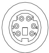
| PIN | Assignment | PIN | Assignment |
| 1 | Keyboard data | 4 | +5V |
| 2 | No Connection | 5 | Keyboard clock |
| 3 | Ground | 6 | No connection |
A.2 Printer Port Connector
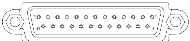
| PIN | Assignment | PIN | Assignment | PIN | Assignment |
| 1 | STROBE # | 10 | Acknowledgment | 19 | GROUND |
| 2 | DATA 0 | 11 | BUSY | 20 | GROUND |
| 3 | DATA 1 | 12 | Paper Empty | 21 | GROUND |
| 4 | DATA 2 | 13 | Selected | 22 | GROUND |
| 5 | DATA 3 | 14 | Auto Feed # | 23 | GROUND |
| 6 | DATA 4 | 15 | ERROR # | 24 | GROUND |
| 7 | DATA 5 | 16 | INITIALIZE | 25 | GROUND |
| 8 | DATA 6 | 17 | SLIN # | ||
| 9 | DATA 7 | 18 | GROUND |
A.3 Communication Port Connector
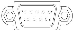
| PIN | Assignment | PIN | Assignment | PIN | Assignment |
| 1 | Carry detect | 4 | Data Terminal | 7 | Req. to send |
| 2 | Received data | 5 | GROUND | 8 | Clear to send |
| 3 | Transmit data | 6 | Data Send | 9 | Ring indicator |
A.4 USB Port Connector
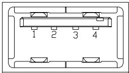
| PIN | Assignment | PIN | Assignment |
| 1 | +5VS | 2 | USBP0- |
| 3 | USBP0+ | 4 | GND |
A.5 VGA Monitor Connector
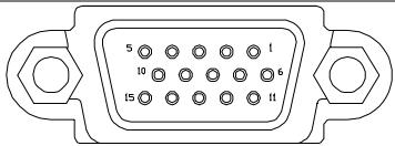
| PIN | Assignment | PIN | Assignment | PIN | Assignment |
| 1 | RED | 6 | GROUND | 11 | N.C. |
| 2 | GREEN | 7 | GROUND | 12 | N.C. |
| 3 | BLUE | 8 | GROUND | 13 | HSYNC |
| 4 | N.C. | 9 | N.C. | 14 | VSYNC |
| 5 | GROUND | 10 | GROUND | 15 | N.C. |
A.6 Modem/Phone Connector (RJ11)
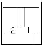
| PIN | Assignment |
| 1 | TIP |
| 2 | RING |
A.7 LAN Connector (RJ45)
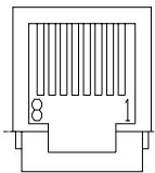
| PIN | Assignment | PIN | Assignment |
| 1 | TX+ | 5 | GND |
| 2 | TX- | 6 | RX- |
| 3 | RX+ | 7 | GND |
| 4 | GND | 8 | GND |
A.8 S-Video Connector
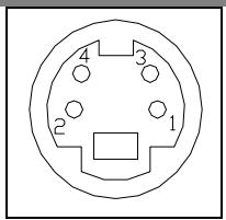
| PIN | Assignment | PIN | Assignment |
| 1 | GND | 3 | Y |
| 2 | GND | 4 | C |
A.9 IEEE 1394 Connector
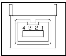
| PIN | Assignment | PIN | Assignment |
| 1 | TPB0 | 3 | TPA0 |
| 2 | TPB0# | 4 | TPA0# |
Appendix B - Hot-Keys
To use the Hot Keys, press and hold down <Fn> together with the key described below (depends on the operation system):

Internet Mail Hot Key
User can program this Hot Key to activate an Internet Mail application.

Mail Hot Key
User can program this Hot Key to active a Mail application.

Audio CD Hot Key
User can program this Hot Key to active an Audio CD application.

Suspend-To-RAM Hot Key
Press this Hot Key to let system enter Suspend-To-RAM mode. For more detail on Suspend-To-RAM, refer to Chapter 6.6, and Chapter 11.6.

Press this Hot Key to let system enter Suspend-To-Disk mode. For more detail on Suspend-To-Disk, refer to Chapter 6.6, and Chapter 11.6.

LCD/CRT Hot Key
Press this Hot Key to switch between LCD only, CRT only, LCD/CRT simultaneous, and TV only displays.

Contrast Decrease Hot Key
Press this Hot Key to decrease the contrast of the DSTN (LCD) display.

Contrast Increase Hot Key
Press this Hot Key to increase the contrast of the DSTN (LCD) display.

Brightness Decrease Hot Key
Press this Hot Key to decrease the brightness of the LCD display.

Brightness Increase Hot Key
Press this Hot Key to increase the brightness of the LCD display.

Volume Decrease Hot Key
Press this Hot Key to decrease volume.

Volume Increase Hot Key
Press this Hot Key to increase volume.
Appendix C - Glossary
ACPI Advanced Configuration Power Interface. A latest power management standard jointly developed by Microsoft, Intel, and Toshiba.
APM Advanced Power Management. An operating and application level of power management. Your notebook is fully compatible with this standard.
BIOS Basic Input Output System. In the manual, we refer the BIOS as Setup. To change the BIOS, press
BIT A binary digit. The smallest unit of measure used in a computer. It takes 8 bits to make a byte.
BOOT To load a program or operating system into the memory to start the computer.
BUS Electrical circuit within the system used to transmit data from one device to another. BYTE 8 bits. 1,024 Bytes is called 1KB. A million Bytes is called a megabyte, or MB.
CAcHc A place in the CPU where the computer can temporarily store data to avoid accessing the HDD and FDD drives. There is also an external onboard 512KB fast write-through cache in your notebook to improve performance.
CD-ROM Compact Disc-Read Only Memory. It stores up to 640MB of information per disc.
CMOS Complementary Metal-Oxide Semi-conductor. This low-power consumption module is capable of keeping the BIOS setup even the notebook is powered off.
CPU Central Processing Unit. Your notebook is compatible with Pentium® CPUs.
CRT Cathode Ray Tube. Another name is for an external monitor.
DMA Direct Memory Access. Your notebook supports two DMA's and both can be used.
DOS Disk Operating System.
DRAM Dynamic Random Access Memory, also known as RAM.
DSTN Dualscan Twist Neu-matic. Double the performance compared to STN, but less than TFT. DSTN also known as Dual-Scan color.
ECP Extended Capabilities Port. This bi-directional communication mode is faster than the EPP, and SPP mode; and allows the system to connect up to seven devices through parallel interface.
EPP Enhanced Parallel Port. This bi-directional communication mode is faster than the SPP, but slower than the ECP mode.
FDD Floppy Diskette Drive. You can use any 3.5" diskette that has a storage capacity of 1.44MB or 720KB.
FORMAT Preparing a disk (floppy or HDD) for use in an OS. Formatting erases all the information on the disk.
HDD Hard Disk Drive.
HIBERNATION mode, or Suspend To Disk mode, saves all memory, so system can re-start at where Suspend To Disk was invoked.
IDE Integrated (or Intelligent) Drive Electronics. Standard HDD type used in notebooks.
I/O Input/Output, used for different kind of communications between devices.
IRQ Interrupt Request, every device has an IRQ number. If two devices share the same number, there will be a conflict and then none of the devices will work.
I rDA Infrared Data Association, a standard for infrared ray data transmission.
ISA A standard for 8 and 16-bit expansion cards. This standard is also referred as AT-bus. The speed on the bus is 8MHz
KB Kilo Byte (1024 bytes).
LAN Local Area Network. A group of computers connected together to share information and resources. There are many different standards for LAN: ETHERNET, Token Ring, etc...
LCD Liquid Crystal Display. A common name for your notebook's screen.
Local-Bus The speed of Local-Bus is vastly superior than the AT-Bus (8MHz).
MB Mega Byte (1 million bytes).
Mouse A pointing device to move your cursor under certain software, such as Windows, and OS/2.
MPEG A stands for Motion Picture Experts Group. It supports real-time, full-motion video, audio data compression and decompression.
OS Operating System. There are many different types like: MS-DOS, Windows, OS/2, UNIX, etc...
PARTITION A logical unit created on the HDD, which is seen to the OS as a separate drive.
PIXEL Image elements (small points), that compose a screen image.
PCMCIA Personal Computer Memory Card International Association. A small credit-card size accessory that can contain memory, Fax/Modem, SCSI adapter, etc... Also known as PC card.
POST Power-On-Self-Test. Every-time you power on the notebook,
POST runs many different tests to insure the system will operating properly.
RAM Random Access Memory. See DRAM.
ROM Read Only Memory. This memory contains the BIOS where all the information about your notebook is stored.
SPP Standard Parallel Port. This bi-directional communication mode is slower than the EPP and ECP modes. Also see EPP and ECP.
TFT Thin Film Transistor. The speed and resolution is better than the DSTN display. TFT is also known as Active Matrix.
TouchPAD A pointing device that uses your finger to glide the cursor.
UART Universal Asynchronous Receiver/Transmitter. The UART is compatible to NS16550. Used for high speed serial port connections.
VGA Video Graphics Array. A standard for 640x480 resolution. Most computers have higher resolution: 800x600 or 1024x768 (SVGA).
This page is left blank intentionally.
Appendix D - Port Replicator
The Port Replicator is a convenient device if you do travel a lot with your notebook, and yet you like to establish quick connections to your host of external devices; whether you be at home, or in the office. In addition, the Port Replicator provides one more connector, the game port, that is not available to your standard notebook.
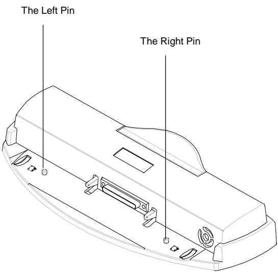
There are two pins on the Port Replicator. The purpose of these pins is to station the notebook onto the Port Replicator by pegging into the two pin holes on the back of the notebook. For exact location of the two pin holes, refer to diagram in Chapter 6.8.
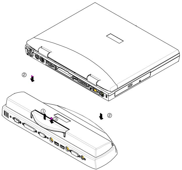
Follow the steps below to engage the Port Replicator:
- Lift up the handle as shown by arrow 1.
- Put the notebook system down as shown by arrow 2. Make sure the 2 pins are pegged into the pin holes that are located on the chassis of the system unit.
- Press the handle down as shown by arrow 3.
Reverse the steps above to disengage the Port Replicator.
Appendix E - Other Keyboards
The following keyboards are also available to your notebook:
French Keyboard
German Keyboard
Swiss German Keyboard
UK Keyboard
US International Keyboard
Please consult your dealer on the above keyboards.
The page is left blank intentionally.
Appendix F - Error Log
Your Name
Phone # :
Fax # :
Tested System Name:
S/N: Date:200- -
CPU (K6): 300MHz
333MHz 350MHz
□380MHz □400MHz
Memory: 32MB
64MB
□128MB
256MB
Display: TFT
DSTN
LCD+CRT
□
HDD: MB
Manufacturer:
□
Model
Revisions: BIOS
VGA
PCMCIA
□ Utility
□
OS: Win98
WinNT
Win2K
WinME
□
Peripherals Attached:
Sound Card: Enabled
□ DMA
□IRQ
Ext. Micro.
□
□ Internal Fax/Modem
□ Mouse
□ Printer
PCMCIA card:
Network
Fax/Modem
Memory
4
PCMCIA DMA
Type:
Name:
Revision:
IRQ
PCMCIA Card DMA
Type:
Name:
Revision:
IRQ
Software where problem occurs:
Name:
Rev.:
Error Message:
Following pages attached:
- Config.sys
Autoexec.bat
屏幕 copies or listings)
Power Management Setup
Advanced BIOS setup
If you have any problems with your notebook, especially with software or hardware compatibility we would like to hear from you so we can maintain 100% compatibility. Therefore if you find any problem, please fill-out this report and fax to your local dealer for technical support.
If you have tried many different settings or configurations, like IRQ, DMA, LCD or CRT, mark all of them so that we can repeat the problem under the same configuration(s).
Attach another page with detail description of your problem or use the backside.
Your cooperation is most appreciated!
Problem description:
Appendix G - Agency Regulatory Notices
G.1 Safety Instructions

CAUTION: Please read these safety instructions carefully.

CAUTION: Please keep this User's Manual for future reference.

CAUTION: Please disconnect this equipment from AC outlet before cleaning. DO NOT use liquid or sprayed detergent for cleaning. Use a clean moistened cloth.

CAUTION: The wall socket used should be positioned near the equipment and should be easily accessible.

CAUTION: Please keep this equipment free from humidity.

CAUTION: Place the equipment on a reliable surface at all times. A drop or fall can cause severe damage.
| WARNING: The openings on the enclosure are for air ventilation and is meant to protect the equipment from overheating. DO NOT COVER THE VENTILATION OPENINGS. | |
| CAUTION: Verify the voltage of the power source before connecting the unit to any power outlet. | |
| WARNING: DO NOT step on or place anything over the power cord. | |
| CAUTION: All cautions and warnings on the equipment should be noted. | |
| WARNING: If the equipment is not used for a long period of time, disconnect the equipment from the power source to avoid damage from power spikes. | |
| WARNING: NEVER pour any liquid into any openings; a fire or electrical shock is possible. | |
| WARNING: For safety reasons; other than pre-designated ports and doors, the equipment should be opened only by qualified service personnel. | |
| ! | CAUTION: If one of the following situations should arise, the equipment should be checked by an authorized technician: a. The power cord or plug is damaged. b. Liquid has penetrated into the equipment. c. The equipment has been exposed to excessive moisture. d. The equipment does not work well or you can not get it to work according to user's manual. e. The equipment has been dropped or damaged. f. The equipment has obvious signs of breakage. |
| ! | CAUTION: DO NOT LEAVE THIS EQUIPMENT IN TEMPERATURES BELOW -20°C(-4°F) OR ABOVE 60°C(140°F). IT MAY CAUSE DAMAGE TO THE EQUIPMENT. |
| ! | WARNING: To reduce the risk of electrical shock, always ensure that the modem line is disconnected from the telephone network while installing your system or when opening the equipment's enclosure. |
| ! | WARNING: Never install modem/telephone wiring during a lightning storm. |
| ! | WARNING: Never install modem/telephone jacks in wet locations unless the jack is specially designed for wet locations. |
| ! | WARNING: Never touch un-insulated modem/telephone wires or terminals unless the modem/telephone line has been disconnected at the network interface. |
| ! | CAUTION: Use caution when installing or modifying modem/telephone lines. |

WARNING: Avoid using a modem/telephone (other than a cordless type) during an electrical storm. There may be a remote risk of electric shock from lighting.

WARNING: THE CD-ROM/DVD-ROM IN THIS NOTEBOOK EMPLOYS A LASER SYSTEM.
a. To ensure proper use of this product, please read the relevant instructions carefully and retain for future reference.
b. Should the unit ever require maintenance, contact your local dealer.
c. Use of controls, adjustments or the performance of procedures other than those specified may result in hazardous radiation exposure.
d. To prevent direct exposure to Laser Beam, do no try to open the enclosure.

CAUTION: The internal CD-ROM/DVD-ROM drive is classified as a CLASS 1 LASER PRODUCT. Label is located on the outside of the CD-ROM/DVD-ROM drive with the following wordings:
CLASS 1 LASER PRODUCT KLASSE 1 LASER PRODUKT

WARNING: Danger of explosion if battery is incorrectly replaced. Replace only with the same or equivalent type recommended by the manufacturer. Dispose of used batteries according to the manufacturer's instructions.
| WARNING: This computer contains an internal lithium battery-powered real-time circuits. There is a risk of explosion and injury if the battery is incorrectly replaced or handled. Do not attempt to recharge, disassembled, immer in water, or dispose of it in fire. Replacement should be done by your note dealer. | |
| WARNING: Your notebook contains a NiMH or Li-Ion battery pack. There is a risk of fire and chemical burn if the battery pack is handled improperly. Do not disassemble, crush, puncture, short external contact, dispose of in water or file, or expose it to temperature higher than 60°C. | |
| WARNING: Handle the battery pack very carefully. Avoid touching the metal leads on the connector of the battery case. | |
| CAUTION: Use only approved AC Adapter with your notebook. Using the wrong type of AC Adapter may cause serious damage to your notebook. | |
| CAUTION: The AC Adapter can accept a line voltage ranging from 100V to 240V and is compatible with most international power sources. If you are unsure whether your power source is compatible, please contact the local dealer for a assistance. |
G.2 Agency Notice
Declaration of Conformity - United States Only
This device complies with Part 15 of the FCC Rules. Operation is subject to the following two conditions: (1) this device may not caused harmful interference, and (2) this device must accept any interference received, including interference that may cause undesired operation.
Federal Communications Commission Notice
This equipment has been tested and found to comply with the limits for a Class B digital device, pursuant to part 15 of the FCC Rules. These limits are designed to provide reasonable protection against harmful interference in a residential installation. This equipment generates, uses and can radiate radio frequency energy and, if not installed and used in accordance with the instructions, may cause harmful interference to radio communications.
However, there is no guarantee that interference will not occur in a particular installation. If this equipment does cause harmful interference to radio or television reception, which can be determined by turning the equipment off and on, the user is encouraged to try to correct the interference by one or more of the following measures:
Reorient or relocate the receiving antenna.
- Increase the separation between the equipment and receiver.
- Connect the equipment into an outlet on a circuit different from that to which the receiver is connected.
- Consult the dealer or an experienced radio or television technician for help.
Modifications
The FCC requires the user to be notified that any changes or modifications made to this device that are not expressly approved by the manufacturer responsible for compliance may void the user's authority to operate the equipment.
Cables
Connections to this device must be made with shielded cables with metallic RFI/EMI connector hoods to maintain compliance with FCC Rules and Regulations.
Canadian Notice
This Class B digital apparatus meets all requirements of the Canadian Interference-Causing Equipment Regulations.
Avis Canadien
Product with the CE Marking comply with both the EMC Directive (89/336/EEC) and the Low Voltage Directive (73/23/EEC) issued by the Commission of the European Community.
Compliance with these directives implies conformity to the following European Norms:
EN55022 (CISPR 22) Radio Frequency Interference
EN50082-1 (IEC801-1, IEC801-3, IEC801-4)—Electromagnetic Immunity
EN60950 (IEC950)—Product Safety
U.S. Regulations Governing the Use of Modems
This equipment complies with Part 68 of the FCC Rules. On this equipment is a label that contains, among other information, the FCC registration number and Ringer Equivalence Number (REN) for this equipment. You must, upon request, provide this information to your telephone company.
If your telephone equipment causes harm to the telephone network, the Telephone Company may discontinue your service temporarily. If possible, they will notify in advance. But, if advance notice is not practical, you will be notified as soon as possible. You will be informed of your right to file a compliant with the FCC.
Your telephone company may make changes in its facilities, equipment, operations, or procedures that could affect proper operation of your equipment. If they do, you will be notified in advance to give you an opportunity to maintain uninterrupted telephone service.
The FCC prohibits this equipment to be connected to party lines or co-intelligence service.
In the event that this equipment should fail to operate properly, disconnect the equipment from the phone line to determine if it is causing the problem. If the problem is with the equipment, discontinue use and contact your dealer or vendor.
The FCC also requires the transmitter of a FAX transmission be properly identified (per FCC Rules Part 68, Sec 68.381 (C) (3)).
U.K. Modem Compliance Information
This modem is approved by the secretary of state at the Department of Trade and Industry for connection to a single exchange line of the public switched telephone network run by certain licensed public telecommunication operators or system connected there to (Direct exchange lines only, not shared service or 1-1 carrier systems).
This modem is also suitable for connection to Private Automatic Branch Exchange (PABX's) which return secondary proceed indication.
If this modem is to be used with a PBX which has extension wiring owned by BT, connection of the modem the PBX can only be carried out by BT; or by the authorized maintainer of the PBX unless the authorized maintainer has been given 14 days written notice that the connection is to be made by another person; and that period of notification has expired.
This modem is suitable for use only on telephone lines proved with Loop Disconnect or Multi-Frequency Dialing Facilities.
Users of this modem are advised that the approval is for connection to the PSTN via the telephone line interface supplied with it. Connection of a modem to the PSTN by any other means will invalidate the approval.
There is no guarantee of correct working in all circumstances. Any difficulties should be referred to your supplier.
Some network operators require that intended users of their network request permission to connect and for the installation of an appropriate socket.
The Ringer Equivalence Number (REN) of this modem is 1. REN is guide to the maximum number of apparatus that can simultaneously be connected to one telephone line. The REN value of each apparatus is added together, and should not exceed 4. Unless otherwise marked, a telephone is assumed to have a REN of 1.
This modem is only approved for use of the following facilities:
Storage of telephone numbers for retrieval by a predator mined code.
- Detection of initial proceed indication.
Automatic calling/ automatic answering.
- Tone detection.
- Loud-speaking facility.
This modem is not approved for connection to U.K./private speech-band services. This modem does not support an automatic re-dial function. Any other usage will invalidate the approval of your modem, if as a result, it then ceases to confirm to the standards against which approval was granted. The approval of this modem is invalidated if the apparatus us subject to modification in any material way not authorized by the BABT or if it is used with, or connected to external software that have not been formally accepted by BABT.
Ter kennisgeving
| AMIBIOS HIFLEX ENGLISH SETUP - VERSION 1.19 (C)2000 American Megatrends, Inc. All Rights Reserved |
| BIOS Revision 700A_A0x |
| Standard CMOS Setup |
| Advanced CMOS Setup |
| System Security Setup |
| Power Management Setup |
| Boot Device Setup |
| Peripheral Setup |
| Auto Configuration with Defaults |
| Save Settings and Exit |
| Exit Without Saving |
| Standard CMOS setup for changing time, date, hard disk type, etc. ESC: Exit ↑↓: Sel F3/F4:Color F10:Save & Exit |
| AMIBIOS SETUP - ADVANCED CMOS SETUP (C)2000 American Megatrends, Inc. All Rights Reserved | |
| Video out Type NTSCLCD Panel View Expansion OnInternal Mouse EnabledSuspend Warning Tone EnabledIntel(R)SpeedStep(TM)Technology Automatic | Select the appropriate VideoStandard for your country. 'NTSC' isfor USA/Japan, and 'PAL' is forEurope.ESC: Exit ↑↓: SelPgUp/PgDn: ModifyF3/F4: Color |
Video Out Type:
LCD Panel View Expansion:
Suspend Warning Tone:
| AMIBIOS SETUP - SYSTEM SECURITY SETUP (C)2000 American Megatrends, Inc. All Rights Reserved | ||
| Change Supervisor Password | Press Enter | If supervisor password is entered, the system requires the supervisor password to enter this Setup utility. Pressing Ctrl-Alt-Backspace locks up the keyboard until the password is entered. The Cap Lock and Scroll Lock LEDs will flash in sequence while waiting for the user to enter a password. |
| Change User Password | Press Enter | |
| Boot Password Required | No | |
| Resume Password Required | No | |
| ESC: Exit ↑↓: Sel PgUp/PgDn: Modify F3/F4: Color | ||
Change Supervisor Password:
Change User Password:
Boot Password Required:
Resume Password Required:
| AMIBIOS SETUP - POWER MANAGEMENT SETUP (C)2000 American Megatrends, Inc. All Rights Reserved | ||
| Power Switch | Power Button | Use 'Power Button' to power the system On or Off. Use 'Sleep Button' to enter or resume from suspend mode. |
| Power Management Under AC Power Off | ||
| Power Saving Level | Off | |
| Hard Disk Time-out | Off | |
| Video Time-out | Off | |
| Standby Time-out | Off | |
| Auto Suspend Time-out | Off | |
| LCD Suspend | Disabled | |
| Suspend Option | Suspend | |
| Auto Save To File | Disabled | |
| Wake Up Alarm | Disabled | |
| Resume Alarm Time | Off | |
| ESC: Exit ↑↓: Sel PgUp/PgDn: Modify F3/F4: Color | ||
Power Switch:
Power Management Under AC Power:
Auto Suspend Time-out:
| AMIBIOS SETUP - BOOT DEVICE SETUP (C)2000 American Megatrends, Inc. All Rights Reserved | ||
| Quick Boot | Enabled | "Enabled" allows the system to skip part of test during system is booting. |
| Silent Boot | Enabled | |
| Boot Display Device | Simul. Mode | |
| BootUp Num-Lock | Off | |
| 1stBoot Device | CD/DVD | |
| 2ndBoot Device | Floppy | |
| 3rdBoot Device | 1stIDE-HDD | |
| Try Other Boot Devices | Yes | |
| ESC: Exit ↑↓: Sel PgUp/PgDn: Modify F3/F4: Color | ||
Quick Boot:
Try Other Boot Devices:
11.8 Peripheral Setup
| AMIBIOS SETUP - PERIPHERAL SETUP (C) 1998 American Megatrends, Inc. All Rights Reserved | ||
| Internal Hard Drive | Enabled | Available Options: Enable Disabled |
| OnBoard Serial Port1 | Auto | |
| OnBoard Parallel Port1 | ECP | |
| ESC: Exit ↑↓: Sel PgUp/PgDn: Modify F3/F4: Color | ||
Internal Hard Drive:
OnBoard Serial Port1:
OnBoard Parallel Port1:
11.10 Save Settings and Exit
11.11 Exit Without Saving
| PIN | Toekenning | PIN | Toekenning | PIN | Toekenning |
| 1 | Carry detect | 4 | Data Terminal | 7 | Req. to send |
| 2 | Received data | 5 | Ground | 8 | Clear to send |
| 3 | Transmit data | 6 | Data Send | 9 | Ring indicator |
A.5 VGA monitor-connector
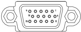
| PIN | Toekenning | PIN | Toekenning | PIN | Toekenning |
| 1 | RED | 6 | Ground | 11 | N.C. |
| 2 | GREEN | 7 | Ground | 12 | N.C. |
| 3 | BLUE | 8 | Ground | 13 | HSYNC |
| 4 | N.C. | 9 | N.C. | 14 | VSYNC |
| 5 | Ground | 10 | Ground | 15 | N.C. |
A.6 Modem/telefonconnector (RJ11)
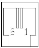
| PIN | Toekenning |
| 1 | TIP |
| 2 | RING |
A.7 LAN-connector (RJ45)
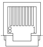
| PIN | Toekenning | PIN | Toekenning |
| 1 | TX+ | 5 | Ground |
| 2 | TX- | 6 | RX- |
| 3 | RX+ | 7 | Ground |
| 4 | Ground | 8 | Ground |
A.8 S-Video-connector
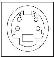
| PIN | Toekenning | PIN | Toekenning |
| 1 | Ground | 3 | Y |
| 2 | Ground | 4 | C |
A.9 IEEE 1394-connector
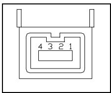
| PIN | Toekenning | PIN | Toekenning |
| 1 | TPB0 | 3 | TPA0 |
| 2 | TPB0# | 4 | TPA0# |
Bijlage B: Hot Keys
Bijlage D: De poortreplicator
CLASS 1 LASER PRODUCT KLASSE 1 LASER PRODUKT

APM (Advanced Power Management) 1.2 et ACPI (Advanced Configuration Power Interface) 1.0.
SYSTEME D'EXPLOitation
Windows 98 SE (ACPI ou APM), Windows NT, Windows 2000 et Windows Millennium.
OPTIONS
| AMIBIOS HIFLEX ENGLISH SETUP - VERSION 1.19 (C)2000 American Megatrends, Inc. All Rights Reserved |
| BIOS Revision 700A_A0x |
| Standard CMOS Setup |
| Advanced CMOS Setup |
| System Security Setup |
| Power Management Setup |
| Boot Device Setup |
| Peripheral Setup |
| Auto Configuration with Defaults |
| Save Settings and Exit |
| Exit Without Saving |
| Standard CMOS setup for changing time, date, hard disk type, etc. ESC: Exit ↑↓: Sel F3/F4:Color F10:Save & Exit |
| AMIBIOS SETUP - ADVANCED CMOS SETUP (C)2000 American Megatrends, Inc. All Rights Reserved | |
| Video out Type NTSC LCD Panel View Expansion On Internal Mouse Enabled Suspend Warning Tone Enabled Intel(R)SpeedStep(TM)Technology Automatic | Select the appropriate Video Standard for your country. ‘NTSC’ is for USA/Japan, and ‘PAL’ is for Europe. ESC: Exit ↑↓: Sel PgUp/PgDn: Modify F3/F4: Color |
| AMIBIOS SETUP - SYSTEM SECURITY SETUP (C)2000 American Megatrends, Inc. All Rights Reserved | |
| Change Supervisor Password Press Enter | If supervisor password is entered, the system requires the supervisor password to enter this Setup utility. Pressing Ctrl-Alt-Backspace locks up the keyboard until the password is entered. The Cap Lock and Scroll Lock LEDs will flash in sequence while waiting for the user to enter a password. |
| Change User Password Press Enter | |
| Boot Password Required No | |
| Resume Password Required No | |
| ESC: Exit ↑↓: Sel PgUp/PgDn: Modify F3/F4: Color | |
| AMIBIOS SETUP - POWER MANAGEMENT SETUP (C)2000 American Megatrends, Inc. All Rights Reserved | |
| Power Switch Power Button | Use 'Power Button' to power the system On or Off. Use 'Sleep Button' to enter or resume from suspend mode. |
| Power Management Under AC Power Off | |
| Power Saving Level Off | |
| Hard Disk Time-out Off | |
| Video Time-out Off | |
| Standby Time-out Off | |
| Auto Suspend Time-out Off | |
| LCD Suspend Disabled | |
| Suspend Option Suspend | |
| Auto Save To File Disabled | |
| Wake Up Alarm Disabled | |
| Resume Alarm Time Off | |
| ESC: Exit ↑↓: Sel PgUp/PgDn: Modify F3/F4: Color | |
Control, Hard Disk Time-out, Video Time-out, Standby Time-out et Auto Suspend Time-out.
| AMIBIOS SETUP - BOOT DEVICE SETUP (C)2000 American Megatrends, Inc. All Rights Reserved | |
| Quick Boot Enabled | “Enabled” allows the system to skip part of test during system is booting. |
| Silent Boot Enabled | |
| Boot Display Device Simul. Mode | |
| BootUp Num-Lock Off | |
| 1stBoot Device CD/DVD | |
| 2ndBoot Device Floppy | |
| 3rdBoot Device 1stIDE-HDD | |
| Try Other Boot Devices Yes | |
| ESC: Exit ↑↓: Sel PgUp/PgDn: Modify F3/F4: Color | |
| AMIBIOS SETUP - PERIPHERAL SETUP (C) 1998 American Megatrends, Inc. All Rights Reserved | |
| Internal Hard Drive Enabled | Available Options: |
| OnBoard Serial Port1 Auto | Enable |
| OnBoard Parallel Port1 ECP | Disabled |
| ESC: Exit ↑↓: Sel | |
| Broche | Affectation | Broche | Affectation | Broche | Affectation |
| 1 | Carrier detect | 4 | Data Terminal | 7 | Req. to send |
| 2 | Received data | 5 | MASSE | 8 | Clear to send |
| 3 | Transmit data | 6 | Data Send | 9 | Ring indicator |
IDE Integrated Drive
SPP Standard Parallel Port
This Class B digital apparatus meets all requirements of the Canadian Interference-Causing Equipment Regulations.
U.S. Regulations Governing the Use of Modems
This equipment complies with Part 68 of the FCC Rules.
On this equipment is a label that contains, among other information, the FCC registration number and Ringer Equivalence Number (REN) for this equipment. You must, upon request, provide this information to your telephone company. If your telephone equipment causes harm to the telephone network, the Telephone Company may discontinue your service temporarily. If possible, they will notify in advance. But, if advance notice is not practical, you will be notified as soon as possible. You will be informed of your right to file a compliant with the FCC.
Your telephone company may make changes in its facilities, equipment, operations, or procedures that could affect proper operation of your equipment. If they do, you will be notified in advance to give you an opportunity to maintain uninterrupted telephone service. The FCC prohibits this equipment to be connected to party lines or co-telephone service. In the event that this equipment should fail to operate properly, disconnect the equipment from the phone line to determine if it is causing the problem. If the problem is with the equipment, discontinue use and contact your dealer or vendor.
The FCC also requires the transmitter of a FAX transmission be properly identified (per FCC Rules Part 68, Sec 68.381 (C) (3)).
U.K. Modem Compliance Information
This modem is approved by the secretary of state at the Department of Trade and Industry for connection to a single exchange line of the public switched telephone network run by certain licensed public telecommunication operators or system connected there to (Direct exchange lines only, not shared service or 1-1 carrier systems).
This modem is also suitable for connection to Private Automatic Branch Exchange (PABX's) which return secondary proceed indication.
If this modem is to be used with a PBX which has extension wiring owned by BT, connection of the modem the PBX can only be carried out by BT; or by the authorized maintainer of the PBX unless the authorized maintainer has been given 14 days written notice that the connection is to be made by another person; and that period of notification has expired.
This modem is suitable for use only on telephone lines proved with Loop Disconnect or Multi-Frequency Dialing Facilities.
Users of this modem are advised that the approval is for connection to the PSTN via the telephone line interface supplied with it. Connection of a modem to the PSTN by any other means will invalidate the approval.
There is no guarantee of correct working in all circumstances. Any difficulties should be referred to your supplier.
Some network operators require that intended users of their network request permission to connect and for the installation of an appropriate socket.
The Ringer Equivalence Number (REN) of this modem is 1. REN is guide to the maximum number of apparatus that can simultaneously be connected to one telephone line. The REN value of each apparatus is added together, and should not exceed 4. Unless otherwise marked, a telephone is assumed to have a REN of 1.
This modem is only approved for use of the following facilities:
Storage of telephone numbers for retrieval by a predator mined code.
- Detection of initial proceed indication.
Automatic calling/ automatic answering.
- Tone detection.
- Loud-speaking facility.
This modem is not approved for connection to U.K./private speech-band services. This modem does not support an automatic re-dial function. Any other usage will invalidate the approval of your modem, if as a result, it then ceases to confirm to the standards against which approval was granted. The approval of this modem is invalidated if the apparatus us subject to modification in any material way not authorized by the BABT or if it is used with, or connected to external software that have not been formally accepted by BABT.
- LCD PANEL VIEW EXPANSION
- SUSPEND WARNING TONE
- CHANGE SUPERVISOR PASSWORD (HAUPTPASSWORD)
- BOOT PASSWORD REQUIRED
- RESUME PASSWORD REQUIRED
- POWER SWITCH
- POWER MANAGEMENT UNDER AC POWER
- AUTO SUSPEND TIME-OUT
- QUICK BOOT
- TRY OTHER BOOT DEVICES
- 11.8 PERIPHERAL SETUP (PERIPHERIE-SETUP)
- INTERNAL HARD DRIVE
- CLASS 1 LASER PRODUCT KLASSE 1 LASER PRODUKT
- TRADEMARKS
- STANDARDS
- CONTENTS
- CHAPTER 1 INTRODUCTION. 1-1
- CHAPTER 2 BEFORE YOU BEGIN. 2-1
- CHAPTER 3 KEYBOARD 3-1
- CHAPTER 4 FDD/HDD DRIVES. 4-1
- CHAPTER 5 THE LCD SCREEN. 5-1
- CHAPTER 6 BATTERY 6-1
- CHAPTER 7 MEMORY 7-1
- CHAPTER 8 THE CD/DVD-ROM DRIVE. 8-1
- CHAPTER 9 PERIPHERALS 9-1
- CHAPTER 10 THE CD-ROM DISC 10-1
- CHAPTER 11 CONFIGURING YOUR SYSTEM. 11-1
- APPENDIX A - CONNECTORS AND PIN ASSIGNMENTS. A-1
- APPENDIX B - HOT-KEYS. B-1
- APPENDIX C - GLOSSARY. C-1
- APPENDIX D - PORT REPLICATOR. D-1
- APPENDIX E - OTHER KEYBOARDS. .E-1
- APPENDIX F - ERROR LOG. .F-1
- APPENDIX G - AGENCY REGULATORY NOTICES............G-1
- CHAPTER 1 INTRODUCTION
- OVERVIEW
- 1.1 STANDARD FEATURES
- SYSTEM
- DISPLAY
- STORAGE DEVICE
- KEYBOARD
- CONNECTIVITY AND EXPANSION
- POWER
- PHYSICAL
- ENVIRONMENT
- WARNING
- POWER MANAGEMENT
- OPERATING SYSTEM
- OPTIONS
- 1.2 SPECIAL FEATURES
- MEMORY EXPANSION
- HOT KEYS
- TOUCHPAD
- PCMCIA
- SOUND SYSTEM
- CHAPTER 2 BEFORE YOU BEGIN
- 2.1 CHECKING WHAT YOU RECEIVED
- 2.2 EXAMINING YOUR COMPUTER
- VIEW OF THE FRONT PANEL
- THE DISCPLAY FUNCTION
- 2.3 THE TWO POWER LEDS
- THE BATTERY PACK LED
- THE POWER ON LED
- NOTE
- 2.4 THE SEVEN SYSTEM LEDS
- THE AC ADAPTER LED
- THE CD-ROM/DVD-ROM LED
- THE HDD LED
- THE FDD LED
- THE NUM LOCK LED
- THE CAPS LOCK LED
- THE SCROLL LOCK LED
- CHAPTER 3 KEYBOARD
- 3.1 GENERAL VIEW
- EXAMPLE
- CAPSLOCK KEY
- PRINT SCREEN KEY
- 3.2 THE EMBEDDED NUMERIC KEYPAD
- 3.3 OTHER KEYS
- THE FN KEY
- THE ALT (ALTERNATE) KEY
- THE WINDOWS (KEY
- THE WINDOWS ( ) KEY
- CHAPTER 4 FDD/HDD DRIVES
- 4.1 THE FLOPPY DISKETTE DRIVE (FDD)
- 4.2 REMOVAL HARD DISK DRIVE (HDD)
- 4.3 REMOVING THE HARD DISK DRIVE
- CHAPTER 5 THE LCD SCREEN
- 5.1 ADJUSTING CONTRAST-BRIGHTNESS
- CONTRAST CONTROL
- BRIGHTNESS CONTROL
- 5.2 LCD/CRT/TV DISPLAY
- NOTE: WHEN YOU SWITCH YOUR DISPLAY FROM CRT ONLY TO LCD/CRT (SIMUL), THE FOLLOWING SYMPTOMS MAY OCCUR
- 5.3 RESOLUTIONS AND COLORS
- TFT
- CRT
- CHAPTER 6 BATTERY
- 6.1 BATTERY PACK
- 6.2 RECHARGING THE BATTERY PACK
- 6.3 QUESTIONS AND ANSWERS
- 6.4 BATTERY BUTTON, LEDS AND ALARM
- BATTERY LOW 1
- BATTERY LOW 2
- 6.5 BATTERY MAINTENANCE
- 6.6 POWER CONSUMPTION
- LCD COVER SWITCH
- HARD DISK TIME OUT
- SUSPEND-TO-RAM
- SAVE-TO-FILE (HIBERNATION MODE)
- 6.7 REDUCING POWER CONSUMPTION
- 6.8 REMOVING/INSERTING THE BATTERY PACK
- CHAPTER 7 MEMORY
- 7.1 INSERTING/REMOVING MEMORY MODULE
- CHAPTER 8 THE CD/DVD-ROM DRIVE
- 8.1 THE CD/DVD-ROM DRIVE PANEL
- CD/DVD-ROM DRIVE PANEL
- EJECT BUTTON
- EMERGENCY HOLE
- 8.2 DISC LOADING/EJECTION
- DISC LOADING
- DISC EJECTION
- 8.3 ROM DISC MAINTENANCE
- DISC HANDLING
- DISC CLEANING
- CHAPTER 9 PERIPHERALS
- 9.1 PS/2 KEYBOARD CONNECTOR
- 9.2 PARALLEL PORT
- 9.3 COM PORT
- 9.4 USB CONNECTOR
- 9.5 VGA CONNECTOR
- 9.6 S-VIDEO CONNECTOR
- 9.7 AUDIO JACKS
- 9.8 PCMCIA PORT
- 9.9 IRDA PORT
- 9.10 FAX PORT
- 9.11 ETHERNET LAN PORT
- 9.12 IEEE 1394 PORT
- CHAPTER 10 THE CD-ROM DISC
- 10.1 DOS UTILITIES AND DRIVERS
- THE "SAVE-TO-FILE" FILE
- 10.2 WINDOWS 98 DRIVERS AND APPLICATIONS
- 10.3 WINDOWS NT 4.0 DRIVERS AND APPLICATIONS
- 10.4 WINDOWS 2000 DRIVERS AND APPLICATIONS
- CHAPTER 11 CONFIGURING YOUR SYSTEM
- 11.1 CONFIGURATION SOFTWARE
- 11.2 RUNNING THE SETUP UTILITY
- MOVEMENT WITHIN THE SETUP UTILITY
- 11.3 STANDARD CMOS SETUP
- DATE AND TIME
- FLOPPY DRIVE A
- PRI MASTER, AND 32BIT MODE
- SEC MASTER AND 32 BIT MODE
- BOOT SECTOR VIRUS PROTECT
- 11.4 ADVANCED CMOS SETUP
- VIDEO OUT TYPE
- INTERNAL MOUSE
- INTEL (R) SPEEDSTEP (TM) TECHNOLOGY
- 11.5 SYSTEM SECURITY SETUP
- CHANGE SUPERVISOR PASSWORD
- CHANGE USER PASSWORD
- 11.6 POWER MANAGEMENT SETUP
- POWER SAVING LEVEL
- HARD DISK TIME-OUT
- VIDEO TIME-OUT
- STANDBY TIME-OUT
- LCD SUSPEND
- SUSPEND OPTION
- AUTO SAVE TO FILE
- WAKE UP ALARM/RESUME ALARM TIME
- 11.7 BOOT DEVICE SETUP
- SILENT BOOT
- BOOT DISPLAY DEVICE
- BOOTUP NUM-LOCK
- 1ST BOOT DEVICE
- 2ND BOOT DEVICE
- 3RD BOOT DEVICE
- 11.8 PERIPHERAL SETUP
- ONBOARD SERIAL PORT1
- ONBOARD PARALLEL PORT1
- 11.9 AUTO CONFIGURATION WITH DEFAULTS
- 11.10 SAVE SETTINGS AND EXIT
- 11.11 EXIT WITHOUT SAVING
- APPENDIX A - CONNECTORS AND PIN ASSIGNMENTS
- A.1 KEYBOARD OR PS/2 MOUSE CONNECTOR
- A.2 PRINTER PORT CONNECTOR
- A.3 COMMUNICATION PORT CONNECTOR
- A.4 USB PORT CONNECTOR
- A.5 VGA MONITOR CONNECTOR
- A.6 MODEM/PHONE CONNECTOR (RJ11)
- A.7 LAN CONNECTOR (RJ45)
- A.8 S-VIDEO CONNECTOR
- A.9 IEEE 1394 CONNECTOR
- APPENDIX B - HOT-KEYS
- INTERNET MAIL HOT KEY
- MAIL HOT KEY
- AUDIO CD HOT KEY
- SUSPEND-TO-RAM HOT KEY
- LCD/CRT HOT KEY
- CONTRAST DECREASE HOT KEY
- CONTRAST INCREASE HOT KEY
- BRIGHTNESS DECREASE HOT KEY
- BRIGHTNESS INCREASE HOT KEY
- VOLUME DECREASE HOT KEY
- VOLUME INCREASE HOT KEY
- APPENDIX C - GLOSSARY
- APPENDIX D - PORT REPLICATOR
- APPENDIX E - OTHER KEYBOARDS
- APPENDIX F - ERROR LOG
- PERIPHERALS ATTACHED
- PCMCIA CARD
- SOFTWARE WHERE PROBLEM OCCURS
- PROBLEM DESCRIPTION
- APPENDIX G - AGENCY REGULATORY NOTICES
- G.1 SAFETY INSTRUCTIONS
- WARNING: THE CD-ROM/DVD-ROM IN THIS NOTEBOOK EMPLOYS A LASER SYSTEM
- G.2 AGENCY NOTICE
- DECLARATION OF CONFORMITY - UNITED STATES ONLY
- FEDERAL COMMUNICATIONS COMMISSION NOTICE
- MODIFICATIONS
- CABLES
- CANADIAN NOTICE
- AVIS CANADIEN
- U.S. REGULATIONS GOVERNING THE USE OF MODEMS
- U.K. MODEM COMPLIANCE INFORMATION
- TER KENNISGEVING
- A.5 VGA MONITOR-CONNECTOR
- A.6 MODEM/TELEFONCONNECTOR (RJ11)
- A.7 LAN-CONNECTOR (RJ45)
- A.8 S-VIDEO-CONNECTOR
- A.9 IEEE 1394-CONNECTOR
- BIJLAGE B: HOT KEYS
- BIJLAGE D: DE POORTREPLICATOR
- SYSTEME D'EXPLOITATION
- IDE INTEGRATED DRIVE
- SPP STANDARD PARALLEL PORT
Brand : MAXDATA
Model : 700T
Category : Laptop