
CA12 - Audio Amplifier YORKVILLE - Free user manual and instructions
Find the device manual for free CA12 YORKVILLE in PDF.


| Product type | Multi-zone professional installation audio amplifier |
| Brand | YORKVILLE |
| Model | CA12 |
| Power (4 ohms or 70 V) | 50 W per channel (stereo) / 100 W bridged (8 ohms) |
| Power (8 ohms) | 25 W per channel |
| Minimum impedance | 4 ohms (stereo) / 8 ohms (bridged) |
| Frequency response | 40 Hz - 20 kHz (+/- 3 dB) |
| Noise and hum | -97 dB |
| Number of channels | 12 (6 stereo zones or 6 mono zones bridged) |
| Inputs | RCA and screw terminal (Bus), RCA and screw terminal (line) |
| Outputs | Speaker terminals (rear), Bus outputs (RCA) |
| Controls | Gain, Line/Bus selector, Limiter In/Out, Stereo/Bridged, +4 ohms/70V |
| Indicators | LED On/Clip (green/red), LED Power |
| Power supply | 115 V/60 Hz or 230 V/50 Hz (switchable via selector) |
| Power consumption | Not specified |
| Dimensions (W x D x H) | 43.5 x 43 x 8.5 cm |
| Weight | 20.5 kg |
| Warranty | 2 years (10 years for cabinet), transferable, valid in Canada and the United States |
| Maintenance and cleaning | Unplug before cleaning; use a dry soft cloth; do not expose to water or solvents |
| Safety | Do not open, do not expose to water, observe polarity, ensure adequate ventilation, use a stable support |
Frequently Asked Questions - CA12 YORKVILLE
User questions about CA12 YORKVILLE
0 question about this device. Answer the ones you know or ask your own.
Ask a new question about this device
Download the instructions for your Audio Amplifier in PDF format for free! Find your manual CA12 - YORKVILLE and take your electronic device back in hand. On this page are published all the documents necessary for the use of your device. CA12 by YORKVILLE.
USER MANUAL CA12 YORKVILLE
IMPORTANT SAFETY INSTRUCTIONS
INSTRUCTIONS PERTAINING TO A RISK OF FIRE, ELECTRIC SHOCK, OR INJURY TO PERSONS
CAUTION:
TO REDUCE THE RISK OF ELECTRIC SHOCK, DO NOT REMOVE COVER (OR BACK).
NO USER SERVICEABLE PARTS INSIDE.
REFER SERVICING TO QUALIFIED SERVICE PERSONNEL.
Read Instructions
The Owner's Manuals should be read and understood before operation of your unit. Please, save these instructions for future reference.
Packaging
Keep the box and packaging materials, in case the unit needs to be returned for service.
Warning
When using electric products, basic precautions should always be followed, including the following:
Power Sources
Your unit should be connected to a power source only of the voltage specified in the owners manual or as marked on the unit. This unit has a polarized plug. Do not use with an extension cord or receptacle unless the plug can be fully inserted. Precautions should be taken so that the grounding scheme on the unit is not defeated.
Hazards
Do not place this product on an unstable cart, stand, tripod, bracket or table. The product may fall, causing serious personal injury and serious damage to the product. Use only with cart, stand, tripod, bracket, or table recommended by the manufacturer or sold with the product. Follow the manufacturer's instructions when installing the product and use mounting accessories recommended by the manufacturer.
The apparatus should not be exposed to dripping or splashing water; no objects filled with liquids should be placed on the apparatus.
Terminals marked with the "lightning bolt" are hazardous live; the external wiring connected to these terminals require installation by an instructed person or the use of ready made leads or cords.
Ensure that proper ventilation is provided around the appliance.
No naked flame sources, such as lighted candles, should be placed on the apparatus.
Power Cord
The AC supply cord should be routed so that it is unlikely that it will be damaged. If the AC supply cord is damaged DO NOT OPERATE THE UNIT.
Service
The unit should be serviced only by qualified service personnel.
INSTRUCTIONS RELATIVES AU RISQUE DE FEU, CHOC ÉLECTRIQUE, OU BLESSURES AUX PERSONNES
AVIS:
AFIN DE REDUIRE LES RISQUE DE CHOC ELECTRIQUE, N'ENLEVEZ PAS LE COUVERT (OU LE PANNEAU ARRRIERE)
NE CONTIENT AUCUNE PIECE REPARABLE PAR L'UTILISATEUR.
CONSULTEZ UN TECHNICIEN QUALIFIE POUR L'ENTRETIENT
CA12 Multi-Zone Professional PA Amplifier
Introduction
The CA12 is a major step forward in installation amplifier technology. Twelve mono Zone power amplifiers, featuring 85% class D design technology, can operate as 6 independent Zone amplifiers. Self-explanatory Input and Output connections are easy to follow since any of the 12 mono amplifiers can be connected to either 70-Volt, 8-Ohm or 4-ohm speaker circuits.
Each of the 12 mono amplifiers has their own input and output connectors and level controls. Up to 6 stereo Zones (4-ohm or 70-Volt at 50 Watts / channel), 6 mono/bridged Zone amplifiers (110 Watt bridged 8-ohm or 140-Volt). Each Zone can be configured independently allowing a combination of Stereo 4-ohm or 70 Volt and Mono/Bridged 8-ohm or 140 Volt Zones. Dual-function LEDs on the front panel provide both activity and Clip indication for each pair of amplifiers, which also have their own button-selectable Limiter; Stereo/Bridge modes and 4-ohm/70V modes are also selectable.
The Ch. Input Line/Bus switch selects between either the Bus Input (button depressed) or the individual Zone's Input signal. Additional features include: any amplifier with no signal at its input is automatically shut off and the CA12 is able to operate either on 120V/60Hz or 220V/50Hz AC mains.
Features and Functions
AC Mains. The CA12 comes configured to connect to 115V/60Hz mains. For use with 230V/50Hz mains set the rear panel Voltage Select switch to 230V (also, replace the T10.0AL/250V fuse with a T5.0AL/250V fuse).
Front Panel
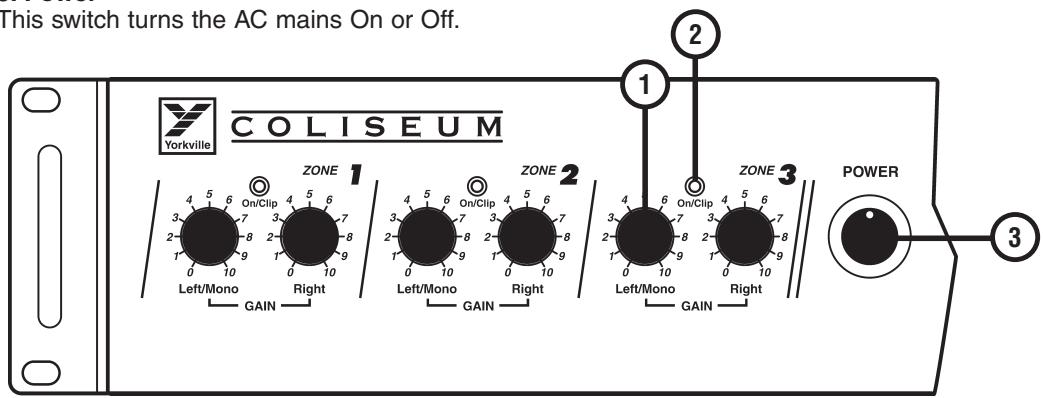
1. Left/Mono and Right Controls
These controls regulate the level for each amplifier. For the Zones set up in Mono/Bridge mode only the Left/Mono Control will affect the level.
2. On/Clip LED
The individual channel's On/Clip LED will flash to indicate activity, flashing red will indicate clipping. Reduce levels if clipping is indicated (the LED does not indicate which Zone channel is clipping).
3. Power
This switch turns the AC mains On or Off.

Rear Panel
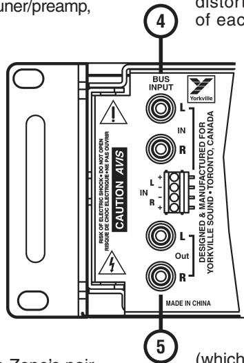
4. Bus Inputs
RCA connectors and a screw terminal strip are provided to connect your mixer, stereo tuner/preamp, CD player or other audio media device.
Note: use only one type of source.
5. Bus Outputs
These RCA connectors are simply in parallel with the Bus Inputs and enable you to interconnect the CA12 with another CA12 or amplifier.
Note: only the Input Bus signals will be patched to Output.
The Following Applies to Each One of the Zone Input Sections
6. Ch Line Input
These inputs allow connection of sources directly to the individual channels. This input allows stereo, line-level source or two separate mono audio sources. If you Bridge the Zone's pair of amplifiers into an 8-ohm speaker circuit, use the Left input and connect a mono source.
7. Line/Bus Button
Each Zone's input source can be selected using this switch. Depress the button to select the audio program coming from the Bus Input or leave it in the up position to use the Zone's Line Input.
8. Remote Volume Jack
Using a cable terminated with a 1 / 4 -inch mono phone plug, connect your DC remote volume control source (a potentiometer for example) here. When connected, this feature bypasses both front panel controls for this Zone.
Note: Use a 50,000 ohm B taper potentiometer. Connect the wiper
of the potentiometer to the tip of the stereo phone plug. Connect the ring of the stereo phone plug to the top of the potentiometer resistive element, and connect the bottom of the potentiometer resistive element to the sleeve of the stereo phone plug. The tip, ring, and sleeve electrical circuits must remain isolated from any other ground or electrical connection.
9. Limiter In/Out Button
The Limiter In/Out button activates a pre-set input limiter, which helps reduce the level of accidental loud noises and clipping distortion for each Zone (both channels of each Zone).
10. Stereo/Bridge Button
For stereo, or dual-zone mono operation, at 50 Watts per channel leave this in the up position. To combine (i.e. Bridge) the two into a 110-Watt mono amplifier, depress the button. In Bridge mode, the +4 ohm / +70V button must be in the +4 ohm position (depressed) to allow for the 8-ohm speaker circuit, not 4-ohms! In bridge mode, an amplifier encounters a load that is about one half of its actual value - a 4-ohm load would therefore be 2-ohms to a bridged amp and if the amplifier isn't designed to run safely into such a low impedance
(which the CA12 is not) damage may occur to the amplifier. We do not recommend connecting a 70V speaker circuit while in Bridge mode as the output will be at 140V and the sound can be distorted.
11. +4 ohm / 70V Button
Leave this switch in the up position if you are connecting 4-ohm or 8-ohm speaker circuit (Stereo mode). Depress the button to connect a 70V speaker circuit.
12. Speaker Connections
Insert bare wire ends here and tighten the retaining screws to secure properly. For a stereo Zone or dual mono Zones, connect the + and - system leads from each Zone to one +4 ohm and its adjacent - Neg terminal in the L & R terminal groupings. In Bridge mode, connect the + and - leads from an 8-ohm speaker circuit (not 4-ohms - see Stereo/
Bridge Button section above) to each of the +4 ohm terminals.


Power @ min. impedance (Watts) 50W / ch. (4 ohm or 70 V; 25 W / ch. (8 ohm)
100W (8 ohms BRIDGED)
Minimum Impedance (ohms)
4 ohms (8 ohms bridged)
Frequency Response (Hz +/-3dB) 40 Hz - 20 kHz
Hum and Noise (dB) -97 dB
Input Channels 12 (6 Stereo Zones)
Channel - inputs RCA / Terminal strip on Main Bus input
Channel - controls Gain
Input Sensitivity (mV) 650 mV
Line Out (type / configuration) Bus Output RCA
LED Indicators Power,Clip
External speaker output / location Terminal Strip (rear)
Dimensions (DWH, inches) 16.75 × 16.75 × 3.25
Dimensions (DWH, cm) 43.5 × 43 × 8.5
Weight (Ibs / kg) 45 / 20.5
Specifications
Yorkville's two and ten-year unlimited warranty on this product is transferable and does not require registration with Yorkville Sound or your dealer. If this product should fail for any reason within two years of the original purchase date (ten years for the wooden enclosure), simply return it to your Yorkville dealer with original proof of purchase and it will be repaired free of charge. This includes all Yorkville products, except for the YSM Series studio monitors, Coliseum Mini Series and TX Series Loudspeakers.
Freight charges, consequential damages, weather damage, damage as a result of improper installation, damages due to exposure to extreme humidity, accident or natural disaster are excluded under the terms of this warranty. Warranty does not cover consumables such as vacuum tubes or par bulbs. See your Yorkville dealer for more details. Warranty valid only in Canada and the United States.
Garantie Illimitée
Voice: (716) 297-2920
Fax: (716) 297-3689

Yorkville Sound 550 Granite Court Pickering, Ontario
Yorkville Sound Inc. 4625 Witmer Industrial Estate
Niagara Falls, New York 14305 USA

WEB: www.yorkville.com
Niagara Falls, New York
14305 USA
Voice: (716) 297-2920
Fax: (716) 297-3689

Quality and Innovation Since 1963
Printed in China
Manual-Owners-CA12-00-1v2 • Nov 30/2009
- IMPORTANT SAFETY INSTRUCTIONS
- INSTRUCTIONS PERTAINING TO A RISK OF FIRE, ELECTRIC SHOCK, OR INJURY TO PERSONS
- CAUTION:
- Read Instructions
- Packaging
- Warning
- Power Sources
- Hazards
- Power Cord
- Service
- INSTRUCTIONS RELATIVES AU RISQUE DE FEU, CHOC ÉLECTRIQUE, OU BLESSURES AUX PERSONNES
- AVIS:
- CA12 Multi-Zone Professional PA Amplifier
- Introduction
- Features and Functions
- Front Panel
- Left/Mono and Right Controls
- On/Clip LED
- Power
- Rear Panel
- Bus Inputs
- Bus Outputs
- The Following Applies to Each One of the Zone Input Sections
- Ch Line Input
- Line/Bus Button
- Remote Volume Jack
- Limiter In/Out Button
- Stereo/Bridge Button
- +4 ohm / 70V Button
- Speaker Connections
- Specifications
- Garantie Illimitée
Brand : YORKVILLE
Model : CA12
Category : Audio Amplifier