
CA1T - Audio Amplifier YORKVILLE - Free user manual and instructions
Find the device manual for free CA1T YORKVILLE in PDF.


| Product type | Mono tabletop audio amplifier |
| Model | CA1T |
| Brand | YORKVILLE |
| Rated power | 120 W (max. 180 W) |
| Power with 24 VDC supply | 90 W |
| Frequency response | 50 - 15,000 Hz (±3 dB) |
| Total harmonic distortion | ≤ 1% (1 kHz, rated power) |
| Signal-to-noise ratio | Inputs 1-4, AUX 1-2: >45 dB; Main input: >55 dB |
| Inputs | 1 microphone input (6.3 mm); 3 combo XLR/6.3 mm inputs (mic/line); 2 stereo RCA inputs (AUX); 1 telephone input (600 Ω); 1 main input (RCA) |
| Outputs | Speakers: 4 Ω, 25/70/100 V; 1 PRE OUT (RCA); 1 MONITOR output (6.3 mm); 1 auxiliary speaker output 1 W/8 Ω |
| Tone controls | Bass ±10 dB (100 Hz); Treble ±10 dB (10 kHz) |
| Special features | Voice priority on input 1; telephone priority; zone paging (Z1-Z4 and ALL); contact closure activation; LED VU meter; AM/FM DTS tuner (CA1T only) |
| Mains power supply | 115/230 VAC, 50/60 Hz, 400 VA |
| External power supply | 24 VDC (5 A max., external battery); automatic switchover |
| Dimensions (W x H x D) | 480 x 150 x 320 mm |
| Weight | 12 kg |
| Safety | Short-circuit protection; mains fuse; grounding; do not open the device; do not expose to moisture |
| Maintenance | Clean with a dry cloth; do not use solvents or volatile substances |
| Repairability | Repairs must be carried out by an authorized Yorkville service center |
Frequently Asked Questions - CA1T YORKVILLE
User questions about CA1T YORKVILLE
0 question about this device. Answer the ones you know or ask your own.
Ask a new question about this device
Download the instructions for your Audio Amplifier in PDF format for free! Find your manual CA1T - YORKVILLE and take your electronic device back in hand. On this page are published all the documents necessary for the use of your device. CA1T by YORKVILLE.
USER MANUAL CA1T YORKVILLE
OWNER'S MANUAL PROFESSIONAL PUBLIC ADDRESS AMPLIFIER
CA1·CA1T
IMPORTANT NOTES
- Before connecting and using this amplifier, carefully read the instructions contained in this manual. Please save for future reference.
- This manual is important to the operation of this product and must accompany it when changing owners. This will allow the new owner to get familiar with the product for installation, operation and safety.
- Faulty installation of this apparatus frees Yorkville Sound of all responsibility.
CAUTION
To prevent the risk of fire or electric shock, do not expose this equipment to rain or dampness.
SAFETY PRECAUTIONS
- Please read the notes proceeded by the symbol A with special attention, they provide important safety information.
- The power supply voltage of the amplifier has a sufficiently high value to involve the risk of electrical shock; therefore, never install, connect, or disconnect the equipment with the power supply turned on.
- The metal parts of this equipment are earthed by means of the power cable. If the power socket used to supply power does not have an earth connection, call a qualified electrician who will earth the equipment by means of the terminal.
- Make sure that the power supply cable of the equipment cannot be trodden on, or crushed by objects to ensure that the cable is not damaged.
- To prevent the risk of electric shock, never open the equipment: there are no parts inside that the user can use.
- Make sure that no objects or liquids can get into the speaker, as this could cause a short circuit.
-
Never attempt to make any repairs that are not described in this manual. Contact your authorized service center or qualified personnel when:
-
The equipment does not function (or functions in an anomalous way).
-
The power supply cable has been seriously damaged.
-
Objects or liquids have got into the equipment.
-
The equipment has been subject to heavy impact.
-
If the equipment is not to be used for long periods of time, switch it off and disconnect the power supply cable.
- If the equipment gives off any strange odors or smoke switch it off immediately and disconnect the power from the supply cable.
PRECAUTIONS
- Do not obstruct the ventilation grilles of the equipment.
- Avoid having the amplifier work on overload for a long period of time.
- Fully tighten the screw terminals in order to ensure safe contact.
- Do not force buttons, controls etc., when trying to use them.
- When cleaning external parts, do not use thinners, spirits, or any other volatile substances.
NOTES IMPORTANT
The amplifiers in the CA1, CA1T series have been expressly designed for transmitting announcements through all PA sound systems. They incorporate the following functions:
- One unbalanced 6.3 mm microphone input jack, microphone sensitivity.
- Three combo jacks (XLR and 6.3mm ) inputs, line/microphone switchable sensitivity with selectable 24VDC phantom power supply
- 2 stereo RCA inputs, four stage with selectable sensitivity
- 600Ω telephone paging input
1 PRE OUT output - 1 MONITOR OUTPUT and 1W / 8Ω slave output for monitoring musical signals
- 1 MAIN IN input
- Input 1 priority on the other inputs with vocal activation
- Input 1, 2, 3, 4 priority on the other inputs, activation with contact
- Outputs for speakers with constant impedance (4-ohm) and constant voltage (25-70-100V)
- Treble and bass controls
- VU-meter with LED's
- Protection against short-circuiting between output terminals
- Direct current supplies 24 Vdc
- Optional zone paging functions, four zone paging and all zone paging
- Optional DTS AM/FM tuner (Only CA1T)
Controls and Functions
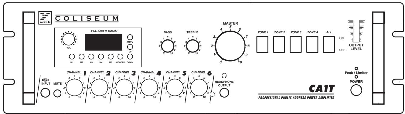
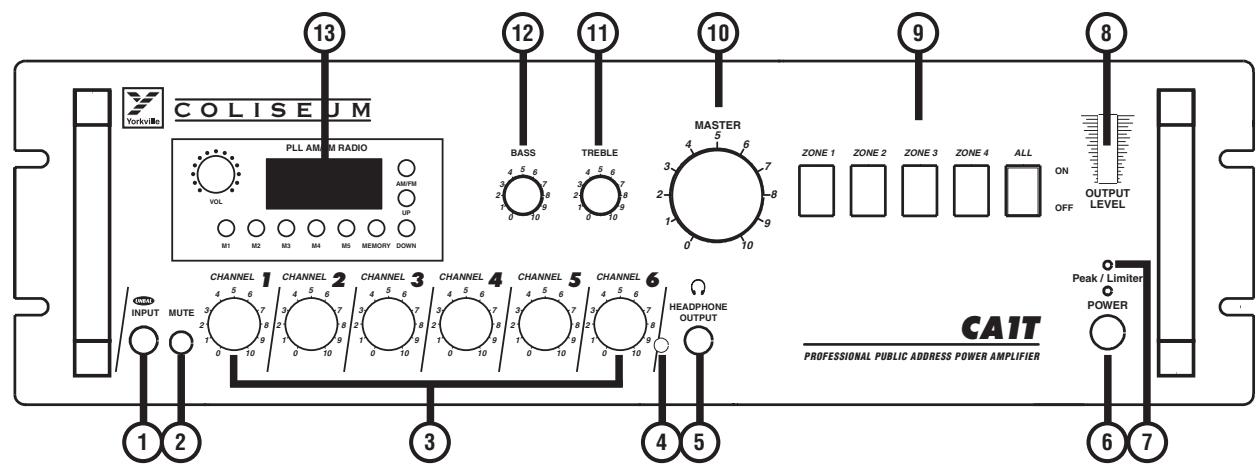
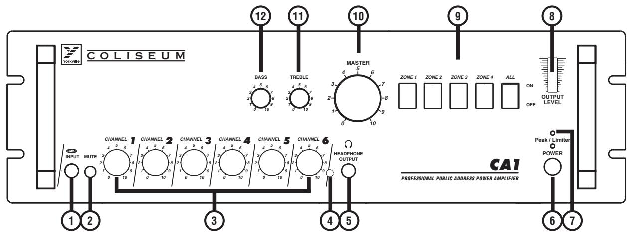
1. CHANNEL 1 Input
This unbalanced input lets you connect a low-impedance dynamic microphone (30-600 ohms). The connector uses 6.3 mm phone jack. The input features VOICE PRIORITY, which overrides all other input signals once a microphone message is sensed. If you want to have this function disabled permanently, please contact a Yorkville Sound Service Center.

Unbalanced Microphone
1/4-inch Mono Phone Plug
2. MUTE Switch
This switch lets you turn VOICE PRIORITY on or off for INPUT 1 (1).
3. Input Level Controls
These controls let you individually set the volume of the sound source that is connected to INPUT 1, INPUT 2, INPUT 3, INPUT 4, AUX 1 and AUX2 / TAPE. Turning the control clockwise increases the volume of the corresponding source. We recommend to leave the controls of the inputs not used to their minimal setting of "0."
4. Music Signal Monitor Output Level Control
This control lets you set the volume of the sound output that is connected to the MONITOR OUTPUT (5) and 1W/8Ω (31). Turning the controls clockwise increases the volume of the corresponding source.
5. MONITOR Output
This allows the signal output of the AUX1, AUX2 / TAPE, CASSETTE and TUNER to be monitored. It can be used to control an audio appliance with input with impedance over 600ohms (e.g. earphone or an additional amplifier etc.). The output signal is controlled only by the volume controls of the AUX1, AUX2 / TAPE, TUNER and music signal level control

(4). This function also behaves as a toggle switch for the 1W / 8Ω (31) additional loudspeaker.
6. POWER Switch
Using the POWER switch lets you turn the main power on or off.
7. Indicator
When switching the amplifier's power on, the Peak/Limiter indicator lights momentarily. When the amplifier's output overloads, the OVERLOAD indicator lights and interrupts the output. For best equipment life, adjust the volume to a lower setting.
8. LED VU-Meter
This LED indicator displays the signal's output level. For proper operation of the amplifier, a correct volume setting is of major importance. The first eight LED segments on the lower portion represent the area between -20dB and 0dB, in which the outputted level should be kept. If the last two segments on the upper portion are lit for a long period of time, this means that the output signal is being driven into clipping (which usually results in audible distortion). You need to adjust the volume to a lower setting.
9. Zone Selection Switches
Speaker lines of each zone (Z1 ~ Z4) can be connected or disconnected independently. To connect the speaker lines, turn the switch on. To disconnect the speaker lines, turn the switch off.
Individual zones can be selected by turning these switches on or off. All speakers connected to a specific zone may be turned on or off in this manner. The ALL switch overrides the individual switches and switches all zones on, regardless of whether or not the individual zone switch is on or off.
10. MASTER Volume Control
The setting of this control determines the output level that is present at the loudspeaker OUTPUT. We recommend to generally adjust the MASTER and the input level controls at moderate settings. Extreme settings, when the MASTER is set to maximum output, and the input controls are nearly set to their minimum or vice versa are not recommended.
11. Common TREBLE Control
When turned clockwise this control enhances the high frequency reproduction, while turning it counter-clockwise attenuates the treble frequencies. If the control is set to its center position, the overall frequency response is not being altered.
12. Common BASS Control
When turned clockwise this control enhances the low frequency reproduction, while turning it counter-clockwise attenuates the bass frequencies. If the control is set to its center position, the overall frequency response is not being altered.
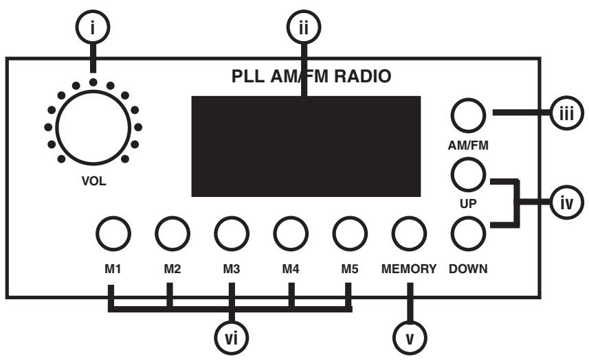
13. Optional DTS AM/FM Tuner (Only CAIT)
i. Radio ON/OFF and volume control (VOL) The radio can be operated if this knob is rotated clockwise and an indication appears on the display (ii). Rotate the volume control clockwise to increase the radio's output signal level.
ii. Display This display indicates the tuned frequency and memory number. When the display is off, the radio does not work.
iii. AM/FM Radio Selection Button (AM/FM) Use this button to select the desired band. The band alternates between AM and FM with each depression of this button.
iv. Tuning Button (UP/DOWN) Use this button to select the desired station. If the down button is pressed for longer than 1.5 seconds, the AM frequency automatically decreases at 10kHz intervals, while the FM frequency automatically decreases at 0.1MHz intervals, till the radio is tuned in. To stop the selection manually, press the down key again during automatic tuning. Similarly, press the UP button will increase the AM frequency at 10kHz intervals and FM frequency at 0.1MHz intervals. The selection stops when radio is tuned in or the UP key is pressed again.
v. MEMORY Button If the button is pressed, then press selection button (M1-M5), the frequency shown on the display is stored together with the memory number. Stored data is kept for about one week even when the power is not supplied.
vi. Selection Button (MI-M5) Up to five of each of AM and FM stations can be stored. Press this button for shows the stored station frequency and memory number on the display (ii).

Rear Panel
Controls and Functions
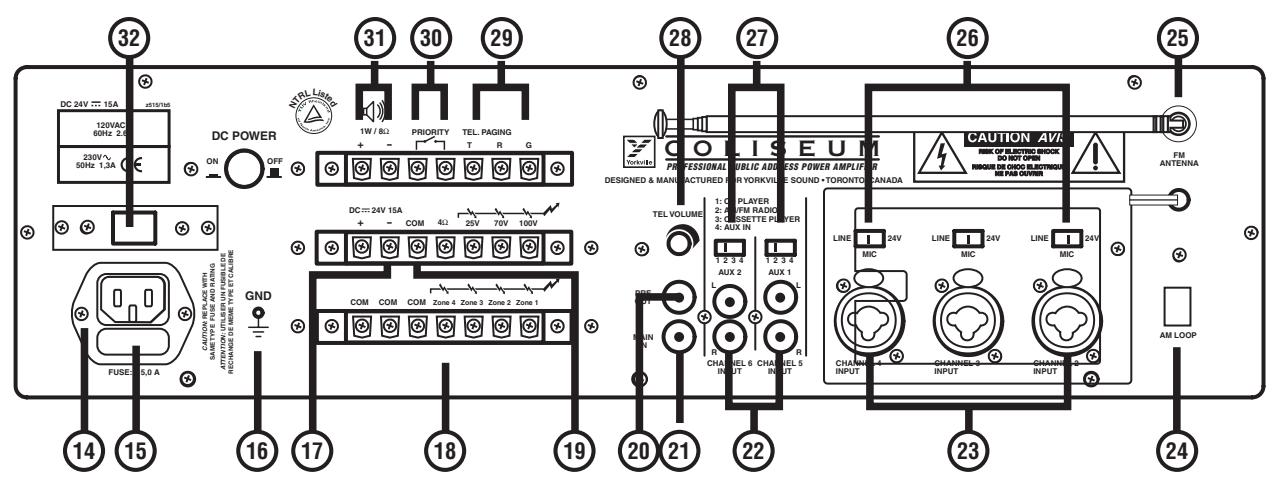
14. Main Cord Connector
This connector is meant to connect the supplied mains (power) cord.
15. AC Fuse
The fuse protecting the AC (alternating current) circuits of the equipment. The fuse should only be changed in the event of a fault, or changing the supply voltage which should be done by at a Yorkville Sound service center.
16. GND Screw
In case the mains outlet being used does not have a ground conductor, this screw offers the possibility to ground the amplifiers metal parts. Leave this procedure to an experienced, qualified electrician to ensure safety.
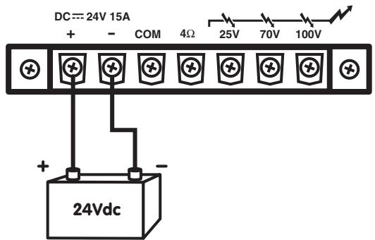
17. Terminals for the DC Battery Supply
These two terminals allow the connection of an external 24 Vdc power supply (e.g. a 24Vdc battery). In this way continuous operation of the amplifier is maintained even during a power outage, since it is automatically switched to the DC power source.
Note: The amplifier is not capable of recharging the connected battery. Thus, it is recommended to have a suitable device at hand. When the amplifier is operated on the DC power source, the nominal power handling capacity drops by approximately 20% .
18. Zone Output Terminal Strip
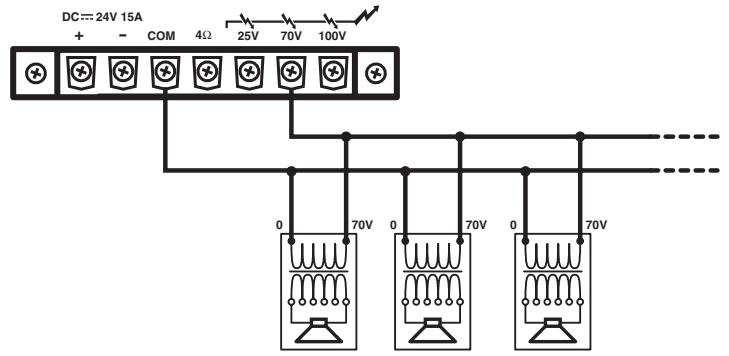
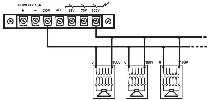
This output terminal connects to the speaker lines. Total speaker wattage is up to nominal power for zones 1-4. When using a zone selector low-impedance speakers cannot be used, default is constant voltage 70V output.
19. Output Terminal Strip
These 5 terminals allow connecting speakers.
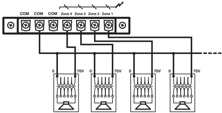
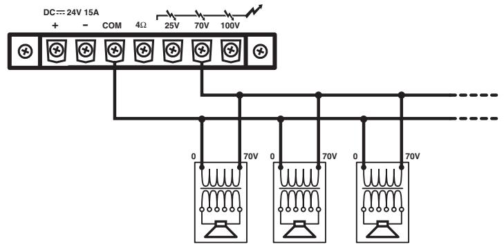
Connecting the speakers to 70V output
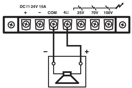
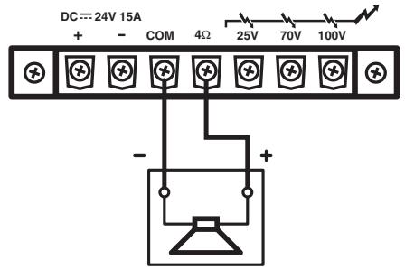
4-ohms
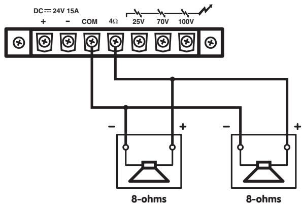
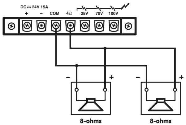
Connecting the speakers to 4-ohm output
Total Impedance 4-ohms
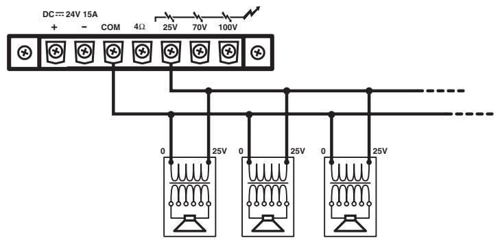
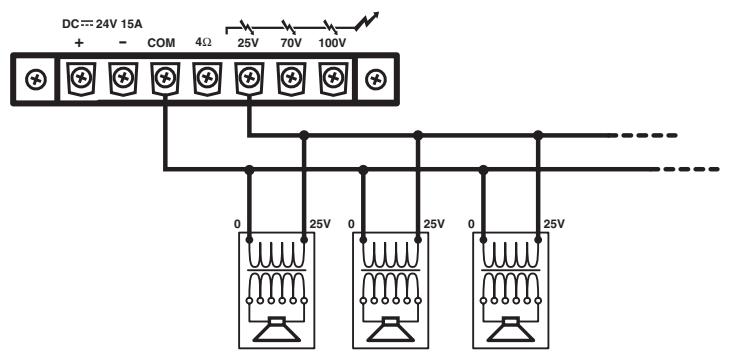
Connecting the speakers to 25V output
Connecting the speakers to 70V output
Connecting the speakers to 100V output
20. PRE OUT Terminal Strip
This terminal strip outputs the mixed audio signals of all sources (that are connected to the amplifier's inputs) and can be used to feed an external power amplifier, a signal processor (e.g. an equalizer) or any other external appliance. The unbalanced signal is affected by the individual input controls. Before using the PRE OUT you need to remove the bridging-strip between this binding post and the MAIN IN terminal (21).
21. MAIN IN Terminal Strip
After removing the bridging-strip between the PRE OUT and the MAIN IN terminals you can use an external signal processor (e.g. an equalizer) in the audio-chain between the pre-amplifier and the power output stage of the power amplifier. This opportunity provides a proper solution whenever shaping or improving the audio signal is necessary (adjusting delay times, equalizing, eliminating the Larsen-effect, etc.). The input is unbalanced, and is affected by the tone controls and the master volume control.
22. AUX 1 and AUX 2 Inputs
These two RCA-type connectors let you connect the two channels of an external high-level unbalanced signal source, such as an AM/FM tuner, a cassette deck, a CD player etc. Use input sensitivity switch (27), suitable for difference appliances.

23. INPUT 2, INPUT 3 and INPUT 4 Inputs
These three balanced/unbalanced combination type jack (XLR and 6.3mm) inputs are meant for the connection of condenser type microphones that use 24V phantom power, dynamic microphones (30-600 ohms) or a high level sound source (e.g. AM/ FM tuner, cassette desk, CD player, etc.). In case you are using it is necessary to use the switch (26).
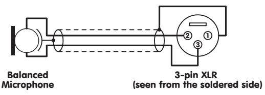
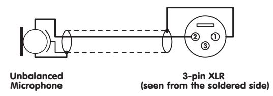
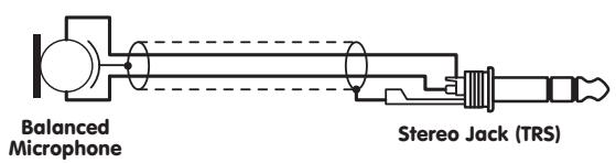

Note: Connecting unbalanced microphones to the amplifier when the phantom is switched on could lead to severe damage on the microphones and is therefore not recommended. It is absolutely mandatory to perform any plugging or unplugging of microphone cables with the phantom power turned off. Also, make sure that the phantom power is turned off when using microphones that are not meant to be operated with phantom power. The voltage is present on pin2 and pin3 of the XLR-connector could lead to severe damages on the microphones. When in doubt, please consult the owner's manual of the questionable microphone or contact your dealer before you perform any connections.
24. AM Loop Antenna (CA1T Only)
This antenna for receives AM frequency band waves.
25. FM Antenna (CA1T Only)
This antenna for receives FM frequency band waves.
26. INPUT 2, INPUT 3 and INPUT 4 Inputs Sensitivity and XLR Phantom Power 24V Switch
By turning these switches to the LINE position INPUT 2, INPUT 3 and INPUT4 can be connected to an audio source with high level signal output. By turning these switches to the MIC position the INPUT 2, INPUT 3 and INPUT4 can be connected to a dynamic microphone with low impedance. By selecting the switch to the 24V position, connects the 24V phantom supply on the XLR (pin2 and pin3) of INPUT 2, INPUT 3 and INPUT4. This is necessary to operate condenser type microphones which require this type of external supply.
It is recommended to use this switch with the master volume set to minimum.
27. Input Sensitivity Switch (AUX1, AUX2)
By setting these switches onto the "1" position the AUX1 and AUX2 inputs are suitable for connecting a CD-player. By setting these switches onto the "2" position the AUX1, AUX2 input is suitable for connecting an AM/FM radio signal output. By setting these switches onto the "3" position, the AUX1, AUX2 input are suitable for connecting to a desktop cassette player signal output. By setting these switches to the "4" position, the AUX1, AUX2 input are suitable for connected high-level signal outputs.
28. Telephone Paging Input Level Control
This control allows you to set the volume of the sound source that is connected to the TEL. Paging (29) terminal. Turning control clockwise increases the volume of the corresponding source. We recommend to leave the control at their minimal setting of "0" if not used.
29. Input TEL. Paging
The terminal strip input lets you connect to a telephone signal (600 ohms). The input features a VOICE PRIORITY function, which overrides all other input signals once a telephone signal is sensed. If you want to have this function disabled permanently, please contact a Yorkville Sound Service Center.
30. Priority Terminal
When short-circuiting these terminals (i.e. by means of using an electrical switch), the audio signals coming from AUX1, AUX2/TAPE, CASSETTE and TUNER are attenuated while the signals coming from INPUT1, INPUT2 and INPUT4 have priority.

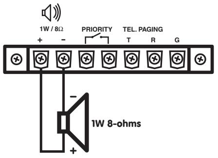
31. Output Terminal for Auxiliary Loudspeaker
This terminal is meant to connect a small external loudspeaker that is driven by an internal auxiliary power amplifier, providing a nominal output 1 watt. Only the mixed audio signal coming from AUX1, AUX2/TAPE, CASSETTE and TUNER are included in the outputted signal. In addition, the output signal is controlled only by the volume controls of the AUX1, AUX2/TAPE, TUNER and music signal level control (4). This function is toggled by the the MONITOR OUTPUT (5).
32. DC switch
This switch lets you turn the battery supply on or off
INSTALLATION NOTES
At all times, the amplifier has to be operated under appropriate conditions. This includes that the operation location provided sufficient ventilation and the device is not exposed to direct sunlight or direct radiation or reflection from any heat source. Installing the loudspeaker systems choose a location that gets not affected by extreme and/or constant vibration or other mechanical oscillation. Also make sure that the speakers are installed at locations that are free from dust and/or moisture.
CAUTION
We strongly recommend that you leave the connection of the appliance to the qualified and experienced service technical who is specialized in connecting electrical and electronically equipment. Do not take the risk of electro-shock or shock hazard. To reduce the risk of electro-shock all connections have to be accomplished before it is permissible to connect the amplifier to the main supply. Before connecting the appliance to the mains supply, once again make certain that all connections are carried out correctly and that no short-circuits exist. The overall sound reinforcement installation has to be in accordance to the laws regulations, standards and guidelines that are relevant and applicable in the country where the equipment is going to be operated.
AC POWER SUPPLY
CAUTION
Before using the amplifier for the first time make sure that the appliance IS set in accordance to your mains supply. Otherwise, please consult your Yorkville dealer who will configure your equipment for the correct voltage. Connect the amplifier only to grounded mains outlets. Connecting the amplifier to the mains supply (115Vac respectively 230Vac) has to be accomplished by inserting the supplied mains cord into the corresponding socket (15) and afterward plugging it into a mains outlet.
DC POWER SUPPLY
CAUTION
A 24V DC power source (i.e. a battery) has to be connected to the terminals (18) that are covered by the protective lid. To reduce the risk of dropping voltage to a minimum and to eliminate the danger of damaging the battery cables by thermal overload, these cables have to be at least 2.5mm2 in diameter, each. Switching the amplifier on or off is performed through the power switch (33).
CONNECTING THE OUTPUT TERMINALS
CAUTION
To avoid the risk of electrical shock, never touch the bare conductors leading to the output terminals of the amplifier when it is in operation. Under figures, show the possible connections of the OUTPUT speaker terminals accessible by removing the protective cover. Bear in mind the following rules:
Constant Impedance Lines
- The total impedance of the speakers connected must correspond to that selected on amplifier's output terminals.
- The sum of the power capacities of the speakers must be no lower than the amplifier's power capacity.
- The length of the connecting cables must be as possible; in any case, the longer the distance to be covered and the greater must be the cross-section of the cables.
Constant voltage lines
Each speaker must be equipped with a line transformer with an input voltage equal to that of the line (25, 70, 100V).
- The sum of the power capacities of the speakers must not exceed the output power capacity of the amplifier (i.e. total wattage of speakers installed in zones 1 through 4).
Technical data
Amplifier section
| Type | 60W-Mono-tabletop 120W-Mono-tabletop |
| Output power capacity | Nominal: 60W- maximum: 90W Nominal: 120W- maximum: 180W |
| Nominal power capacity with supply at 24Vdc | 45W 90W |
| Frequency response | 50-15,000Hz (±3dB) |
| Total harmonic distortion | ≤ 1% (1 kHz nominal power capacity) |
| Signal / noise ratio | INPUT 1-4, AUX 1 ,2: >45dB MAIN IN: >55dB |
| Inputs / sensitivity-impedance | INPUT 1 / 6.3mm jack / -54dB (2mV) -300Ω / unbalanced INPUT 2-4 / XLR and 6.3mm combination socket / balanced Micro: -60dB (1mV) - 600Ω Line: -22dB (75mV) -47KΩ AUX1-2 / stereo RCA jack / unbalanced 1: 0dB (1V) -240Ω (for CD player) 2: -6dB (500mV) -120KΩ (for tuner radio) 3: -10dB (300mV) -75KΩ (tor cassette player) 4: -20dB (100mV) -24KΩ (for auxiliary appliance) MAIN IN / mono RCA jack 10dB (1V) -1OKΩ / unbalanced |
| Outputs for speakers / ohms | 4 ohms |
| Outputs for speakers / Volts | 25V-70V-100V (10Ω, 83Ω, 170Ω) 25V-70V-100V (5Ω, 42Ω, 83Ω) |
| Additional outputs / voltage-impedance | PRE OUT / mono RCA jack / 1V-600Ω / unbalanced Loudspeaker / on terminal board / 1 watt-8Ω Monitor output / 6.3mm jack / 1.5V-6OOΩ / balanced |
| Tone controls | Bass ±10dB-100Hz Treble ±10dB-10kHz |
| Controls | 7 volume controls for INPUT 1-4, AUX1-2 and tel. paging 1 master volume control 1 treble control 1 bass control 5 zone paging select switch |
| Power supply / Consumption | 115/230 Vac (±5%-)-60/50Hz / 200VA 115/230 Vac (±5%-)-60/50Hz / 400VA |
| Direct current draw (24V) | 5A 10A |
| Dimensions (LxHxW) | 480mm x 320mm x 150 mm |
| Weight | CA1: 9kg CA1T: 12kg |
DTS radio tuner section
| Band | AM / FM |
| Tuning range | AM: 530kHz-1600kHz in 10kHz steps FM: 87.5MHz-108MHz in 100kHz steps |
| Controls | Radio ON / OFF with volume control Band selector button Frequency UP / DOWN button Memory button 5 memory buttons |
| Indicator | LCD |
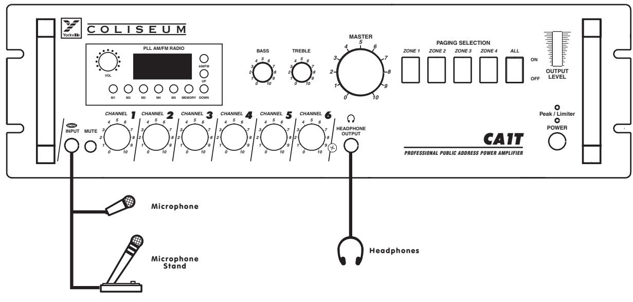
Example of possible connections
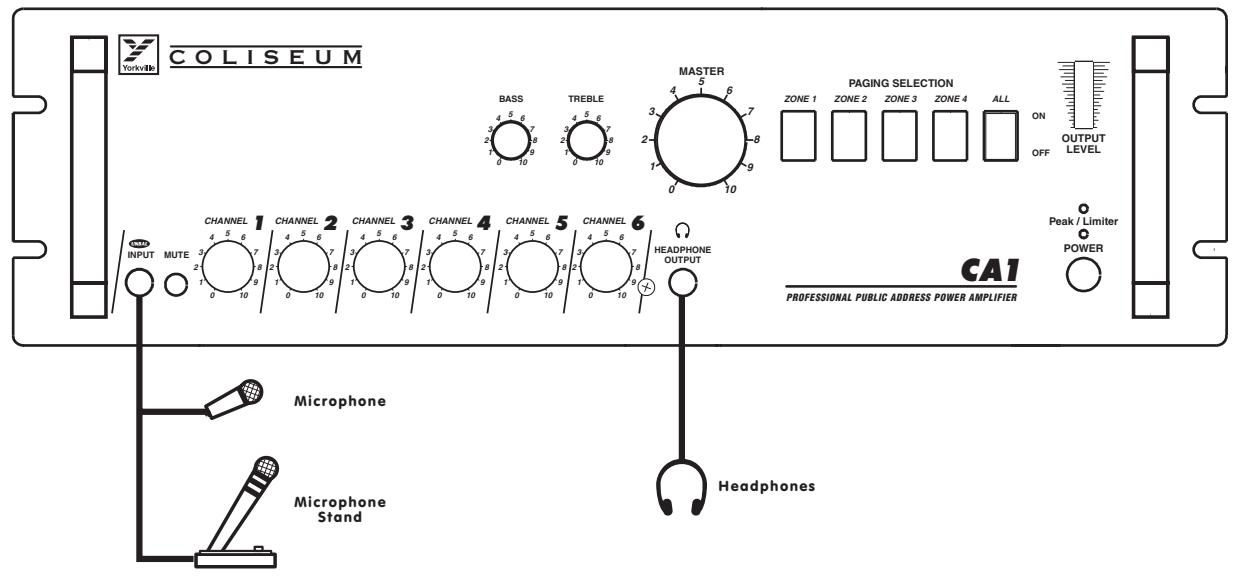
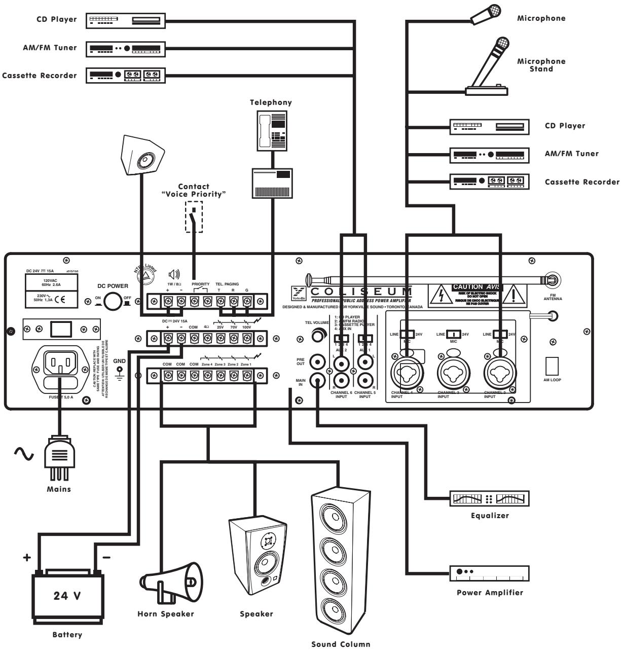
Description

Unbalanced Microphone
1/4-inch Mono Phone Plug
2. Sélecteur MUTE
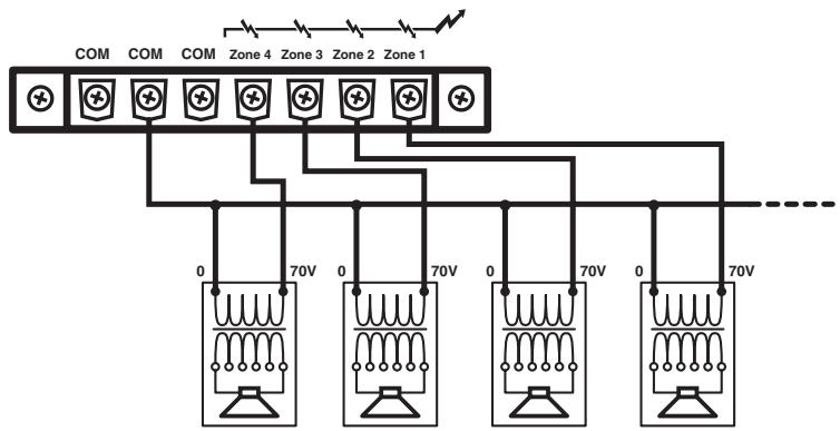
Connecting the speakers to 70V output
4-ohms
Connecting the speakers to 4-ohm output
Total Impedance 4-ohms
Connecting the speakers to 25V output
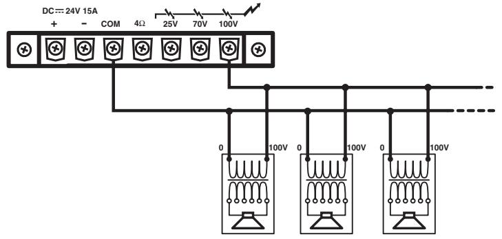
Connecting the speakers to 70V output
Connecting the speakers to 100V output
SOURCE D'ALIMENTATION CA
ATTENTION
Voice: (716) 297-2920
Fax: (716) 297-3689

Quality and Innovation Since 1963
Printed in China
- OWNER'S MANUAL PROFESSIONAL PUBLIC ADDRESS AMPLIFIER
- CA1·CA1T
- IMPORTANT NOTES
- CAUTION
- SAFETY PRECAUTIONS
- PRECAUTIONS
- NOTES IMPORTANT
- CONTROLS AND FUNCTIONS
- CHANNEL 1 INPUT
- MUTE SWITCH
- INPUT LEVEL CONTROLS
- MUSIC SIGNAL MONITOR OUTPUT LEVEL CONTROL
- MONITOR OUTPUT
- POWER SWITCH
- INDICATOR
- LED VU-METER
- ZONE SELECTION SWITCHES
- MASTER VOLUME CONTROL
- COMMON TREBLE CONTROL
- COMMON BASS CONTROL
- OPTIONAL DTS AM/FM TUNER (ONLY CAIT)
- REAR PANEL
- MAIN CORD CONNECTOR
- AC FUSE
- GND SCREW
- TERMINALS FOR THE DC BATTERY SUPPLY
- ZONE OUTPUT TERMINAL STRIP
- OUTPUT TERMINAL STRIP
- PRE OUT TERMINAL STRIP
- MAIN IN TERMINAL STRIP
- AUX 1 AND AUX 2 INPUTS
- INPUT 2, INPUT 3 AND INPUT 4 INPUTS
- AM LOOP ANTENNA (CA1T ONLY)
- FM ANTENNA (CA1T ONLY)
- INPUT 2, INPUT 3 AND INPUT 4 INPUTS SENSITIVITY AND XLR PHANTOM POWER 24V SWITCH
- INPUT SENSITIVITY SWITCH (AUX1, AUX2)
- TELEPHONE PAGING INPUT LEVEL CONTROL
- INPUT TEL. PAGING
- PRIORITY TERMINAL
- OUTPUT TERMINAL FOR AUXILIARY LOUDSPEAKER
- DC SWITCH
- INSTALLATION NOTES
- AC POWER SUPPLY
- DC POWER SUPPLY
- CONNECTING THE OUTPUT TERMINALS
- CONSTANT IMPEDANCE LINES
- CONSTANT VOLTAGE LINES
- DESCRIPTION
- SÉLECTEUR MUTE
- SOURCE D'ALIMENTATION CA
- ATTENTION
Brand : YORKVILLE
Model : CA1T
Category : Audio Amplifier