
A4.4 - Audio Amplifier YORKVILLE - Free user manual and instructions
Find the device manual for free A4.4 YORKVILLE in PDF.


| Product Type | Power Audio Amplifier |
| Brand | YORKVILLE |
| Model | A4.4 |
| Dimensions (W x D x H) | 45.2 x 48.2 x 8.9 cm |
| Weight | 11.4 kg (25 lb) |
| Power Supply | Switching power supply with power factor correction, 90-120 V~ |
| Output Power (Continuous, 2 channels) | 750 W x 2 at 8 Ω, 1200 W x 2 at 4 Ω |
| Output Power (Bridged, Continuous) | 2400 W at 8 Ω |
| Peak Power (2 channels) | 1200 W x 2 at 8 Ω, 2175 W x 2 at 4 Ω |
| Peak Power (Bridged) | 4350 W at 8 Ω |
| Frequency Response | 20 Hz - 20 kHz (± 1 dB) |
| Total Harmonic Distortion (THD) | < 0.1% at 1 kHz, 4 Ω |
| Inputs | 2 x XLR (balanced), 2 x 6.35 mm TRS jack (balanced/unbalanced) |
| Outputs | 2 x Speakon 4-pole, 5-way binding posts |
| Operating Modes | Stereo, Mono (dual mono), Bridge |
| Subsonic Filter | High-pass at 40 Hz, 12 dB/octave |
| Limiter | Switchable peak limiter (front/rear) |
| Protections | Short-circuit, DC, thermal, clipping |
| Cooling | Variable speed fan, front-to-back airflow |
| Fan Filter | User-cleanable (every 4 to 6 weeks) |
| Warranty | 2 years (10 years for cabinet) |
| Manufacturer | Yorkville Sound (Canada/USA) |
Frequently Asked Questions - A4.4 YORKVILLE
User questions about A4.4 YORKVILLE
0 question about this device. Answer the ones you know or ask your own.
Ask a new question about this device
Download the instructions for your Audio Amplifier in PDF format for free! Find your manual A4.4 - YORKVILLE and take your electronic device back in hand. On this page are published all the documents necessary for the use of your device. A4.4 by YORKVILLE.
USER MANUAL A4.4 YORKVILLE
OWNER'S MANUAL MANUEL DE'UTILISATEUR
A4.4
POWER FACTOR CORRECTED
IMPORTANT SAFETY INSTRUCTIONS
CAUTION AVIS
RISK OF ELECTRIC SHOCK
DO NOT OPEN
BISQUE DE CHOC ELECTRIQUE
NE PAS OUVRIB

INSTRUCTIONS PERTAINING TO A RISK OF FIRE, ELECTRIC SHOCK, OR INJURY TO PERSONS
CAUTION:
TO REDUCE THE RISK OF ELECTRIC SHOCK, DO
NOT REMOVE COVER (OR BACK).
NO USER SERVICEABLE PARTS INSIDE.
REFER SERVICING TO QUALIFIED
SERVICE PERSONNEL.
Read Instructions
The Owner's Manuals should be read and understood before operation of your unit. Please, save these instructions for future reference.
Packaging
Keep the box and packaging materials, in case the unit needs to be returned for service.
Warning
When using electric products, basic precautions should always be followed, including the following:
Power Sources
Your unit should be connected to a power source only of the voltage specified in the owners manual or as marked on the unit. This unit has a polarized plug. Do not use with an extension cord or receptacle unless the plug can be fully inserted. Precautions should be taken so that the grounding scheme on the unit is not defeated.
Hazards
Do not place this product on an unstable cart, stand, tripod, bracket or table. The product may fall, causing serious personal injury and serious damage to the product. Use only with cart, stand, tripod, bracket, or table recommended by the manufacturer or sold with the product. Follow the manufacturer's instructions when installing the product and use mounting accessories recommended by the manufacturer.
The apparatus should not be exposed to dripping or splashing water; no objects filled with liquids should be placed on the apparatus.
Terminals marked with the "lightning bolt" are hazardous live; the external wiring connected to these terminals require installation by an instructed person or the use of ready made leads or cords.
No naked flame sources, such as lighted candles, should be placed on the apparatus.
Power Cord
The AC supply cord should be routed so that it is unlikely that it will be damaged. If the AC supply cord is damaged DO NOT OPERATE THE UNIT.
Service
The unit should be serviced only by qualified service personnel.
INSTRUCTIONS RELATIVES AU RISQUE DE FEU, CHOC ÉLECTRIQUE, OU BLESSURES AUX PERSONNES
AVIS:
AFIN DE REDUIRE LES RISQUE DE CHOC ELECTRIQUE,
N'ENLEVEZ PAS LE COUVERT (OU LE PANNEAU ARRIERE)
NE CONTIENT AUCUNE PIECE
REPARABLE PAR L'UTILISATEUR.
CONSULTEZ UN TECHNICIEN QUALIFIE
POUR L'ENTRETIENT
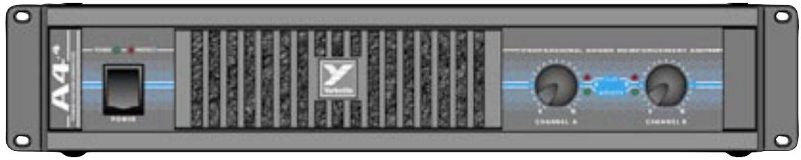
Your new Yorkville A4.4 power amplifier is designed and built to provide years of trouble free performance. The A4.4 combines the field-proven reliability of our Audiopro amplifiers with customer requested features such as switchable limiters, a Mono/Stereo/Bridge switch, and SPEAKON™ output connectors (as well as binding posts).
The A4.4 weighs an amazing 26 pounds, fits into two rack spaces, and reproduces music with over 4000 Watts of headroom. It will drive reactive phase shifted loads with no difficulty - even though it is fully protected from accidental short circuits. Our design goal was to create an amplifier which would do exactly what an amplifier should do: reproduce music with great power, complete reliability, and uncompromising signal fidelity. We think you will agree that the Yorkville A4.4 does exactly that.
What Makes the A4.4 So Different?
Power supplies convert energy from AC wall sockets into voltage that the power amplifiers use to amplify music. The A4.4 incorporates the latest technology in power supplies; power factor corrected switch mode power supply technology (SMPS). It reduces the weight of the A4.4 by 40% , compared to conventional amplifiers that use 60 Hz power transformers. Conventional amplifiers produce less than rated power when the AC wall voltage sags below 120 volts AC. By using SMPS technology, the A4.4 produce's its rated power even when the AC wall voltage drops to 90 volts! The type of switching power supply the A4.4 uses is called a "Power Factor Corrected." "Power Factor Corrected" means that the A4.4's power supply draws its power more efficiently from the wall socket than a conventional amplifier. This reduces the nuisance tripping of wall mounted circuit breakers when two amplifiers are connected to one wall socket.
1. Balanced Inputs
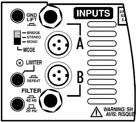
Either XLR or two-circuit TRS (Tip, Ring, Sleeve) Stereo 1/4-inch Phone cords may be used. Each channel's XLR input is internally paralleled with its phone input (The tip of the Channel A Phone input is connected to pin 2 of its XLR input, the Ring is connected to pin 3, and the sleeve is connected to pin 1). Pin 2 is in-phase, pin 3 is 180 degrees out-of-phase, and Pin 1 is ground. We recommend using balanced lines for the best hum-free performance, particularly when multiple amplifiers are used in a chain.
2. Unbalanced Inputs
Ordinary single circuit Standard 1/4-inch Phone plugs may be used to connect unbalanced signals.
IMPORTANT NOTE: Such plugs effectively connect the Ring terminal to Sleeve ground, so they work correctly. However, if you use a Stereo 1/4-inch Phone plug on an unbalanced line, you MUST short the Ring terminal to the Sleeve terminal, otherwise the sensitivity will be 6 dB lower than is specified! (The same applies to the XLR input: To connect an unbalanced source via the XLR input, you must connect the signal to Pin 2 and ground BOTH Pin 1 and Pin 3).

3. Remote Referencing
You can approach balanced performance with unbalanced sources by using the remote reference feature of the A4.4. Connect a balanced cable to the A4.4 just as you would if you were running a balanced line. At the other end, connect Pin 3 and Pin 1 together, (or connect ring to sleeve if you are using a Phone plug cable), and plug this modified end into your unbalanced piece of equipment. This connection enables the A4.4's input to look down the cable directly at the output jack of the unbalanced equipment. Any hum voltage generated across the cable's impedance will be attenuated by the Common Mode Rejection of the A4.4.



4. Driving Multiple A4.4's
In large installations it is often desirable to operate many amplifiers in tandem. Since each channel's XLR input is internally paralleled with its phone input, you may use the remaining input jack as an output to the next amplifier. Obviously you will need both XLR to XLR and Phone to Phone patch cords if you are going to tandem more than two amplifiers.
NOTE: These patch cords MUST be balanced whether the input signal is balanced or unbalanced!
5. Ground Switch
Switching the ground switch on the rear panel will disconnect chassis ground from circuit ground. Earth ground is still connected to the chassis. We do not recommend lifting the ground strap unless you are experiencing problems with ground loop hum in multiple amplifier setups where lifting the ground straps of all but one amplifier cures the hum problem.
CAUTION: Sometimes hum problems are an indication of improper AC wiring.. Don't just doctor the symptom by lifting grounds. Fix the cause by making sure that the proper electrical wiring safety regulations have been adhered to.
6. Modes
The A4.4 can be configured for dual-Mono, Stereo, or Bridged-Mono operation via the rear panel Mode switch. The following is a description of each mode:
Mono Mode
- Channel A & B inputs are paralleled
Each gain control adjusts the signal level for its respective channel - Output signals are of equal phase.
- Two loads are driven.
- Loads are connected between the BLACK and RED post on each channel.
Stereo Mode
- Two independent amplifiers, Amp A and Amp B.
- Two loads are driven.
- Loads are connected between the BLACK and RED posts on each channel.
Bridge Mode
- Channel A & B inputs are paralleled. GAIN-B has no effect.
- Output signals are equal in amplitude but opposite in phase.
- One load is driven.
- The load is connected between the two RED binding posts. The BLACK posts are not used.
7. Subsonic Filter Switch
The A4.4 features a specially designed Subsonic Filter which blocks potentially destructive energy in the band below 40Hz . This filter provides a 12 dB/octave skirt below 40Hz . It is implemented with a two pole network designed to minimize phase shift down to 40Hz . We recommend using this filter in conjunction with some subwoofoers and with all high power full range cabinets. With this filter disabled, the A4.4 is flat down to 20Hz , and rolls off at 12dB/Octave below that.
8. Limiter Switch
With the internal limiters activated, the A4.4's gain is continuously adjusted to fit the signal within the available dynamic range. Occasional clipping is permitted. The limiters will not only help to protect your system's horns and tweeters, but will automatically make the best use of the available dynamic headroom. With the limiters activated, all you need to do is turn up the signal level until you start to see some clipping. The limiters will make sure that you are getting the maximum clean power output at all times. Setting the switch to the IN position completely disables both limiters.
9. Protect LED
In the event of a shorted load or a load which is of too low an impedance for the amplifier to handle the Protect LED will flash alternately On and Off at about 3-second intervals. The sound may come on and off at 1/2 -second intervals. In this case, the fault is in the speakers, or the speaker cables, and should be located and remedied. No reset of the A4.4 is required to restore proper operation. The Protect LED will stay on if the amplifier has overheated. Check the speaker load impedance and any restrictions to air flow at the air intake or exhaust vents of the amplifier.
10. Short Circuit Protection
The A4.4 is fully protected against all possible passive load conditions. It can operate into a dead short continuously without damage however, we don't recommend that you short your A4.4 "just for fun." Shorts do create a lot of stress on the output devices. The output stage uses a unique triple slope VI-Limiting scheme which is sophisticated enough to remain inert during transient currents in excess of 100 amperes and phase angles of more than 45 degrees, yet is capable of protecting the output stage from damage due to accidental short circuits and improper loads.
11. DC Protection
In the unlikely event of the A4.4's output's going DC, a thyristor circuit will short the output terminals and divert all potentially harmful currents away from your speakers.

12. Thermal Protection
In the unlikely event that the A4.4 overheats, the signal will be sporadically cut off and the PROTECT LED will stay on. The A4.4 is designed and tested to operate under "worst case" conditions without shutting down, so if you experience a thermal shut down you should check for blocked air flow.
13. Cooling
The fan draws air in from the front and expels hot air through the rear vents. This is compatible with most installations. Since hot air rises, the heated air forcibly expelled from the back tends to rise away from the equipment rack. This draws cool air from the floor upwards into the front of the rack. In some cases where the rear of the rack is obstructed, it may be necessary to install rack fans to aid cooling. If there are no obstructions, no secondary cooling is required.

14. Fan Filter Maintenance
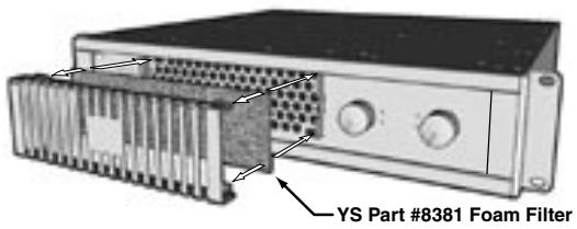
The A4.4 is factory equipped with a fan filter mounted on the air-intake grill located on the amplifier's front panel. Regular cleaning of this filter will increase the amplifier's long term reliability. The filter should be removed and washed at the first sign of visible clogging. This will typically occur every four to six weeks depending on use and environment. Replacement filters are inexpensive and can be ordered through Yorkville dealers. The foam filter should be removed if a regular inspection schedule is not going to be followed. The amplifier can operate without the filter in place, but the amplifier should be cleaned internally by a qualified service technician when dust is visible on the heatsink fins.
Note: In an unusually dusty location, without regular filter inspections, removing the foam filter can extend the operating time before thermal shutdown could occur. At that time, the internal heatsinks should be cleaned thoroughly.
15. Clip LEDs
The CLIP LEDs on the front panel will visibly indicate any signal excursion beyond the dynamic headroom of the amplifier.
16. Reliability
The A4.4 is designed and manufactured by Yorkville Sound. Each unit undergoes a thorough, temperature cycled burn-in period, and each circuit is tested by both manual and sophisticated computer controlled equipment which is capable of identifying any deviation from the design center parameters. The design of the A4.4 is conservative with respect to the power handling capabilities of the output devices. The topology guarantees that thermal stress not secondary breakdown will set the limits of operation, while the computer optimized heat dissipation system insures that excessive thermal stress will not occur. Yorkville's reputation as a manufacturer of reliable equipment will be further enhanced by the A4.4.
The A4.4 is not only suitable for use in both heavy duty touring sound reinforcement systems but also when high headroom and low distortion are needed to fully reproduce the dynamic range and clarity of today's CD recordings. It is built to survive grueling road conditions and constant 4 ohm operation. Its reliability in a fixed installation running 4 or 8-Ohm studio monitors is without parallel.
17. Output Connections
WARNING: When driven to full power in Bridge Mode, there is more than 100Vrms appearing between the binding posts. This represents a significant shock hazard and due care should be taken when making any speaker connections. Ensure that no strands of bare conductor are exposed after inserting the speaker wire into the hole in the side of the binding post terminals.
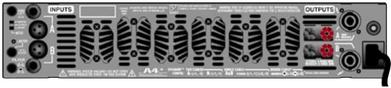
The A4.4 has 5-way binding posts and Neutrik four contact Speakon™ connectors for output speaker connections. Connection to the binding posts can either be made with a banana plug inserted into the end of the post, a spade connector or bare wires.
There are two Speakon™ connectors. The Speakons™ are connected to the amplifier's outputs whether the amplifier is in stereo, mono, or bridge modes. Each Speakon™ output connector (output A and output B) is wired in parallel with its respective binding posts for two channel two cable connections (figure 1).
Speakon™ output A also doubles as the A & B/Bridge connector. This Speakon™ contains both channels on one connector. This is convenient when connecting one speaker to the amplifier in bridge mode where the speaker is connected across the positives of each amplifier output. Configure the mode switch for bridge and connect the speaker to pins +1 and +2 of the bridge/bi-amp Speakon (figure 3).
To connect a bi-amp speaker, configure the amplifier for stereo and connect to the bridge/bi-amp connector but use all four terminals in the Speakon™ connector which will connect A and B outputs separately to the speaker (figure 2). Connection configurations are labeled on the back panel.


CAUTION: The A4.4 can deliver over 2400 Watts of power into a bridged load. Yorkville's own high power speaker systems have circuit-breaker protection built in. Although these speakers will protect themselves, they are unlikely to be damaged by a bridged A4.4. However, many other speaker manufacturers make "high power cabinets" with no protection features at all.
Yorkville Sound is not responsible for any damage which may result as a consequence of exceeding such a speaker's power handling capability. Yorkville's Two Year Unconditional Warranty does not cover any consequential damages to non-Yorkville equipment. Please consider these facts carefully before you choose to run your A4.4 in Bridge Mode!

18. Power Output
All values are in WATTS. Measurements were made at the 0.1% distortion point. Some CONTINUOUS AVERAGE POWER measurements required line currents greater than 15 Amps. The BURST measurements use a 10 mS burst at 1KHz with a 1/8 second pause between bursts. The 1KHz burst represents the maximum possible sine wave output power.
Both Channels Driven
| Load | 1KHz | 1KHz |
| (Ohms) | Cont. Avg. | Burst |
| 4-Ohm Mode | 4-Ohm Mode | |
| 8 | 750 | 1200 |
| 4 | 1200 | 2175 |
| 2 | n/a | n/a |
Bridge Mode
| Load | 1KHz | 1KHz |
| (Ohms) | Cont. Avg. | Burst |
| 4-Ohm Mode | 4-Ohm Mode | |
| 8 | 2400 | 4350 |
| 4 | n/a | n/a |
| 2 | n/a | n/a |
Specifications
Coninuous Average Power @ 8 ohms BCD (Watts) 750(x2)
Coninuous Average Power @ 4 ohms BCD (Watts) 1200(x2)
Coninuous Average Power @ 2 ohms BCD (Watts) NA
Continuous Average Power Bridged BCD (Watts) 2400 @ 8 ohms
Burst Average Power @ 8 ohms BCD (Watts) 1200(x2)
Burst Average Power @ 4 ohms BCD (Watts) 2175(x2)
Burst Average Power @ 2 ohms BCD (Watts) NA
Burst Average Power Bridged BCD (Watts) 4350 @ 8 ohms
Frequency Response (Hz, +/- 1dB) 20-20,000
Hum and Noise (un / Aweighted -dB) -103
THD -1kHz- 4 ohms less than 0.01%
THD - 20Hz-20kHz, 4 ohms less than 0.1%
Slew Rate (V/uS) 25
Slew Rate Bridged (V/uS) 50
Damping Factor (30 Hz - 400 Hz @ 8 ohms) greater than 600
Crosstalk (1kHz / 20Hz-20kHz) -75/-60 dB
Input Impedance - Bal/Unbal (ohms) 20,000/10,000
Input Sensitivity (Vrms) For Full Power Out 1.4 V
Max Voltage Gain (dB) 41
CMRR @ 60Hz (min/typ) 48/56 dB
Stereo / Mono / Bridge (S/M/B) S/M/B
Protection DC, Load, Thermal
Limiter User Defeatable Peak Limiter
High Pass Filter Yes
Cooling Variable speed DC Fan
Cooling Path Front to Back
Fan Filter User Serviceable
Inputs - XLR 2
Inputs - 1/4 -inch Jacks 2
Outputs - Speakon 4-pin 2
Outputs - Binding Post
Power Consumption (typ/max) 1800/3000
Rack Spaces 2
Transformer Type High Frequency Switch Mode
Exterior Finish Baked, Black Painted
H/D fm ears, inches) 17.8 × 19 × 3.5
Dimensions (DWH /D fm ears, cm) 45.2 x 48.2 x 8.9
Weight (Ibs/kg) 25/11.4
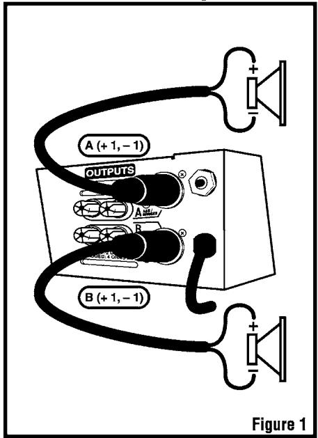
Two Channel Configuration
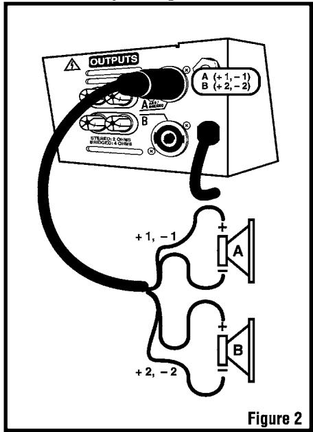
Bi Amp Configuration
Bridged Configuration
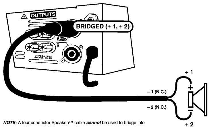
NOTE: A four conductor Speakon™ cable cannot be used to bridge into Speakon™ Standard cabinets. This will short the output of Channel B (+2) to Channel A (-1) inside the speaker cabinet.

Yorkville BRIDGE Mode SPEAKON™ Cable Hook-Up
Figure 3


Introduction
Puisance Moyenne Continue @ 2 ohms DCF (Watts) Non Applicable
Puisance Moyenne Continue En Pont (Watts) 2400 @ 8 ohms
Dimensions (PLH/P fm ears, pouces)
Dimensions (PLH /P fm ears, cm)
Poids (livres/kg) 2
48/56 dB
S/M/B
CC, Charge, Thermique
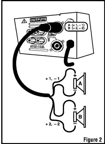
Configuration Bi-Amp
ap-detents-1v1.pdf July 17/2001
Unlimited Warranty
Yorkville's two and ten-year unlimited warranty on this product is transferable and does not require registration with Yorkville Sound or your dealer. If this product should fail for any reason within two years of the original purchase date (ten years for the wooden enclosure), simply return it to your Yorkville dealer with original proof of purchase and it will be repaired free of charge. This includes all Yorkville products, except for the YSM Series studio monitors, Coliseum Mini Series and TX Series Loudspeakers.
Freight charges, consequential damages, weather damage, damage as a result of improper installation, damages due to exposure to extreme humidity, accident or natural disaster are excluded under the terms of this warranty. Warranty does not cover consumables such as vacuum tubes or par bulbs. See your Yorkville dealer for more details. Warranty valid only in Canada and the United States.
Garantie Illimitée
Voice: (716) 297-2920
Fax: (716) 297-381
Niagara Falls, New York
14305 USA
Voice: (716) 297-2920
Fax: (716) 297-3689

- OWNER'S MANUAL MANUEL DE'UTILISATEUR
- IMPORTANT SAFETY INSTRUCTIONS
- CAUTION AVIS
- INSTRUCTIONS PERTAINING TO A RISK OF FIRE, ELECTRIC SHOCK, OR INJURY TO PERSONS
- CAUTION
- READ INSTRUCTIONS
- PACKAGING
- WARNING
- POWER SOURCES
- HAZARDS
- POWER CORD
- SERVICE
- INSTRUCTIONS RELATIVES AU RISQUE DE FEU, CHOC ÉLECTRIQUE, OU BLESSURES AUX PERSONNES
- AVIS
- WHAT MAKES THE A4.4 SO DIFFERENT
- BALANCED INPUTS
- UNBALANCED INPUTS
- REMOTE REFERENCING
- DRIVING MULTIPLE A4.4'S
- GROUND SWITCH
- MODES
- MONO MODE
- STEREO MODE
- BRIDGE MODE
- SUBSONIC FILTER SWITCH
- LIMITER SWITCH
- PROTECT LED
- SHORT CIRCUIT PROTECTION
- DC PROTECTION
- THERMAL PROTECTION
- COOLING
- FAN FILTER MAINTENANCE
- CLIP LEDS
- RELIABILITY
- OUTPUT CONNECTIONS
- POWER OUTPUT
- SPECIFICATIONS
- INTRODUCTION
- UNLIMITED WARRANTY
- GARANTIE ILLIMITÉE
Brand : YORKVILLE
Model : A4.4
Category : Audio Amplifier