
MSO5104 - Digital Oscilloscope TEKTRONIX - Free user manual and instructions
Find the device manual for free MSO5104 TEKTRONIX in PDF.
User questions about MSO5104 TEKTRONIX
0 question about this device. Answer the ones you know or ask your own.
Ask a new question about this device
Download the instructions for your Digital Oscilloscope in PDF format for free! Find your manual MSO5104 - TEKTRONIX and take your electronic device back in hand. On this page are published all the documents necessary for the use of your device. MSO5104 by TEKTRONIX.
USER MANUAL MSO5104 TEKTRONIX
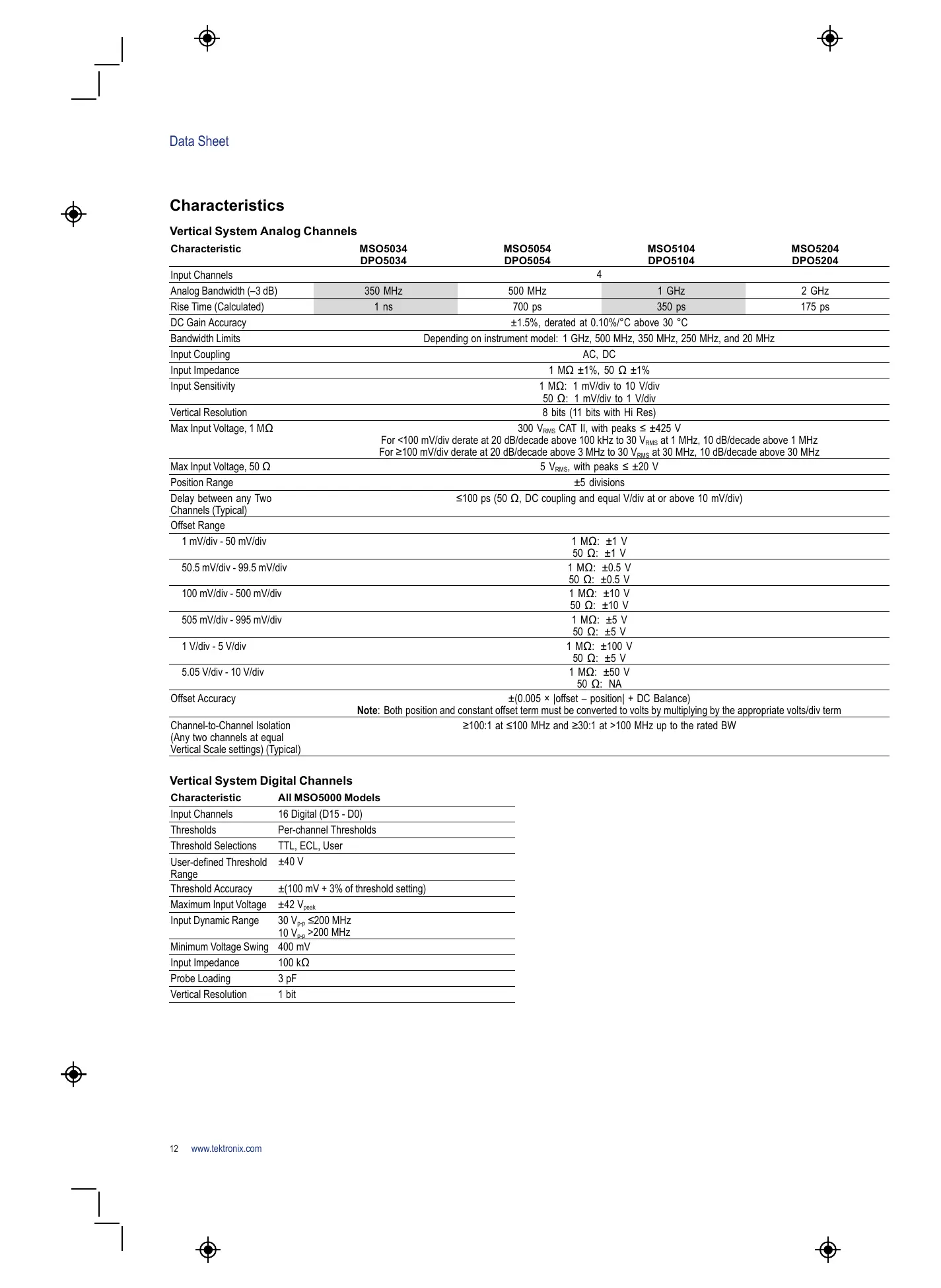
Vertical System Analog Channels
| Characteristic | MSO5034 DPO5034 | MSO5054 DPO5054 | MSO5104 DPO5104 | MSO5204 DPO5204 |
| Input Channels | 4 | |||
| Analog Bandwidth (-3 dB) | 350 MHz | 500 MHz | 1 GHz | 2 GHz |
| Rise Time (Calculated) | 1 ns | 700 ps | 350 ps | 175 ps |
| DC Gain Accuracy | ±1.5%, derated at 0.10%/°C above 30 °C | |||
| Bandwidth Limits | Depending on instrument model: 1 GHz, 500 MHz, 350 MHz, 250 MHz, and 20 MHz | |||
| Input Coupling | AC, DC | |||
| Input Impedance | 1 MΩ ±1%, 50 Ω ±1% | |||
| Input Sensitivity | 1 MΩ: 1 mV/div to 10 V/div50 Ω: 1 mV/div to 1 V/div | |||
| Vertical Resolution | 8 bits (11 bits with Hi Res) | |||
| Max Input Voltage, 1 MΩ | 300 VRMS CAT II, with peaks ≤ ±425 VFor <100 mV/div derate at 20 dB/decade above 100 kHz to 30 VRMS at 1 MHz, 10 dB/decade above 1 MHzFor ≥100 mV/div derate at 20 dB/decade above 3 MHz to 30 VRMS at 30 MHz, 10 dB/decade above 30 MHz | |||
| Max Input Voltage, 50 Ω | 5 VRMS, with peaks ≤ ±20 V | |||
| Position Range | ±5 divisions | |||
| Delay between any Two Channels (Typical) | ≤100 ps (50 Ω, DC coupling and equal V/div at or above 10 mV/div) | |||
| Offset Range | ||||
| 1 mV/div - 50 mV/div | 1 MΩ: ±1 V50 Ω: ±1 V | |||
| 50.5 mV/div - 99.5 mV/div | 1 MΩ: ±0.5 V50 Ω: ±0.5 V | |||
| 100 mV/div - 500 mV/div | 1 MΩ: ±10 V50 Ω: ±10 V | |||
| 505 mV/div - 995 mV/div | 1 MΩ: ±5 V50 Ω: ±5 V | |||
| 1 V/div - 5 V/div | 1 MΩ: ±100 V50 Ω: ±5 V | |||
| 5.05 V/div - 10 V/div | 1 MΩ: ±50 V50 Ω: NA | |||
| Offset Accuracy | ±(0.005 × |offset - position| + DC Balance)Note: Both position and constant offset term must be converted to volts by multiplying by the appropriate volts/div term | |||
| Channel-to-Channel Isolation (Any two channels at equal Vertical Scale settings) (Typical) | ≥100:1 at ≤100 MHz and ≥30:1 at >100 MHz up to the rated BW | |||
Vertical System Digital Channels
| Characteristic | All MSO5000 Models |
| Input Channels | 16 Digital (D15 - D0) |
| Thresholds | Per-channel Thresholds |
| Threshold Selections | TTL, ECL, User |
| User-defined Threshold Range | ±40 V |
| Threshold Accuracy | ±(100 mV + 3% of threshold setting) |
| Maximum Input Voltage | ±42 Vpeak |
| Input Dynamic Range | 30 Vp-d ≤200 MHz 10 Vp-d >200 MHz |
| Minimum Voltage Swing | 400 mV |
| Input Impedance | 100 kΩ |
| Probe Loading | 3 pF |
| Vertical Resolution | 1 bit |
Horizontal System Analog Channels
| Characteristic | MSO5034 DPO5034 | MSO5054 DPO5054 | MSO5104 DPO5104 | MSO5204 DPO5204 |
| Maximum Sample Rate (All channels) | 5 GS/s | 5 GS/s | 5 GS/s | 5 GS/s |
| Maximum Sample Rate (1 or 2 channels) | — | — | 10 GS/s | 10 GS/s |
| Maximum Equivalent Time Sampling Rate | 400 GS/s | |||
| Maximum Record Length with Standard Configuration | 12.5M | 12.5M (4 ch) 25M (1 or 2 ch) | ||
| Maximum Record Length with Option 2RL | 25M | 25M (4 ch) 50M (1 or 2 ch) | ||
| Maximum Record Length with Option 5RL | 50M | 50M (4 ch) 125M (1 or 2 ch) | ||
| Maximum Record Length with Option 10RL | 125M | 125M (4 ch) 250M (1 or 2 ch) | ||
| Maximum Duration at Highest Real-Time Sample Rate | 25 ms | |||
| Time Base Range | 250 ps/div to 1000 s/div | |||
| Time Resolution (in ET/IT mode) | 2.5 ps/div | |||
| Time Base Delay Time Range | -5 divisions to 5000 s | |||
| Channel-to-Channel Deskew Range | ±75 ns | |||
| Trigger Jitter (RMS) | ≤10 psRMS for Edge trigger type ≤100 psRMS for all Non-edge trigger types | |||
| Time Base Accuracy | ±5 ppm over any ≥1 ms interval | |||
Horizontal System Digital Channels
| Characteristic | All MSO5000 Models |
| Maximum Sample Rate (Main) | 500 MS/s (2 ns resolution) |
| Maximum Record Length (Main) | 12.5M Standard Up to 40M with Record Length options |
| Maximum Sample Rate (MagniVu) | 16.5 GS/s (60.6 ps resolution) |
| Maximum Record Length (MagniVu) | 10k points centered around the trigger |
| Minimum Detectable Pulse Width | 1 ns |
| Channel-to-Channel Skew (typical) | 200 ps |
| Maximum Input Toggle Rate | 500 MHz at minimum input swing; higher toggle rates can be achieved at higher amplitudes |
Trigger System
| Characteristic | Description |
| Main Trigger Modes | Auto, Normal, and Single |
| Trigger Coupling | DC, AC, HF Rej (attenuates >50 kHz), LF Rej (attenuates <50 kHz), Noise Reject (reduces sensitivity) |
| Trigger Holdoff Range | 250 ns to 8 s |
| Trigger Sensitivity | |
| Internal DC Coupled | For 1 MΩ: 1 mV/div to 4.98 mV/div: 0.75 div from DC to 50 MHz, increasing to 1.3 div at instrument bandwidth ≥5 mV/div: 0.40 div from DC to 50 MHz, increasing to 1 div at instrument bandwidth For 50 Ω: 0.40 div from DC to 50 MHz, increasing to 1 div at instrument bandwidth |
| External (Auxiliary Input) | 200 mV from DC to 50 MHz, increasing to 500 mV at 250 MHz |
| 1 MΩ | |
| Trigger Level Range | |
| Any Channel | ±8 divisions from center of screen |
| External (Auxiliary Input) | ±8 V |
| Line | Fixed at about 50% of line voltage |
Trigger Modes
Mode
| Mode | Description |
| Edge | Positive or negative slope on any channel or front-panel auxiliary input. Coupling includes DC, AC, HF reject, LF reject, and noise reject |
| Glitch | Trigger on or reject glitches of positive, negative, or either polarity. Programmable glitch width is 4 ns minimum to 8 s maximum |
| Runt | Trigger on a pulse that crosses one threshold but fails to cross a second threshold before crossing the first again |
| Width | Trigger on width of positive or negative pulse either within or outside of selectable limits (4 ns to 8 s) |
| Timeout | Trigger on an event which remains high, low, or either, for a specified time period (4 ns to 8 s) |
| Transition | Trigger on pulse edge rates that are faster or slower than specified. Slope may be positive, negative, or either |
| Setup/Hold | Trigger on violations of both setup time and hold time between clock and data present on any two input channels |
| Pattern | Trigger when any logical pattern of signals goes false or stays true for specified period of time (4 ns to 1 s). Pattern (AND, OR, NAND, NOR) specified for all analog and digital input channels defined as High, Low, or Don't Care |
| State | Any logical pattern of analog channels and digital channels (MSO models) clocked by edge on another channel. Trigger on rising or falling clock edge |
| Video | Trigger on all lines, specific line number, odd, even, or all fields on NTSC, PAL, SECAM, and HDTV 480p/60, 576p/50, 875i/60, 720p/30, 720p/50, 720p/60, 1080/24sF, 1080i/50, 1080p/25, 1080i/60, 1080p/24, 1080p/25, 1080p/50, 1080p/60, Bi-level, Tri-level |
| Trigger Sequences | Main, Delayed by Time, Delayed by Events. All sequences can include separate horizontal delay after the trigger event to position the acquisition window in time |
| A/B Sequence Event Trigger Types | Edge |
| Trigger Delay by Time | 4 ns to 8 s |
| Trigger Delay by Events | 1 to 4,000,000 events |
| I²C (Optional) | Trigger on Start, Repeated Start, Stop, Missing ACK, Address (7 or 10 bit), Data, or Address and Data on I²C buses up to 10 Mb/s |
| SPI (Optional) | Trigger on SS or data on SPI buses up to 10 Mb/s |
| RS-232/422/485/UART (Optional) | Trigger on Start Bit, End of Packet, Data, and Parity Error up to 10 Mb/s |
USB (Optional)
Description
| Low-speed: Trigger on Sync, Reset, Suspend, Resume, End of Packet, Token (Address) Packet, Data Packet, Handshake Packet, Special Packet, Error. Token Packet Trigger – Any token type, SOF, OUT, IN, SETUP; Address can be specified for Any, OUT, IN, and SETUP token types. Address can be further specified to trigger on ≤, <, =, >, ≥, != a particular value, or inside or outside of a range. Frame number can be specified for SOF token using Binary, Hex, Unsigned Decimal, and Don't Care digits. Data Packet Trigger – Any data type, DATA0, DATA1; Data can be further specified to trigger on ≤, <, =, >, ≥, != a particular data value, or inside or outside of a range. Handshake Packet Trigger – Any handshake type, ACK, NAK, STALL. Special Packet Trigger – Any special type, Reserved. Error Trigger – PID Check, CRC5 or CRC16, Bit Stuffing. |
| Full-speed: Trigger on Sync, Reset, Suspend, Resume, End of Packet, Token (Address) Packet, Data Packet, Handshake Packet, Special Packet, Error. Token Packet Trigger – Any token type, SOF, OUT, IN, SETUP; Address can be specified for Any, OUT, IN, and SETUP token types. Address can be further specified to trigger on ≤, <, =, >, ≥, != a particular value, or inside or outside of a range, Frame number can be specified for SOF token using Binary, Hex, Unsigned Decimal, and Don't Care digits. Data Packet Trigger – Any data type, DATA0, DATA1; Data can be further specified to trigger on ≤, <, =, >, ≥, != a particular data value, or inside or outside of a range. Handshake Packet Trigger – Any handshake type, ACK, NAK, STALL. Special Packet Trigger – Any special type, PRE, Reserved. Error Trigger – PID Check, CRC5 or CRC16, Bit Stuffing. |
| High-speed: Trigger on Sync, Reset, Suspend, Resume, End of Packet, Token (Address) Packet, Data Packet, Handshake Packet, Special Packet, Error. Token Packet Trigger – Any token type, SOF, OUT, IN, SETUP; Address can be specified for Any, OUT, IN, and SETUP token types. Address can be further specified to trigger on ≤, <, =, >, ≥, != a particular value, or inside or outside of a range; Frame number can be specified for SOF token using Binary, Hex, Unsigned Decimal, and Don't Care digits. Data Packet Trigger – Any data type, DATA0, DATA1; DATA2, DATAM; Data can be further specified to trigger on ≤, <, =, >, ≥, != a particular data value, or inside our outside of a range. Handshake Packet Trigger – Any handshake type, ACK, NAK, STALL, NYET. Special Packet Trigger – Any special type, ERR, SPLIT, PING, Reserved. SPLIT packet components that can be specified include: Hub Address Start/Complete – Don't Care, Start (SSPLIT), Complete (CSPLIT) Port Address Start and End bits – Don't Care, Control/Bulk/Interrupt (Full-speed Device, Low-speed Device), Isochronous (Data is Middle, Data is End, Data is Start, Data is All) Endpoint Type – Don't Care, Control, Isochronous, Bulk, Interrupt Error Trigger – PID Check, CRC5, CRC16, Any. |
Note: High-speed support only available on 1 GHz and 2 GHz models.
Trigger Characteristics
| Characteristic | Description |
| Enhanced Triggering | User-selectable; corrects the difference in timing between the trigger path and the acquired data (not available in FastAcq) |
Acquisition Modes
| Mode | Description |
| Sample | Acquire sampled values |
| Peak Detect | Captures narrow glitches as narrow as 100 ps (2 GHz and 1 GHz models) or 200 ps (500 MHz and 350 MHz models) at all real-time sampling rates |
| Averaging | From 2 to 10,000 waveforms included in average |
| Envelope | Min-Max envelope reflecting Peak Detect data over multiple acquisitions |
| Hi Res | Real-time boxcar averaging reduces random noise and increases resolution |
| Roll | Scrolls sequential waveform points across the display in a right-to-left rolling motion at sweep speeds slower than 50 ms/div. Up to 20 MS/s with a maximum record length of 10M |
| FastAcq Acquisition Mode | FastAcq optimizes the instrument for analysis of dynamic signals and capture of infrequent events |
| Maximum FastAcq Waveform Capture Rate | >250,000 wfms/s on all 4 channels simultaneously |
| Waveform Database | Accumulate waveform database providing three-dimensional array of amplitude, time, and counts |
| \(FastFrame^{TM}\ Acquisition\) | Acquisition memory divided into segments; maximum trigger rate >310,000 waveforms per second. Time of arrival recorded with each event. Frame finder tool helps to visually identify transients |
Search and Mark Events
| Characteristic | Description |
| Automated Search and Mark | Automatically mark events and document waveforms. Search positive/negative slopes or both, glitches, runts, pulse widths, transition rate, setup and hold, timeout, windows, or find any logic or state pattern on any number of channels. Search DDR Read or Write bursts with Opt. DDRA. Event table summarizes all found events. All events are time stamped in reference to trigger position. Stop acquisitions when an event is found |
Waveform Measurements
| Measurement | Description |
| Cursors | Waveform and Screen |
| Automatic Measurements | 53, of which 8 can be displayed on-screen at any one time. Measurements include: Period, Frequency, Delay, Rise Time, Fall Time, Positive Duty Cycle, Negative Duty Cycle, Positive Width, Negative Width, Burst Width, Phase, Positive Overshoot, Negative Overshoot, Peak-to-Peak, Amplitude, High, Low, Maximum, Minimum, Mean, Cycle Mean, RMS, Cycle RMS, Area, Cycle Area |
| Eye-pattern Measurements | Extinction Ratio (absolute, %, dB), Eye Height, Eye Width, Eye Top, Eye Base, Crossing %, Jitter (p-p, RMS, 6sigma), Noise (p-p, RMS), Signal/Noise Ratio, Cycle Distortion, Q-Factor |
| Measurement Statistics | Mean, Minimum, Maximum, Standard Deviation |
| Reference Levels | User-definable reference levels for automatic measurements can be specified in either percent or units |
| Gating | Isolate the specific occurrence within an acquisition to take measurements on, using either screen or waveform cursors |
| Waveform Histogram | A waveform histogram provides an array of data values representing the total number of hits inside of a user-defined region of the display. A waveform histogram is both a visual graph of the hit distribution as well as a numeric array of values that can be measured. Sources – Channel 1, Channel 2, Channel 3, Channel 4, Ref 1, Ref 2, Ref 3, Ref 4, Math 1, Math 2, Math 3, Math 4 Types – Vertical, Horizontal |
| Waveform Histogram Measurements | Waveform Count, Hits in Box, Peak Hits, Median, Maximum, Minimum, Peak-to-Peak, Mean (μ), Standard Deviation (sigma), μ+1sigma, μ+2sigma, μ+3sigma |
Waveform Processing/Math
| Characteristic | Description |
| Arithmetic | Add, Subtract, Multiply, Divide waveforms and scalars |
| Algebraic Expressions | Define extensive algebraic expressions including waveforms, scalars, user-adjustable variables, and results of parametric measurements. Perform math on math using complex equations.e.g. (Integral (CH1 - Mean(CH1)) × 1.414 × VAR1) |
| Math Functions | Average, Invert, Integrate, Differentiate, Square Root, Exponential, Log10, Log e, Abs, Ceiling, Floor, Min, Max, Sin, Cos, Tan, Asin, ACos, ATan, Sinh, Cosh, Tanh |
| Relational | Boolean result of comparison >, <, ≥, ≤, ==, != |
| Frequency Domain Functions (FFT) | Spectral Magnitude and Phase, Real and Imaginary Spectra |
| FFT Vertical Units | Magnitude: Linear, dB, dBm |
| Phase: Degrees, radians, group delay | |
| IRE and mV units | |
| FFT Window Functions | Rectangular, Hamming, Hanning, Kaiser-Bessel, Blackman-Harris, Gaussian, Flattop2, Tek Exponential |
| Waveform Definition | As an arbitrary math expression |
| Filtering Functions | User-definable filters. Users specify a filter containing the coefficients of the filter. Filter files provided |
| Mask Function | A function that generates a waveform database bitmap from a sample waveform. Sample count can be defined |
Software
| Software | Description |
| NI LabVIEW | A fully interactive measurement software environment optimized for the MSO/DPO5000 Series, enables you to instantly acquire, generate, analyze, compare, import, and save measurement data and signals using an intuitive drag-and-drop user interface that does not require any programming. |
| SignalExpress Tektronix Edition | Standard MSO/DPO5000 Series support for acquiring, controlling, viewing, and exporting your live signal data is permanently available through the software. The full version (SIGEXPTE) adds additional signal processing, advanced analysis, mixed signal, sweeping, limit testing, and user-defined step capabilities and is available for a 30-day trial period standard with each instrument. |
| IVI Driver | Provides a standard instrument programming interface for common applications such as LabVIEW, LabWindows/CVI, Microsoft .NET and MATLAB. IVI-COM standard |
| LXI Class C Web Interface | Connect to the MSO/DPO5000 Series through a standard web browser by simply entering the oscilloscope's IP address in the address bar of the browser. The web interface enables viewing of instrument status and configuration, as well as status and modification of network settings. All web interaction conforms to LXI Class C specification |
Display Characteristics
| Characteristic | Description |
| Display Type | Liquid-crystal active-matrix color display with touch screen |
| Display Size | Diagonal: 10.4 in. (264 mm) |
| Display Resolution | 1024 horizontal × 768 vertical pixels (XGA) |
| Waveform Styles | Vectors, Dots, Variable Persistence, Infinite Persistence |
| Color Palettes | Normal, Green, Gray, Temperature, Spectral, and User Defined |
| Display Format | YT, XY |
Computer System and Peripherals
| Characteristic | Description |
| Operating System | Windows 7 Ultimate 64-bit |
| CPU | Intel Core 2 Duo, ≥2 GHz processor |
| PC System Memory | ≥4 GB |
| Hard Disk Drive | Removable hard disk drive, ≥160 GB capacity (2.5 in. SATA) |
| Mouse | Optical wheel mouse, USB interface |
| Keyboard | Order 119-7083-xx for small keyboard; USB interface and hub |
Input/Output Ports
| Port | Description |
| USB 2.0 High-speed Host Ports | Supports USB mass storage devices, printers, keyboard, and mouse. Two ports on front and four ports on rear of instrument. Can be disabled individually |
| USB 1.1 Full-speed Device Port | Rear-panel connector allows for communication/control of oscilloscope through USBTMC or GPIB (with a TEK-USB-488 adapter) |
| LAN Port | RJ-45 connector, supports 10/100/1000BASE-T |
| Video Out Port | DB-15 female connector, connect to show the oscilloscope display on an external monitor or projector. Support for extended desktop and clone mode |
| Audio Ports | Miniature phono jacks |
| Keyboard Port | PS/2 compatible |
| Mouse Port | PS/2 compatible |
| Auxiliary Input | Front-panel BNC connector. Input impedance 1 MΩ. Max input 300 VRMS with peaks ≤ ±425 V |
| Auxiliary Out (Software switchable) | Trigger Out: A TTL compatible pulse when the oscilloscope triggers Time Base Reference Out: A TTL compatible output of internal 10 MHz reference oscillator |
| External Reference In | Time base system can phase lock to an external 10 MHz reference (10 MHz ±1%) |
| Probe Compensator Output | Front-panel pins Amplitude: 2.5 V Frequency: 1 kHz |
Lan eXtensions for Instrumentation (LXI)
| Characteristic | Description |
| Class | LXI Class C |
| Version | V1.3 |
Power Source
| Characteristic | Description |
| Power Source Voltage | 100 to 240 V ±10% |
| Power Source | 45 Hz to 66 Hz (85 to 264 V) |
| Frequency | 360 Hz to 440 Hz (100 to 132 V) |
| Power Consumption | 275 W maximum |
Physical Characteristics
| Dimension | mm | in. |
| Height | 233 | 9.16 |
| Width | 439 | 17.29 |
| Depth | 206 | 8.12 |
| Weight | kg | lb. |
| Net | 6.7 | 14.9 |
| Shipping | 12.5 | 27.5 |
| Rackmount Configuration | 5U | |
| Cooling Clearance | 2 in. (51 mm) required on left side and rear of instrument | |
Environmental
| Characteristic | Description |
| Temperature | |
| Operating | 5 °C to +50 °C |
| Nonoperating | -20 °C to +60 °C |
| Humidity | |
| Operating | 8% to 90% relative humidity with a maximum wet-bulb temperature of 29 °C at or below +50 °C (upper limit de-rates to 20.6% relative humidity at +50 °C). Noncondensing |
| Nonoperating | 5% to 98% relative humidity with a maximum wet-bulb temperature of 40 °C at or below +60 °C (upper limit de-rates to 29.8% relative humidity at +60 °C). Noncondensing |
| Altitude | |
| Operating | 9,843 ft. (3,000 m) |
| Nonoperating | 30,000 ft. (9,144 m) |
| Regulatory | |
| Electromagnetic compatibility | 2004/108/EC |
| Certifications | UL61010-1, Second Edition; CSA61010-1 Second Edition, EN61010-1:2001; IEC 61010-1:2001 |
Ordering Information
MSO/DPO5000 Family
| Product | Description |
| DPO5000 Models | |
| DPO5034 | 350 MHz, 5 GS/s, 12.5M record length, 4-channel digital phosphor oscilloscope |
| DPO5054 | 500 MHz, 5 GS/s, 12.5M record length, 4-channel digital phosphor oscilloscope |
| DPO5104 | 1 GHz, 10/5 GS/s (2/4 ch), 12.5M record length, 4-channel digital phosphor oscilloscope |
| DPO5204 | 2 GHz, 10/5 GS/s (2/4 ch), 12.5M record length, 4-channel digital phosphor oscilloscope |
| MSO5000 Models | |
| MSO5034 | 350 MHz, 5 GS/s, 12.5M record length, 4+16 channel mixed signal oscilloscope |
| MSO5054 | 500 MHz, 5 GS/s, 12.5M record length, 4+16 channel mixed signal oscilloscope |
| MSO5104 | 1 GHz, 10/5 GS/s (2/4 ch), 12.5M record length, 4+16 channel mixed signal oscilloscope |
| MSO5204 | 2 GHz, 10/5 GS/s (2/4 ch), 12.5M record length, 4+16 channel mixed signal oscilloscope |
All Models Include: One passive voltage probe per analog channel (TPP0500: 500 MHz, 10X, 3.9 pF for 500 MHz and 350 MHz models; TPP1000: 1 GHz, 10X, 3.9 pF for 2 GHz and 1 GHz models), front cover (200-5130-xx), touch-screen stylus (119-6107-xx), user manual (071-2790-xx), NI LabVIEW SignalExpress Tektronix Edition software, accessory pouch, mouse, Calibration Certificate documenting measurement traceability to National Metrology Institute(s), Z 540-1 Compliance and ISO9001, power cord, one-year warranty.
MSO Models also Include: P6616 16-channel logic probe and a logic probe accessory kit (020-2662-xx).
Note: Please specify power plug and manual language version when ordering.
Options
Record Length Options
| Option | MSO5034 | MSO5104 |
| DPO5034 | DPO5104 | |
| MSO5054 | MSO5204 | |
| DPO5054 | DPO5204 | |
| Opt. 2RL | 25M/Ch | 50M max, 25M/Ch |
| Opt. 5RL | 50M/Ch | 125M max, 50M/Ch |
| Opt. 10RL | 125M/Ch | 250M max, 125M/Ch |
Software Options
| Option | Description |
| Opt. DDRA*1 | DDR Memory Bus Analysis |
| Opt. DJA | Jitter and Eye Analysis Tools – Advanced (DPOJET) |
| Opt. ET3*2 | Ethernet Compliance Testing |
| Opt. LT | Waveform Limit Testing |
| Opt. MTM | Mask Testing - ITU-T (64 Kb/s to 155 Mb/s) - ANSI T1.102 (1.544 Mb/s to 155 Mb/s) - Ethernet IEEE 802.3, ANSI X3.263 (125 Mb/s to 1.25 Gb/s) - Sonet/SDH (51.84 Mb/s to 622 Mb/s) - Fibre Channel (133 Mb/s to 2.125 Gb/s) - Fibre Channel Electrical (133 Mb/s to 1.06 Gb/s) - USB (12 Mb/s to 480 Mb/s) - IEEE 1394b (491.5 Mb/s to 1.966 Gb/s) - Rapid I/O Serial (up to 1.25 Gb/s) - Rapid I/O LP-LVDS (500 Mb/s to 1 Gb/s) - OIF Standards (1.244 Gb/s) - CPI, V4.0 (1.228 Gb/s) - Video (143.18 Mb/s to 360 Mb/s) |
| Opt. PWR | Power Measurement and Analysis |
| Opt. SR-COMP | Computer Serial Triggering and Analysis (RS-232/422/485/UART) Enables triggering on packet-level information on RS-232/422/485/UART buses as well as analytical tools such as digital views of the signal, bus views, and packet decoding. Signal Inputs – Any Ch1 - Ch4 (and any D0 - D15 on MSO models) Recommended Probing – RS-232/UART: Single ended; RS-422/485: Differential |
| Opt. SR-EMBD | Embedded Serial Triggering and Analysis (I2C, SPI) Enables triggering on packet-level information on I2C and SPI buses as well as analytical tools such as digital views of the signal, bus views, and packet decoding. Signal Inputs – I2C: Any Ch1 - Ch4 (and any D0 - D15 on MSO models); SPI: Any Ch1 - Ch4 (and any D0 - D15 on MSO models) Recommended Probing – I2C, SPI: Single ended |
| Opt. SR-USB | USB Serial Triggering and Analysis (LS, FS, HS) Enables triggering on packet-level content for low-speed, full-speed, and high-speed USB serial buses. Also enables analytical tools such as digital views of the signal, bus views, and packet decoding for low-speed, full-speed, and high-speed USB serial buses. Signal Inputs – Low-speed and Full-speed: Any Ch1 - Ch4 (and any D0 - D15 on MSO models) for single ended, Any Ch1 - Ch4 for differential; High-speed: Any Ch1 - Ch4 Recommended Probing – Low-speed and Full-speed: Single ended or differential; High-speed: Differential USB high-speed supported only on MSO5204, DPO5204, MSO5104, and DPO5104 models. |
| Opt. USB*3 | USB 2.0 Compliance Testing |
| Opt. VNM | CAN/LIN Protocol Analysis Software |
| Option | Description |
| Bundle Options | |
| Opt. PS1 | Power Solution Bundle: DPOPWR, P5205, TCP0030, TPA-BNC, 067-1686-xx (Deskew Fixture) |
Floating licenses offer an alternative method to manage your Tektronix asset. Floating licenses allow license-key enabled options to be easily moved among all your MSO/DPO5000, DPO7000, and DPO/DSA/MSO70000 Series of Tektronix oscillosopes. Floating licenses are available for many license-key enabled options. To order a floating version of an option license add "DPOFL-" prefix to the option name. (e.g. DPOFL-ET3) Check www.tek.com/products/oscillosopes/floatinglicenses for additional information about floating license options.
1 Requires Opt. DJA. Available on 1 GHz and 2 GHz models only.
2 Requires TF-GBE-BTP or TF-GBE-ATP Ethernet Test Fixture.
*3 Requires TDSUSBF (USB Test Fixture). 2 GHz bandwidth required for high-speed USB.
Power Plug Options
| Option | Description |
| Opt. A0 | North America |
| Opt. A1 | Universal European Union |
| Opt. A2 | UK |
| Opt. A3 | Australia |
| Opt. A5 | Switzerland |
| Opt. A6 | Japan |
| Opt. A10 | China |
| Opt. A11 | India |
| Opt. A12 | Brazil |
| Opt. A99 | No power cord |
User Manual Options
| Option | Description |
| Opt. L0 | English manual |
| Opt. L1 | French manual |
| Opt. L3 | German manual |
| Opt. L5 | Japanese manual |
| Opt. L7 | Simplified Chinese manual |
| Opt. L8 | Traditional Chinese manual |
| Opt. L9 | Korean manual |
| Opt. L10 | Russian manual |
Service Options*4
| Option | Description |
| Opt. CA1 | Provides a single calibration event, or coverage for the designated calibration interval, whichever comes first |
| Opt. C3 | Calibration Service 3 Years |
| Opt. C5 | Calibration Service 5 Years |
| Opt. D1 | Calibration Data Report |
| Opt. D3 | Calibration Data Report 3 Years (with Opt. C3) |
| Opt. D5 | Calibration Data Report 5 Years (with Opt. C5) |
| Opt. G3 | Complete Care 3 Years (includes loaner, scheduled calibration, and more) |
| Opt. G5 | Complete Care 5 Years (includes loaner, scheduled calibration, and more) |
| Opt. R3 | Repair Service 3 Years (including warranty) |
| Opt. R5 | Repair Service 5 Years (including warranty) |
*4 Probes and accessories are not included in the oscilloscope warranty. Refer to the data sheet for each probe for its unique warranty and calibration terms.
Recommended Accessories
Probes
Tektronix offers over 100 different probes to meet your application needs. For a comprehensive listing of available probes, please visit wwwTektronix.com/probes.
| Probe | Description |
| TPP0500 | 500 MHz, 10X TekVPI® passive voltage probe with 3.9 pF input capacitance |
| TPP1000 | 1 GHz, 10X TekVPI passive voltage probe with 3.9 pF input capacitance |
| TAP2500 | 2.5 GHz TekVPI active single-ended voltage probe |
| TAP1500 | 1.5 GHz TekVPI active single-ended voltage probe |
| TDP3500 | 3.5 GHz TekVPI differential voltage probe with ±25 V differential input voltage |
| TDP1500 | 1.5 GHz TekVPI differential voltage probe with ±25 V differential input voltage |
| TDP1000 | 1 GHz TekVPI differential voltage probe with ±42 V differential input voltage |
| TDP0500 | 500 MHz TekVPI differential voltage probe with ±42 V differential input voltage |
| TCP0150 | 20 MHz TekVPI 150 Ampere AC/DC current probe |
| TCP0030 | 120 MHz TekVPI 30 Ampere AC/DC current probe |
| P5200 | 1.3 kV, 25 MHz high-voltage differential probe |
| P5205*5 | 1.3 kV, 100 MHz high-voltage differential probe |
| P5210*5 | 5.6 kV, 50 MHz high-voltage differential probe |
| P5100 | 2.5 kV, 100X high-voltage passive probe |
*5 Requires TekVPI® to TekProbe BNC adapter (TPA-BNC).
Accessories
| Accessory | Description |
| 077-0076-xx | Service Manual |
| 077-0010-10 | Programmer Manual |
| 077-0063-05 | Performance Verification and Specifications Manual |
| SIGEXPTE | NI LabVIEW SignalExpress Tektronix Edition Software (Full Version) |
| TPA-BNC | TekVPI-to-TekProbe BNC Adapter |
| TEK-USB-488 | GPIB-to-USB Adapter |
| HCTEK54 | Hard Transit Case |
| RMD5000 | Rackmount Kit |
| 119-7083-xx | Mini Keyboard (USB interface) |
| 119-6297-xx | Full-size keyboard with 4-port USB hub |
| 119-7766-xx | External DVD R/W Drive |
| 065-0851-xx | Removable HD Spare with rotational media |
| K420 | Oscilloscope Cart |
Cables
| Cable | Description |
| 012-0991-xx | GPIB Cable (1 m) |
| 012-0991-xx | GPIB Cable (2 m) |
Test Fixtures
| Fixture | Description |
| TDSUSBF | Test fixture for use with Opt. USB |
| TF-GBE-BTP | Basic test package for 10/100/1000BASE-T Ethernet tests |
| TF-GBE-ATP | Advanced test package for 10/100/1000BASE-T Ethernet (includes 1000BASE-T jitter test channel cable) |
| TF-GBE-EE | Additional test fixture for Energy Efficient Ethernet measurements |
| Ethernet Test Fixture | Order through Crescent Heart Software (http://www.c-h-s.com) |
Adapters
| Adapter | Description |
| P6701B*4 | Optical/Electrical Converter (Multi Mode) |
| P6703B*4 | Optical/Electrical Converter (Single Mode) |
*4 Probes and accessories are not included in the oscilloscope warranty. Refer to the data sheet for each probe for its unique warranty and calibration terms.
Instrument Upgrades
Floating licenses offer an alternative method to manage your Tektronix asset. Floating licenses allow license-key enabled options to be easily moved among all your MSO/DPO5000, DPO7000, and DPO/DSA/MSO70000 Series of Tektronix oscillosopes. Floating licenses are available for many license-key enabled options. To order a floating version of an option license add "DPOFL-" prefix to the option name. (e.g. DPOFL-ET3) Check www tek.com/products/oscillosopes/floatinglicenses for additional information about floating license options.
To upgrade your MSO/DPO5000 Series oscilloscope, order DPO-UP and option listed below. For example, DPO-UP DDRA.
| Option | Description |
| To upgrade record length: | |
| RL02E | From Standard Configuration to Opt. 2RL Configuration |
| RL05E | From Standard Configuration to Opt. 5RL Configuration |
| RL010E | From Standard Configuration to Opt. 10RL Configuration |
| RL25E | From Opt. 2RL Configuration to Opt. 5RL Configuration |
| RL210E | From Opt. 2RL Configuration to Opt. 10RL Configuration |
| RL510E | From Opt. 5RL Configuration to Opt. 10RL Configuration |
| To upgrade MSO/DPO5000 Series with: | |
| DDRA*1 | Add Opt. DDRA |
| DJAE | Add Opt. DJA – Jitter and Eye Analysis Tools - Advanced (DPOJET) |
| ET3*2 | Add Opt. ET3 – Ethernet Compliance Testing |
| LT | Add Opt. LT – Waveform Limit Testing |
| MTM | Add Opt. MTM – Mask Testing |
| PWR | Add Opt. PWR – Power Measurement and Analysis |
| SR-COMP | Add Opt. SR-COMP – Computer Serial Triggering and Analysis (RS-232/422/485/JUART) |
| SR-EMBD | Add Opt. SR-EMBD – Embedded Serial Triggering and Analysis (I2C, SPI) |
| SR-USB | Add Opt. SR-USB – USB Serial Triggering and Analysis (LS, FS, HS) |
| USB*3 | Add Opt. USB – USB Compliance Testing |
| VNM | Add Opt. VNM – CAN/LIN Serial Protocol Decode |
| To upgrade DPO5000 Series with: | |
| MSOE | Add 16-digital channels to a DPO5000 |
1 Requires Opt. DJA. Available on 1 GHz and 2 GHz models only.
2 Requires TF-GBE-BTP or TF-GBE-ATP Ethernet Test Fixture.
*3 Requires TDSUSBF (USB Test Fixture). 2 GHz bandwidth required for high-speed USB.
For Further Information
Tektronix maintains a comprehensive, constantly expanding collection of application notes, technical briefs and other resources to help engineers working on the cutting edge of technology. Please visit www.tektronix.com

Copyright © 2010, Tektronix, Inc. All rights reserved. Tektronix products are covered by U.S. and foreign patents, issued and pending. Information in this publication supersedes that in all previously published material. Specification and price change privileges reserved. TEKTRONIX and TEK are registered trademarks of Tektronix, Inc. All other trade names referenced are the service marks, trademarks or registered trademarks of their respective companies.
20 Oct 2010
48F-26096-0